US8311129B2 - Temporal video filtering - Google Patents
Temporal video filtering Download PDFInfo
- Publication number
- US8311129B2 US8311129B2 US11/611,494 US61149406A US8311129B2 US 8311129 B2 US8311129 B2 US 8311129B2 US 61149406 A US61149406 A US 61149406A US 8311129 B2 US8311129 B2 US 8311129B2
- Authority
- US
- United States
- Prior art keywords
- pixel
- video frame
- range
- thresholds
- video
- Prior art date
- Legal status (The legal status is an assumption and is not a legal conclusion. Google has not performed a legal analysis and makes no representation as to the accuracy of the status listed.)
- Active, expires
Links
Images


Classifications
-
- H—ELECTRICITY
- H04—ELECTRIC COMMUNICATION TECHNIQUE
- H04N—PICTORIAL COMMUNICATION, e.g. TELEVISION
- H04N7/00—Television systems
- H04N7/14—Systems for two-way working
- H04N7/141—Systems for two-way working between two video terminals, e.g. videophone
Definitions
- the present invention relates generally to video and, more specifically, to video filtering.
- a video image may be displayed on a display using multiple Picture Elements (pixels).
- the number of possible shades for a pixel on the display may depend, in part, on the number of bits used for each pixel. For example, if 8 bits are used for each pixel, the pixel may have one of 256 (2 ⁇ 8) possible colors or shades of gray.
- Each frame in a series of video frames may include several pixels.
- Image elements with relatively no movement such as the background, may have pixel values that stay fairly constant between each frame (e.g., the pixels representing the image element may not change very much between frames in a series of frames).
- the pixel values in the respective portions of the video frames in the series may be identical.
- noise e.g., from different electronic sources, camera jitter, etc.
- pixels for non-moving objects may have different values between frames (noise may also affect the values of moving object pixels as well).
- the previous frame's pixel values may be kept without needing to refresh their values.
- the transmission bandwidth for video frames may then be focused on transmitting moving pixels (or vectors representing changing values for a series of pixels).
- moving pixels or vectors representing changing values for a series of pixels.
- temporal filtering may be used to reduce noise over time in a series of video frames.
- a temporal filter may use previous filtered frames (or other frames such as previous unfiltered frames) to reduce the noise in a new frame.
- a temporal filter may be used to filter noise in still parts of an image more strongly than in moving parts of the image.
- a temporal filter requiring less processing power may include a method for detecting motion between a set of pixels and applying the temporal filter based on the detected motion. For example, if substantial motion is not detected, the temporal filter for the block of pixels may be stronger (i.e., reduce more noise) than the temporal filter applied to a block of pixels for which substantial motion has been detected.
- FIG. 1 illustrates a video conferencing system, according to an embodiment
- FIG. 2 illustrates a participant location or conferencing unit, according to an embodiment
- FIGS. 3 a - e illustrate various distributions for temporal filtering
- FIGS. 4 a - d illustrate comparisons of various pixel sets, according to an embodiment
- FIG. 5 illustrates a method for temporal filtering, according to an embodiment
- FIG. 6 illustrates a method for temporal filtering using various thresholds, according to an embodiment
- FIG. 7 illustrates a specific embodiment of the method for temporal filtering using various thresholds, according to an embodiment.
- FIG. 1 illustrates an embodiment of a videoconferencing system 100 .
- Video conferencing system 100 comprises a plurality of participant locations or endpoints.
- FIG. 1 illustrates an exemplary embodiment of a videoconferencing system 100 which may include a network 101 , endpoints 103 A- 103 H (e.g., audio and/or video conferencing systems), gateways 130 A- 130 B, a service provider 107 (e.g., a multipoint control unit (MCU)), a public switched telephone network (PSTN) 120 , conference units 105 A- 105 D, and plain old telephone system (POTS) telephones 106 A- 106 B.
- MCU multipoint control unit
- PSTN public switched telephone network
- POTS plain old telephone system
- Endpoints 103 C and 103 D- 103 H may be coupled to network 101 via gateways 130 A and 130 B, respectively, and gateways 130 A and 130 B may each include firewall, network address translation (NAT), packet filter, and/or proxy mechanisms, among others.
- Conference units 105 A- 105 B and POTS telephones 106 A- 106 B may be coupled to network 101 via PSTN 120 .
- conference units 105 A- 105 B may each be coupled to PSTN 120 via an Integrated Services Digital Network (ISDN) connection, and each may include and/or implement H.320 capabilities.
- ISDN Integrated Services Digital Network
- video and audio conferencing may be implemented over various types of networked devices.
- endpoints 103 A- 103 H, gateways 130 A- 130 B, conference units 105 C- 105 D, and service provider 107 may each include various wireless or wired communication devices that implement various types of communication, such as wired Ethernet, wireless Ethernet (e.g., IEEE 802.11), IEEE 802.16, paging logic, RF (radio frequency) communication logic, a modem, a digital subscriber line (DSL) device, a cable (television) modem, an ISDN device, an ATM (asynchronous transfer mode) device, a satellite transceiver device, a parallel or serial port bus interface, and/or other type of communication device or method.
- wireless Ethernet e.g., IEEE 802.11
- IEEE 802.16 paging logic
- RF (radio frequency) communication logic paging logic
- modem e.g., a modem
- DSL digital subscriber line
- cable cable
- ISDN ISDN
- ATM asynchronous transfer mode
- satellite transceiver device e.g.,
- the methods and/or systems described may be used to implement connectivity between or among two or more participant locations or endpoints, each having voice and/or video devices (e.g., endpoints 103 A- 103 H, conference units 105 A- 105 D, POTS telephones 106 A- 106 B, etc.) that communicate through various networks (e.g., network 101 , PSTN 120 , the Internet, etc.).
- voice and/or video devices e.g., endpoints 103 A- 103 H, conference units 105 A- 105 D, POTS telephones 106 A- 106 B, etc.
- networks e.g., network 101 , PSTN 120 , the Internet, etc.
- Endpoints 103 A- 103 C may include voice conferencing capabilities and include or be coupled to various audio devices (e.g., microphones, audio input devices, speakers, audio output devices, telephones, speaker telephones, etc.).
- Endpoints 103 D- 103 H may include voice and video communications capabilities (e.g., video conferencing capabilities) and include or be coupled to various audio devices (e.g., microphones, audio input devices, speakers, audio output devices, telephones, speaker telephones, etc.) and include or be coupled to various video devices (e.g., monitors, projectors, displays, televisions, video output devices, video input devices, cameras, etc.).
- endpoints 103 A- 103 H may comprise various ports for coupling to one or more devices (e.g., audio devices, video devices, etc.) and/or to one or more networks.
- Conference units 105 A- 105 D may include voice and/or video conferencing capabilities and include or be coupled to various audio devices (e.g., microphones, audio input devices, speakers, audio output devices, telephones, speaker telephones, etc.) and/or include or be coupled to various video devices (e.g., monitors, projectors, displays, televisions, video output devices, video input devices, cameras, etc.).
- endpoints 103 A- 103 H and/or conference units 105 A- 105 D may include and/or implement various network media communication capabilities.
- endpoints 103 A- 103 H and/or conference units 105 C- 105 D may each include and/or implement one or more real time protocols, e.g., session initiation protocol (SIP), H.261, H.263, H.264, H.323, among others.
- endpoints 103 A- 103 H may implement H.264 encoding for high definition video streams.
- a codec may implement a real time transmission protocol.
- a codec (which may be short for “compressor/decompressor”) may comprise any system and/or method for encoding and/or decoding (e.g., compressing and decompressing) data (e.g., audio and/or video data).
- communication applications may use codecs to convert an analog signal to a digital signal for transmitting over various digital networks (e.g., network 101 , PSTN 120 , the Internet, etc.) and to convert a received digital signal to an analog signal.
- codecs may be implemented in software, hardware, or a combination of both.
- Some codecs for computer video and/or audio may include Moving Picture Experts Group (MPEG), Indeo, and Cinepak, among others.
- MPEG Moving Picture Experts Group
- Indeo Indeo
- Cinepak among others.
- At least one of the participant locations may include a camera for acquiring high resolution or high definition (e.g., HDTV compatible) signals. At least one of the participant locations may include a high definition display (e.g., an HDTV display), for displaying received video signals in a high definition format.
- the network 101 may be 1.5 MB or less (e.g., T1 or less). In another embodiment, the network is 2 MB or less.
- the video conferencing system may support high definition capabilities.
- the term “high resolution” includes displays with resolution of 1280 ⁇ 720 pixels and higher.
- high-definition resolution may comprise 1280 ⁇ 720 progressive scan at 60 frames per second, or 1920 ⁇ 1080 interlaced or 1920 ⁇ 1080 progressive.
- a video conferencing system may support high definition “e.g. similar to HDTV” display capabilities using network infrastructures with bandwidths T1 capability or less.
- high-definition is intended to have the full breath of its ordinary meaning and includes “high resolution”.
- FIG. 2 illustrates an embodiment of a participant location, also referred to as an endpoint or conferencing unit (e.g., a video conferencing system).
- the video conference system may have a system codec 209 to manage both a speakerphone 205 / 207 and a video conferencing system 203 .
- a speakerphone 205 / 207 and a video conferencing system 203 may be coupled to the integrated video and audio conferencing system codec 209 and may receive audio and/or video signals from the system codec 209 .
- speakerphones 205 / 207 may be daisy chained together.
- the speakerphone 205 / 207 may be a high quality speakerphone.
- 16 microphones may be radially distributed around a center speaker. Other numbers of microphones and speakers may also be used. The microphones may be radially distributed to enhance detection of an in-room participant's voice from multiple angles relative to the speakerphone 205 / 207 .
- the participant location may include a high definition camera 204 for acquiring high definition images of the participant location.
- the participant location may also include a high definition display 201 (e.g., a HDTV display).
- High definition images acquired by the camera may be displayed locally on the display and may also be encoded and transmitted to other participant locations in the videoconference.
- data from camera may be provided to the video conferencing system through a digital link from the camera.
- the data may be processed external to the camera (e.g., with the logic of the system codec 209 ).
- the data may be processed inside the camera.
- the participant location may also include a sound system 261 .
- the sound system 261 may include multiple speakers including left speakers 271 , center speaker 273 , and right speakers 275 . Other numbers of speakers and other speaker configurations may also be used.
- the video conferencing system components may be coupled to a system codec 209 .
- the system codec 209 may receive audio and/or video data from a network.
- the system codec 209 may send the audio to the speakerphone 205 / 207 and/or sound system 261 and the video to the display 201 .
- the received video may be high definition video that is displayed on the high definition display.
- the system codec 209 may also receive video data from the camera 204 and audio data from the speakerphones 205 / 207 and transmit the video and/or audio data over the network to another conferencing system.
- the conferencing system may be controlled by a participant 211 through the user input components (e.g., buttons) on the speakerphone 205 / 207 and/or remote control 250 .
- Other system interfaces may also be used.
- temporal filtering may be used to reduce noise over time in a series of video frames.
- a temporal filter may use previous filtered frames (or other frames) to reduce the noise in a new frame.
- the temporal filter may filter noise in still parts of an image more strongly than in moving parts of the image.
- no filtering may result in a one-to-one correlation between the input frame (the new frame) (e.g., a frame of data received from the camera) and the resultant frame.
- the new frame e.g., a frame of data received from the camera
- a modified temporal filter may be applied to remove noise from the new frame resulting in a filtered frame.
- the temporal filter may compare the new frame and a previous filtered frame (or another previous filtered frame, an otherwise modified previous frame, or an unmodified previous new frame). For example, corresponding blocks of pixels may be compared between the new frame and the previous filtered frame.
- an average frame calculated from averaging multiple previous frames e.g., previous filtered frames, otherwise modified previous frames, or unmodified previous new frames
- weighted averages of multiple previous frames may be used. Weights applied may vary.
- the previous filtered frame may be weighted forty percent, and each of the three filtered frames prior to the previous filtered frame may be weighted twenty percent.
- the resulting weighted frame values may be added together to form a weighted filtered frame to be compared to the new frame data.
- Other weights and distributions of weights are also contemplated. For example, in some embodiments, only the previous two filtered frames may be used (each weighted at fifty percent).
- the new frame and the previous filtered frame may be compared pixel by pixel.
- groups of corresponding pixels may be compared between the frames. For example, groups of three pixels from each frame may be added together and compared to corresponding sums between frames. Other numbers of pixels may also be used.
- pixel refers to a numerical value of a pixel (and/or subpixel) (e.g., “pixel” may be used to refer to an integer value assigned to the red subpixel component of a pixel comprised of three subpixels).
- subpixels may be processed as pixels.
- groups of three pixels may be averaged (e.g., added together and divided by three) for the comparison with corresponding averaged pixels.
- Other methods of combining pixels for comparisons are also contemplated (e.g., weighted averages, etc.).
- the comparison may include calculating a difference between corresponding pixels (or an average, sum, etc. of the pixels) of the new frame and the previous filtered frame.
- a difference may be calculated between a subset (e.g., a three by three block of nine pixels) of corresponding pixels from the new frame and the previous filtered frame.
- Corresponding pixels may be in a similar location (e.g., with respect to the frame boundaries) on the new frame and the previous filtered frame.
- the comparison may include calculating a difference between corresponding pixels (or an average, sum, etc. of the pixels) of the new frame and another previous filtered frame, an otherwise modified previous frame, or an unmodified previous new frame.
- the comparison may be used to construct the new filtered frame.
- FIG. 3 b illustrates an embodiment of a difference distribution line 317 a to apply to pixels of a frame to produce a filtered frame.
- the x-axis may represent the difference in value between a pixel on the new frame and a respective pixel on the previous filtered frame (or average difference of groups of corresponding pixels, etc.).
- the difference distribution line 317 a may also be used for other comparisons (e.g., differences between averaged or weighted frames).
- the y-axis may represent the corresponding offset applied to (e.g., added to) a pixel or group of pixels of the previous filtered frame (or other frame) to produce the next frame (i.e., the next filtered frame).
- the corresponding offset (y-axis) of the difference distribution line 317 a (corresponding to the difference on the x-axis) may be applied to the new frame to produce the next filtered frame.
- the corresponding offset may be applied to an average or weighted average of several frames (e.g., previous filtered frames or previous unmodified frames) to produce the next filtered frame.
- a corresponding offset of 0 may be added to the corresponding pixel of the previous filtered frame (or other frame used in the comparison) to produce the new frame (e.g., new filtered frame) pixel (e.g., see region 303 of line 317 a ). Because the difference may be relatively small, the difference may be assumed to be primarily associated with noise.
- the 0 (or small offset value) may be added to the corresponding previous filtered frame pixel instead of using the corresponding new frame pixel to effectively eliminate the effect of noise on the corresponding new frame pixel.
- “adding” may include directly increasing or decreasing the value of the pixel by the offset value or in some other way affecting the value of the pixel to effectively increase or decrease the value of the pixel by the offset value.
- the pixel may be divided by a number (e.g., a number between 1 and 0) that results in a new value that is effectively the value of the pixel increased by the offset. Other ways of affecting the value of the pixel are also contemplated.
- 0 may be added to each pixel of a corresponding group of pixels (e.g., which were added or averaged for the comparison). In some embodiments, 0 may be added to a subset of the corresponding group of pixels (e.g., applied to the center pixel in a group of three by three corresponding pixels). As used herein, “subset” may refer to a single element in a set. In some embodiments, 0 may be added to a corresponding pixel (or group of pixels) on the previous unmodified frame (i.e., previous new frame) to produce the new filtered frame. Modifying pixels or groups of pixels on other types of frames to produce the filtered frame are also possible.
- an offset value may be averaged with, for example, the corresponding pixel of the previous filtered frame instead of (or in addition to) adding an offset value (e.g., 0) to the corresponding pixels.
- an offset value e.g., 0
- Other modifications are also contemplated (e.g., subtracted from, divided by, etc.).
- the threshold may be dependent, for example, on the type of sensor used to capture the image data. For example, ⁇ 5 to 5 may be used for MicronTM CMOS sensors (Complementary Metal-Oxide Semiconductor sensors) and a 10-bit pixel space. Other threshold values may also be used for MicronTM CMOS sensors (for example, region 303 may be expanded to extend between ⁇ 10 and +10). Other sensors may also be used. For example, AtlasensTM sensors may be used (and may have a wider threshold, for example, if the sensors produce more noise than MicronTM sensors). The threshold values may also be dependent on the type of space used for the pixels.
- the pixel space may extend from 0 to 255, and if the image uses 10 bits per pixel, the pixel space may extend from 0 to 1023 (which may result in larger corresponding thresholds than the 8 bit pixel space thresholds).
- the size of region 303 (or the thresholds defining region 303 ) or other regions of the difference distribution line 317 a may be a predetermined value(s) entered by a user of, for example, a video conferencing system. In some embodiments, the size of the region 303 may be dependent on noise detected between the frames.
- the difference between a pixel (or group of pixels) of the new frame and a corresponding pixel (or group of pixels) of the previous filtered frame (or other frame(s)) may be added to the respective pixel of the previous filtered frame (or other frame(s)). This may result in a value approximately equal to the pixel value of the new frame pixel.
- the difference may be primarily associated with movement. To capture the movement, the difference (or a substantial portion of the difference) may be allowed to carry over to the corresponding pixel of the new filtered frame.
- the new frame pixel may be used instead of adding the corresponding difference (e.g., when the difference exceeds a threshold). Other modifications are also contemplated (e.g., averaging, subtracted from, divided by, etc.).
- the threshold may be user defined.
- a non-linear region 305 a,b may be used between region 303 and regions 307 a,b .
- region 305 a may extend between 5 and 32 for a 10-bit pixel space.
- Other thresholds are also contemplated. These thresholds may also depend on the type of sensors used and the type of space used for the pixel values.
- region 305 a,b may be linear (e.g., see regions 305 a,b of difference distribution line 317 b in FIG. 3 c ).
- Other region sizes and shapes are also contemplated.
- other numbers of regions may also be used. For example, as seen in FIG.
- linear regions 304 a,b and non-linear regions 306 a,b may be used.
- the difference between the corresponding pixels (or groups of pixels) on the x-axis may be used to determine the associated corresponding difference on the y-axis (e.g., through difference distribution lines 317 a,b,c ) to apply (e.g., added to the previous filtered frame) to produce the new filtered frame.
- the non-linear region (e.g., regions 305 a,b ) (and/or other regions of the filter) may be provided by one or more look-up tables with corresponding values of differences (x) and offsets (y). For example, these tables may provide a digital orientation to emulate an Infinite Impulse Response (IIR) filter for this region.
- the look-up tables may represent different shapes that may be used to provide different types of filtering. For example, in some embodiments, a look-up table may be used to provide an offset that increasingly recognizes the difference as movement.
- the non-linear portion may instead minimize the difference applied (e.g., to provide a stronger noise filter). Other tables are also contemplated.
- the tables may be calculated through trial and error. In some embodiments, the tables may be derived using different formulas.
- region 303 may represent a noise region. If the difference between the new pixel value and the respective filtered pixel value is in region 303 , it may be attributed to noise and may be filtered out (e.g., by effectively adding 0 to the previous filtered pixel value). As the difference increases (and correspondingly the portion of the difference attributable to noise decreases), the new pixel value may be given more weight (e.g., see regions 307 a,b ). In some embodiments, at relatively large differences, the new pixel value may become the next filtered pixel value (e.g., by adding the respective difference to the previous filtered pixel to effectively use the new pixel or by using the new pixel.)
- all or a substantial portion of the difference distribution line may be based on a continuous function instead of including separate regions.
- A may equal 1 or another number (e.g., the larger A is, the flatter the difference distribution line 317 d may be near the origin).
- Other functions are also contemplated.
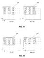
- a temporal filter requiring less processing power may include a method for detecting motion between a set of pixels and applying the temporal filter based on the detected motion. For example, if substantial motion is not detected (e.g., as between old block 451 in old filtered frame 401 and new block 453 in new frame 403 in FIG. 4 a ), the temporal filter for the block of pixels may be stronger (e.g., to reduce more noise) than the temporal filter applied to a block of pixels for which substantial motion has been detected (e.g., as between old block 451 in old filtered frame 401 and new block 457 in new frame 405 in FIG. 4 b ).
- the values of the previous filtered set of pixels 401 may be subtracted from the values of the corresponding pixels in the new frame set of pixels 403 (e.g., N) and the respective differences may be summed together into a resultant.
- a resultant for respective blocks of nine elements e.g., O
- weighted values may be compared or other pixel sets may be brought into the equation (e.g., the old unfiltered set of pixels, etc., may be used to create equations that provide different resultants).
- a first running average e.g., calculated average of the past several new data frames
- a second running average e.g., calculated average of the past several filtered frames
- differences between pixels of the first running average and the second running average may be summed to determine the resultant sum.
- the difference between the sets may be primarily the result of noise. In this case, there may be little or no motion and the resultant (divided by the number of pixels in a set) may approximately equal the noise:
- more motion may mean a larger resultant (e.g., because of larger differences between the corresponding pixels). If some or all of the pixels are moving, the resultant may be very large (because movement may result in a large correlated resultant).
- a weaker temporal filter e.g., with a smaller noise region 303
- no filtering may be applied.
- a stronger filter may be applied (e.g., with a larger region 303 ).
- the resultant may be compared to various thresholds to determine whether to use a strong or weak temporal filter (or to not use a temporal filter).
- the size of the resultant may be used to determine whether to apply the filter to one or more pixels of the set of pixels.
- the resultant may be calculated for a block of pixels and compared to a resultant range of thresholds.
- the filter may be applied if the resultant is approximately in a resultant range of thresholds of ⁇ 32 to 32 (e.g., for a block of 9 pixels in 10 bit pixel space).
- Other ranges are also contemplated (e.g., different ranges for different sensors, different sensitivity, different numbers of pixels used to calculate the resultant, different pixel spaces, etc.).
- the central limit theorem suggests that if the camera noise is Gaussian and there is no real movement in the pixels in question, the sum of the differences of nine pixels would be approximately one third the difference calculated for any single pixel in the group. In some embodiments, the sum of the differences may be greater or smaller. For example, motion may result in a large resultant.
- all or a subset of all of the pixels (e.g., only the center pixel) in the set of pixels may be filtered.
- a resultant may be calculated for a block of 9 pixels (e.g., see FIG. 4 a ), and, if the resultant is in the range determined for filtering, the filter (e.g., as seen in FIG. 3 b ) may be applied to the center pixel of the block of 9 pixels.
- the range determined for filtering may be approximately ⁇ 32 to 32. Other ranges are also contemplated (e.g., dependent on numbers of pixels, pixel space, etc.).
- the system may then move over one pixel from the center pixel and calculate a new resultant for the new set of 9 pixels (with the center pixel one pixel over from the previous center pixel). This resultant may then be used to determine whether to filter the new center pixel.
- the perimeter pixels of the image may be a fixed number (e.g., 0 for all frames) and the filtering may start on the second row, second column of image pixels (in the 9 pixel embodiment). Other pixel blocks and starting points are also contemplated.
- the resultant may be used to weight the temporal filter to affect the strength of the filter.
- the size of region 303 may be proportional to the size of the resultant.
- the resultant may also be used to weight other regions, e.g., non-linear regions 305 a,b .
- the resultant may be used to determine which table and/or equations to use for non-linear region 305 a,b (and/or other regions).
- the resultant may be used to weight A (provided with respect to the function illustrated in FIG. 3 e above) to affect the strength of the filter.
- 9-pixel blocks may be used as the set of pixels. Other numbers of pixels and configurations may also be used as the pixel set.
- rows of three pixels e.g., blocks 461 and 463
- FIG. 4 c illustrates an old block set 411 and a new block set 413 with relatively close values between blocks 461 and 463 .
- FIG. 4 d illustrates an old block set 411 and a new block set 415 that show relatively large differences between blocks 461 and 465 .
- the differences shown between old block set 411 and new block set 415 may be relatively small.
- the resultant e.g., as determined by the comparison of the block sets, may be used, for example, to determine whether to use the temporal filter and/or to weight the temporal filter applied to each of the pixels (or a subset of pixels) in the set to form the new filtered frame.
- the weight applied to the temporal filter may be modified between pixels in the set (e.g., may be weighted according to the difference between respective pixel values).
- the resultant may be used to indicate whether to use the temporal filter, and the temporal filter may be applied as determined to the central pixel of the 9-pixel block (e.g., using the filter shown in FIG. 3 b and the difference between the central pixel of the new frame and the corresponding central pixel of the previous filtered frame).
- FIG. 5 illustrates a method for temporal filtering, according to an embodiment. It should be noted that in various embodiments of the methods described below, one or more of the elements described may be performed concurrently, in a different order than shown, or may be omitted entirely. Other additional elements may also be performed as desired.
- a new set of pixels may be compared to a previous filtered set of pixels (or other source of pixels) to generate a resultant.
- the differences between the values of the previous filtered set of pixels and the values of the corresponding pixels in the new set of pixels may be determined and the respective differences summed together into a resultant.
- the values of the previous filtered set of pixels may be subtracted from the values of the corresponding pixels in the new set of pixels to determine the difference (or vice versa).
- the absolute value of the differences may be used.
- a determination may be made as to whether the resultant is large. For example, in some embodiments, the resultant may be compared to a threshold.
- a weak temporal filter (or no filter at all) may be applied to the set of pixels (or subset of the pixels, for example, from the new frame or previous filtered frame).
- the resultant may be factored into a temporal filtering equation to affect the strength of the temporal filtering. For example, difference distribution line (e.g., as seen in FIG. 3 b - d ) may be weighted accordingly and applied to the new set of pixels (or subset of the pixels) to produce the new filtered pixels.
- the resultant may be used with a look-up table to determine weights and other values for the difference distribution line to apply to the pixels.
- a strong temporal filter may be applied to the set of pixels (or a subset of the pixels).
- applying a strong temporal filter may include extending region 303 (other regions may also be modified). This may result in minimizing more noise on the new frame.
- FIG. 6 illustrates a method for temporal filtering using various thresholds, according to an embodiment. It should be noted that in various embodiments of the methods described below, one or more of the elements described may be performed concurrently, in a different order than shown, or may be omitted entirely. Other additional elements may also be performed as desired.
- differences between each of at least two first frame pixels and two corresponding second frame pixels may be determined and the differences may be added together to produce a resultant.
- the first frame pixels may be from a previous filtered frame corresponding to the new frame (or another previous filtered frame, an otherwise modified previous frame, or an unmodified previous new frame).
- the second frame pixels may be from the new frame.
- the first frame pixels may be from the new frame and the second frame pixels may be from the previous filtered frame.
- the differences may be determined by subtracting the first frame pixels from the second frame pixels (or vice versa). In some embodiments, the difference may be determined by dividing the first frame pixels by the second frame pixels (or vice-versa) and using the results to indicate differences (e.g., the further the result is from 1, the further the first frame pixel magnitude may be from the second frame pixel magnitude, etc.). Other methods for determining a difference between the first frame pixels and the second frame pixels may also be used. The differences may be added together to form the resultant. In some embodiments, other operations may also be performed on the resultant (e.g., the resultant may be divided by the number of pixels used to determine the resultant).
- a determination may be made as to whether the resultant is within a resultant range of thresholds.
- the resultant range of thresholds may depend on how the resultant was calculated, how sensitive the filter should be, etc.
- a filter may not be applied.
- a filter may be applied to a selected first frame pixel of the at least two first frame pixels (e.g., as provided below).
- a difference between the selected first frame pixel(s) of the at least two first frame pixels and a corresponding second frame pixel(s) of the at least two corresponding second frame pixels may be determined.
- the at least two first frame pixels may include a three by three block of nine pixels and the selected first frame pixel may include the central pixel.
- a determination may be made as to whether the difference is within a first range of thresholds (e.g., see region 303 of FIG. 3 b ).
- a filter e.g., as seen in FIG. 3 e
- a first offset may be added to the selected first frame pixel(s) of the at least two first frame pixels to form the new corresponding filtered frame pixel(s).
- the first offset may be approximately 0.
- a second offset may be added to the selected first frame pixel(s) to form the new corresponding filtered frame pixel(s).
- the second offset may be determined from a non-linear function based on the difference (e.g., see region 305 a of FIG. 3 b ).
- a pixel value approximately equal to the corresponding second frame pixel(s) may be used for the filtered frame pixel(s).
- a value approximately equal to the difference may be added to the first frame pixel(s) to form the new corresponding filtered frame pixel(s).
- the corresponding second frame pixels may be used as the new corresponding filtered frame pixels instead of adding the respective differences (if the differences are not within the first or second range of thresholds).
- FIG. 7 illustrates a specific embodiment of the method for temporal filtering using various thresholds, according to an embodiment. It should be noted that in various embodiments of the methods described below, one or more of the elements described may be performed concurrently, in a different order than shown, or may be omitted entirely. Other additional elements may also be performed as desired.
- differences between each of nine previous filtered frame pixels (in a three by three block of pixels) and corresponding pixels on the new frame may be determined and the differences may be added together to produce a resultant.
- a determination may be made as to whether the resultant is within a resultant range of thresholds (e.g., ⁇ 32 to 32).
- a filter may not be applied.
- a filter may be applied to the center pixel of the 9 pixel block (e.g., as provided below).
- a difference between the center pixel of the 9 pixel block from the previous filtered frame and a corresponding center pixel from the 9 pixel block of the new frame may be determined.
- a determination may be made as to whether the difference is within a first range of thresholds (e.g., ⁇ 5 to 5 as seen in region 303 of FIG. 3 b ).
- 0 may be added to the center pixel of the 9 pixel block from the previous filtered frame to form the new corresponding filtered frame pixel.
- a second range of thresholds e.g., ⁇ 32 to ⁇ 5 and 5 to 32 as seen in regions 305 a,b of FIG. 3 b .
- a second offset may be added to the center pixel of the 9 pixel block from the previous filtered frame to form the new corresponding filtered frame pixel.
- the second offset may be determined from a non-linear function based on the difference (e.g., see regions 305 a,b of FIG. 3 b ).
- a value approximately equal to the difference may be added to the center pixel of the 9 pixel block from the previous filtered frame to form the new corresponding filtered frame pixel.
- the processing may then continue by analyzing the pixel next to the center pixel in the previous filtered frame and its 8 surrounding pixels.
- the new filtered frame may then be used for additional motion detection (e.g., by comparing the frame to a previous filtered frame) and for calculation of respective vector quantities for transmission of video data.
- the entire filtered frame may be sent (or, for example, the non-zero pixels).
- the processing may be performed on the receiving end to minimize noise in a displayed frame. Other uses of the processing are also contemplated.
- Embodiments of a subset or all (and portions or all) of the above may be implemented by program instructions stored in a memory medium or carrier medium and executed by a processor.
- a memory medium may include any of various types of memory devices or storage devices.
- the term “memory medium” is intended to include an installation medium, e.g., a Compact Disc Read Only Memory (CD-ROM), floppy disks, or tape device; a computer system memory or random access memory such as Dynamic Random Access Memory (DRAM), Double Data Rate Random Access Memory (DDR RAM), Static Random Access Memory (SRAM), Extended Data Out Random Access Memory (EDO RAM), Rambus Random Access Memory (RAM), etc.; or a non-volatile memory such as a magnetic media, e.g., a hard drive, or optical storage.
- DRAM Dynamic Random Access Memory
- DDR RAM Double Data Rate Random Access Memory
- SRAM Static Random Access Memory
- EEO RAM Extended Data Out Random Access Memory
- RAM Rambus Random Access Memory
- the memory medium may comprise other types of memory as well, or combinations thereof.
- the memory medium may be located in a first computer in which the programs are executed, or may be located in a second different computer that connects to the first computer over a network, such as the Internet. In the latter instance, the second computer may provide program instructions to the first computer for execution.
- the term “memory medium” may include two or more memory mediums that may reside in different locations, e.g., in different computers that are connected over a network.
- a computer system at a respective participant location may include a memory medium(s) on which one or more computer programs or software components according to one embodiment of the present invention may be stored.
- the memory medium may store one or more programs that are executable to perform the methods described herein.
- the memory medium may also store operating system software, as well as other software for operation of the computer system.
Abstract
Description
Other methods for determining the resultant are also contemplated. For example, weighted values may be compared or other pixel sets may be brought into the equation (e.g., the old unfiltered set of pixels, etc., may be used to create equations that provide different resultants). In some embodiments a first running average (e.g., calculated average of the past several new data frames) may be used. A second running average (e.g., calculated average of the past several filtered frames) may also be used. For example, differences between pixels of the first running average and the second running average may be summed to determine the resultant sum.
In some embodiments, more motion may mean a larger resultant (e.g., because of larger differences between the corresponding pixels). If some or all of the pixels are moving, the resultant may be very large (because movement may result in a large correlated resultant).
Claims (28)
Priority Applications (1)
| Application Number | Priority Date | Filing Date | Title |
|---|---|---|---|
| US11/611,494 US8311129B2 (en) | 2005-12-16 | 2006-12-15 | Temporal video filtering |
Applications Claiming Priority (2)
| Application Number | Priority Date | Filing Date | Title |
|---|---|---|---|
| US75115205P | 2005-12-16 | 2005-12-16 | |
| US11/611,494 US8311129B2 (en) | 2005-12-16 | 2006-12-15 | Temporal video filtering |
Publications (2)
| Publication Number | Publication Date |
|---|---|
| US20070139517A1 US20070139517A1 (en) | 2007-06-21 |
| US8311129B2 true US8311129B2 (en) | 2012-11-13 |
Family
ID=38172959
Family Applications (1)
| Application Number | Title | Priority Date | Filing Date |
|---|---|---|---|
| US11/611,494 Active 2031-03-14 US8311129B2 (en) | 2005-12-16 | 2006-12-15 | Temporal video filtering |
Country Status (1)
| Country | Link |
|---|---|
| US (1) | US8311129B2 (en) |
Cited By (2)
| Publication number | Priority date | Publication date | Assignee | Title |
|---|---|---|---|---|
| US10511846B1 (en) * | 2016-09-01 | 2019-12-17 | Google Llc | Real-time adaptive video denoiser with moving object detection |
| US10896215B2 (en) | 2011-01-05 | 2021-01-19 | International Business Machines Corporation | Video data filtering |
Families Citing this family (11)
| Publication number | Priority date | Publication date | Assignee | Title |
|---|---|---|---|---|
| US7545435B2 (en) * | 2004-10-15 | 2009-06-09 | Lifesize Communications, Inc. | Automatic backlight compensation and exposure control |
| US7864221B2 (en) * | 2004-10-15 | 2011-01-04 | Lifesize Communications, Inc. | White balance for video applications |
| US7667762B2 (en) * | 2006-08-01 | 2010-02-23 | Lifesize Communications, Inc. | Dual sensor video camera |
| US8385425B2 (en) * | 2007-10-25 | 2013-02-26 | Microsoft Corporation | Temporal video filtering for real time communication systems |
| US8279345B2 (en) * | 2009-07-21 | 2012-10-02 | Qualcomm Incorporated | System and method for random noise estimation in a sequence of images |
| JP2013131990A (en) * | 2011-12-22 | 2013-07-04 | Ricoh Co Ltd | Information processor and program |
| TWI632808B (en) * | 2012-04-06 | 2018-08-11 | 新力股份有限公司 | Image processing device and method |
| EP3016383B1 (en) | 2014-11-03 | 2017-06-21 | Axis AB | Method, device, and system for pre-processing a video stream for subsequent motion detection processing |
| JP6777150B2 (en) * | 2016-08-02 | 2020-10-28 | 日本電気株式会社 | Deterioration detection device, deterioration detection method, and program |
| WO2022254347A1 (en) * | 2021-06-01 | 2022-12-08 | Vayyar Imaging Ltd. | Target monitoring and alert system and method |
| CN117355861A (en) * | 2021-05-21 | 2024-01-05 | 高通股份有限公司 | Face detection based filtering for image processing |
Citations (41)
| Publication number | Priority date | Publication date | Assignee | Title |
|---|---|---|---|---|
| US3542947A (en) | 1968-01-19 | 1970-11-24 | Bell & Howell Co | Video display of line sequential color signal |
| US4542459A (en) * | 1982-11-26 | 1985-09-17 | General Electric Company | Matched filter for x-ray hybrid subtraction |
| US5038216A (en) | 1989-04-20 | 1991-08-06 | Eastman Kodak Company | Automatic brightness algorithm in a slide to video transfer unit |
| US5335321A (en) * | 1992-06-19 | 1994-08-02 | Intel Corporation | Scalable multimedia platform architecture |
| US5347599A (en) | 1991-06-14 | 1994-09-13 | Matsushita Electric Industrial Co., Ltd. | Adaptive interpolation method and apparatus using correlation detection |
| US5450500A (en) * | 1993-04-09 | 1995-09-12 | Pandora International Ltd. | High-definition digital video processor |
| US5528274A (en) | 1993-04-02 | 1996-06-18 | Fuji Photo Film Co., Ltd. | Method of printing full-color frame image reproduced from full-color field image by interpolation |
| US5528740A (en) | 1993-02-25 | 1996-06-18 | Document Technologies, Inc. | Conversion of higher resolution images for display on a lower-resolution display device |
| US5579053A (en) | 1994-03-03 | 1996-11-26 | Siemens Aktiengesellschaft | Method for raster conversion by interpolating in the direction of minimum change in brightness value between a pair of points in different raster lines fixed by a perpendicular interpolation line |
| US5617539A (en) | 1993-10-01 | 1997-04-01 | Vicor, Inc. | Multimedia collaboration system with separate data network and A/V network controlled by information transmitting on the data network |
| US5629734A (en) | 1995-03-17 | 1997-05-13 | Eastman Kodak Company | Adaptive color plan interpolation in single sensor color electronic camera |
| US5654759A (en) | 1995-02-15 | 1997-08-05 | Hitachi America Ltd. | Methods and apparatus for reducing blockiness in decoded video |
| US5661525A (en) | 1995-03-27 | 1997-08-26 | Lucent Technologies Inc. | Method and apparatus for converting an interlaced video frame sequence into a progressively-scanned sequence |
| US5719540A (en) | 1994-05-02 | 1998-02-17 | Fuji Photo Film Co., Ltd. | Method of determining the proper amount of exposure |
| US5751338A (en) | 1994-12-30 | 1998-05-12 | Visionary Corporate Technologies | Methods and systems for multimedia communications via public telephone networks |
| US5757424A (en) | 1995-12-19 | 1998-05-26 | Xerox Corporation | High-resolution video conferencing system |
| US5832143A (en) | 1996-01-17 | 1998-11-03 | Sharp Kabushiki Kaisha | Image data interpolating apparatus |
| US5831666A (en) | 1992-06-03 | 1998-11-03 | Digital Equipment Corporation | Video data scaling for video teleconferencing workstations communicating by digital data network |
| US5847755A (en) * | 1995-01-17 | 1998-12-08 | Sarnoff Corporation | Method and apparatus for detecting object movement within an image sequence |
| US6043844A (en) | 1997-02-18 | 2000-03-28 | Conexant Systems, Inc. | Perceptually motivated trellis based rate control method and apparatus for low bit rate video coding |
| US6173069B1 (en) | 1998-01-09 | 2001-01-09 | Sharp Laboratories Of America, Inc. | Method for adapting quantization in video coding using face detection and visual eccentricity weighting |
| US6285801B1 (en) * | 1998-05-29 | 2001-09-04 | Stmicroelectronics, Inc. | Non-linear adaptive image filter for filtering noise such as blocking artifacts |
| US6301370B1 (en) | 1998-04-13 | 2001-10-09 | Eyematic Interfaces, Inc. | Face recognition from video images |
| US20020150166A1 (en) * | 2001-03-02 | 2002-10-17 | Johnson Andrew W. | Edge adaptive texture discriminating filtering |
| US6563537B1 (en) | 1997-07-31 | 2003-05-13 | Fuji Photo Film Co., Ltd. | Image signal interpolation |
| US6594688B2 (en) | 1993-10-01 | 2003-07-15 | Collaboration Properties, Inc. | Dedicated echo canceler for a workstation |
| US6614474B1 (en) | 1998-08-27 | 2003-09-02 | Polycom, Inc. | Electronic pan tilt zoom video camera with adaptive edge sharpening filter |
| US20030174146A1 (en) | 2002-02-04 | 2003-09-18 | Michael Kenoyer | Apparatus and method for providing electronic image manipulation in video conferencing applications |
| US6717578B1 (en) | 1998-02-17 | 2004-04-06 | Sun Microsystems, Inc. | Graphics system with a variable-resolution sample buffer |
| US20040183897A1 (en) | 2001-08-07 | 2004-09-23 | Michael Kenoyer | System and method for high resolution videoconferencing |
| US6816904B1 (en) | 1997-11-04 | 2004-11-09 | Collaboration Properties, Inc. | Networked video multimedia storage server environment |
| US6850565B2 (en) | 1998-12-18 | 2005-02-01 | Intel Corporation | Real time bit rate control system |
| US20050117814A1 (en) * | 2002-02-28 | 2005-06-02 | Koninklijke Philips Electronics N.V. | Noise filtering in images |
| US6965705B1 (en) | 2001-08-09 | 2005-11-15 | Ndsp, Inc. | Method and system for dynamic angle interpolation in image processing |
| US20060082676A1 (en) | 2004-10-15 | 2006-04-20 | Jenkins Michael V | Automatic backlight compensation and exposure control |
| US7035481B2 (en) | 2001-09-24 | 2006-04-25 | Samsung Electronics Co., Ltd. | Apparatus and method for line interpolating of image signal |
| US7088392B2 (en) | 2001-08-27 | 2006-08-08 | Ramakrishna Kakarala | Digital image system and method for implementing an adaptive demosaicing method |
| US7130446B2 (en) | 2001-12-03 | 2006-10-31 | Microsoft Corporation | Automatic detection and tracking of multiple individuals using multiple cues |
| US20060262333A1 (en) | 2004-10-15 | 2006-11-23 | Lifesize Communications, Inc. | White balance for video applications |
| US7426315B2 (en) * | 2001-09-05 | 2008-09-16 | Zoran Microelectronics Ltd. | Method for reducing blocking artifacts |
| US7548660B2 (en) * | 2005-09-30 | 2009-06-16 | Intel Corporation | System and method of spatio-temporal edge-preserved filtering techniques to reduce ringing and mosquito noise of digital pictures |
-
2006
- 2006-12-15 US US11/611,494 patent/US8311129B2/en active Active
Patent Citations (42)
| Publication number | Priority date | Publication date | Assignee | Title |
|---|---|---|---|---|
| US3542947A (en) | 1968-01-19 | 1970-11-24 | Bell & Howell Co | Video display of line sequential color signal |
| US4542459A (en) * | 1982-11-26 | 1985-09-17 | General Electric Company | Matched filter for x-ray hybrid subtraction |
| US5038216A (en) | 1989-04-20 | 1991-08-06 | Eastman Kodak Company | Automatic brightness algorithm in a slide to video transfer unit |
| US5347599A (en) | 1991-06-14 | 1994-09-13 | Matsushita Electric Industrial Co., Ltd. | Adaptive interpolation method and apparatus using correlation detection |
| US5831666A (en) | 1992-06-03 | 1998-11-03 | Digital Equipment Corporation | Video data scaling for video teleconferencing workstations communicating by digital data network |
| US5335321A (en) * | 1992-06-19 | 1994-08-02 | Intel Corporation | Scalable multimedia platform architecture |
| US5528740A (en) | 1993-02-25 | 1996-06-18 | Document Technologies, Inc. | Conversion of higher resolution images for display on a lower-resolution display device |
| US5528274A (en) | 1993-04-02 | 1996-06-18 | Fuji Photo Film Co., Ltd. | Method of printing full-color frame image reproduced from full-color field image by interpolation |
| US5450500A (en) * | 1993-04-09 | 1995-09-12 | Pandora International Ltd. | High-definition digital video processor |
| US5617539A (en) | 1993-10-01 | 1997-04-01 | Vicor, Inc. | Multimedia collaboration system with separate data network and A/V network controlled by information transmitting on the data network |
| US6594688B2 (en) | 1993-10-01 | 2003-07-15 | Collaboration Properties, Inc. | Dedicated echo canceler for a workstation |
| US5689641A (en) | 1993-10-01 | 1997-11-18 | Vicor, Inc. | Multimedia collaboration system arrangement for routing compressed AV signal through a participant site without decompressing the AV signal |
| US5579053A (en) | 1994-03-03 | 1996-11-26 | Siemens Aktiengesellschaft | Method for raster conversion by interpolating in the direction of minimum change in brightness value between a pair of points in different raster lines fixed by a perpendicular interpolation line |
| US5719540A (en) | 1994-05-02 | 1998-02-17 | Fuji Photo Film Co., Ltd. | Method of determining the proper amount of exposure |
| US5751338A (en) | 1994-12-30 | 1998-05-12 | Visionary Corporate Technologies | Methods and systems for multimedia communications via public telephone networks |
| US5847755A (en) * | 1995-01-17 | 1998-12-08 | Sarnoff Corporation | Method and apparatus for detecting object movement within an image sequence |
| US5654759A (en) | 1995-02-15 | 1997-08-05 | Hitachi America Ltd. | Methods and apparatus for reducing blockiness in decoded video |
| US5629734A (en) | 1995-03-17 | 1997-05-13 | Eastman Kodak Company | Adaptive color plan interpolation in single sensor color electronic camera |
| US5661525A (en) | 1995-03-27 | 1997-08-26 | Lucent Technologies Inc. | Method and apparatus for converting an interlaced video frame sequence into a progressively-scanned sequence |
| US5757424A (en) | 1995-12-19 | 1998-05-26 | Xerox Corporation | High-resolution video conferencing system |
| US5832143A (en) | 1996-01-17 | 1998-11-03 | Sharp Kabushiki Kaisha | Image data interpolating apparatus |
| US6043844A (en) | 1997-02-18 | 2000-03-28 | Conexant Systems, Inc. | Perceptually motivated trellis based rate control method and apparatus for low bit rate video coding |
| US6563537B1 (en) | 1997-07-31 | 2003-05-13 | Fuji Photo Film Co., Ltd. | Image signal interpolation |
| US6816904B1 (en) | 1997-11-04 | 2004-11-09 | Collaboration Properties, Inc. | Networked video multimedia storage server environment |
| US6173069B1 (en) | 1998-01-09 | 2001-01-09 | Sharp Laboratories Of America, Inc. | Method for adapting quantization in video coding using face detection and visual eccentricity weighting |
| US6717578B1 (en) | 1998-02-17 | 2004-04-06 | Sun Microsystems, Inc. | Graphics system with a variable-resolution sample buffer |
| US6301370B1 (en) | 1998-04-13 | 2001-10-09 | Eyematic Interfaces, Inc. | Face recognition from video images |
| US6285801B1 (en) * | 1998-05-29 | 2001-09-04 | Stmicroelectronics, Inc. | Non-linear adaptive image filter for filtering noise such as blocking artifacts |
| US6614474B1 (en) | 1998-08-27 | 2003-09-02 | Polycom, Inc. | Electronic pan tilt zoom video camera with adaptive edge sharpening filter |
| US6850565B2 (en) | 1998-12-18 | 2005-02-01 | Intel Corporation | Real time bit rate control system |
| US20020150166A1 (en) * | 2001-03-02 | 2002-10-17 | Johnson Andrew W. | Edge adaptive texture discriminating filtering |
| US20040183897A1 (en) | 2001-08-07 | 2004-09-23 | Michael Kenoyer | System and method for high resolution videoconferencing |
| US6965705B1 (en) | 2001-08-09 | 2005-11-15 | Ndsp, Inc. | Method and system for dynamic angle interpolation in image processing |
| US7088392B2 (en) | 2001-08-27 | 2006-08-08 | Ramakrishna Kakarala | Digital image system and method for implementing an adaptive demosaicing method |
| US7426315B2 (en) * | 2001-09-05 | 2008-09-16 | Zoran Microelectronics Ltd. | Method for reducing blocking artifacts |
| US7035481B2 (en) | 2001-09-24 | 2006-04-25 | Samsung Electronics Co., Ltd. | Apparatus and method for line interpolating of image signal |
| US7130446B2 (en) | 2001-12-03 | 2006-10-31 | Microsoft Corporation | Automatic detection and tracking of multiple individuals using multiple cues |
| US20030174146A1 (en) | 2002-02-04 | 2003-09-18 | Michael Kenoyer | Apparatus and method for providing electronic image manipulation in video conferencing applications |
| US20050117814A1 (en) * | 2002-02-28 | 2005-06-02 | Koninklijke Philips Electronics N.V. | Noise filtering in images |
| US20060082676A1 (en) | 2004-10-15 | 2006-04-20 | Jenkins Michael V | Automatic backlight compensation and exposure control |
| US20060262333A1 (en) | 2004-10-15 | 2006-11-23 | Lifesize Communications, Inc. | White balance for video applications |
| US7548660B2 (en) * | 2005-09-30 | 2009-06-16 | Intel Corporation | System and method of spatio-temporal edge-preserved filtering techniques to reduce ringing and mosquito noise of digital pictures |
Non-Patent Citations (26)
| Title |
|---|
| "A history of video conferencing (VC) technology" http://web.archive.org/web/20030622161425/http://myhome.hanafos.com/~soonjp/vchx.html (web archive dated Jun. 22, 2003); 5 pages. |
| "A history of video conferencing (VC) technology" http://web.archive.org/web/20030622161425/http://myhome.hanafos.com/˜soonjp/vchx.html (web archive dated Jun. 22, 2003); 5 pages. |
| "MediaMax Operations Manual"; May 1992; 342 pages; VideoTelecom; Austin, TX. |
| "MultiMax Operations Manual"; Nov. 1992; 135 pages; VideoTelecom; Austin, TX. |
| "Polycom Demonstrates High Definition (HD) Video on Industry Leading VSX Video Communications Platform"; Apr. 26, 2005; 2 pages. |
| "Polycom Executive Collection"; Jun. 2003; 4 pages; Polycom, Inc.; Pleasanton, CA. |
| A.B. Larsen and E.F. Brown; "'Continuous Presence' Video Conferencing at 1.5-6 Mb/sec"; Teleconferencing and Interactive Media, University of Wisconsin Extension Center for Interactive Programs; 1980; 8 pages. |
| Armando Fox, Steven D. Gribble, Eric A. Brewer, and Elan Amir; "Adapting to Network and Client Variability via On-Demand Dynamic Distillation" Proceedings of the seventh international conference on Architectural support for programming languages and operating systems;1996; pp. 160-170. |
| Bill Birney and David Workman; "Determining the Shape of Pixels and Frames"; May 2003; 15 pages; Microsoft Corporation. |
| D. Darian Muresan and Thomas M. Parks; "Optimal Recovery Demosaicing"; The IASTED Conference on Signal and Image Processing; 2002; 6 pages. |
| Elan Amir, Steven Mccanne, and Hui Zhang; "An Application Level Video Gateway"; In Proceedings of ACM Multimedia '95; 1995; 18 pages. |
| Fred Sammartino and Dean Blackketter; "Desktop Multimedia Communications-Breaking the Chains"; 1991; 5 pages; Advanced Technology Group Apple Computer, Inc. |
| Fredo Durand and Julie Dorsey; "Fast Bilateral Filtering for the Display of High-Dynamic-Range Images"; International Conference on Computer Graphics and Interactive Techniques; 2002; pp. 257-266. |
| Jefferson Han and Brian Smith; "CU-SeeMe VR Immersive Desktop Teleconferencing"; Proceeding of the Fourth ACM international conference on Multimedia; 1997; pp. 199-207. |
| Joe Duran and Charlie Sauer; "Mainstream Videoconferencing-A Developers Guide to Distance Multimedia"; Jan. 1997; pp. 149-150 Addison Wesley Longman, Inc. |
| Joe Duran and Charlie Sauer; "Mainstream Videoconferencing-A Developers Guide to Distance Multimedia"; Jan. 1997; pp. 228-230; Addison Wesley Longman, Inc. |
| Marc H. Willebeek-Lemair and Zon-Yin Shae; "Videoconferencing over Packet-Based Networks" IEEE Journal on Selected Ares in Communications; Aug. 1997; 1101-1114; vol. 15, No. 6. |
| Nicolas Roussel and Michel Beaudouin-Lafon; "VideoSpace: A Toolkit for Building Mediaspaces"; 1999; 11 pages. |
| P. H. Down; "Introduction to Videoconferencing"; http://www.video.ja.net/intro/; 2001; 26 pages. |
| Paul Bourke; "YCC colour space and image compression"; Apr. 2000; 7 pages. |
| Roderick E. Perkins; "Spider: Investigation in Collaborative Technologies and Their Effects on Network Performance"; Global Telecommunications Conference; Dec. 1991; pp. 2074-2080; vol. 3. |
| Ross Cutler, Yong Rui, Anoop Gupta, JJ Cadiz, Ivan Tashev, Li-Wei He, Alex Colburn, Zhengyou Zhang, Zicheng Liu and Steve Silverberg; "Distributed Meetings: A Meeting Capture and Broadcasting System"; Multimedia '02; Dec. 2002; 10 pages; Microsoft Research; Redmond, WA. |
| Scott R. Sharer; "What-Is 'HD'/'Hi-Def'"; Tandberg presentation; Aug. 2005; 43 pages. |
| Tim Hewson, Cliff Mcknight, Anne Clarke, and Peter Marsh; "Video Communication"; Desktop Video AGOCG Report; Feb. 24, 1999; 48 pages. |
| Tohru Noshi, Kenjiro Mori, Yasuhiro Takahashi Yoshiyuki Nakayama, and Takeshi Ishizaki; "Bisdn Multimedia Communication and Collaboration Platform Using Advanced Video Workstations to Support Cooperative Work"; IEEE Journal on Selected Areas in Communications; Dec. 1992; pp. 1403-1412; vol. 10, No. 9. |
| U.S. Appl. No. 11/461,635, entitled "Dual Sensor Video Camera", by Michael V. Jenkins, filed Aug. 1, 2006. |
Cited By (3)
| Publication number | Priority date | Publication date | Assignee | Title |
|---|---|---|---|---|
| US10896215B2 (en) | 2011-01-05 | 2021-01-19 | International Business Machines Corporation | Video data filtering |
| US10511846B1 (en) * | 2016-09-01 | 2019-12-17 | Google Llc | Real-time adaptive video denoiser with moving object detection |
| US10893283B2 (en) | 2016-09-01 | 2021-01-12 | Google Llc | Real-time adaptive video denoiser with moving object detection |
Also Published As
| Publication number | Publication date |
|---|---|
| US20070139517A1 (en) | 2007-06-21 |
Similar Documents
| Publication | Publication Date | Title |
|---|---|---|
| US8311129B2 (en) | Temporal video filtering | |
| US8477173B2 (en) | High definition videoconferencing system | |
| US8514265B2 (en) | Systems and methods for selecting videoconferencing endpoints for display in a composite video image | |
| US8878891B2 (en) | Providing audio playback during a conference based on conference system source | |
| US7692683B2 (en) | Video conferencing system transcoder | |
| US8581959B2 (en) | Video conferencing system which allows endpoints to perform continuous presence layout selection | |
| US8456510B2 (en) | Virtual distributed multipoint control unit | |
| US7688384B2 (en) | Personal multimedia device video format conversion across multiple video formats | |
| US8139100B2 (en) | Virtual multiway scaler compensation | |
| US7710450B2 (en) | System and method for dynamic control of image capture in a video conference system | |
| US7206016B2 (en) | Filtering artifacts from multi-threaded video | |
| US20060259552A1 (en) | Live video icons for signal selection in a videoconferencing system | |
| US8780970B2 (en) | Motion wake identification and control mechanism | |
| US8259624B2 (en) | Dynamic picture layout for video conferencing based on properties derived from received conferencing signals | |
| US8643695B2 (en) | Videoconferencing endpoint extension | |
| US20020167586A1 (en) | Real-time vidoe/audio quality adjustment method | |
| US6992692B2 (en) | System and method for providing video quality improvement | |
| US20070116113A1 (en) | System and method for decreasing end-to-end delay during video conferencing session | |
| JP2007532046A (en) | Compatible interlaced SDTV and progressive HDTV | |
| US6560280B1 (en) | Video transmission system | |
| US20220038708A1 (en) | Video encoding method, video decoding method, and related apparatuses | |
| US7728908B2 (en) | Pull-down signal detecting apparatus, pull-down signal detecting method, and interlace-progressive converter | |
| Závodský et al. | Time-variant video quality evaluation for mobile networks | |
| JPH07322243A (en) | Image transmitter | |
| KR19990061603A (en) | How to Configure CIF in a Video Conferencing System |
Legal Events
| Date | Code | Title | Description |
|---|---|---|---|
| AS | Assignment |
Owner name: LIFESIZE COMMUNICATIONS, INC., TEXAS Free format text: ASSIGNMENT OF ASSIGNORS INTEREST;ASSIGNOR:JENKINS, MICHAEL V.;REEL/FRAME:018773/0001 Effective date: 20070112 |
|
| STCF | Information on status: patent grant |
Free format text: PATENTED CASE |
|
| AS | Assignment |
Owner name: LIFESIZE, INC., TEXAS Free format text: ASSIGNMENT OF ASSIGNORS INTEREST;ASSIGNOR:LIFESIZE COMMUNICATIONS, INC.;REEL/FRAME:037900/0054 Effective date: 20160225 |
|
| FPAY | Fee payment |
Year of fee payment: 4 |
|
| AS | Assignment |
Owner name: SILICON VALLEY BANK, AS ADMINISTRATIVE AGENT AND COLLATERAL AGENT, CALIFORNIA Free format text: SECURITY INTEREST;ASSIGNORS:SERENOVA, LLC;LIFESIZE, INC.;LO PLATFORM MIDCO, INC.;REEL/FRAME:052066/0126 Effective date: 20200302 |
|
| AS | Assignment |
Owner name: WESTRIVER INNOVATION LENDING FUND VIII, L.P., WASHINGTON Free format text: SECURITY INTEREST;ASSIGNOR:LIFESIZE, INC.;REEL/FRAME:052179/0063 Effective date: 20200302 |
|
| MAFP | Maintenance fee payment |
Free format text: PAYMENT OF MAINTENANCE FEE, 8TH YEAR, LARGE ENTITY (ORIGINAL EVENT CODE: M1552); ENTITY STATUS OF PATENT OWNER: LARGE ENTITY Year of fee payment: 8 |