US8312495B2 - Apparatus for remotely controlling set-top boxes and an associated method and computer program product - Google Patents
Apparatus for remotely controlling set-top boxes and an associated method and computer program product Download PDFInfo
- Publication number
- US8312495B2 US8312495B2 US11/620,176 US62017607A US8312495B2 US 8312495 B2 US8312495 B2 US 8312495B2 US 62017607 A US62017607 A US 62017607A US 8312495 B2 US8312495 B2 US 8312495B2
- Authority
- US
- United States
- Prior art keywords
- top box
- sequence
- remote controller
- buttons
- commands
- Prior art date
- Legal status (The legal status is an assumption and is not a legal conclusion. Google has not performed a legal analysis and makes no representation as to the accuracy of the status listed.)
- Active, expires
Links
- 238000000034 method Methods 0.000 title claims abstract description 20
- 238000004590 computer program Methods 0.000 title claims abstract description 9
- 230000005540 biological transmission Effects 0.000 claims description 16
- 238000004891 communication Methods 0.000 claims description 4
- 238000010923 batch production Methods 0.000 claims description 3
- 230000001934 delay Effects 0.000 claims description 3
- 238000012423 maintenance Methods 0.000 claims description 3
- 230000006870 function Effects 0.000 description 14
- 230000004044 response Effects 0.000 description 5
- 230000000881 depressing effect Effects 0.000 description 3
- 230000000994 depressogenic effect Effects 0.000 description 3
- 230000009471 action Effects 0.000 description 2
- 230000008901 benefit Effects 0.000 description 2
- 238000010276 construction Methods 0.000 description 2
- 230000003287 optical effect Effects 0.000 description 2
- 230000003068 static effect Effects 0.000 description 2
- 101150012711 STB5 gene Proteins 0.000 description 1
- 230000008867 communication pathway Effects 0.000 description 1
- 230000002452 interceptive effect Effects 0.000 description 1
- 238000012986 modification Methods 0.000 description 1
- 230000004048 modification Effects 0.000 description 1
- 239000013307 optical fiber Substances 0.000 description 1
- 230000037361 pathway Effects 0.000 description 1
- 230000008054 signal transmission Effects 0.000 description 1
- 238000012360 testing method Methods 0.000 description 1
- 238000013024 troubleshooting Methods 0.000 description 1
Images


Classifications
-
- G—PHYSICS
- G08—SIGNALLING
- G08C—TRANSMISSION SYSTEMS FOR MEASURED VALUES, CONTROL OR SIMILAR SIGNALS
- G08C23/00—Non-electrical signal transmission systems, e.g. optical systems
- G08C23/04—Non-electrical signal transmission systems, e.g. optical systems using light waves, e.g. infrared
-
- H—ELECTRICITY
- H04—ELECTRIC COMMUNICATION TECHNIQUE
- H04N—PICTORIAL COMMUNICATION, e.g. TELEVISION
- H04N21/00—Selective content distribution, e.g. interactive television or video on demand [VOD]
- H04N21/40—Client devices specifically adapted for the reception of or interaction with content, e.g. set-top-box [STB]; Operations thereof
- H04N21/41—Structure of client; Structure of client peripherals
- H04N21/422—Input-only peripherals, i.e. input devices connected to specially adapted client devices, e.g. global positioning system [GPS]
- H04N21/42204—User interfaces specially adapted for controlling a client device through a remote control device; Remote control devices therefor
- H04N21/42206—User interfaces specially adapted for controlling a client device through a remote control device; Remote control devices therefor characterized by hardware details
- H04N21/42212—Specific keyboard arrangements
-
- H—ELECTRICITY
- H04—ELECTRIC COMMUNICATION TECHNIQUE
- H04N—PICTORIAL COMMUNICATION, e.g. TELEVISION
- H04N21/00—Selective content distribution, e.g. interactive television or video on demand [VOD]
- H04N21/40—Client devices specifically adapted for the reception of or interaction with content, e.g. set-top-box [STB]; Operations thereof
- H04N21/41—Structure of client; Structure of client peripherals
- H04N21/422—Input-only peripherals, i.e. input devices connected to specially adapted client devices, e.g. global positioning system [GPS]
- H04N21/42204—User interfaces specially adapted for controlling a client device through a remote control device; Remote control devices therefor
- H04N21/42226—Reprogrammable remote control devices
- H04N21/42227—Reprogrammable remote control devices the keys being reprogrammable, e.g. soft keys
- H04N21/42228—Reprogrammable remote control devices the keys being reprogrammable, e.g. soft keys the reprogrammable keys being displayed on a display screen in order to reduce the number of keys on the remote control device itself
-
- H—ELECTRICITY
- H04—ELECTRIC COMMUNICATION TECHNIQUE
- H04N—PICTORIAL COMMUNICATION, e.g. TELEVISION
- H04N21/00—Selective content distribution, e.g. interactive television or video on demand [VOD]
- H04N21/40—Client devices specifically adapted for the reception of or interaction with content, e.g. set-top-box [STB]; Operations thereof
- H04N21/41—Structure of client; Structure of client peripherals
- H04N21/422—Input-only peripherals, i.e. input devices connected to specially adapted client devices, e.g. global positioning system [GPS]
- H04N21/4227—Providing Remote input by a user located remotely from the client device, e.g. at work
-
- H—ELECTRICITY
- H04—ELECTRIC COMMUNICATION TECHNIQUE
- H04N—PICTORIAL COMMUNICATION, e.g. TELEVISION
- H04N21/00—Selective content distribution, e.g. interactive television or video on demand [VOD]
- H04N21/40—Client devices specifically adapted for the reception of or interaction with content, e.g. set-top-box [STB]; Operations thereof
- H04N21/43—Processing of content or additional data, e.g. demultiplexing additional data from a digital video stream; Elementary client operations, e.g. monitoring of home network or synchronising decoder's clock; Client middleware
- H04N21/431—Generation of visual interfaces for content selection or interaction; Content or additional data rendering
- H04N21/4312—Generation of visual interfaces for content selection or interaction; Content or additional data rendering involving specific graphical features, e.g. screen layout, special fonts or colors, blinking icons, highlights or animations
- H04N21/4316—Generation of visual interfaces for content selection or interaction; Content or additional data rendering involving specific graphical features, e.g. screen layout, special fonts or colors, blinking icons, highlights or animations for displaying supplemental content in a region of the screen, e.g. an advertisement in a separate window
-
- H—ELECTRICITY
- H04—ELECTRIC COMMUNICATION TECHNIQUE
- H04N—PICTORIAL COMMUNICATION, e.g. TELEVISION
- H04N21/00—Selective content distribution, e.g. interactive television or video on demand [VOD]
- H04N21/40—Client devices specifically adapted for the reception of or interaction with content, e.g. set-top-box [STB]; Operations thereof
- H04N21/47—End-user applications
Definitions
- a set-top box is a device that is connected to the subscriber's equipment, typically a television, receives a signal from an external source, such as a content provider's server, and converts the signal into content that can be displayed on the subscriber's equipment.
- a set-top box may receive a signal through an Ethernet cable, a satellite dish, a coaxial cable, an optical fiber, a telephone line, an antenna, such as a Very High Frequency (VHF) or Ultra High Frequency (UHF) antenna, or other types of communication pathways.
- VHF Very High Frequency
- UHF Ultra High Frequency
- a set-top box may also receive a signal by accessing on-board or loadable media, such as hard disk drives, compact discs (CDs), or digital video discs (DVDs).
- set-top boxes function like specialized computers and have the ability to send and receive information over the Internet or other wide area networks.
- a set-top box may include one or more microprocessors, Random Access Memory (RAM), and microchips for decoding signals.
- RAM Random Access Memory
- microchips for decoding signals.
- the increasing complexity of set-top boxes has in turn increased the complexity of maintaining and repairing set-top boxes.
- technicians responsible for addressing the condition of set-top boxes, as well as the condition of the subscriber network in general must possess greater skills to adequately understand the systems and to properly diagnose problems.
- the skills necessary may be further increased as a result of variations among set-top boxes connected to a network, as different manufacturers produce different set-top boxes that are configured to send and receive signals in different ways.
- different set-top boxes typically have differently configured remote controllers, such that the remote controller from one manufacturer's set-top box may not be able to command the same (or any) function on another manufacturer's set-top box.
- a user at a remote location such as a technician attempting to evaluate a set-top box from the technician's office (i.e., without the benefit of the physical remote controller for that particular set-top box), would have to know what signals to send to the set-top box in order to elicit a particular response from the set-top box and analyze the result.
- set-top boxes typically receive commands from a subscriber through the subscriber's selection of functions associated with buttons on a remote controller, although, some set-top boxes may also include serial ports for receiving serial commands, such as RS-232 commands.
- a subscriber may depress a MENU button on the remote controller to display a set of options on a television screen. The subscriber may then use the buttons to scroll up or down through options listed on the screen and may depress a SELECT button to choose a highlighted option.
- Each press of a button on the remote controller by the subscriber typically results in the transmission of a signal containing the command, commonly in the form of an Infra Red (IR) signal, from the remote controller to the set-top box.
- IR Infra Red
- a technician wishing to command a set-top box to perform a certain function without using the associated remote controller would need to know how to communicate with that particular set-top box.
- the technician would need to know how to generate and transmit the same IR signal produced by the set-top box's remote controller.
- signals from the appropriate remote controller are captured and recorded in signal files, the technician would still be required to recognize which signal file corresponds to which command.
- FIG. 1 is a schematic representation of one embodiment of an apparatus for remotely controlling a set-top box
- FIG. 2 illustrates one embodiment of an image generated by a processor of the apparatus of FIG. 1 ;
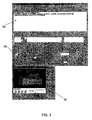
- FIG. 3 illustrates windows of a user interface for configuring an apparatus of one embodiment
- FIG. 4 is a flow chart illustrating embodiments of a method of remotely controlling a set-top box.
- Apparatuses and methods for remotely controlling set-top boxes are provided in accordance with various exemplary embodiments.
- a virtual remote controller is described for making selections and entering commands to control an associated set-top box.
- the virtual remote controller captures the appearance and configuration of the physical remote controller corresponding to the particular set-top box and emulates the physical remote controller in function, as well.
- a user may intuitively make selections using the virtual remote controller in the same way that the user makes selections on the physical remote controller, thereby greatly reducing the learning curve associated with remotely operating various set-top boxes.
- embodiments of the apparatus 10 comprise a memory device 12 and a processor 14 in communication with the memory device 12 .
- the memory device 12 is configured to store an image file defining an image of a set-top box remote controller and a plurality of signal files
- the processor 14 is configured to generate the image of the set-top box remote controller for display according to the image file.
- the apparatus 10 may also include a display 16 , and the processor 14 may be configured to generate the image of the set-top box remote controller upon the display 16 .
- a user of the apparatus 10 may be able to interact with the processor 14 to access the image file 13 and corresponding signal files 15 for the remote controller of a respective set top box 18 stored in the memory device 12 in order to command the respective set-top box 18 to perform an operation by causing an appropriate signal 17 to be transmitted from the apparatus 10 to the respective set-top box 18 .
- the processor 14 may also be configured to generate upon the display 16 an image corresponding to the operation of the respective set-top box 18 , as will be discussed below.
- the image 20 of the set-top box remote controller which is defined by the image file 13 , includes a plurality of remote controller buttons 22 and is configured to represent an actual, tangible remote controller associated with a particular set-top box.
- Each of the signal files 15 stored in the memory device 12 is configured to control an operation of a respective set-top box 18 and is associated with a respective button 22 in the image 20 of the set-top box remote controller.
- each signal file 15 is associated with a particular button 22 on a respective remote controller and defines a signal 17 that when presented to a respective set-top box 18 is: (1) identical to the signal transmitted by the conventional remote controller upon the user's depressing the associated button or (2) otherwise causes the same response action to be taken by the set-top box as if the respective remote controller had transmitted a signal in response to the user's depressing the associated button.
- the signal files 15 can be created in various ways. For example, an interface may be used to capture an Infra Red (IR) signal from the actual remote controller associated with a particular set-top box; in other words, the interface may capture the signal emitted by the actual remote controller when one of the actual buttons is depressed. The signal may then be digitized and recorded in a signal file 15 that is stored, along with other signal files 15 corresponding to the signals transmitted by the actual remote controller in response to actuation of the other buttons, in the memory device 12 . Alternatively, signal files 15 may be created through the manual entry of commands. Each signal file 15 may then be associated with the respective button 22 in the image 20 of the set-top box remote controller displayed by the processor 14 .
- IR Infra Red
- the signal generated by an actual remote controller when the PLAY button is depressed may be captured, digitized, and recorded in a signal file in the memory device 12 .
- the signal file 15 for the PLAY command is associated with the PLAY button 23 in the image 20 of the remote controller such that when a user selects the PLAY button 23 in the image 20 , the processor 14 is responsive to that selection and causes the signal 17 for the PLAY command, as defined by the recorded signal file 15 , to be transmitted to the respective set-top box 18 .
- the set-top box 18 Upon receiving the signal 17 , the set-top box 18 would perform the PLAY operation in generally the same manner that it would have performed the operation had the PLAY button on the actual remote controller been depressed.
- a remote user not having access to the physical remote controller such as a technician in his office troubleshooting a problem with a set-top box located at a remote subscriber location, may be able to command the set-top box to perform various operations and evaluate the results.
- the signal 17 generated by the apparatus 10 may be transmitted to the respective set-top box via a communications protocol, such as Transmission Control Protocol/Internet Protocol (TCP/IP).
- TCP/IP Transmission Control Protocol/Internet Protocol
- the signal 17 may then be converted to a format that is compatible with the set-top box 18 .
- the signal 17 may be converted from a TCP/IP signal to an IR signal, or from a TCP/IP signal to a serial device control protocol signal, such as RS-232, to be received by a serial port of the set-top box 18 .
- the apparatus 10 may be configured to generate an image 20 of a set-top box remote controller having various buttons 22 corresponding to the buttons of the actual remote controller of the respective set-top box 18 .
- the image 20 may have buttons 22 , each of which is identified to perform one of the following functions: play, stop, pause, fast forward, reverse, next chapter, previous chapter, menu, scroll up, scroll down, scroll left, scroll right, and select.
- the selection of one of these buttons 22 in the image 20 may then cause an associated signal 17 defined by a respective signal file to be transmitted to the respective set-top box 18 in order to perform the identified function.
- some of the above listed functions may not be included as buttons 22 in the image 20 , and numerous other functions not mentioned may be included.
- the image 20 of the remote controller may be inset in one window of a larger display, as shown in FIG. 2 .
- Other windows may also be displayed to facilitate the configuring of the virtual remote controller, either on the same screen as the window displaying the image 20 of the remote controller, or separately as shown in FIG. 3 .
- the auxiliary windows may, for example, include a text field 28 for displaying a string of commands being built and associated options for building the command string, as will be discussed below.
- options may include a static delay field 30 for specifying a period of time between the transmission of each signal to the respective set-top box, regardless of the time delay recorded by the user when the buttons 22 in the image 20 of the remote controller were selected.
- a static time delay of 8 seconds may be used as an input to simulate a delay of 8 seconds between each command, similar to a user waiting 8 seconds before depressing each subsequent button on a conventional remote controller.
- the time delay may be varied depending on the type of set-top box controlled and the capabilities of the set-top box to receive and implement a series of commands.
- a viewer 32 may be included to display video feedback from the respective set-top box 18 being controlled, such as during the construction of a command string, discussed below, or the execution of commands.
- the viewer 32 may allow a technician to view the content received at the set-top box, in the same manner that a subscriber may view content on a television associated with a set-top box as the subscriber is viewing a program guide or selecting a movie to view.
- the window in which the image 20 of the remote controller is displayed in some embodiments may also include other user input fields, such as buttons, check boxes, or the like, as shown in FIG. 2 .
- user input fields may be included, for example, for configuring the virtual remote controller and for facilitating the control of respective set-top boxes 18 .
- the exemplary buttons of the image shown in FIG. 2 include “command library” for displaying all available set-top box commands; “record” for taking a snapshot or continuously recording the operations of the set-top box; and “AC Power” for removing power from the respective set-top box 18 to simulate a power outage situation.
- a “scene check” button may also be provided for allowing a user to capture still-motion video scenes during the construction of a command string, for example to compare the scenes to reference video during the execution of the command string, such as to ensure that the correct channel was selected or the right movie was accessed.
- buttons shown in FIG. 2 also include “custom salvo” for accessing customized command strings for performing certain set-top box operations; “show buttons” for displaying the set-top box commands associated with the buttons 22 in the image 20 of the remote controller as well as accessing other commands for further associating the signal files 15 defining those commands with the displayed remote controller buttons 22 ; and “load picture” for accessing an image file 13 to display a particular image 20 of a set-top box remote controller.
- the exemplary embodiment includes check boxes for “live action” for transmitting the signals 17 corresponding to the signal files 15 associated with the buttons 22 selected in the image 20 ; “record delays” to record the time between each button 22 selection in addition to recording the command selected; and “build string” to facilitate building a string of commands by selecting a series of buttons 22 as will be discussed below, with or without transmitting the associated signals 17 to the respective set-top boxes 18 at the same time.
- the exemplary embodiment shown in FIG. 2 also includes a window to display the time between button selections and a window for specifying a respective set-top box.
- the apparatus 10 may further be configured to store one or more selections made by a user interacting with the buttons 22 of the image 20 .
- a technician may build a string of commands corresponding to more than one operation of the respective set-top box 18 by selecting more than one button 22 in a desired sequence and/or selecting a particular button 22 more than once.
- the technician may, for example, wish to command the set-top box 18 to display a Menu screen, scroll to a particular movie, select the movie, play the movie, then pause the movie.
- the technician may select the buttons 22 in the image 20 corresponding to the commands she wishes to make (MENU, SCROLL UP, SCROLL UP, SCROLL UP, SCROLL UP, SELECT, PLAY, PAUSE) and store the selections in a string of commands.
- the commands associated with the stored selections may be transmitted at the time the selections are made and remain available for future transmissions such as if the stored selections represent a batch process that is periodically performed for maintenance or diagnostic reasons. Alternatively, the technician may not wish to transmit the commands to the respective set-top box at the time the selections are made. Rather, the processor 14 may be configured to receive a user input defining a time for the associated signals 17 to be transmitted to the respective set-top box 18 . For example, as illustrated in FIG. 2 , the processor 14 may display an “Insert Delay” button 24 that, if selected by the user, allows the user to enter a time delay during which the apparatus 10 must wait before the signals 17 associated with the stored selections may be transmitted, such as a 2-hour delay. Other embodiments not pictured may allow a user to schedule a particular time for the stored selections to be executed (for example, at 2:00 A.M.).
- buttons 22 of the apparatus 10 may result in other functions of the processor 14 , as well.
- the processor 14 may be configured to present an indication of the operation performed by the respective set-top box 18 in response to a user's selection of buttons 22 .
- a user may view on the viewer 32 , shown in FIG. 3 , the content received at the set-top box 18 as a result of the executed commands. In this way, the technician may be able to evaluate whether the set-top box executed one or more operations in the required manner and address any problems.
- Other indications may be provided by the processor 14 , such as messages (“Command Successful” or “Command Failed”) generated on the display 16 , to indicate a status of the command transmitted to the respective set-top box 18 .
- buttons 22 may also result from the selection of buttons 22 , as provided in U.S. Ser. No. 11 / 620 , 158 , entitled “System for Testing Set-Top Boxes and Content Distribution Networks and Associated Methods”, filed on Jan. 5, 2007, the content of which is incorporated by reference herein in its entirety.
- the memory device 12 may be configured to store more than one image file 13 along with the signal files 15 associated with the buttons 22 of each image 20 defined by an image file 13 .
- This may allow image files 13 defining images 20 of different set-top box remote controllers, such as different makes and models of set-top box remote controllers, to be stored in the memory device 12 .
- the processor 14 may also be configured to receive a user's input as to which set-top box remote controller image 20 (and associated signal files 15 ) should be generated and displayed. For example, a technician may need to command a respective set-top box 18 that is controlled by an Acme2 model set-top box remote controller.
- the processor 14 may be configured to display a drop-down box 26 , for example, allowing a user to select an Acme2 remote controller.
- the processor 14 may be configured to receive the user's input regarding which image 20 is desired and access the corresponding image file 13 and signal files 15 to generate the appropriate image 20 .
- the apparatus 10 may be connected to more than one set-top box 18 , for example if the apparatus 10 is in communication with multiple set-top boxes 18 over the Internet.
- the processor 14 may be further configured to receive a user input to determine which of the accessible set-top boxes 18 is to be controlled.
- the processor 14 may be configured to receive a set-top box identifier, such as “STB5,” in a text box to determine which set-top box 18 to control.
- the processor 14 may be configured to display a list of accessible set-top boxes 18 , such as by listing the location of each device on the network. The user may then be able to select one of the accessible set-top boxes 18 , and the processor 14 would receive the input to determine to which of the accessible set-top boxes 18 the signals 17 should be sent.
- a method is also provided for remotely controlling set-top boxes.
- an image 20 of a remote controller configured to control a set-top box is initially displayed.
- the image 20 includes more than one button 22 , generally corresponding to buttons on the actual remote controller of the respective set-top box 18 .
- An input selecting one of the buttons 22 is then received, and a signal file 15 associated with the selected button 22 is determined.
- FIG. 4 blocks 100 - 104 .
- the input may be provided in various manners, but the processor may be configured to track the cursor position upon the image and to recognize selection of a button 22 upon user actuation of a user input device 19 , such as a mouse, keypad, or the like, while the cursor overlies the image of the respective button 22 .
- a user input device 19 such as a mouse, keypad, or the like
- a signal 17 defined by the signal file associated with the button 22 selected may then be transmitted to the respective set-top box.
- the signal 17 may be transmitted as an optical signal over an optical network, over an Internet connection through an Ethernet cable, or wirelessly via satellite. See block 106 .
- the signal 17 transmitted to the respective set-top box 18 may cause the set-top box 18 to perform one or more operations.
- the signal 17 may include a command to download video content from a main server and to play the content, such as a command to download and play a movie.
- the operation performed may then be displayed so that a user, such as a technician, may be able to evaluate the performance of the command. See block 108 .
- the movie to be downloaded and played may be displayed at the technician's location, rather than or in addition to being displayed at the subscriber's location, so that the technician may evaluate whether the commands were properly executed by the particular set-top box.
- a message may be displayed informing the technician that the operation requested was successfully executed.
- one or more inputs such as a string of selections
- the associated signals defined by the signal files 15 associated with the buttons 22 selected may be transmitted to the respective set-top box at a predetermined time. See blocks 110 - 112 .
- An input defining a time for transmitting the signals 17 may also be received. See block 114 .
- a technician may select various buttons 22 to command a set-top box to perform various functions, such as to download several movies.
- the technician may also provide a desired time at which the signals 17 associated with those selections should be transmitted.
- more than one image 20 corresponding to more than one set-top box remote controller, as well as the signal files 15 associated with the buttons 22 on each image 20 may be stored. See block 116 .
- different images 20 of set-top box remote controllers corresponding to different manufacturers and models of set-top boxes may be stored.
- Each image 20 may include different buttons 22 according to the particular model represented, and different signal files 15 may be associated with the buttons 22 of each image 20 .
- An input from the user, such as a technician may be received to determine which of the stored images should be displayed. See block 118 .
- the technician wishing to control an Acme2 model of set-top box may provide the model as an input, and the image 20 of the Acme2 set-top box remote controller may be displayed as a result.
- More than one set-top box may be accessible to a user desiring to remotely control a set-top box.
- an input from the user may be received to determine to which of the set-top boxes the signal 17 should be transmitted. See block 120 .
- a technician may have access to twenty set-top boxes but only have the need to control one of the accessible set-top boxes.
- the technician's input as to which set-top box should be controlled may be received to determine an appropriate pathway for the signal 17 .
- embodiments may take the form of hardware systems and/or apparatuses, software, or combinations thereof.
- embodiments may include a computer program product that includes a computer-readable storage medium (e.g., memory) and one or more executable portions (e.g., software) stored by the computer-readable storage medium for performing the operations described herein upon execution thereof.
- the executable portions may be stored in a memory 12 of the apparatus 10 of FIG. 1 such that the processor 14 may access and execute the executable portions of the computer program product in order to perform the functions described herein including, for example, those depicted in FIG. 4 .
Abstract
Description
Claims (26)
Priority Applications (1)
| Application Number | Priority Date | Filing Date | Title |
|---|---|---|---|
| US11/620,176 US8312495B2 (en) | 2007-01-05 | 2007-01-05 | Apparatus for remotely controlling set-top boxes and an associated method and computer program product |
Applications Claiming Priority (1)
| Application Number | Priority Date | Filing Date | Title |
|---|---|---|---|
| US11/620,176 US8312495B2 (en) | 2007-01-05 | 2007-01-05 | Apparatus for remotely controlling set-top boxes and an associated method and computer program product |
Publications (2)
| Publication Number | Publication Date |
|---|---|
| US20080166105A1 US20080166105A1 (en) | 2008-07-10 |
| US8312495B2 true US8312495B2 (en) | 2012-11-13 |
Family
ID=39594376
Family Applications (1)
| Application Number | Title | Priority Date | Filing Date |
|---|---|---|---|
| US11/620,176 Active 2028-06-26 US8312495B2 (en) | 2007-01-05 | 2007-01-05 | Apparatus for remotely controlling set-top boxes and an associated method and computer program product |
Country Status (1)
| Country | Link |
|---|---|
| US (1) | US8312495B2 (en) |
Cited By (27)
| Publication number | Priority date | Publication date | Assignee | Title |
|---|---|---|---|---|
| US20110251820A1 (en) * | 2010-04-09 | 2011-10-13 | Mitsumi Electric Co., Ltd. | Evaluation system, evaluation device, evaluation method, and recording medium |
| US20150268648A1 (en) * | 2014-03-24 | 2015-09-24 | Xiaomi Inc. | Method and terminal device for controlling smart home appliance |
| US9620312B2 (en) | 2013-08-09 | 2017-04-11 | Apple Inc. | Tactile switch for an electronic device |
| US9753436B2 (en) | 2013-06-11 | 2017-09-05 | Apple Inc. | Rotary input mechanism for an electronic device |
| US9891651B2 (en) | 2016-02-27 | 2018-02-13 | Apple Inc. | Rotatable input mechanism having adjustable output |
| US9952558B2 (en) | 2015-03-08 | 2018-04-24 | Apple Inc. | Compressible seal for rotatable and translatable input mechanisms |
| US10018966B2 (en) | 2015-04-24 | 2018-07-10 | Apple Inc. | Cover member for an input mechanism of an electronic device |
| US10019097B2 (en) | 2016-07-25 | 2018-07-10 | Apple Inc. | Force-detecting input structure |
| US10048802B2 (en) | 2014-02-12 | 2018-08-14 | Apple Inc. | Rejection of false turns of rotary inputs for electronic devices |
| US10055030B2 (en) | 2013-05-17 | 2018-08-21 | Apple Inc. | Dynamic visual indications for input devices |
| US10061399B2 (en) | 2016-07-15 | 2018-08-28 | Apple Inc. | Capacitive gap sensor ring for an input device |
| US10145711B2 (en) | 2015-03-05 | 2018-12-04 | Apple Inc. | Optical encoder with direction-dependent optical properties having an optically anisotropic region to produce a first and a second light distribution |
| US10190891B1 (en) | 2014-07-16 | 2019-01-29 | Apple Inc. | Optical encoder for detecting rotational and axial movement |
| US10551798B1 (en) | 2016-05-17 | 2020-02-04 | Apple Inc. | Rotatable crown for an electronic device |
| US10599101B2 (en) | 2014-09-02 | 2020-03-24 | Apple Inc. | Wearable electronic device |
| US10664074B2 (en) | 2017-06-19 | 2020-05-26 | Apple Inc. | Contact-sensitive crown for an electronic watch |
| US10726269B2 (en) | 2017-07-20 | 2020-07-28 | Verizon Patent And Licensing, Inc. | Aligning advertisements in video streams |
| US10962935B1 (en) | 2017-07-18 | 2021-03-30 | Apple Inc. | Tri-axis force sensor |
| US11181863B2 (en) | 2018-08-24 | 2021-11-23 | Apple Inc. | Conductive cap for watch crown |
| US11194299B1 (en) | 2019-02-12 | 2021-12-07 | Apple Inc. | Variable frictional feedback device for a digital crown of an electronic watch |
| US11194298B2 (en) | 2018-08-30 | 2021-12-07 | Apple Inc. | Crown assembly for an electronic watch |
| US11269376B2 (en) | 2020-06-11 | 2022-03-08 | Apple Inc. | Electronic device |
| US11360440B2 (en) | 2018-06-25 | 2022-06-14 | Apple Inc. | Crown for an electronic watch |
| US11550268B2 (en) | 2020-06-02 | 2023-01-10 | Apple Inc. | Switch module for electronic crown assembly |
| US11561515B2 (en) | 2018-08-02 | 2023-01-24 | Apple Inc. | Crown for an electronic watch |
| US11796968B2 (en) | 2018-08-30 | 2023-10-24 | Apple Inc. | Crown assembly for an electronic watch |
| US11796961B2 (en) | 2018-08-24 | 2023-10-24 | Apple Inc. | Conductive cap for watch crown |
Families Citing this family (14)
| Publication number | Priority date | Publication date | Assignee | Title |
|---|---|---|---|---|
| US7774821B2 (en) * | 2007-09-17 | 2010-08-10 | At&T Intellectual Property I, L.P. | System and method of installing a network device |
| JP5042050B2 (en) * | 2008-01-25 | 2012-10-03 | シャープ株式会社 | Television receiver, server, television receiver operating system, and television receiver operating program |
| US9870123B1 (en) | 2008-04-18 | 2018-01-16 | Universal Electronics Inc. | Selecting a picture of a device to identify an associated codeset |
| JP5100595B2 (en) * | 2008-09-30 | 2012-12-19 | シャープ株式会社 | AV equipment, server, AV equipment operating system, and AV equipment operating program |
| US8661487B2 (en) * | 2009-10-12 | 2014-02-25 | At&T Intellectual Property I, L.P. | Accessing remote video devices |
| GB2483499A (en) * | 2010-09-10 | 2012-03-14 | S3 Res & Dev Ltd | Diagnostics and Analysis of a Set Top Box |
| US20120068857A1 (en) * | 2010-09-22 | 2012-03-22 | Apple Inc. | Configurable remote control |
| US8719581B2 (en) | 2010-09-22 | 2014-05-06 | Savant Systems, Llc | Programmable multimedia controller with flexible user access and shared device configurations |
| KR101781640B1 (en) * | 2011-02-14 | 2017-09-25 | 엘지전자 주식회사 | Method for providing remote control service and display apparatus thereof |
| US9432608B2 (en) * | 2012-03-29 | 2016-08-30 | Lg Electronics Inc. | Multimedia device connected to at least one electronic device and controling method thereof |
| US9253547B2 (en) * | 2012-10-31 | 2016-02-02 | Verizon Patent And Licensing Inc. | Methods and systems for facilitating remote control of a television by a support technician |
| US9367144B2 (en) * | 2013-03-13 | 2016-06-14 | Google Inc. | Methods, systems, and media for providing a remote control interface for a media playback device |
| CN105100863A (en) | 2014-04-28 | 2015-11-25 | 阿里巴巴集团控股有限公司 | Television channel switching method and system, mobile terminal and set top box |
| US11564009B2 (en) * | 2018-06-25 | 2023-01-24 | Intraway R&D S.A. | System and method for interactive set top box setup |
Citations (18)
| Publication number | Priority date | Publication date | Assignee | Title |
|---|---|---|---|---|
| US4825200A (en) * | 1987-06-25 | 1989-04-25 | Tandy Corporation | Reconfigurable remote control transmitter |
| US5781720A (en) * | 1992-11-19 | 1998-07-14 | Segue Software, Inc. | Automated GUI interface testing |
| US5790117A (en) * | 1992-11-02 | 1998-08-04 | Borland International, Inc. | System and methods for improved program testing |
| US6091882A (en) * | 1988-12-23 | 2000-07-18 | Gemstar Development Corporation | Apparatus and method using compressed codes for recorder preprogramming |
| US6229433B1 (en) * | 1999-07-30 | 2001-05-08 | X-10 Ltd. | Appliance control |
| US20010056576A1 (en) * | 2000-05-18 | 2001-12-27 | Joong-Je Park | Apparatus and method for receiving multichannel signals |
| US20020087949A1 (en) * | 2000-03-03 | 2002-07-04 | Valery Golender | System and method for software diagnostics using a combination of visual and dynamic tracing |
| US20020194596A1 (en) * | 2001-06-18 | 2002-12-19 | Srivastava Gopal K. | Control of multiple AV-devices by a single master controller using infrared transmitted commands and bus transmitted commands |
| US20030056215A1 (en) * | 1998-11-30 | 2003-03-20 | Rajesh Kanungo | Tv pip using java api classes and java implementation classes |
| US20040172621A1 (en) * | 2001-07-05 | 2004-09-02 | Guillorit Fabien Marcel Jacques | System with macro commands |
| US20040207535A1 (en) * | 2002-05-30 | 2004-10-21 | Stevenson George E. | System and method for learning macro routines in a remote control |
| US20050183128A1 (en) * | 2004-02-18 | 2005-08-18 | Inter-Cite Video Inc. | System and method for the automated, remote diagnostic of the operation of a digital video recording network |
| US20050179558A1 (en) * | 2004-02-13 | 2005-08-18 | Williams Don P. | Method and apparatus for remote control of electronic equipment |
| US20060020962A1 (en) * | 2004-04-30 | 2006-01-26 | Vulcan Inc. | Time-based graphical user interface for multimedia content |
| US20060064720A1 (en) * | 2004-04-30 | 2006-03-23 | Vulcan Inc. | Controlling one or more media devices |
| US20060085579A1 (en) * | 2004-10-14 | 2006-04-20 | Sony Corporation | Remote control system, remote control method, remote controller, and electronic device |
| US20060095472A1 (en) * | 2004-06-07 | 2006-05-04 | Jason Krikorian | Fast-start streaming and buffering of streaming content for personal media player |
| US20080010482A1 (en) * | 2006-06-13 | 2008-01-10 | Microsoft Corporation | Remote control of a media computing device |
-
2007
- 2007-01-05 US US11/620,176 patent/US8312495B2/en active Active
Patent Citations (18)
| Publication number | Priority date | Publication date | Assignee | Title |
|---|---|---|---|---|
| US4825200A (en) * | 1987-06-25 | 1989-04-25 | Tandy Corporation | Reconfigurable remote control transmitter |
| US6091882A (en) * | 1988-12-23 | 2000-07-18 | Gemstar Development Corporation | Apparatus and method using compressed codes for recorder preprogramming |
| US5790117A (en) * | 1992-11-02 | 1998-08-04 | Borland International, Inc. | System and methods for improved program testing |
| US5781720A (en) * | 1992-11-19 | 1998-07-14 | Segue Software, Inc. | Automated GUI interface testing |
| US20030056215A1 (en) * | 1998-11-30 | 2003-03-20 | Rajesh Kanungo | Tv pip using java api classes and java implementation classes |
| US6229433B1 (en) * | 1999-07-30 | 2001-05-08 | X-10 Ltd. | Appliance control |
| US20020087949A1 (en) * | 2000-03-03 | 2002-07-04 | Valery Golender | System and method for software diagnostics using a combination of visual and dynamic tracing |
| US20010056576A1 (en) * | 2000-05-18 | 2001-12-27 | Joong-Je Park | Apparatus and method for receiving multichannel signals |
| US20020194596A1 (en) * | 2001-06-18 | 2002-12-19 | Srivastava Gopal K. | Control of multiple AV-devices by a single master controller using infrared transmitted commands and bus transmitted commands |
| US20040172621A1 (en) * | 2001-07-05 | 2004-09-02 | Guillorit Fabien Marcel Jacques | System with macro commands |
| US20040207535A1 (en) * | 2002-05-30 | 2004-10-21 | Stevenson George E. | System and method for learning macro routines in a remote control |
| US20050179558A1 (en) * | 2004-02-13 | 2005-08-18 | Williams Don P. | Method and apparatus for remote control of electronic equipment |
| US20050183128A1 (en) * | 2004-02-18 | 2005-08-18 | Inter-Cite Video Inc. | System and method for the automated, remote diagnostic of the operation of a digital video recording network |
| US20060020962A1 (en) * | 2004-04-30 | 2006-01-26 | Vulcan Inc. | Time-based graphical user interface for multimedia content |
| US20060064720A1 (en) * | 2004-04-30 | 2006-03-23 | Vulcan Inc. | Controlling one or more media devices |
| US20060095472A1 (en) * | 2004-06-07 | 2006-05-04 | Jason Krikorian | Fast-start streaming and buffering of streaming content for personal media player |
| US20060085579A1 (en) * | 2004-10-14 | 2006-04-20 | Sony Corporation | Remote control system, remote control method, remote controller, and electronic device |
| US20080010482A1 (en) * | 2006-06-13 | 2008-01-10 | Microsoft Corporation | Remote control of a media computing device |
Cited By (79)
| Publication number | Priority date | Publication date | Assignee | Title |
|---|---|---|---|---|
| US20110251820A1 (en) * | 2010-04-09 | 2011-10-13 | Mitsumi Electric Co., Ltd. | Evaluation system, evaluation device, evaluation method, and recording medium |
| US10795460B2 (en) | 2013-05-17 | 2020-10-06 | Apple Inc. | Dynamic visual indications for input devices |
| US10055030B2 (en) | 2013-05-17 | 2018-08-21 | Apple Inc. | Dynamic visual indications for input devices |
| US11353969B2 (en) | 2013-05-17 | 2022-06-07 | Apple Inc. | Dynamic visual indications for input devices |
| US11531306B2 (en) | 2013-06-11 | 2022-12-20 | Apple Inc. | Rotary input mechanism for an electronic device |
| US10234828B2 (en) | 2013-06-11 | 2019-03-19 | Apple Inc. | Rotary input mechanism for an electronic device |
| US9753436B2 (en) | 2013-06-11 | 2017-09-05 | Apple Inc. | Rotary input mechanism for an electronic device |
| US9886006B2 (en) | 2013-06-11 | 2018-02-06 | Apple Inc. | Rotary input mechanism for an electronic device |
| US10216147B2 (en) | 2013-08-09 | 2019-02-26 | Apple Inc. | Tactile switch for an electronic device |
| US9620312B2 (en) | 2013-08-09 | 2017-04-11 | Apple Inc. | Tactile switch for an electronic device |
| US10732571B2 (en) | 2013-08-09 | 2020-08-04 | Apple Inc. | Tactile switch for an electronic device |
| US9971305B2 (en) | 2013-08-09 | 2018-05-15 | Apple Inc. | Tactile switch for an electronic device |
| US11886149B2 (en) | 2013-08-09 | 2024-01-30 | Apple Inc. | Tactile switch for an electronic device |
| US9836025B2 (en) | 2013-08-09 | 2017-12-05 | Apple Inc. | Tactile switch for an electronic device |
| US10331081B2 (en) | 2013-08-09 | 2019-06-25 | Apple Inc. | Tactile switch for an electronic device |
| US10331082B2 (en) | 2013-08-09 | 2019-06-25 | Apple Inc. | Tactile switch for an electronic device |
| US9709956B1 (en) | 2013-08-09 | 2017-07-18 | Apple Inc. | Tactile switch for an electronic device |
| US9627163B2 (en) | 2013-08-09 | 2017-04-18 | Apple Inc. | Tactile switch for an electronic device |
| US10962930B2 (en) | 2013-08-09 | 2021-03-30 | Apple Inc. | Tactile switch for an electronic device |
| US10175652B2 (en) | 2013-08-09 | 2019-01-08 | Apple Inc. | Tactile switch for an electronic device |
| US10613685B2 (en) | 2014-02-12 | 2020-04-07 | Apple Inc. | Rejection of false turns of rotary inputs for electronic devices |
| US10222909B2 (en) | 2014-02-12 | 2019-03-05 | Apple Inc. | Rejection of false turns of rotary inputs for electronic devices |
| US10884549B2 (en) | 2014-02-12 | 2021-01-05 | Apple Inc. | Rejection of false turns of rotary inputs for electronic devices |
| US10048802B2 (en) | 2014-02-12 | 2018-08-14 | Apple Inc. | Rejection of false turns of rotary inputs for electronic devices |
| US11347351B2 (en) | 2014-02-12 | 2022-05-31 | Apple Inc. | Rejection of false turns of rotary inputs for electronic devices |
| US11669205B2 (en) | 2014-02-12 | 2023-06-06 | Apple Inc. | Rejection of false turns of rotary inputs for electronic devices |
| US9952571B2 (en) * | 2014-03-24 | 2018-04-24 | Xiaomi Inc. | Method and terminal device for controlling smart home appliance |
| US20150268648A1 (en) * | 2014-03-24 | 2015-09-24 | Xiaomi Inc. | Method and terminal device for controlling smart home appliance |
| US10190891B1 (en) | 2014-07-16 | 2019-01-29 | Apple Inc. | Optical encoder for detecting rotational and axial movement |
| US11015960B2 (en) | 2014-07-16 | 2021-05-25 | Apple Inc. | Optical encoder for detecting crown movement |
| US11221590B2 (en) | 2014-09-02 | 2022-01-11 | Apple Inc. | Wearable electronic device |
| US10942491B2 (en) | 2014-09-02 | 2021-03-09 | Apple Inc. | Wearable electronic device |
| US11762342B2 (en) | 2014-09-02 | 2023-09-19 | Apple Inc. | Wearable electronic device |
| US10599101B2 (en) | 2014-09-02 | 2020-03-24 | Apple Inc. | Wearable electronic device |
| US11567457B2 (en) | 2014-09-02 | 2023-01-31 | Apple Inc. | Wearable electronic device |
| US10613485B2 (en) | 2014-09-02 | 2020-04-07 | Apple Inc. | Wearable electronic device |
| US10620591B2 (en) | 2014-09-02 | 2020-04-14 | Apple Inc. | Wearable electronic device |
| US10627783B2 (en) | 2014-09-02 | 2020-04-21 | Apple Inc. | Wearable electronic device |
| US11474483B2 (en) | 2014-09-02 | 2022-10-18 | Apple Inc. | Wearable electronic device |
| US10655988B2 (en) | 2015-03-05 | 2020-05-19 | Apple Inc. | Watch with rotatable optical encoder having a spindle defining an array of alternating regions extending along an axial direction parallel to the axis of a shaft |
| US10145711B2 (en) | 2015-03-05 | 2018-12-04 | Apple Inc. | Optical encoder with direction-dependent optical properties having an optically anisotropic region to produce a first and a second light distribution |
| US11002572B2 (en) | 2015-03-05 | 2021-05-11 | Apple Inc. | Optical encoder with direction-dependent optical properties comprising a spindle having an array of surface features defining a concave contour along a first direction and a convex contour along a second direction |
| US10845764B2 (en) | 2015-03-08 | 2020-11-24 | Apple Inc. | Compressible seal for rotatable and translatable input mechanisms |
| US9952558B2 (en) | 2015-03-08 | 2018-04-24 | Apple Inc. | Compressible seal for rotatable and translatable input mechanisms |
| US10037006B2 (en) | 2015-03-08 | 2018-07-31 | Apple Inc. | Compressible seal for rotatable and translatable input mechanisms |
| US10222756B2 (en) | 2015-04-24 | 2019-03-05 | Apple Inc. | Cover member for an input mechanism of an electronic device |
| US10018966B2 (en) | 2015-04-24 | 2018-07-10 | Apple Inc. | Cover member for an input mechanism of an electronic device |
| US9891651B2 (en) | 2016-02-27 | 2018-02-13 | Apple Inc. | Rotatable input mechanism having adjustable output |
| US10579090B2 (en) | 2016-02-27 | 2020-03-03 | Apple Inc. | Rotatable input mechanism having adjustable output |
| US10551798B1 (en) | 2016-05-17 | 2020-02-04 | Apple Inc. | Rotatable crown for an electronic device |
| US10061399B2 (en) | 2016-07-15 | 2018-08-28 | Apple Inc. | Capacitive gap sensor ring for an input device |
| US10379629B2 (en) | 2016-07-15 | 2019-08-13 | Apple Inc. | Capacitive gap sensor ring for an electronic watch |
| US10955937B2 (en) | 2016-07-15 | 2021-03-23 | Apple Inc. | Capacitive gap sensor ring for an input device |
| US10509486B2 (en) | 2016-07-15 | 2019-12-17 | Apple Inc. | Capacitive gap sensor ring for an electronic watch |
| US11513613B2 (en) | 2016-07-15 | 2022-11-29 | Apple Inc. | Capacitive gap sensor ring for an input device |
| US11720064B2 (en) | 2016-07-25 | 2023-08-08 | Apple Inc. | Force-detecting input structure |
| US10296125B2 (en) | 2016-07-25 | 2019-05-21 | Apple Inc. | Force-detecting input structure |
| US10948880B2 (en) | 2016-07-25 | 2021-03-16 | Apple Inc. | Force-detecting input structure |
| US10019097B2 (en) | 2016-07-25 | 2018-07-10 | Apple Inc. | Force-detecting input structure |
| US10572053B2 (en) | 2016-07-25 | 2020-02-25 | Apple Inc. | Force-detecting input structure |
| US11385599B2 (en) | 2016-07-25 | 2022-07-12 | Apple Inc. | Force-detecting input structure |
| US10664074B2 (en) | 2017-06-19 | 2020-05-26 | Apple Inc. | Contact-sensitive crown for an electronic watch |
| US10962935B1 (en) | 2017-07-18 | 2021-03-30 | Apple Inc. | Tri-axis force sensor |
| US10726269B2 (en) | 2017-07-20 | 2020-07-28 | Verizon Patent And Licensing, Inc. | Aligning advertisements in video streams |
| US11042752B2 (en) | 2017-07-20 | 2021-06-22 | Verizon Patent And Licensing Inc. | Aligning advertisements in video streams |
| US11754981B2 (en) | 2018-06-25 | 2023-09-12 | Apple Inc. | Crown for an electronic watch |
| US11360440B2 (en) | 2018-06-25 | 2022-06-14 | Apple Inc. | Crown for an electronic watch |
| US11906937B2 (en) | 2018-08-02 | 2024-02-20 | Apple Inc. | Crown for an electronic watch |
| US11561515B2 (en) | 2018-08-02 | 2023-01-24 | Apple Inc. | Crown for an electronic watch |
| US11796961B2 (en) | 2018-08-24 | 2023-10-24 | Apple Inc. | Conductive cap for watch crown |
| US11181863B2 (en) | 2018-08-24 | 2021-11-23 | Apple Inc. | Conductive cap for watch crown |
| US11796968B2 (en) | 2018-08-30 | 2023-10-24 | Apple Inc. | Crown assembly for an electronic watch |
| US11194298B2 (en) | 2018-08-30 | 2021-12-07 | Apple Inc. | Crown assembly for an electronic watch |
| US11194299B1 (en) | 2019-02-12 | 2021-12-07 | Apple Inc. | Variable frictional feedback device for a digital crown of an electronic watch |
| US11860587B2 (en) | 2019-02-12 | 2024-01-02 | Apple Inc. | Variable frictional feedback device for a digital crown of an electronic watch |
| US11815860B2 (en) | 2020-06-02 | 2023-11-14 | Apple Inc. | Switch module for electronic crown assembly |
| US11550268B2 (en) | 2020-06-02 | 2023-01-10 | Apple Inc. | Switch module for electronic crown assembly |
| US11635786B2 (en) | 2020-06-11 | 2023-04-25 | Apple Inc. | Electronic optical sensing device |
| US11269376B2 (en) | 2020-06-11 | 2022-03-08 | Apple Inc. | Electronic device |
Also Published As
| Publication number | Publication date |
|---|---|
| US20080166105A1 (en) | 2008-07-10 |
Similar Documents
| Publication | Publication Date | Title |
|---|---|---|
| US8312495B2 (en) | Apparatus for remotely controlling set-top boxes and an associated method and computer program product | |
| US20090100474A1 (en) | Remote control based output selection | |
| US8438589B2 (en) | Obtaining metadata program information during channel changes | |
| CN101646992B (en) | Content reproduction system, content reproduction/control device | |
| US8275857B2 (en) | Remote session recording apparatus and method | |
| US9389763B2 (en) | System for presenting media programs | |
| US20070055390A1 (en) | Extensible universal home automation integration framework and user interface | |
| US20120194442A1 (en) | Touch screen video source control system | |
| KR20080007461A (en) | Real-time hd tv/video ip streaming to a game console | |
| US20090070696A1 (en) | System and Method for Programming a Remote Control Device | |
| US8959552B2 (en) | Systems and methods to perform actions upon content items associated with multiple series subscriptions | |
| US10097876B2 (en) | Apparatus and method for providing media services | |
| KR101112186B1 (en) | Method and apparatus for providing dynamic display of content information associated with a device in a network | |
| US10187702B2 (en) | Systems and methods to test media devices | |
| US20160373799A1 (en) | Remote monitoring and control of multiple iptv client devices | |
| CN102347839A (en) | Content signaturing | |
| CN113242444A (en) | Display device, server and media asset playing method | |
| US20080246733A1 (en) | TV interface control system and method with automatic text entry | |
| JP2007524295A (en) | System and method for entering preferences into a recommender / profiling system | |
| US9392206B2 (en) | Methods and systems for providing auxiliary viewing options | |
| CN101753903A (en) | Method for displaying menu on electronic equipment and electronic equipment | |
| CN101127823A (en) | Control device and method for multiple controllers | |
| EP2458850A1 (en) | Program presentation apparatus and method | |
| US20100165196A1 (en) | Av presentation system including an rcu for controlling at least one av presentation device | |
| KR100935303B1 (en) | Method for linking among related services in internet protocol television service system services and internet protocol television service system for materializing the same |
Legal Events
| Date | Code | Title | Description |
|---|---|---|---|
| AS | Assignment |
Owner name: VERIZON SERVICES CORP., VIRGINIA Free format text: ASSIGNMENT OF ASSIGNORS INTEREST;ASSIGNOR:VANDERHOFF, EARL W.;REEL/FRAME:018715/0364 Effective date: 20061218 |
|
| AS | Assignment |
Owner name: VERIZON PATENT AND LICENSING INC., NEW JERSEY Free format text: ASSIGNMENT OF ASSIGNORS INTEREST;ASSIGNOR:VERIZON SERVICES CORP.;REEL/FRAME:023455/0611 Effective date: 20090801 Owner name: VERIZON PATENT AND LICENSING INC.,NEW JERSEY Free format text: ASSIGNMENT OF ASSIGNORS INTEREST;ASSIGNOR:VERIZON SERVICES CORP.;REEL/FRAME:023455/0611 Effective date: 20090801 |
|
| STCF | Information on status: patent grant |
Free format text: PATENTED CASE |
|
| FPAY | Fee payment |
Year of fee payment: 4 |
|
| MAFP | Maintenance fee payment |
Free format text: PAYMENT OF MAINTENANCE FEE, 8TH YEAR, LARGE ENTITY (ORIGINAL EVENT CODE: M1552); ENTITY STATUS OF PATENT OWNER: LARGE ENTITY Year of fee payment: 8 |