US8317421B2 - Tape drive tension control - Google Patents
Tape drive tension control Download PDFInfo
- Publication number
- US8317421B2 US8317421B2 US12/058,829 US5882908A US8317421B2 US 8317421 B2 US8317421 B2 US 8317421B2 US 5882908 A US5882908 A US 5882908A US 8317421 B2 US8317421 B2 US 8317421B2
- Authority
- US
- United States
- Prior art keywords
- tape
- tension
- motors
- motor
- spool
- Prior art date
- Legal status (The legal status is an assumption and is not a legal conclusion. Google has not performed a legal analysis and makes no representation as to the accuracy of the status listed.)
- Active, expires
Links
Images


Classifications
-
- B—PERFORMING OPERATIONS; TRANSPORTING
- B41—PRINTING; LINING MACHINES; TYPEWRITERS; STAMPS
- B41J—TYPEWRITERS; SELECTIVE PRINTING MECHANISMS, i.e. MECHANISMS PRINTING OTHERWISE THAN FROM A FORME; CORRECTION OF TYPOGRAPHICAL ERRORS
- B41J33/00—Apparatus or arrangements for feeding ink ribbons or like character-size impression-transfer material
- B41J33/14—Ribbon-feed devices or mechanisms
- B41J33/34—Ribbon-feed devices or mechanisms driven by motors independently of the machine as a whole
-
- G—PHYSICS
- G11—INFORMATION STORAGE
- G11B—INFORMATION STORAGE BASED ON RELATIVE MOVEMENT BETWEEN RECORD CARRIER AND TRANSDUCER
- G11B15/00—Driving, starting or stopping record carriers of filamentary or web form; Driving both such record carriers and heads; Guiding such record carriers or containers therefor; Control thereof; Control of operating function
- G11B15/18—Driving; Starting; Stopping; Arrangements for control or regulation thereof
- G11B15/43—Control or regulation of mechanical tension of record carrier, e.g. tape tension
-
- G—PHYSICS
- G11—INFORMATION STORAGE
- G11B—INFORMATION STORAGE BASED ON RELATIVE MOVEMENT BETWEEN RECORD CARRIER AND TRANSDUCER
- G11B15/00—Driving, starting or stopping record carriers of filamentary or web form; Driving both such record carriers and heads; Guiding such record carriers or containers therefor; Control thereof; Control of operating function
- G11B15/18—Driving; Starting; Stopping; Arrangements for control or regulation thereof
- G11B15/46—Controlling, regulating, or indicating speed
Definitions
- the present invention relates to a tape drive.
- a tape drive may form part of printing apparatus.
- such a tape drive may be used in transfer printers, that is, printers which make use of carrier-supported inks.
- a tape which is normally referred to as a printer tape and carries ink on one side is presented within a printer such that a printhead can contact the other side of the tape to cause the ink to be transferred from the tape on to a target substrate of, for example, paper or a flexible film.
- printers are used in many applications.
- Industrial printing applications include thermal transfer label printers and thermal transfer coders which print directly on to a substrate such as packaging materials manufactured from flexible film or card.
- Ink tape is normally delivered to the end user in the form of a roll wound onto a core.
- the end user pushes the core on to a tape spool, pulls a free end of the roll to release a length of tape, and then engages the end of the tape with a further spool.
- the spools may be mounted on a cassette, which can be readily mounted on a printing machine.
- the printing machine includes a transport means for driving the spools, so as to unwind tape from one spool and to take up tape on the other spool.
- the printing apparatus transports tape between the two spools along a predetermined path past the printhead.
- Known printers of the above type rely upon a wide range of different approaches to the problem of how to drive the tape spools. Some rely upon stepper motors operating in a position control mode to pay out or take-up a predetermined quantity of tape. Other known printers rely on DC motors operating in a torque mode to provide tension in the tape and to directly or indirectly drive the spools. Some known arrangements drive only the spool on to which tape is taken up (the take-up spool) and rely upon some form of “slipping clutch” arrangement on the spool from which tape is drawn (the supply spool) to provide a resistive drag force so as to ensure that the tape is maintained in tension during the printing and tape winding processes and to prevent tape overrun when the tape is brought to rest. It will be appreciated that maintaining adequate tension is an essential requirement for the proper functioning of the printer.
- a supply spool motor may be arranged to apply a predetermined drag to the tape, by being driven in the reverse direction to the direction of tape transport.
- the motor connected to the take-up spool is arranged to apply a greater force to the tape than the motor connected to the supply spool such that the supply spool motor is overpowered and the supply spool thus rotates in the direction of tape transport.
- the supply spool drag motor keeps the tape tensioned in normal operation.
- a supply spool motor may be driven in the direction of tape transport such that it contributes to driving the tape from the supply spool to the take-up spool.
- Such an arrangement is referred to herein as “push-pull”.
- the take-up motor pulls the tape onto the take-up spool as tape is unwound by the supply spool motor such that tape tension is maintained.
- Such a push-pull arrangement is described in our earlier UK patent number GB 2369602, which discloses the use of a pair of stepper motors to drive the supply spool and the take-up spool.
- a controller is arranged to control the energisation of the motors such that the tape may be transported in both directions between spools of tape.
- the tension in the tape being transported between spools is monitored and the motors are controlled to energise both motors to drive the spools of tape in the direction of tape transport.
- the variation in spool diameters can make it difficult to determine the correct drive signal to be supplied to each motor such that tape tension is maintained, and/or that tape is unwound or rewound at the correct rate.
- printer designs offer a compromise in performance by way of limiting the rate of acceleration, the rate of deceleration, or the maximum speed capability of the tape transport system. Overall printer performance has, as a result, been compromised in some cases.
- Known tape drive systems generally operate in one of two manners, that is either continuous printing or intermittent printing. In both modes of operation, the apparatus performs a regularly repeated series of printing cycles, each cycle including a printing phase during which ink is being transferred to a substrate, and a further non-printing phase during which the apparatus is prepared for the printing phase of the next cycle.
- a stationary printhead is brought into contact with a printer tape the other side of which is in contact with a substrate on to which an image is to be printed.
- the term “stationary” is used in the context of continuous printing to indicate that although the printhead will be moved into and out of contact with the tape, it will not move relative to the tape path in the direction in which tape is advanced along that path.
- both the substrate and tape are transported past the printhead, generally but not necessarily at the same speed.
- the printhead is extended into contact with the tape only when the printhead is adjacent to regions of the substrate to be printed.
- the tape must be accelerated up to, for example, the speed of travel of the substrate. The tape speed must then be maintained at the constant speed of the substrate during the printing phase and, after the printing phase has been completed, the tape must be decelerated and then driven in the reverse direction so that the used region of the tape is on the upstream side of the printhead.
- the tape must then be accelerated back up to the normal printing speed and the tape must be positioned so that an unused portion of the tape close to the previously used region of the tape is located between the printhead and the substrate when the printhead is advanced to the printing position.
- very rapid acceleration and deceleration of the tape in both directions is required, and the tape drive system must be capable of accurately locating the tape so as to avoid a printing operation being conducted when a previously used portion of the tape is interposed between the printhead and the substrate.
- a substrate is advanced past a printhead in a stepwise manner such that during the printing phase of each cycle the substrate and generally but not necessarily the tape, are stationary. Relative movement between the substrate, tape and printhead are achieved by displacing the printhead relative to the substrate and tape. Between the printing phase of successive cycles, the substrate is advanced so as to present the next region to be printed beneath the printhead, and the tape is advanced so that an unused section of tape is located between the printhead and the substrate. Once again rapid and accurate transport of the tape is necessary to ensure that unused tape is always located between the substrate and printhead at a time that the printhead is advanced to conduct a printing operation.
- tape drives in accordance with embodiments of the present invention are suitable for use in labelling machines in which labels are detached from a continuous label web which is transported between a supply spool and a take-up spool.
- a tape drive comprising two motors, two tape spool supports on which spools of tape may be mounted, each spool being drivable by a respective one of said motors, and a controller for controlling the energization of the motors such that the tape may be transported in at least one direction between spools mounted on the spool supports, wherein the controller is configured to store a plurality of motor control data items, each data item being associated with a respective tension value, and the controller is operative to: monitor tension in a tape being transported between spools mounted on the spool supports, read a motor control data item based upon said monitored tension, generate a motor control signal based upon said read motor control data item, and apply said motor control signal to at least one of the motors.
- the controller may be configured to processes the monitored tension and the predetermined target tension to determine an error signal. This processing may involve a subtraction operation. Having generated such an error signal the motor control data item may be obtained based upon the error signal.
- the predetermined target tension may be a range of tension values, referred to as a so-called “deadband.”
- the controller may be configured to further monitor tape tension. At least one stored motor control data item may be modified based upon the further monitoring. Specifically, if it is determined that the motor control signal did not correctly adjust tape tension the motor control data item may be modified so as to improve future performance.
- the controller may be configured to implement a configuration process, the configuration process being intended to store the motor control data items. Specifically, the process may involve determining relationships between changes in tension in the tape transported between the spools and motor control signals applied to the motors.
- At least one of the motors may be a position controlled motor such as a stepper motor.
- Each of the motor control data items may represent an angular position adjustment, for example an adjustment in terms of a number of steps.
- the controller may be adapted to energise both motors to drive spools of tape in the direction of tape transport.
- the controller may be configured to maintain tension in a tape between the spools between predetermined limits.
- the controller may be arranged to control the motor to transport tapes in both directions between the spools. That is, the tape drive may be bi-directional.
- Means may be provided to monitor the power supplied to at least one of the motors and to monitor tape tension based upon the monitored power.
- the tape drive may further comprise means for determining diameters of spools of tape mounted on the spool supports.
- a tape drive in accordance with some embodiments of the present invention relies upon both the motors that drive the two tape spools to drive the tape during tape transport.
- the two motors may operate in push-pull mode. This makes it possible to achieve very high rates of acceleration and deceleration. Tension in the tape being transported may be set by control of the drive motors and therefore need not be dependent upon any components that have to contact the tape between the take-up and supply spools. Thus a very simple overall mechanical assembly can be achieved. Given that both motors contribute to tape transport, relatively small and therefore inexpensive and compact motors can be used.
- each spool will depend on the sense in which the tape is wound on each spool. If both spools are wound in the same sense then both spools will rotate in the same rotational direction to transport the tape. If the spools are wound in the opposite sense to one another, then the spools will rotate in opposite rotational directions to transport the tape. In any configuration, both spools rotate in the direction of tape transport.
- the direction in which it is driven may also be in the same direction as the supply spool (when the motor is assisting in driving the tape, by pushing the tape off the spool) or the supply spool motor may be driven in the opposite direction to that of the supply spool (when the motor is providing drag to the tape in order to tension the tape).
- the tape drive may be incorporated in a transfer printer for transferring ink from a printer tape to a substrate, which is transported along a predetermined path adjacent to the printer.
- the tape drive acts as a printer tape drive mechanism for transporting ink ribbon between first and second tape spools, and the printer further comprising a printhead arranged to contact one side of the ribbon to press an opposite side of the ribbon into contact with a substrate on the predetermined path.
- There may also be provided a printhead drive mechanism for transporting the printhead along a track extending generally parallel to the predetermined substrate transport path (when the printer is operating in an intermittent printing mode) and for displacing the printhead into and out of contact with the tape.
- a controller controls the printer ink ribbon and printhead drive mechanisms, the controller being selectively programmable either to cause the ink ribbon to be transported relative to the predetermined substrate transport path with the printhead stationary and displaced into contact with the ink ribbon during printing, or to cause the printhead to be transported relative to the ink ribbon and the predetermined substrate transport path and to be displaced into contact with the ink ribbon during printing.
- the drive mechanism may be bi-directional such that tape may be transported from a first spool to a second spool and from the second spool to the first.
- unused tape is provided in a roll of tape mounted on the supply spool. Used tape is taken up on a roll mounted on the take-up spool.
- the tape can be reversed such that unused portions of the tape may be used before being wound onto the take-up spool.
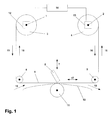
- FIG. 1 is a schematic illustration of a printer tape drive system in accordance with an embodiment of the present invention
- FIG. 2 is a schematic illustration of the controller of FIG. 1 ;
- FIG. 3 is a schematic illustration of a motor control circuit suitable for use in the tape drive of FIG. 1 .
- FIG. 1 this schematically illustrates a tape drive in accordance with the present invention suitable for use in a thermal transfer printer.
- First and second shafts 1 , 2 support a supply spool 3 and a take-up spool 4 respectively.
- the supply spool 3 is initially wound with a roll of unused tape, and the take-up spool 4 initially does not carry any tape.
- a displaceable printhead 5 is provided, displaceable relative to tape 6 in at least a first direction indicated by arrow 7 .
- Tape 6 extends from the supply spool 3 around rollers 8 , 9 to the take-up spool 4 .
- the path followed by the tape 6 between the rollers 8 and 9 passes in front of the printhead 5 .
- a substrate 10 upon which print is to be deposited is brought into contact with the tape 6 between rollers 8 and 9 , the tape 6 being interposed between the printhead 5 and the substrate 10 .
- the substrate 10 may be brought into contact with the tape 6 against a platen roller 11 .
- the supply shaft 1 is driven by a supply motor 12 and the take-up shaft 2 is driven by a take-up motor 13 .
- the supply and take-up motors 12 , 13 are illustrated in dashed outline, indicating that they are positioned behind the supply and take-up spools 3 , 4 . It will however be appreciated that in alternative embodiments of the invention, the spools are not directly driven by the motors. Instead the motor shafts may be operably connected to the respective spools by a belt drive or other similar drive mechanism.
- a controller 14 controls the operation of motors 12 , 13 as described in greater detail below.
- the supply and take-up motors 12 , 13 are capable of driving the tape 6 in both directions. Tape movement may be defined as being in the print direction if the tape is moving from the supply spool 3 to the take-up spool 4 , as indicated by arrows 15 . When tape is moving from the take-up spool 4 to the supply spool 3 , the tape may be considered to be moving in the tape reverse direction, as indicated by arrows 16 .
- the printhead 5 When the printer is operating in continuous mode the printhead 5 will be moved into contact with the tape 6 when the tape 6 is moving in the print direction 15 . Ink is transferred from the tape 6 to the substrate 10 by the action of the printhead 5 . Tape movement may be reversed such that unused portions of the tape 6 are positioned adjacent to the printhead 5 before a subsequent printing operation is commenced.
- the printer schematically illustrated in FIG. 1 can be used for both continuous and intermittent printing applications.
- the controller 14 is selectively programmable to select either continuous or intermittent operation.
- the substrate 10 will be moving continuously.
- the printhead 5 will be stationary but the tape will move so as to present fresh tape to the printhead 5 as the cycle progresses.
- intermittent applications the substrate 10 is stationary during each printing cycle, the necessary relative movement between the substrate 10 and the printhead 5 being achieved by moving the printhead 5 parallel to the tape 6 and substrate 10 in the direction of arrow 17 during the printing cycle.
- the roller 11 is replaced with a flat print platen (not shown) against which the printhead 5 presses the ribbon 6 and substrate 10 .
- both the supply motor 12 and the takeup motor 13 are position-controlled motors.
- a position-controlled motor is a motor controlled by a demanded output position. That is, the output position may be varied on demand, or the output rotational velocity may be varied by control of the speed at which the demanded output rotary position changes.
- a position-controlled motor is a stepper motor.
- a stepper motor is an example of an open loop position-controlled motor. That is, it is supplied with an input signal relating to a demanded rotational position or rotational velocity, the stepper motor being driven to achieve the demanded position or velocity.
- a stepper motor may also be provided with an encoder providing a feedback signal indicative of the actual output position or velocity. The feedback signal may be used to generate an error signal by comparison with the demanded output rotary position, the error signal being used to drive the motor to minimise the error.
- a stepper motor provided with an encoder in this manner comprises a closed loop form of position-controlled motor.
- An alternative form of closed loop position-controlled motor comprises a torque-controlled motor (e.g. a DC motor) provided with an encoder.
- a torque-controlled motor is a motor that is controlled by a demanded output torque.
- the output from the encoder provides a feedback signal from which an error signal can be generated when the feedback signal is compared to a demanded output rotary position, the error signal being used to drive the motor to minimise the error.
- DC motor is to be interpreted broadly as including any form of motor that can be driven to provide an output torque, such as a brushless DC motor, a brushed DC motor, an induction motor or an AC motor.
- a brushless DC motor comprises any form of electronically commutated motor with a commutation sensor.
- stepper motor is to be interpreted broadly as including any form of motor that can be driven by a signal indicating a required change of rotary position.
- An encoder is any form of angular position sensing device, such as an optical encoder, magnetic encoder, resolver, capacitive encoder or any other form of position sensing device.
- An encoder may be connected to an output shaft of a motor and used to provide a feedback signal indicating the angular position or motion of the motor output shaft.
- Tape is driven between the supply spool 3 and the takeup spool 4 by controlling the motors so as to maintain tension in the tape.
- tension in tape travelling between the supply spool 3 and the take-up spool 4 is monitored and the supply motor 12 and the take-up motor 13 are controlled by the controller 14 so as to maintain tape tension between predetermined limits. Suitable methods for monitoring tape tension are described in further detail below.
- the controller Operation of the controller is shown in FIG. 2 .
- Tension monitored at a first time t 1 (hereinafter “the first tension value”) is processed together with a target tension value at block 20 to generate a tension error signal ⁇ T by subtracting the first tension value from the target tension value.
- the target tension is a range of acceptable tension values, sometimes referred to as a “deadband”, in which range no tension corrections are necessary.
- the tension error signal indicates how far from the central value of this deadband the monitored tension value lies.
- the tension error signal ⁇ T is used to carry out a lookup operation in a lookup table 21 . Creation of the lookup table 21 is described in further detail below.
- the lookup table associates tension error signal values ⁇ T with corrections which should be applied to control of one of the two motors to adjust tension to correct for the processed tension error signal ⁇ T. If the motors 12 , 13 are stepper motors, for given spool diameters a number of steps through which each of the motors should be turned in normal operation is known, and the controller 14 is applied to turn the motors through the required number of steps, while tension remains between predetermined limits. However, when tension increases or decreases unacceptably, (i.e. outside the deadband) one of the motors is turned through a greater or lesser number of steps than normal, so as to correct for the tension error. This number of steps is determined from the lookup table 21 based upon the tension error signal ⁇ T.
- the lookup table 21 outputs a correction value in response to an input tension error signal, the correction value indicating a correction to be applied to one of the two motors.
- the output value is provided to motor control logic 22 which is configured to appropriately energise the motors 12 , 13 , both to move tape normally and to correct for tape tension.
- Two signals are provided to the motor control logic 22 by the lookup table 21 comprising a first signal ⁇ S s indicating a number of steps adjustment to be applied to control of the supply motor 12 and a second signal ⁇ S t indicating a number of steps adjustment to be applied to control the takeup motor 13 . It will be appreciated that one of the two values is zero in the described embodiment where a correction is required, while both values are zero while tension remains within predetermined limits.
- the lookup table is updated as tape is transported. That is, referring again to FIG. 2 , it can be seen that the first tension value input to the block 20 is also input to an update block 23 together with a second tension value measured at a second time t 2 , where the second tension value is obtained after carrying out a correction using data obtained from the lookup table 21 . The first tension value is subtracted from the second tension value to generate a tension correction value ⁇ T. The value of ⁇ T will be negative if tension has decreased and positive if tension has increased.
- the tension correction value ⁇ T obtained by applying the correction is stored in an update table 24 .
- This table stores a plurality of adjustments applied to a particular motor (each expressed as a number of steps), together with the tension correction values obtained in response to each correction, as calculated by the update block 23 .
- a plurality of tension correction values ⁇ T indicating tension corrections caused by applying the respective correction to one of the motors are stored.
- the values of ⁇ T for a particular correction i.e.
- the averaging procedure to update the lookup table 21 is only carried out if a particular correction has a predetermined minimum number of associated tension correction values.
- the update table 24 will typically only store a predetermined maximum number of tension correction values associated with a particular correction applied to one of the motors (e.g., ten).
- a tension correction value to be associated with a particular correction when applied to one of the motors can be deduced using linear interpolation or extrapolation from appropriate data in the update table 24 .
- the lookup table 21 to maintain tape tension has been described above, as has a process for updating entries of the table 21 . It will be appreciated that the table 21 must be initially calibrated. This is carried out during a calibration phase before printing operations are carried out. As a first part of the calibration phase, the spool diameters are determined. This determination can be carried out in any convenient way. For example, one known method of monitoring the diameter of a spool of tape is based upon optical sensing comprising at least one emitter and detector pair. The emitter and detector pair is arranged such that as the diameter of the spool changes, the spool blocks that signal from the emitter to the detector, which may be detected. Such an optical spool diameter monitoring technique is disclosed in our earlier UK Patent No. GB 2369602, the contents of which are herein incorporated by reference.
- GB 2298821 An alternative method for determining tape spool diameter is disclosed in GB 2298821.
- tape is passed around an idler roller of known diameter.
- the idler roller is provided with an anti-slip coating to prevent slippage occurring between the tape and the idler roller when the tape is moved.
- the outer diameter of the idler roller is known.
- Rotation of the idler roller is monitored. This is achieved by providing the idler roller with a magnetic disc having a north and south pole. Rotation of the idler roller can then be detected by an appropriate magnetic sensor. By detecting rotation of the idler roller of known diameter and knowing a number of steps through which a stepper motor has turned the diameter of a spool of tape associated with the stepper motor can be determined.
- spool diameters are required to determine steady state movement of the tape (i.e. to determine the number of steps through which the motors should be turned to move a particular linear length of tape for a printing operation).
- tape can be effectively moved from the supply spool 3 to the takeup spool 4 and vice versa.
- Operations are also carried out to obtain data used to populate the lookup table 21 . These operations involve adding or subtracting various numbers of steps from the drive signal provided to one of the motors, and recording the resulting change in tension in the tape being transported between the spools.
- This process allows a plurality of tension changes to be observed which are stored in the lookup table 21 alongside the motor control operation (e.g. addition or subtraction of a number of steps) causing the change.
- the tension error signal is used to locate a tension change having the value closest to the value of the tension error signal, and the associated motor control operation is used to adjust tape tension.
- the lookup table stores tension correction values associated with particular corrections applied to one of the motors. It will be appreciated that all possible tension correction values which may be required cannot sensibly stored in the lookup table 21 .
- the process of obtaining data from the lookup table 21 involves looking up two tension correction values having closest values to the tension error signal, obtaining corrections to be applied to the motors associated with those tension correction values and linearly interpolating the corrections to be applied to the motors to obtain accurate corrections to be applied to one of the motors.
- some entries in the lookup table 21 can be created by interpolating data obtained during the configuration phase.
- Direct tension monitoring includes, for example, a resiliently biased roller or dancing arm that is in contact with the tape, arranged such that a change in tape tension causes the roller or dancing arm to move position, the change in position being detectable using, for example a linear displacement sensor.
- tape may be passed around a roller which bears against a load cell. Tension in the tape affects the force applied to the load cell, such that the output of the load cell provides an indication of tape tension. In these cases the monitored tension is processed by the controller 14 to provide appropriate control the supply motor 12 and the take up motor 13 .
- tension can be monitored as follows. For one of the supply motor 12 and the takeup motor 13 the motor's angular velocity is measured using the provided encoder. Angular velocity is measured when the motor is moving with constant velocity.
- K r is the motor torque constant
- I is the measured current.
- ⁇ is angular velocity
- Power values for both the supply motor 12 and take-up motor 13 can be calculated using equation (2).
- the tension in the tape is then proportional to the ratio of the deduced power values.
- a measure of power may be obtained by reading a current passing through or a voltage across a resistor in series with the power supply to drive electronics associated with each of the motors.
- the ratio of power supplied to the motors can be used as a measure of the tape tension. This process is now described in further detail, together with an appropriate calibration process.
- the take-up motor 12 is energised to remove any slack from the length of ribbon extending between the two spools.
- An initial estimate of the diameters of the spools is then obtained. This initial estimate can be obtained in any convenient way. For example, an optical system such as that described in our earlier UK Patent No. GB 2,369,602 mentioned above can be used.
- the supply motor 12 is then energised in order to tension the ribbon extending around the supply spool 3 .
- the take up motor 13 is then driven so as to draw ribbon from the supply spool 3 , the supply spool motor 12 being deenergized.
- the rotational movement taken by the motor driving the take-up spool 4 is monitored.
- the other motor is not stopped, but generates a back-emf resulting in the generation of pulses that are counted.
- the rotational movement of the take-up motor 13 and the number of pulses generated by the supply motor 12 are counted and the counted numbers are used to establish the ratio between the two diameters.
- the tape is then brought to a controlled halt.
- Both motors are decelerated in a controlled manner to avoid overrun.
- the supply spool motor 12 is driven by pulses to cause deceleration.
- the application of deceleration pulses to the supply spool motor 12 in synchronism with motor rotation is achieved by monitoring the back-emf generated in that motor, and then energising the motor at an appropriate time to apply a decelerating torque.
- a number of rotations of the take up spool 4 are required to minimise the chance of any tails of ribbon extending from the spools obstructing optical paths of a scanning arrangement used to determine initial spool diameters, the arrangement being as described in our earlier UK Patent referred to above.
- a further optical scan is then performed in both directions to determine the radius of the take up spool 4 whilst that spool is stationary.
- An optical scan is then repeated as the spool is rotated in 30° increments around the motor shaft by turning the motor through an appropriate rotational movement, that appropriate movement being a constant.
- This builds up a map of the dimensions of the spool (which may not be perfectly circular) and this map is used to calculate the average radius for each spool for the arc that each will rotate in each ribbon feed and further use these radii to calculate variations in diameter around the spool axes. This makes it possible to accurately determine the circumference of each spool and the effect of a predetermined rotational movement of the motor driving that spool.
- the different calculated radii can be used to calculate the rotational movement required by each motor to drive the spools in an appropriate manner so as to feed the ribbon a predetermined distance. These radii and rotational movements may then be used in tension monitoring calculations such as those described below.
- Stepper motors generally comprise two quadrature-wound coils and current is supplied in a sequence of pulses to one or both of the coils and in both senses (positive and negative) so as to achieve step advance of the motor shafts.
- over-drive stepper motors by applying a voltage that is much larger than the nominal rating of the motor and to pulse width modulate this voltage when the desired motor current is reached. For example, with a 3.6 volt motor capable of taking say 2 amps, a voltage of 36 volts may be applied. This results in a very rapid rise in current through the motor, typically in a few tens of micro seconds.
- x is the calibration factor for the motor at the given speed
- V is the average measured motor operation value at the given speed
- N is a constant normalisation or scaling factor.
- a series of values x is calculated for each of the predetermined speeds.
- one of the values x is selected for use in the calculation of ribbon tension, or a value for x is calculated for the given speed by interpolation from the two values of x for the predetermined speed closest to the given speed.
- FIG. 3 illustrates the calculation of the values V both during motor calibration and in subsequent ribbon tension control.
- a regulated power supply 30 energises a first motor drive circuit 31 and a second motor drive circuit 32 .
- Current from the supply 30 to the motor drive circuit 31 is delivered through a low resistance resistor 33 , the potential developed across the resistor 33 being applied to a level translator 34 .
- current to the motor drive 32 is delivered through a low resistance value resistor 35 and the voltage developed across that resistor is applied to a level translator 36 .
- the outputs of the level translators 34 and 36 are applied to analogue to digital converters 37 and 38 the outputs of which are applied to a micro controller 39 .
- the micro controller delivers an output 40 to the first motor drive 31 and an output 41 to the second motor drive 32 .
- the motor drives energise the supply motor 12 driving the supply spool 3 and the take-up motor 13 driving the take-up spool 4 .
- V 1 is the output of ADC 28 given a selected constant step-rate ribbon feed
- V 2 is the output of ADC 27 during ribbon feed
- r 1 is the radius of the spool 34 ;
- r 2 is the radius of the spool 35 ;
- x 2 is the calibration factor for motor 33 for the speed of motor 33 ;
- T is the ribbon tension
- f(Temp) is a temperature-related function.
- tension is monitored using an alternative method.
- the spools may be held by a known current.
- current is proportionally related to torque by the motor's torque constant, the torque provided by each motor can be determined.
- Tension can then be calculated by dividing the torque value by the radius of each spool. Given that each value should ideally be equal, the obtained values can be averaged to improve accuracy.
- A is the acceleration per unit of current
- K t is the torque constant of the motor
- A′ is the measured acceleration
- I J is the current producing that acceleration.
- t is tape tension
- R is spool radius
- a particularly low tension reading is calculated by any of the above methods, this can be taken by the control system as indicating a fault condition, for example ribbon breakage, or the ribbon becoming so slack that the system is most unlikely to be able to effect adequate control.
- the control system can output a “broken ribbon” predetermined low limits, such that when the measured tension falls below this limit, the control system can halt the printing process and assert appropriate fault outputs and warning messages.
- the system can offer valuable “broken ribbon” detection without the need for additional sensing arrangements.
- references are made to computing an average in the preceding description, such references should be construed as references to any appropriate computation producing a value from a plurality of values.
- conventional “averaging” operations such as computation of a mean, median or mode value are contemplated, so are other techniques such as, for example various computations applying appropriate weightings to the values.
Abstract
Description
T=K t I (1)
where:
P=Tω (2)
where:
x=N/V
where:
V I x 1=(N+r 1 Tx 1)f(Temp) (3)
V 2 x 2=(N−r 2 Tx 2)f(Temp) (4)
where:
t=N((V 1 /x 2)−(V 2 /x 1))/(V 2 r 1 +V 1 r 2) (5)
Thus for any given speed for the motors, the appropriate calibration factors x1, x2 can be looked up and used to derive a measure of the ribbon tension t.
A=K t /J (6)
where:
A′=A/I J (7)
where:
I m =I J +I T (8)
where Im is the current provided to the motor; and
IT is the current providing tension in the tape which can be calculated from a knowledge of ribbon density and spool diameter.
I m −A′/(K t /J)=I T (9)
t=(I T K T)/R (10)
where:
Claims (16)
Priority Applications (1)
| Application Number | Priority Date | Filing Date | Title |
|---|---|---|---|
| US12/058,829 US8317421B2 (en) | 2007-03-31 | 2008-03-31 | Tape drive tension control |
Applications Claiming Priority (4)
| Application Number | Priority Date | Filing Date | Title |
|---|---|---|---|
| GB0706358A GB2449053B (en) | 2007-03-31 | 2007-03-31 | Tape drive |
| GB0706358.9 | 2007-03-31 | ||
| US90974207P | 2007-04-03 | 2007-04-03 | |
| US12/058,829 US8317421B2 (en) | 2007-03-31 | 2008-03-31 | Tape drive tension control |
Publications (2)
| Publication Number | Publication Date |
|---|---|
| US20080240830A1 US20080240830A1 (en) | 2008-10-02 |
| US8317421B2 true US8317421B2 (en) | 2012-11-27 |
Family
ID=39539515
Family Applications (1)
| Application Number | Title | Priority Date | Filing Date |
|---|---|---|---|
| US12/058,829 Active 2031-06-28 US8317421B2 (en) | 2007-03-31 | 2008-03-31 | Tape drive tension control |
Country Status (3)
| Country | Link |
|---|---|
| US (1) | US8317421B2 (en) |
| EP (1) | EP2134549B1 (en) |
| WO (1) | WO2008119927A1 (en) |
Cited By (9)
| Publication number | Priority date | Publication date | Assignee | Title |
|---|---|---|---|---|
| US20130106974A1 (en) * | 2000-09-11 | 2013-05-02 | Videojet Technologies (Nottingham) Limited | Tape drive and printing apparatus |
| US20130182059A1 (en) * | 2012-01-16 | 2013-07-18 | Shuhei TERAUCHI | Thermal transfer printer |
| US20130215210A1 (en) * | 2011-08-15 | 2013-08-22 | Martin McNestry | Thermal transfer printer |
| US20140132698A1 (en) * | 2012-11-09 | 2014-05-15 | Markem-Imaje Limited | Tape Drive and Method of Operation of a Tape Drive |
| US20140225969A1 (en) * | 2013-02-12 | 2014-08-14 | Phillip Lakin | Tape Drive and Method of Operation |
| US9145000B2 (en) | 2013-02-13 | 2015-09-29 | Dover Europe Sàrl | Printing apparatus and method of operating a printing apparatus |
| US9272531B2 (en) | 2013-02-13 | 2016-03-01 | Dover Europe Sarl | Tape drive and method of operation of a tape drive |
| US9340052B2 (en) | 2011-08-10 | 2016-05-17 | Markem-Imaje Industries Limited | Motor control system |
| US10347282B2 (en) | 2017-06-23 | 2019-07-09 | International Business Machines Corporation | Tape transport control with suppression of time-varying tension disturbances |
Families Citing this family (7)
| Publication number | Priority date | Publication date | Assignee | Title |
|---|---|---|---|---|
| FR2940551B1 (en) * | 2008-12-23 | 2010-12-17 | Thales Sa | CONTROL SYSTEM FOR DIRECT CURRENT MOTOR ACTUATOR WITH RIGHT NOTCHES |
| GB2482167B (en) * | 2010-07-22 | 2016-06-08 | Markem-Imaje Ind Ltd | Tape drive and method of operation of a tape drive |
| JP6346775B2 (en) * | 2014-04-08 | 2018-06-20 | キヤノンファインテックニスカ株式会社 | Printing device |
| US9688086B2 (en) * | 2014-04-08 | 2017-06-27 | Nisca Corporation | Printing apparatus |
| JP6931300B2 (en) * | 2017-06-22 | 2021-09-01 | 東芝テック株式会社 | Printers and programs |
| NL2019160B1 (en) * | 2017-07-03 | 2019-01-14 | B V Korthofah | Thermal transfer printer |
| DE102020121012A1 (en) | 2020-08-10 | 2022-02-10 | Mobil-Mark Gmbh | Attachment for a device head of a laser marking device |
Citations (164)
| Publication number | Priority date | Publication date | Assignee | Title |
|---|---|---|---|---|
| US3584805A (en) | 1969-03-24 | 1971-06-15 | Recortec Inc | Tape transport apparatus |
| US3606201A (en) | 1969-07-15 | 1971-09-20 | Sperry Rand Corp | Constant speed,constant tension tape transport |
| US3610496A (en) | 1967-12-06 | 1971-10-05 | Carroll H Parker | Automatic tension controller |
| US3704401A (en) | 1970-07-20 | 1972-11-28 | Intern Computer Products Inc | Dual motor control |
| US3781490A (en) | 1973-06-01 | 1973-12-25 | Ibm | Web tension and speed control in a reel-to-reel web transport |
| GB1361288A (en) | 1972-09-06 | 1974-07-24 | Honeywell Ltd | Spooling apparatus for strip material |
| US3836831A (en) | 1971-09-25 | 1974-09-17 | Philips Corp | Plural motor tension controlled tape drive |
| US3863117A (en) | 1973-04-09 | 1975-01-28 | Electronic Associates | Plural motor tensioning system for rewinding tape cassettes |
| US3889893A (en) | 1974-01-14 | 1975-06-17 | Computer Peripherals | Ribbon drive and control system |
| US3902585A (en) | 1973-05-07 | 1975-09-02 | Data Products Corp | Electric switch actuated printer ribbon reversing mechanism |
| US3910527A (en) | 1974-03-08 | 1975-10-07 | Ibm | Web distribution controlled servomechanism in a reel-to-reel web transport |
| US3982160A (en) | 1974-03-14 | 1976-09-21 | Rca Corporation | System for controlling tension of magnetic tape |
| US3984809A (en) | 1975-11-20 | 1976-10-05 | Michael L. Dertouzos | Parallel thermal printer |
| US4000804A (en) | 1975-02-10 | 1977-01-04 | Ing. C. Olivetti & C., S.P.A. | Arrangement for transferring a ribbon from a feed spool to a take-up spool |
| US4012674A (en) | 1975-04-07 | 1977-03-15 | Computer Peripherals, Inc. | Dual motor web material transport system |
| US4015799A (en) | 1975-11-14 | 1977-04-05 | International Business Machines Corporation | Adaptive reel-to-reel tape control system |
| US4025830A (en) | 1975-02-03 | 1977-05-24 | Computer Peripherals, Inc. | Motor control and web material drive system |
| US4079828A (en) | 1976-08-24 | 1978-03-21 | Teletype Corporation | Apparatus for controlling the bi-directional transport of a flexible web |
| US4091913A (en) | 1976-12-06 | 1978-05-30 | Xerox Corporation | Printing apparatus with printing material non-motion detector |
| US4093149A (en) | 1975-11-28 | 1978-06-06 | Honeywell Inc. | Cartridge tape recorder system and cartridge therefor |
| US4094478A (en) | 1975-11-28 | 1978-06-13 | Honeywell Inc. | Dual motor tape recorder system |
| US4096417A (en) | 1975-11-03 | 1978-06-20 | Compagnie Internationale Pour L'informatique Cii-Honeywell Bull (Societe Anonyme) | Apparatus for driving and tensioning a printing ribbon for a printer |
| US4095758A (en) | 1975-11-28 | 1978-06-20 | Honeywell Inc. | Tape recorder system |
| US4156257A (en) | 1975-12-22 | 1979-05-22 | Mfe Corporation | Motor control circuit for tape drive unit |
| US4161001A (en) | 1976-07-05 | 1979-07-10 | Sony Corporation | Video signal reproducing apparatus with a manually controlled track searching arrangement |
| US4177731A (en) | 1976-07-26 | 1979-12-11 | Printronix, Inc. | Printer system ribbon drive having constant ribbon speed and tension |
| GB1576750A (en) | 1976-07-26 | 1980-10-15 | Printronix Inc | Printer system ribbon drive having constant ribbon speed and tension |
| USRE30448E (en) | 1975-11-28 | 1980-12-16 | Honeywell Inc. | Tape recorder system |
| US4256996A (en) * | 1979-01-29 | 1981-03-17 | Spin Physics, Inc. | Web transport system |
| US4266479A (en) | 1977-12-12 | 1981-05-12 | Sperry Corporation | Multi-function mechanical printer drive means |
| US4286888A (en) | 1978-12-28 | 1981-09-01 | Centronics Data Computer Corp. | Bi-directional belt drive, print head mounting means and printing plane adjustment means for serial printers |
| US4294552A (en) | 1980-01-28 | 1981-10-13 | International Business Machines Corporation | Bidirectional ribbon drive control for printers |
| US4313376A (en) | 1980-03-11 | 1982-02-02 | Rennco Incorporated | Imprinter |
| US4313683A (en) | 1979-10-19 | 1982-02-02 | International Business Machines Corporation | Microcomputer control of ribbon drive for printers |
| US4354211A (en) | 1980-05-19 | 1982-10-12 | Microcomputer Systems Corporation | Magnetic tape apparatus |
| US4366371A (en) | 1977-12-09 | 1982-12-28 | Alayer De Costemore D Arc Step | Method and apparatus for controlling tape transport apparatus for cassettes |
| US4375339A (en) | 1980-12-01 | 1983-03-01 | International Business Machines Corporation | Electrically conductive ribbon break detector for printers |
| US4398227A (en) * | 1981-03-16 | 1983-08-09 | Storage Technology Corporation | Magnetic tape drive with adaptive servo |
| US4400745A (en) * | 1980-11-17 | 1983-08-23 | Del Mar Avionics | Tape transport |
| US4448368A (en) | 1982-03-23 | 1984-05-15 | Raymond Engineering Inc. | Control for tape drive system |
| US4461433A (en) * | 1981-04-14 | 1984-07-24 | Sony Corporation | Tape speed control apparatus |
| GB2087104B (en) | 1980-10-30 | 1984-10-10 | Ampex | Digital open loop tape tension control circuit |
| US4479081A (en) | 1983-05-13 | 1984-10-23 | General Electric Company | Step motor drive |
| GB2077970B (en) | 1980-02-26 | 1984-12-19 | Teraoka Seikosho Kk | A label printer |
| US4525654A (en) * | 1981-12-09 | 1985-06-25 | Hitachi, Ltd. | Tape transport control unit |
| US4573645A (en) | 1983-11-23 | 1986-03-04 | Genicom Corporation | Ribbon tension control |
| GB2163915A (en) | 1984-08-28 | 1986-03-05 | Hewlett Packard Co | Web drive apparatus |
| US4577198A (en) | 1983-08-24 | 1986-03-18 | Alps Electric Company, Ltd. | Thermal transfer printer |
| US4589603A (en) | 1983-01-21 | 1986-05-20 | Grapha-Holding Ag | Apparatus for temporary storage of a stream of partially overlapping sheets |
| US4632582A (en) | 1985-02-22 | 1986-12-30 | Centronics Data Computer Corp. | Ribbon feed mechanism providing a constant relative velocity between ribbon and print head |
| US4639880A (en) | 1984-08-21 | 1987-01-27 | Brother Industries, Ltd. | Ribbon feed system of combined printer |
| US4642655A (en) | 1986-04-14 | 1987-02-10 | Eastman Kodak Company | Color-indexed dye frames in thermal printers |
| US4650350A (en) | 1984-02-23 | 1987-03-17 | Kunz Ag | Method and apparatus for thermal printing of plastic cards |
| US4664336A (en) | 1984-05-31 | 1987-05-12 | Fujitsu Limited | Motor control apparatus for reel-to-reel tape drive system |
| US4696439A (en) | 1985-04-12 | 1987-09-29 | Teac Corporation | Tape speed and tension control system for a magnetic tape cassette apparatus |
| US4712113A (en) | 1986-07-17 | 1987-12-08 | Ncr Canada Ltd - Ncr Canada Ltee | Thermal transfer ribbon mechanism and recording method |
| US4752842A (en) | 1984-01-25 | 1988-06-21 | Sony Corporation | Tape driving system for a magnetic transfer apparatus |
| US4760405A (en) | 1985-10-22 | 1988-07-26 | Canon Kabushiki Kaisha | Method and apparatus for recording an image |
| US4786992A (en) | 1985-10-11 | 1988-11-22 | Hitachi, Ltd. | Apparatus and method for controlling tape tension using acceleration and average tension deviation information to adjust motor drive currents |
| US4788558A (en) | 1987-02-06 | 1988-11-29 | Intermec Corporation | Method and apparatus for controlling tension in tape progressed along a feed path |
| EP0157096B1 (en) | 1984-01-28 | 1989-05-24 | Kabushiki Kaisha Sato | Winding mechanism for tape-like web |
| EP0329478A2 (en) | 1988-02-18 | 1989-08-23 | Kabushiki Kaisha Toshiba | Thermal recording printer |
| US4895466A (en) | 1988-01-20 | 1990-01-23 | Datamax Corporation | Processor for forms with multi-format data |
| US4897668A (en) | 1987-03-02 | 1990-01-30 | Kabushiki Kaisha Toshiba | Apparatus for transferring ink from ink ribbon to a recording medium by applying heat to the medium, thereby recording data on the medium |
| EP0176009B1 (en) | 1984-09-12 | 1990-03-07 | Kabushiki Kaisha Sato | Carbon ribbon transport guide device |
| US4909648A (en) | 1988-01-20 | 1990-03-20 | Datamax Corporation | Processor for forms with multi-format data |
| GB2175253B (en) | 1985-05-10 | 1990-03-21 | Toshiba Kk | Thermal-transfer printer |
| US4924240A (en) | 1987-11-02 | 1990-05-08 | Alcatel Business Systems, Limited | Feed for thermal printing ribbon |
| US4952085A (en) | 1988-03-03 | 1990-08-28 | Alcatel N.V. | Printer for generating images with high contrast gray and color tone gradations |
| US4953044A (en) | 1988-10-28 | 1990-08-28 | Storage Technology Corporation | Closed loop tape thread/unthread apparatus |
| US4977466A (en) | 1988-07-04 | 1990-12-11 | Fuji Photo Film Co., Ltd. | Magnetic tape wind-up control method, and tape wind-up apparatus |
| US5012989A (en) | 1989-11-24 | 1991-05-07 | Eastman Kodak Company | Apparatus and method for tape velocity and tension control in a capstanless magnetic tape transport |
| US5017943A (en) | 1987-12-09 | 1991-05-21 | Shinko Electric Co., Ltd. | Thermal transfer type color printer |
| US5039027A (en) * | 1988-11-04 | 1991-08-13 | Hitachi, Ltd. | Method for control of tape tension between the reels and apparatus therefor |
| US5080296A (en) | 1990-09-24 | 1992-01-14 | General Atomics | Low tension wire transfer system |
| EP0481579A2 (en) | 1990-10-19 | 1992-04-22 | MANNESMANN Aktiengesellschaft | Magnetic readable character printing process using matrix print heads and method for making the same |
| US5121136A (en) | 1990-03-20 | 1992-06-09 | Ricoh Company, Ltd. | Recorder for thermal transfer recording operations |
| US5125592A (en) | 1989-12-18 | 1992-06-30 | Sony Corporation | Tape transport system with servo gain responsive to detected tape tension |
| US5160943A (en) | 1988-08-12 | 1992-11-03 | Esselte Meto International Produktions Gmbh | Printing systems |
| US5162815A (en) | 1990-06-25 | 1992-11-10 | Eastman Kodak Company | Thermal printing apparatus with tensionless donor web during printing |
| US5218490A (en) | 1989-04-25 | 1993-06-08 | Sony Corporation | Tape tension servo-system for video tape recording and/or reproducing apparatus |
| US5222684A (en) * | 1990-03-19 | 1993-06-29 | Matsushita Electric Industrial Co., Ltd. | Tape driving apparatus for tape medium record reproducing apparatus |
| EP0294633B1 (en) | 1987-06-09 | 1993-10-13 | Kabushiki Kaisha Sato | Carbon ribbon supply apparatus for a printer |
| US5259563A (en) | 1989-11-13 | 1993-11-09 | Sharp Kabushiki Kaisha | Magnetic recording/reproducing apparatus without capstan |
| DE4215830A1 (en) | 1992-05-15 | 1993-11-18 | Thomson Brandt Gmbh | Regulating speed and/or position of electromotor(s) - using sensor to feed back speed and position information for comparison and to generate regulating signal |
| US5281038A (en) | 1990-02-21 | 1994-01-25 | Datacard Corporation, Inc. | Apparatus and method for printing including a ribbon advancing slide mechanism |
| US5295753A (en) | 1990-05-17 | 1994-03-22 | Seiko Epson Corporation | Label tape printing system using thermal head and transfer ink ribbon |
| US5297879A (en) | 1992-04-27 | 1994-03-29 | Kabushiki Kaisha Sato | Mechanism for preventing slack in printer carbon ribbon |
| US5300953A (en) | 1992-09-24 | 1994-04-05 | Pitney Bowes Inc. | Thermal ribbon cassette tension control for a thermal postage meter |
| US5313343A (en) | 1990-06-28 | 1994-05-17 | Canon Kabushiki Kaisha | Magnetic recording or reproducing apparatus |
| US5330118A (en) * | 1990-11-27 | 1994-07-19 | Matsushita Electric Industrial Co., Ltd. | Tape driving apparatus |
| US5357270A (en) | 1989-12-22 | 1994-10-18 | Neopost Limited | Thermal transfer printing |
| US5366303A (en) | 1991-12-13 | 1994-11-22 | Printronix, Inc. | Printer ribbon motor controller |
| US5372439A (en) | 1992-12-18 | 1994-12-13 | Zebra Technologies Corporation | Thermal transfer printer with controlled ribbon feed |
| EP0556066B1 (en) | 1992-02-13 | 1995-05-03 | ITW Limited | Print head movement control |
| US5477400A (en) | 1992-08-06 | 1995-12-19 | Canon Kabushiki Kaisha | Tape transport system control device |
| US5490638A (en) | 1992-02-27 | 1996-02-13 | International Business Machines Corporation | Ribbon tension control with dynamic braking and variable current sink |
| US5505550A (en) | 1994-03-23 | 1996-04-09 | Kabushiki Kaisha Tec | Printer and method of supplying continuous paper to printing portion |
| GB2289441B (en) | 1994-05-20 | 1996-04-24 | Prestek Ltd | Method of printing |
| US5529410A (en) * | 1994-10-28 | 1996-06-25 | Pitney Bowes Inc. | Method and apparatus for controlling tension on a sheet material in a reel-to-reel transport system |
| GB2272669B (en) | 1992-11-20 | 1996-09-25 | Neopost Ltd | Printing apparatus |
| EP0734876A2 (en) | 1995-03-31 | 1996-10-02 | ITW Limited | A printer for printing on a continuous print medium |
| EP0741044A2 (en) | 1993-11-05 | 1996-11-06 | Esselte N.V. | Drive system for a printing apparatus |
| US5576751A (en) | 1990-02-01 | 1996-11-19 | Canon Kabushiki Kaisha | Apparatus for either continuous or intermittent thermal transfer recording |
| US5604652A (en) | 1991-09-10 | 1997-02-18 | Matsushita Electric Industrial Co., Ltd. | Tape speed control apparatus using rotation speed ratio of first and second tape reels |
| US5609425A (en) | 1994-02-28 | 1997-03-11 | Shinko Electric Co., Ltd. | Thermal sublimation printer for use with different ribbons |
| EP0589715B1 (en) | 1992-09-24 | 1997-03-12 | Pitney Bowes Inc. | Thermal ribbon cassette tension control for a thermal printing postage meter |
| US5639040A (en) | 1993-07-21 | 1997-06-17 | Sony Corporation | Apparatus for detectng abnormality of a tape-tension detecting means of a magnetic recording apparatus |
| US5647679A (en) | 1996-04-01 | 1997-07-15 | Itw Limited | Printer for printing on a continuous print medium |
| US5649672A (en) | 1994-06-15 | 1997-07-22 | Imation Corp. | Motor control of tape tension in a belt cartridge |
| US5649774A (en) | 1994-05-26 | 1997-07-22 | Illinois Tool Works Inc. | Method and apparatus for improved low cost thermal printing |
| US5700096A (en) | 1993-01-29 | 1997-12-23 | Tohoku Ricoh Co., Ltd. | Printer and method of printing using the same |
| US5701214A (en) | 1991-06-03 | 1997-12-23 | Hitachi, Ltd. | Tape loading device in magnetic recording/playback apparatus that controls loading based on calculated reel inertia and tape position |
| US5720442A (en) | 1995-07-19 | 1998-02-24 | Hitachi, Ltd. | Capstanless tape driving method and information recording and reproduction apparatus |
| US5731672A (en) | 1994-07-29 | 1998-03-24 | Fujitsu Limited | Control apparatus of DC servo motor |
| GB2302523B (en) | 1995-04-12 | 1998-03-25 | Prestek Ltd | Method of printing |
| EP0840311A1 (en) | 1996-10-31 | 1998-05-06 | Ampex Corporation | Hybrid arm-position/tape-tension servo control system |
| EP0842785A1 (en) | 1996-10-15 | 1998-05-20 | ITW Limited | A method of operating a thermal printer |
| EP0854480A1 (en) | 1997-01-17 | 1998-07-22 | Tandberg Data ASA | Tape drive speed and tension control |
| US5788384A (en) | 1996-05-10 | 1998-08-04 | Monarch Marking Systems, Inc. | Printer with ink ribbon spool electric motors |
| GB2310405B (en) | 1995-03-15 | 1998-08-05 | Markem Tech Ltd | Method of calibrating a ribbon winding mechanism for a printing apparatus |
| US5803624A (en) | 1995-08-31 | 1998-09-08 | Intermec Corporation | Methods and apparatus for compensatng step distance in a stepping motor driven label printer |
| US5816719A (en) | 1997-02-26 | 1998-10-06 | Itw Limited | Printer for printing on a continuous print medium |
| US5820280A (en) | 1997-08-28 | 1998-10-13 | Intermec Corporation | Printer with variable torque distribution |
| US5906444A (en) | 1998-01-16 | 1999-05-25 | Illinois Tool Works Inc. | Bi-directional thermal printer and method therefor |
| EP0936078A2 (en) | 1998-02-13 | 1999-08-18 | Allen Coding Systems Limited | Printing apparatus |
| GB2315244B (en) | 1996-03-29 | 1999-09-15 | Markem Tech Ltd | Method of printing |
| EP0955178A2 (en) | 1998-05-05 | 1999-11-10 | Printronix, Inc. | Print ribbon feeder and detection system |
| GB2306916B (en) | 1995-11-13 | 1999-11-17 | Prestek Ltd | Printing apparatus and method of printing |
| US5993092A (en) | 1997-02-26 | 1999-11-30 | Itw Limited | Printer with reversible ribbon driving means for rewinding overshot ribbon |
| US6000868A (en) | 1994-09-01 | 1999-12-14 | Sharp Kabushiki Kaisha | Printer system with automatic ink ribbon cassette exchange function |
| US6036382A (en) | 1997-08-16 | 2000-03-14 | Willett International Limited | Ribbon transport mechanism having driven pivoting carrier beam and method of using |
| FR2783459A1 (en) | 1998-09-21 | 2000-03-24 | Polyprint | Thermal printer ribbon tensioner mechanism having paper feed with ink ribbon passing roller/print mechanism and ribbon tension measurement/ control. |
| US6046756A (en) | 1995-09-29 | 2000-04-04 | Toshiba Tec Kabushiki Kaisha | Printer device |
| EP0683055B1 (en) | 1994-05-20 | 2000-05-24 | Markem Technologies Limited | Economic use of impression transfer material printing method |
| US6082914A (en) | 1999-05-27 | 2000-07-04 | Printronix, Inc. | Thermal printer and drive system for controlling print ribbon velocity and tension |
| US6128152A (en) | 1992-12-22 | 2000-10-03 | Deutsche Thomson-Brandt Gmbh | Method and apparatus for regulating the speed of a tape |
| US6142686A (en) | 1998-03-02 | 2000-11-07 | Brady Worldwide | Method and apparatus for maintaining ribbon tension |
| GB2349605A (en) | 1999-05-05 | 2000-11-08 | Allen Coding Systems Ltd | Thermal tape transfer mechanism wherein the tape is driven in a reverse direction following a print action for reuse thereof |
| US6164203A (en) | 1996-05-10 | 2000-12-26 | Monarch Marking Systems, Inc. | Printer |
| GB2354974A (en) | 1999-10-05 | 2001-04-11 | Allen Coding Systems Ltd | Print head temperature control system for a thermal contact printer which prints product codes onto a moving substrate via a foil |
| US6261012B1 (en) | 1999-05-10 | 2001-07-17 | Fargo Electronics, Inc. | Printer having an intermediate transfer film |
| US6305629B1 (en) | 2000-05-12 | 2001-10-23 | International Business Machines Corporation | Servo error detection of bi-directional reel-to-reel tape drives using fine line tachometers |
| US6305628B1 (en) | 1998-11-18 | 2001-10-23 | Seagate Removable Storage Solutions Llc | Controlled tape stopping with feed forward during power loss |
| US6307583B1 (en) | 1999-09-01 | 2001-10-23 | Illinois Tool Works Inc. | Thermal printer with reversible ribbon and method therefor |
| US6315471B1 (en) | 1999-08-21 | 2001-11-13 | Industrial Technology Research Institute | Apparatus for controlling ribbon tension in a thermal printer |
| EP0830252B1 (en) | 1996-03-29 | 2002-01-02 | Markem Technologies Limited | Method of printing |
| GB2369326B (en) | 2000-09-11 | 2002-10-09 | Zipher Ltd | Versatile printer |
| GB2343655B (en) | 1998-11-13 | 2002-12-24 | Markem Tech Ltd | Method of printing |
| US20030049065A1 (en) | 1999-05-27 | 2003-03-13 | Barrus Gordon B. | Thermal printer with impoved transport, drive, and remote controls |
| US6669136B2 (en) | 2000-12-22 | 2003-12-30 | Hitachi, Ltd. | Paper money handling device |
| US20040041047A1 (en) | 2002-09-04 | 2004-03-04 | International Business Machines Corporation | Combined tension control for tape |
| US6754026B1 (en) | 1999-10-28 | 2004-06-22 | International Business Machines Corporation | Tape transport servo system and method for a computer tape drive |
| EP0945273B1 (en) | 1998-03-26 | 2004-07-07 | Markem Technologies Limited | Method of printing |
| GB2376662B (en) | 2001-06-20 | 2004-10-20 | Markem Tech Ltd | Improvements in or relating to printing apparatus |
| GB2404703A (en) | 2003-08-01 | 2005-02-09 | Markem Tech Ltd | Slipping clutch with ceramic coating on bearing surface |
| GB2404896A (en) | 2003-08-14 | 2005-02-16 | Markem Tech Ltd | Ribbon transport mechanism having tensioning means |
| US6969064B2 (en) | 2003-06-03 | 2005-11-29 | Hitachi, Ltd. | Paper sheet storing and releasing apparatus |
| EP1409388B1 (en) | 2001-07-20 | 2006-01-18 | Wincor Nixdorf International GmbH | Method for controlling a web accumulator and web accumulator for storing sheetlike objects |
| GB2416237A (en) | 2004-07-12 | 2006-01-18 | Markem Tech Ltd | Method of printing |
| GB2400818B (en) | 2003-04-22 | 2006-02-08 | Markem Tech Ltd | Apparatus for controlling a ribbon transport mechanism |
| GB2422815A (en) | 2005-02-08 | 2006-08-09 | Markem Tech Ltd | Laminae handling apparatus |
| EP1470926B1 (en) | 2003-04-22 | 2007-03-28 | Markem Technologies Limited | Apparatus for controlling a ribbon transport mechanism |
| EP1400362B1 (en) | 2002-08-14 | 2011-04-27 | Printronix, Inc. | Printer and print correlation method |
Family Cites Families (1)
| Publication number | Priority date | Publication date | Assignee | Title |
|---|---|---|---|---|
| GB0123303D0 (en) * | 2001-09-28 | 2001-11-21 | Zipher Ltd | Tape drive |
-
2008
- 2008-02-29 EP EP08709558.4A patent/EP2134549B1/en active Active
- 2008-02-29 WO PCT/GB2008/000684 patent/WO2008119927A1/en active Application Filing
- 2008-03-31 US US12/058,829 patent/US8317421B2/en active Active
Patent Citations (181)
| Publication number | Priority date | Publication date | Assignee | Title |
|---|---|---|---|---|
| US3610496A (en) | 1967-12-06 | 1971-10-05 | Carroll H Parker | Automatic tension controller |
| US3584805A (en) | 1969-03-24 | 1971-06-15 | Recortec Inc | Tape transport apparatus |
| US3606201A (en) | 1969-07-15 | 1971-09-20 | Sperry Rand Corp | Constant speed,constant tension tape transport |
| US3704401A (en) | 1970-07-20 | 1972-11-28 | Intern Computer Products Inc | Dual motor control |
| US3836831A (en) | 1971-09-25 | 1974-09-17 | Philips Corp | Plural motor tension controlled tape drive |
| GB1361288A (en) | 1972-09-06 | 1974-07-24 | Honeywell Ltd | Spooling apparatus for strip material |
| US3863117A (en) | 1973-04-09 | 1975-01-28 | Electronic Associates | Plural motor tensioning system for rewinding tape cassettes |
| US3902585A (en) | 1973-05-07 | 1975-09-02 | Data Products Corp | Electric switch actuated printer ribbon reversing mechanism |
| US3781490A (en) | 1973-06-01 | 1973-12-25 | Ibm | Web tension and speed control in a reel-to-reel web transport |
| US3889893A (en) | 1974-01-14 | 1975-06-17 | Computer Peripherals | Ribbon drive and control system |
| US3910527A (en) | 1974-03-08 | 1975-10-07 | Ibm | Web distribution controlled servomechanism in a reel-to-reel web transport |
| US3982160A (en) | 1974-03-14 | 1976-09-21 | Rca Corporation | System for controlling tension of magnetic tape |
| US4025830A (en) | 1975-02-03 | 1977-05-24 | Computer Peripherals, Inc. | Motor control and web material drive system |
| US4000804A (en) | 1975-02-10 | 1977-01-04 | Ing. C. Olivetti & C., S.P.A. | Arrangement for transferring a ribbon from a feed spool to a take-up spool |
| US4012674A (en) | 1975-04-07 | 1977-03-15 | Computer Peripherals, Inc. | Dual motor web material transport system |
| US4096417A (en) | 1975-11-03 | 1978-06-20 | Compagnie Internationale Pour L'informatique Cii-Honeywell Bull (Societe Anonyme) | Apparatus for driving and tensioning a printing ribbon for a printer |
| US4015799A (en) | 1975-11-14 | 1977-04-05 | International Business Machines Corporation | Adaptive reel-to-reel tape control system |
| US3984809A (en) | 1975-11-20 | 1976-10-05 | Michael L. Dertouzos | Parallel thermal printer |
| US4094478A (en) | 1975-11-28 | 1978-06-13 | Honeywell Inc. | Dual motor tape recorder system |
| US4093149A (en) | 1975-11-28 | 1978-06-06 | Honeywell Inc. | Cartridge tape recorder system and cartridge therefor |
| US4095758A (en) | 1975-11-28 | 1978-06-20 | Honeywell Inc. | Tape recorder system |
| USRE30448E (en) | 1975-11-28 | 1980-12-16 | Honeywell Inc. | Tape recorder system |
| US4156257A (en) | 1975-12-22 | 1979-05-22 | Mfe Corporation | Motor control circuit for tape drive unit |
| US4161001A (en) | 1976-07-05 | 1979-07-10 | Sony Corporation | Video signal reproducing apparatus with a manually controlled track searching arrangement |
| US4177731A (en) | 1976-07-26 | 1979-12-11 | Printronix, Inc. | Printer system ribbon drive having constant ribbon speed and tension |
| GB1576750A (en) | 1976-07-26 | 1980-10-15 | Printronix Inc | Printer system ribbon drive having constant ribbon speed and tension |
| US4079828A (en) | 1976-08-24 | 1978-03-21 | Teletype Corporation | Apparatus for controlling the bi-directional transport of a flexible web |
| US4091913A (en) | 1976-12-06 | 1978-05-30 | Xerox Corporation | Printing apparatus with printing material non-motion detector |
| US4366371A (en) | 1977-12-09 | 1982-12-28 | Alayer De Costemore D Arc Step | Method and apparatus for controlling tape transport apparatus for cassettes |
| US4266479A (en) | 1977-12-12 | 1981-05-12 | Sperry Corporation | Multi-function mechanical printer drive means |
| US4286888A (en) | 1978-12-28 | 1981-09-01 | Centronics Data Computer Corp. | Bi-directional belt drive, print head mounting means and printing plane adjustment means for serial printers |
| US4256996A (en) * | 1979-01-29 | 1981-03-17 | Spin Physics, Inc. | Web transport system |
| US4313683A (en) | 1979-10-19 | 1982-02-02 | International Business Machines Corporation | Microcomputer control of ribbon drive for printers |
| US4294552A (en) | 1980-01-28 | 1981-10-13 | International Business Machines Corporation | Bidirectional ribbon drive control for printers |
| GB2077970B (en) | 1980-02-26 | 1984-12-19 | Teraoka Seikosho Kk | A label printer |
| US4313376A (en) | 1980-03-11 | 1982-02-02 | Rennco Incorporated | Imprinter |
| US4354211A (en) | 1980-05-19 | 1982-10-12 | Microcomputer Systems Corporation | Magnetic tape apparatus |
| GB2087104B (en) | 1980-10-30 | 1984-10-10 | Ampex | Digital open loop tape tension control circuit |
| US4400745A (en) * | 1980-11-17 | 1983-08-23 | Del Mar Avionics | Tape transport |
| US4375339A (en) | 1980-12-01 | 1983-03-01 | International Business Machines Corporation | Electrically conductive ribbon break detector for printers |
| US4398227A (en) * | 1981-03-16 | 1983-08-09 | Storage Technology Corporation | Magnetic tape drive with adaptive servo |
| US4461433A (en) * | 1981-04-14 | 1984-07-24 | Sony Corporation | Tape speed control apparatus |
| US4525654A (en) * | 1981-12-09 | 1985-06-25 | Hitachi, Ltd. | Tape transport control unit |
| US4448368A (en) | 1982-03-23 | 1984-05-15 | Raymond Engineering Inc. | Control for tape drive system |
| US4589603A (en) | 1983-01-21 | 1986-05-20 | Grapha-Holding Ag | Apparatus for temporary storage of a stream of partially overlapping sheets |
| US4479081A (en) | 1983-05-13 | 1984-10-23 | General Electric Company | Step motor drive |
| US4577198A (en) | 1983-08-24 | 1986-03-18 | Alps Electric Company, Ltd. | Thermal transfer printer |
| US4573645A (en) | 1983-11-23 | 1986-03-04 | Genicom Corporation | Ribbon tension control |
| US4752842A (en) | 1984-01-25 | 1988-06-21 | Sony Corporation | Tape driving system for a magnetic transfer apparatus |
| EP0157096B1 (en) | 1984-01-28 | 1989-05-24 | Kabushiki Kaisha Sato | Winding mechanism for tape-like web |
| US4650350A (en) | 1984-02-23 | 1987-03-17 | Kunz Ag | Method and apparatus for thermal printing of plastic cards |
| US4664336A (en) | 1984-05-31 | 1987-05-12 | Fujitsu Limited | Motor control apparatus for reel-to-reel tape drive system |
| US4639880A (en) | 1984-08-21 | 1987-01-27 | Brother Industries, Ltd. | Ribbon feed system of combined printer |
| GB2163915A (en) | 1984-08-28 | 1986-03-05 | Hewlett Packard Co | Web drive apparatus |
| EP0176009B1 (en) | 1984-09-12 | 1990-03-07 | Kabushiki Kaisha Sato | Carbon ribbon transport guide device |
| US4632582A (en) | 1985-02-22 | 1986-12-30 | Centronics Data Computer Corp. | Ribbon feed mechanism providing a constant relative velocity between ribbon and print head |
| US4696439A (en) | 1985-04-12 | 1987-09-29 | Teac Corporation | Tape speed and tension control system for a magnetic tape cassette apparatus |
| GB2175253B (en) | 1985-05-10 | 1990-03-21 | Toshiba Kk | Thermal-transfer printer |
| US4786992A (en) | 1985-10-11 | 1988-11-22 | Hitachi, Ltd. | Apparatus and method for controlling tape tension using acceleration and average tension deviation information to adjust motor drive currents |
| US4760405A (en) | 1985-10-22 | 1988-07-26 | Canon Kabushiki Kaisha | Method and apparatus for recording an image |
| US4642655A (en) | 1986-04-14 | 1987-02-10 | Eastman Kodak Company | Color-indexed dye frames in thermal printers |
| US4712113A (en) | 1986-07-17 | 1987-12-08 | Ncr Canada Ltd - Ncr Canada Ltee | Thermal transfer ribbon mechanism and recording method |
| GB2201013B (en) | 1987-02-06 | 1991-10-16 | Intermec Corp | Method and apparatus for controlling tension in tape progressed along a feed path |
| US4788558A (en) | 1987-02-06 | 1988-11-29 | Intermec Corporation | Method and apparatus for controlling tension in tape progressed along a feed path |
| US4897668A (en) | 1987-03-02 | 1990-01-30 | Kabushiki Kaisha Toshiba | Apparatus for transferring ink from ink ribbon to a recording medium by applying heat to the medium, thereby recording data on the medium |
| EP0294633B1 (en) | 1987-06-09 | 1993-10-13 | Kabushiki Kaisha Sato | Carbon ribbon supply apparatus for a printer |
| US4924240A (en) | 1987-11-02 | 1990-05-08 | Alcatel Business Systems, Limited | Feed for thermal printing ribbon |
| US5017943A (en) | 1987-12-09 | 1991-05-21 | Shinko Electric Co., Ltd. | Thermal transfer type color printer |
| US4909648A (en) | 1988-01-20 | 1990-03-20 | Datamax Corporation | Processor for forms with multi-format data |
| US4895466A (en) | 1988-01-20 | 1990-01-23 | Datamax Corporation | Processor for forms with multi-format data |
| EP0329478A2 (en) | 1988-02-18 | 1989-08-23 | Kabushiki Kaisha Toshiba | Thermal recording printer |
| US4952085A (en) | 1988-03-03 | 1990-08-28 | Alcatel N.V. | Printer for generating images with high contrast gray and color tone gradations |
| US4977466A (en) | 1988-07-04 | 1990-12-11 | Fuji Photo Film Co., Ltd. | Magnetic tape wind-up control method, and tape wind-up apparatus |
| US5160943A (en) | 1988-08-12 | 1992-11-03 | Esselte Meto International Produktions Gmbh | Printing systems |
| US4953044A (en) | 1988-10-28 | 1990-08-28 | Storage Technology Corporation | Closed loop tape thread/unthread apparatus |
| US5039027A (en) * | 1988-11-04 | 1991-08-13 | Hitachi, Ltd. | Method for control of tape tension between the reels and apparatus therefor |
| US5218490A (en) | 1989-04-25 | 1993-06-08 | Sony Corporation | Tape tension servo-system for video tape recording and/or reproducing apparatus |
| US5259563A (en) | 1989-11-13 | 1993-11-09 | Sharp Kabushiki Kaisha | Magnetic recording/reproducing apparatus without capstan |
| US5012989A (en) | 1989-11-24 | 1991-05-07 | Eastman Kodak Company | Apparatus and method for tape velocity and tension control in a capstanless magnetic tape transport |
| US5125592A (en) | 1989-12-18 | 1992-06-30 | Sony Corporation | Tape transport system with servo gain responsive to detected tape tension |
| US5357270A (en) | 1989-12-22 | 1994-10-18 | Neopost Limited | Thermal transfer printing |
| US5576751A (en) | 1990-02-01 | 1996-11-19 | Canon Kabushiki Kaisha | Apparatus for either continuous or intermittent thermal transfer recording |
| US5281038A (en) | 1990-02-21 | 1994-01-25 | Datacard Corporation, Inc. | Apparatus and method for printing including a ribbon advancing slide mechanism |
| US5222684A (en) * | 1990-03-19 | 1993-06-29 | Matsushita Electric Industrial Co., Ltd. | Tape driving apparatus for tape medium record reproducing apparatus |
| US5121136A (en) | 1990-03-20 | 1992-06-09 | Ricoh Company, Ltd. | Recorder for thermal transfer recording operations |
| US5295753A (en) | 1990-05-17 | 1994-03-22 | Seiko Epson Corporation | Label tape printing system using thermal head and transfer ink ribbon |
| US5162815A (en) | 1990-06-25 | 1992-11-10 | Eastman Kodak Company | Thermal printing apparatus with tensionless donor web during printing |
| US5313343A (en) | 1990-06-28 | 1994-05-17 | Canon Kabushiki Kaisha | Magnetic recording or reproducing apparatus |
| US5080296A (en) | 1990-09-24 | 1992-01-14 | General Atomics | Low tension wire transfer system |
| EP0481579A2 (en) | 1990-10-19 | 1992-04-22 | MANNESMANN Aktiengesellschaft | Magnetic readable character printing process using matrix print heads and method for making the same |
| EP0481579B1 (en) | 1990-10-19 | 1996-07-31 | MANNESMANN Aktiengesellschaft | Magnetic readable character printing process using matrix print heads and method for making the same |
| US5330118A (en) * | 1990-11-27 | 1994-07-19 | Matsushita Electric Industrial Co., Ltd. | Tape driving apparatus |
| US5701214A (en) | 1991-06-03 | 1997-12-23 | Hitachi, Ltd. | Tape loading device in magnetic recording/playback apparatus that controls loading based on calculated reel inertia and tape position |
| US5604652A (en) | 1991-09-10 | 1997-02-18 | Matsushita Electric Industrial Co., Ltd. | Tape speed control apparatus using rotation speed ratio of first and second tape reels |
| EP0532238B1 (en) | 1991-09-10 | 1997-11-12 | Matsushita Electric Industrial Co., Ltd. | Tape speed control apparatus |
| US5366303A (en) | 1991-12-13 | 1994-11-22 | Printronix, Inc. | Printer ribbon motor controller |
| EP0556066B1 (en) | 1992-02-13 | 1995-05-03 | ITW Limited | Print head movement control |
| US5490638A (en) | 1992-02-27 | 1996-02-13 | International Business Machines Corporation | Ribbon tension control with dynamic braking and variable current sink |
| US5297879A (en) | 1992-04-27 | 1994-03-29 | Kabushiki Kaisha Sato | Mechanism for preventing slack in printer carbon ribbon |
| DE4215830A1 (en) | 1992-05-15 | 1993-11-18 | Thomson Brandt Gmbh | Regulating speed and/or position of electromotor(s) - using sensor to feed back speed and position information for comparison and to generate regulating signal |
| EP0582285B1 (en) | 1992-08-06 | 1998-11-04 | Canon Kabushiki Kaisha | Tape transport system control device |
| US5477400A (en) | 1992-08-06 | 1995-12-19 | Canon Kabushiki Kaisha | Tape transport system control device |
| US5300953A (en) | 1992-09-24 | 1994-04-05 | Pitney Bowes Inc. | Thermal ribbon cassette tension control for a thermal postage meter |
| EP0589715B1 (en) | 1992-09-24 | 1997-03-12 | Pitney Bowes Inc. | Thermal ribbon cassette tension control for a thermal printing postage meter |
| GB2272669B (en) | 1992-11-20 | 1996-09-25 | Neopost Ltd | Printing apparatus |
| US5415482A (en) | 1992-12-18 | 1995-05-16 | Zebra Technologies Corporation | Thermal transfer printer with controlled ribbon feed |
| US5372439A (en) | 1992-12-18 | 1994-12-13 | Zebra Technologies Corporation | Thermal transfer printer with controlled ribbon feed |
| US6128152A (en) | 1992-12-22 | 2000-10-03 | Deutsche Thomson-Brandt Gmbh | Method and apparatus for regulating the speed of a tape |
| US5700096A (en) | 1993-01-29 | 1997-12-23 | Tohoku Ricoh Co., Ltd. | Printer and method of printing using the same |
| US5639040A (en) | 1993-07-21 | 1997-06-17 | Sony Corporation | Apparatus for detectng abnormality of a tape-tension detecting means of a magnetic recording apparatus |
| EP0741044A2 (en) | 1993-11-05 | 1996-11-06 | Esselte N.V. | Drive system for a printing apparatus |
| US5609425A (en) | 1994-02-28 | 1997-03-11 | Shinko Electric Co., Ltd. | Thermal sublimation printer for use with different ribbons |
| US5505550A (en) | 1994-03-23 | 1996-04-09 | Kabushiki Kaisha Tec | Printer and method of supplying continuous paper to printing portion |
| GB2289441B (en) | 1994-05-20 | 1996-04-24 | Prestek Ltd | Method of printing |
| EP0683055B1 (en) | 1994-05-20 | 2000-05-24 | Markem Technologies Limited | Economic use of impression transfer material printing method |
| US5649774A (en) | 1994-05-26 | 1997-07-22 | Illinois Tool Works Inc. | Method and apparatus for improved low cost thermal printing |
| US5795084A (en) | 1994-05-26 | 1998-08-18 | Illinois Tool Works Inc. | Method and apparatus for low cost thermal printing |
| US5649672A (en) | 1994-06-15 | 1997-07-22 | Imation Corp. | Motor control of tape tension in a belt cartridge |
| US5731672A (en) | 1994-07-29 | 1998-03-24 | Fujitsu Limited | Control apparatus of DC servo motor |
| US6000868A (en) | 1994-09-01 | 1999-12-14 | Sharp Kabushiki Kaisha | Printer system with automatic ink ribbon cassette exchange function |
| US5529410A (en) * | 1994-10-28 | 1996-06-25 | Pitney Bowes Inc. | Method and apparatus for controlling tension on a sheet material in a reel-to-reel transport system |
| GB2310405B (en) | 1995-03-15 | 1998-08-05 | Markem Tech Ltd | Method of calibrating a ribbon winding mechanism for a printing apparatus |
| EP0734876A2 (en) | 1995-03-31 | 1996-10-02 | ITW Limited | A printer for printing on a continuous print medium |
| EP0765221B1 (en) | 1995-04-12 | 1999-12-22 | Markem Technologies Limited | Method of printing |
| GB2302523B (en) | 1995-04-12 | 1998-03-25 | Prestek Ltd | Method of printing |
| US5971634A (en) | 1995-04-12 | 1999-10-26 | Prestek Limited | Method of printing |
| US5720442A (en) | 1995-07-19 | 1998-02-24 | Hitachi, Ltd. | Capstanless tape driving method and information recording and reproduction apparatus |
| US5803624A (en) | 1995-08-31 | 1998-09-08 | Intermec Corporation | Methods and apparatus for compensatng step distance in a stepping motor driven label printer |
| US6046756A (en) | 1995-09-29 | 2000-04-04 | Toshiba Tec Kabushiki Kaisha | Printer device |
| GB2306916B (en) | 1995-11-13 | 1999-11-17 | Prestek Ltd | Printing apparatus and method of printing |
| EP0804343B1 (en) | 1995-11-13 | 2001-11-07 | Markem Technologies Limited | Printing apparatus and method of printing |
| GB2315244B (en) | 1996-03-29 | 1999-09-15 | Markem Tech Ltd | Method of printing |
| EP0830252B1 (en) | 1996-03-29 | 2002-01-02 | Markem Technologies Limited | Method of printing |
| US5647679A (en) | 1996-04-01 | 1997-07-15 | Itw Limited | Printer for printing on a continuous print medium |
| US6164203A (en) | 1996-05-10 | 2000-12-26 | Monarch Marking Systems, Inc. | Printer |
| US5788384A (en) | 1996-05-10 | 1998-08-04 | Monarch Marking Systems, Inc. | Printer with ink ribbon spool electric motors |
| EP0842785A1 (en) | 1996-10-15 | 1998-05-20 | ITW Limited | A method of operating a thermal printer |
| EP0840311A1 (en) | 1996-10-31 | 1998-05-06 | Ampex Corporation | Hybrid arm-position/tape-tension servo control system |
| EP0854480A1 (en) | 1997-01-17 | 1998-07-22 | Tandberg Data ASA | Tape drive speed and tension control |
| US5816719A (en) | 1997-02-26 | 1998-10-06 | Itw Limited | Printer for printing on a continuous print medium |
| US5993092A (en) | 1997-02-26 | 1999-11-30 | Itw Limited | Printer with reversible ribbon driving means for rewinding overshot ribbon |
| EP0861735B1 (en) | 1997-02-26 | 2001-04-11 | ITW Limited | A printer for printing on a continuous medium |
| US6036382A (en) | 1997-08-16 | 2000-03-14 | Willett International Limited | Ribbon transport mechanism having driven pivoting carrier beam and method of using |
| US5820280A (en) | 1997-08-28 | 1998-10-13 | Intermec Corporation | Printer with variable torque distribution |
| US5906444A (en) | 1998-01-16 | 1999-05-25 | Illinois Tool Works Inc. | Bi-directional thermal printer and method therefor |
| EP0936078A2 (en) | 1998-02-13 | 1999-08-18 | Allen Coding Systems Limited | Printing apparatus |
| US6142686A (en) | 1998-03-02 | 2000-11-07 | Brady Worldwide | Method and apparatus for maintaining ribbon tension |
| EP0945273B1 (en) | 1998-03-26 | 2004-07-07 | Markem Technologies Limited | Method of printing |
| US6089768A (en) | 1998-05-05 | 2000-07-18 | Printronix, Inc. | Print ribbon feeder and detection system |
| EP0955178A2 (en) | 1998-05-05 | 1999-11-10 | Printronix, Inc. | Print ribbon feeder and detection system |
| FR2783459A1 (en) | 1998-09-21 | 2000-03-24 | Polyprint | Thermal printer ribbon tensioner mechanism having paper feed with ink ribbon passing roller/print mechanism and ribbon tension measurement/ control. |
| EP1000756B1 (en) | 1998-11-13 | 2012-03-14 | Markem-Imaje Limited | Method of printing |
| GB2343655B (en) | 1998-11-13 | 2002-12-24 | Markem Tech Ltd | Method of printing |
| US6305628B1 (en) | 1998-11-18 | 2001-10-23 | Seagate Removable Storage Solutions Llc | Controlled tape stopping with feed forward during power loss |
| GB2349605A (en) | 1999-05-05 | 2000-11-08 | Allen Coding Systems Ltd | Thermal tape transfer mechanism wherein the tape is driven in a reverse direction following a print action for reuse thereof |
| US6261012B1 (en) | 1999-05-10 | 2001-07-17 | Fargo Electronics, Inc. | Printer having an intermediate transfer film |
| US6082914A (en) | 1999-05-27 | 2000-07-04 | Printronix, Inc. | Thermal printer and drive system for controlling print ribbon velocity and tension |
| US20030049065A1 (en) | 1999-05-27 | 2003-03-13 | Barrus Gordon B. | Thermal printer with impoved transport, drive, and remote controls |
| US6840689B2 (en) | 1999-05-27 | 2005-01-11 | Printronix, Inc. | Thermal printer with improved transport, drive, and remote controls |
| US6315471B1 (en) | 1999-08-21 | 2001-11-13 | Industrial Technology Research Institute | Apparatus for controlling ribbon tension in a thermal printer |
| US6307583B1 (en) | 1999-09-01 | 2001-10-23 | Illinois Tool Works Inc. | Thermal printer with reversible ribbon and method therefor |
| GB2354974A (en) | 1999-10-05 | 2001-04-11 | Allen Coding Systems Ltd | Print head temperature control system for a thermal contact printer which prints product codes onto a moving substrate via a foil |
| US6754026B1 (en) | 1999-10-28 | 2004-06-22 | International Business Machines Corporation | Tape transport servo system and method for a computer tape drive |
| US6305629B1 (en) | 2000-05-12 | 2001-10-23 | International Business Machines Corporation | Servo error detection of bi-directional reel-to-reel tape drives using fine line tachometers |
| US20040146331A1 (en) | 2000-09-11 | 2004-07-29 | Mcnestry Martin | Tape drive and printing apparatus |
| CN1473110A (en) | 2000-09-11 | 2004-02-04 | Tape drive and printing apparatus | |
| GB2369326B (en) | 2000-09-11 | 2002-10-09 | Zipher Ltd | Versatile printer |
| GB2400582B (en) | 2000-09-11 | 2005-03-16 | Zipher Ltd | Drive mechanism |
| US7682094B2 (en) * | 2000-09-11 | 2010-03-23 | Zipher Limited | Tape drive and printing apparatus |
| US6669136B2 (en) | 2000-12-22 | 2003-12-30 | Hitachi, Ltd. | Paper money handling device |
| GB2376662B (en) | 2001-06-20 | 2004-10-20 | Markem Tech Ltd | Improvements in or relating to printing apparatus |
| EP1409388B1 (en) | 2001-07-20 | 2006-01-18 | Wincor Nixdorf International GmbH | Method for controlling a web accumulator and web accumulator for storing sheetlike objects |
| EP1400362B1 (en) | 2002-08-14 | 2011-04-27 | Printronix, Inc. | Printer and print correlation method |
| US20040041047A1 (en) | 2002-09-04 | 2004-03-04 | International Business Machines Corporation | Combined tension control for tape |
| EP1470926B1 (en) | 2003-04-22 | 2007-03-28 | Markem Technologies Limited | Apparatus for controlling a ribbon transport mechanism |
| GB2400818B (en) | 2003-04-22 | 2006-02-08 | Markem Tech Ltd | Apparatus for controlling a ribbon transport mechanism |
| US6969064B2 (en) | 2003-06-03 | 2005-11-29 | Hitachi, Ltd. | Paper sheet storing and releasing apparatus |
| GB2404703A (en) | 2003-08-01 | 2005-02-09 | Markem Tech Ltd | Slipping clutch with ceramic coating on bearing surface |
| GB2404896A (en) | 2003-08-14 | 2005-02-16 | Markem Tech Ltd | Ribbon transport mechanism having tensioning means |
| GB2416237A (en) | 2004-07-12 | 2006-01-18 | Markem Tech Ltd | Method of printing |
| GB2422815A (en) | 2005-02-08 | 2006-08-09 | Markem Tech Ltd | Laminae handling apparatus |
Non-Patent Citations (7)
| Title |
|---|
| Barnett, J.A., Use of Stepper Motor as Variable Load, IBM Technical Disclosure Bulletin, Apr. 1977, pp. 4120-4121, vol. 19, No. 11. |
| Burke et al, Switchable Stepper Motor Control, IBM Technical Disclosure Bulletin, Nov. 1989, pp. 430-431, vol. 32, No. 63. |
| Datamax DMX 5000 ATB Printer, Maintenance Manual, Documentation P/N:88/0080-01, Revision B, Datamax Corporation, 1987, 1993. |
| Markem Corporation v. Zipher, Ltd. et al., Order, Jan. 12, 2010, pp. 1-5, Doc. 125, Case No. 07-cv-06-PB. |
| Markem Corporation v. Zipher, Ltd. et al., Order, Sep. 1, 2009, pp. 1-2, Doc. 117, Case No. 07-cv-06-PB. |
| University Physics, 9th Edition-Young Freedman, p. 308, 1996. |
| University Physics, 9th Edition—Young Freedman, p. 308, 1996. |
Cited By (16)
| Publication number | Priority date | Publication date | Assignee | Title |
|---|---|---|---|---|
| US9233553B2 (en) | 2000-09-11 | 2016-01-12 | Videojet Technologies (Nottingham) Limited | Tape drive and printing apparatus |
| US8591127B2 (en) * | 2000-09-11 | 2013-11-26 | Videojet Technologies (Nottingham) Limited | Tape drive and printing apparatus |
| US20130106974A1 (en) * | 2000-09-11 | 2013-05-02 | Videojet Technologies (Nottingham) Limited | Tape drive and printing apparatus |
| US9975366B2 (en) | 2011-08-10 | 2018-05-22 | Markem-Imaje Industries Limited | Motor control system |
| US9340052B2 (en) | 2011-08-10 | 2016-05-17 | Markem-Imaje Industries Limited | Motor control system |
| US20130215210A1 (en) * | 2011-08-15 | 2013-08-22 | Martin McNestry | Thermal transfer printer |
| US9724933B2 (en) * | 2011-08-15 | 2017-08-08 | Videojet Technologies Inc. | Thermal transfer printer |
| US9511600B2 (en) * | 2012-01-16 | 2016-12-06 | Mitsubishi Electric Corporation | Thermal transfer printer |
| US20130182059A1 (en) * | 2012-01-16 | 2013-07-18 | Shuhei TERAUCHI | Thermal transfer printer |
| US9144999B2 (en) * | 2012-11-09 | 2015-09-29 | Dover Europe Sàrl | Tape drive and method of operation of a tape drive |
| US20140132698A1 (en) * | 2012-11-09 | 2014-05-15 | Markem-Imaje Limited | Tape Drive and Method of Operation of a Tape Drive |
| US9238375B2 (en) * | 2013-02-12 | 2016-01-19 | Dover Europe Sàrl | Tape drive and method of operation |
| US20140225969A1 (en) * | 2013-02-12 | 2014-08-14 | Phillip Lakin | Tape Drive and Method of Operation |
| US9272531B2 (en) | 2013-02-13 | 2016-03-01 | Dover Europe Sarl | Tape drive and method of operation of a tape drive |
| US9145000B2 (en) | 2013-02-13 | 2015-09-29 | Dover Europe Sàrl | Printing apparatus and method of operating a printing apparatus |
| US10347282B2 (en) | 2017-06-23 | 2019-07-09 | International Business Machines Corporation | Tape transport control with suppression of time-varying tension disturbances |
Also Published As
| Publication number | Publication date |
|---|---|
| EP2134549A1 (en) | 2009-12-23 |
| US20080240830A1 (en) | 2008-10-02 |
| WO2008119927A1 (en) | 2008-10-09 |
| EP2134549B1 (en) | 2014-11-19 |
Similar Documents
| Publication | Publication Date | Title |
|---|---|---|
| US8317421B2 (en) | Tape drive tension control | |
| US20080219743A1 (en) | Tape drive | |
| EP2162292B1 (en) | Tape drive | |
| US7682094B2 (en) | Tape drive and printing apparatus | |
| GB2449053A (en) | Tape drive | |
| US8961045B2 (en) | Tape drive | |
| US20160355023A1 (en) | Tape drive | |
| US20080219741A1 (en) | Tape drive | |
| US20080219742A1 (en) | Tape drive | |
| US20080217454A1 (en) | Tape drive |
Legal Events
| Date | Code | Title | Description |
|---|---|---|---|
| AS | Assignment |
Owner name: ZIPHER LIMITED, UNITED KINGDOM Free format text: ASSIGNMENT OF ASSIGNORS INTEREST;ASSIGNOR:MCNESTRY, MARTIN;REEL/FRAME:020726/0128 Effective date: 20080328 |
|
| AS | Assignment |
Owner name: VIDEOJET TECHNOLOGIES (NOTTINGHAM) LIMITED, UNITED Free format text: CHANGE OF NAME;ASSIGNOR:ZIPHER LIMITED;REEL/FRAME:029159/0363 Effective date: 20111121 |
|
| STCF | Information on status: patent grant |
Free format text: PATENTED CASE |
|
| FPAY | Fee payment |
Year of fee payment: 4 |
|
| MAFP | Maintenance fee payment |
Free format text: PAYMENT OF MAINTENANCE FEE, 8TH YEAR, LARGE ENTITY (ORIGINAL EVENT CODE: M1552); ENTITY STATUS OF PATENT OWNER: LARGE ENTITY Year of fee payment: 8 |
|
| AS | Assignment |
Owner name: VIDEOJET TECHNOLOGIES INC., ILLINOIS Free format text: ASSIGNMENT OF ASSIGNORS INTEREST;ASSIGNOR:ZIPHER LIMITED NOW KNOWN AS VIDEOJET TECHNOLOGIES (NOTTINGHAM) LIMITED;REEL/FRAME:055293/0314 Effective date: 20201001 |