US8320407B2 - Mapping of subpackets to resources in a communication system - Google Patents

Mapping of subpackets to resources in a communication system Download PDF

Info

Publication number
US8320407B2
US8320407B2 US11/968,631 US96863108A US8320407B2 US 8320407 B2 US8320407 B2 US 8320407B2 US 96863108 A US96863108 A US 96863108A US 8320407 B2 US8320407 B2 US 8320407B2
Authority
US
United States
Prior art keywords
tiles
subpackets
subpacket
resources
packet
Prior art date
Legal status (The legal status is an assumption and is not a legal conclusion. Google has not performed a legal analysis and makes no representation as to the accuracy of the status listed.)
Active, expires
Application number
US11/968,631
Other versions
US20080240159A1 (en
Inventor
Ravi Palanki
Jeremy H. Lin
Aamod Khandekar
Alexei Gorokhov
Avneesh Agrawal
Current Assignee (The listed assignees may be inaccurate. Google has not performed a legal analysis and makes no representation or warranty as to the accuracy of the list.)
Qualcomm Inc
Original Assignee
Qualcomm Inc
Priority date (The priority date is an assumption and is not a legal conclusion. Google has not performed a legal analysis and makes no representation as to the accuracy of the date listed.)
Filing date
Publication date
Priority to US11/968,631 priority Critical patent/US8320407B2/en
Application filed by Qualcomm Inc filed Critical Qualcomm Inc
Priority to KR1020097015415A priority patent/KR101107897B1/en
Priority to BRPI0806485-7A priority patent/BRPI0806485A2/en
Priority to EP08713437A priority patent/EP2122930A1/en
Priority to CN2008800017823A priority patent/CN101589582B/en
Priority to CA2672317A priority patent/CA2672317C/en
Priority to JP2009544966A priority patent/JP2010516109A/en
Priority to PCT/US2008/050080 priority patent/WO2008086074A1/en
Priority to TW97100515A priority patent/TWI377816B/en
Assigned to QUALCOMM INCORPORATED reassignment QUALCOMM INCORPORATED ASSIGNMENT OF ASSIGNORS INTEREST (SEE DOCUMENT FOR DETAILS). Assignors: LIN, JEREMY H., PALANKI, RAVI, KHANDEKAR, AAMOD, AGRAWAL, AVNEESH, GOROKHOV, ALEXEI
Publication of US20080240159A1 publication Critical patent/US20080240159A1/en
Publication of US8320407B2 publication Critical patent/US8320407B2/en
Application granted granted Critical
Priority to JP2013078817A priority patent/JP5607203B2/en
Priority to JP2014139126A priority patent/JP2014222918A/en
Priority to JP2014139125A priority patent/JP5763249B2/en
Active legal-status Critical Current
Adjusted expiration legal-status Critical

Links

Images

Classifications

    • HELECTRICITY
    • H04ELECTRIC COMMUNICATION TECHNIQUE
    • H04WWIRELESS COMMUNICATION NETWORKS
    • H04W72/00Local resource management
    • H04W72/04Wireless resource allocation
    • HELECTRICITY
    • H04ELECTRIC COMMUNICATION TECHNIQUE
    • H04LTRANSMISSION OF DIGITAL INFORMATION, e.g. TELEGRAPHIC COMMUNICATION
    • H04L47/00Traffic control in data switching networks
    • H04L47/10Flow control; Congestion control
    • H04L47/15Flow control; Congestion control in relation to multipoint traffic
    • HELECTRICITY
    • H04ELECTRIC COMMUNICATION TECHNIQUE
    • H04LTRANSMISSION OF DIGITAL INFORMATION, e.g. TELEGRAPHIC COMMUNICATION
    • H04L12/00Data switching networks
    • HELECTRICITY
    • H04ELECTRIC COMMUNICATION TECHNIQUE
    • H04LTRANSMISSION OF DIGITAL INFORMATION, e.g. TELEGRAPHIC COMMUNICATION
    • H04L47/00Traffic control in data switching networks
    • H04L47/70Admission control; Resource allocation
    • HELECTRICITY
    • H04ELECTRIC COMMUNICATION TECHNIQUE
    • H04WWIRELESS COMMUNICATION NETWORKS
    • H04W28/00Network traffic management; Network resource management
    • H04W28/02Traffic management, e.g. flow control or congestion control

Definitions

  • the present disclosure relates generally to communication, and more specifically to techniques for transmitting data in a communication system.
  • a transmitter may encode a packet of data to obtain code bits and generate modulation symbols based on the code bits. The transmitter may then map the modulation symbols to time frequency resources assigned for the packet and may further process and transmit the mapped modulation symbols via a communication channel.
  • a receiver may obtain received symbols for the data transmission and may perform the complementary processing to recover the transmitted packet.
  • the transmitter may process and transmit the packet in a manner such that good performance can be achieved for the data transmission and such that the receiver can recover the packet in an efficient manner. There is therefore a need in the art for techniques to efficiently transmit packets in a communication system.
  • a packet may be partitioned into multiple subpackets, and each subpacket may be sent on all or a subset of the resources assigned for transmission of the packet.
  • the mapping of subpackets to resources may be referred to as subpacket interleaving.
  • Each subpacket may be encoded separately and may be decoded separately.
  • the assigned resources may include multiple tiles, with each tile corresponding to a block of time frequency resources.
  • the subpackets may be mapped to the tiles such that (i) the subpackets are mapped to equal number of tiles to achieve similar decoding performance, (ii) each subpacket is mapped to at least N MIN tiles to achieve a certain minimum diversity order for the subpacket, and/or (iii) each subpacket is mapped to a subset of the tiles so that the subpacket can be decoded without having to demodulate all of the tiles.
  • a transmitter may determine resources assigned for transmission of a packet.
  • the transmitter may partition the packet into multiple subpackets, process (e.g., encode) each subpacket, and map the multiple subpackets to the assigned resources. At least one subpacket may be mapped to a subset of the assigned resources, i.e., less than all of the assigned resources. For example, at least one subpacket may be mapped to a subset of the assigned tiles.
  • a receiver may determine the resources assigned for transmission of the packet.
  • the receiver may receive the multiple subpackets of the packet via the assigned resources and demap the subpackets from the assigned resources. At least one subpacket may be demapped from a subset of the assigned resources, e.g., a subset of the assigned tiles.
  • the receiver may then process (e.g., decode) the subpackets after demapping to recover the packet.
  • FIG. 1 shows a wireless communication system
  • FIG. 2 shows an example frame structure
  • FIG. 3 shows transmission and reception of a packet.
  • FIG. 4 shows mapping of three subpackets to eight tiles.
  • FIG. 5 shows mapping of three subpackets to transmission units in one tile.
  • FIG. 6 shows processing of the packet at a receiver.
  • FIG. 7 shows a block diagram of a base station and a terminal.
  • FIG. 8 shows a block diagram of a transmit (TX) data processor.
  • FIG. 9 shows a block diagram of a receive (RX) data processor.
  • FIG. 10 shows a process for transmitting data.
  • FIG. 11 shows an apparatus for transmitting data.
  • FIG. 12 shows a process for receiving data.
  • FIG. 13 shows an apparatus for receiving data.
  • the techniques described herein may be used for various wireless communication systems and networks.
  • the terms “system” and “network” are often used interchangeably.
  • the techniques may be used for wireline communication systems, wireless communication systems, wireless local area networks (WLANs), etc.
  • the wireless communication systems may be Code Division Multiple Access (CDMA) systems, Time Division Multiple Access (TDMA) systems, Frequency Division Multiple Access (FDMA) systems, Orthogonal FDMA (OFDMA) systems, Single-Carrier FDMA (SC-FDMA) systems, etc.
  • CDMA system may implement a radio technology such as cdma2000, Universal Terrestrial Radio Access (UTRA), etc.
  • An OFDMA system may implement a radio technology such as Ultra Mobile Broadband (UMB), Evolved UTRA (E-UTRA), IEEE 802.16, IEEE 802.20, Flash-OFDM®, etc.
  • UMB Ultra Mobile Broadband
  • E-UTRA Evolved UTRA
  • 3GPP 3rd Generation Partnership Project
  • cdma2000 and UMB are described in documents from an organization named “3rd Generation Partnership Project 2” (3GPP2).
  • 3GPP2 3rd Generation Partnership Project 2
  • FIG. 1 shows a wireless communication system 100 , which may also be referred to as an access network (AN).
  • AN access network
  • a base station is a station that communicates with the terminals.
  • a base station may also be referred to as an access point, a Node B, an evolved Node B, etc.
  • a terminal may be stationary or mobile and may also be referred to as an access terminal (AT), a mobile station, a user equipment, a subscriber unit, a station, etc.
  • a terminal may be a cellular phone, a personal digital assistant (PDA), a wireless communication device, a wireless modem, a handheld device, a laptop computer, a cordless phone, etc.
  • PDA personal digital assistant
  • a terminal may communicate with one or more base stations on the forward and/or reverse links at any given moment.
  • the forward link refers to the communication link from the base stations to the terminals
  • the reverse link refers to the communication link from the terminals to the base stations.
  • terminal 120 may receive data from base station 110 via forward link 122 and may transmit data via reverse link 124 .
  • Terminal 130 may receive data from base station 110 via forward link 132 and may transmit data via reverse link 134 .
  • the techniques described herein may be used for transmission on the forward link as well as the reverse link.
  • the system may utilize orthogonal frequency division multiplexing (OFDM) and/or single-carrier frequency division multiplexing (SC-FDM).
  • OFDM and SC-FDM partition the system bandwidth into multiple (K) orthogonal subcarriers, which are also commonly referred to as tones, bins, etc.
  • K multiple orthogonal subcarriers
  • Each subcarrier may be modulated with data.
  • modulation symbols are sent in the frequency domain with OFDM and in the time domain with SC-FDM.
  • the spacing between adjacent subcarriers may be fixed, and the number of subcarriers may be dependent on the system bandwidth.
  • FIG. 2 shows a design of a frame structure 200 that may be used for the forward and/or reverse link.
  • the transmission timeline for a given link may be partitioned into units of physical layer (PHY) frames.
  • PHY physical layer
  • Each PHY frame may span a particular time duration, which may be fixed or configurable.
  • each PHY frame covers N FRAME OFDM symbol periods, where N FRAME may be equal to 4, 6, 8 or some other value.
  • the time frequency resources available for a given link may be partitioned into tiles.
  • a tile may also be referred to as a time frequency block, a resource block (e.g., in E-UTRA/LTE), etc.
  • a tile may cover a particular time and frequency dimension, which may be fixed or configurable.
  • a tile may include physical resources or logical resources that may be mapped to physical resources.
  • K hop-ports may be defined and may be mapped to the K total subcarriers based on a known mapping. The tiles may then be defined based on either subcarriers (which are physical resources) or hop-ports (which are logical resources).
  • a tile may cover time frequency resources of any size, dimension, shape, and characteristic.
  • a tile may cover a block of contiguous time frequency resources.
  • a tile may cover a block of time frequency resources that may be distributed across the system bandwidth and/or over time.
  • each tile may cover N BLOCK hop-ports in N FRAME OFDM symbol periods.
  • a PHY frame and a tile may also have other sizes.
  • each PHY frame includes L tiles with indices of 0 through L ⁇ 1.
  • the number of tiles in each PHY frame (L) may be dependent on the total number of subcarriers (K), which may in turn be dependent on the system bandwidth.
  • the N BLOCK hop-ports in each tile may be mapped to contiguous subcarriers or subcarriers distributed across the system bandwidth.
  • Table 1 shows five different system bandwidths that may be supported and the number of subcarriers/hop-ports and the total number of tiles for each system bandwidth, in accordance with one design.
  • a terminal may have an assignment that is smaller than the total number of tiles in the system bandwidth.
  • the system may support global hopping and local hopping, which may also be referred to as SymbolRateHopping and BlockHopping, respectively.
  • a packet may be sent on Distributed Resource Channel (DRCH) resources, which may comprise a set of hop-ports mapped to subcarriers distributed across all or a large portion of the system bandwidth.
  • DRCH Distributed Resource Channel
  • the mapping of hop-ports to subcarriers may vary within a PHY frame for global hopping.
  • BRCH Block Resource Channel
  • a subzone may cover a particular number of (e.g., 64 or 128) subcarriers.
  • the mapping of hop-ports to subcarriers may be constant across a PHY frame for local hopping.
  • Other hopping schemes may also be supported for the forward and reverse links.
  • the system may support hybrid automatic retransmission (HARQ).
  • HARQ hybrid automatic retransmission
  • a transmitter may send one or more transmissions for a packet until the packet is decoded correctly by a receiver, or the maximum number of transmissions has been sent, or some other termination condition is encountered.
  • HARQ may improve reliability of data transmission.
  • FIG. 2 shows a specific PHY frame/tile structure design.
  • Other frame structures may also be used to send traffic data, signaling, pilot, etc.
  • the available time frequency resources may also be partitioned in other manners. For clarity, the following description assumes the PHY frame/tile structure shown in FIG. 2 .
  • a transmitter may transmit one or more packets to a receiver (e.g., a terminal or a base station) using time frequency resources assigned for transmission of the packet(s). It is desirable to transmit each packet such that good performance can be achieved for the packet transmission and such that the receiver can recover the packet in an efficient manner.
  • a packet may be partitioned into t subpackets, where in general t ⁇ 1.
  • Each subpacket may be encoded separately and sent on all or a subset of the assigned resources.
  • the assigned resources may include N TILES tiles, where in general N TILES ⁇ 1.
  • the t subpackets may be mapped to the N TILES tiles in accordance with one or more of the following:
  • FIG. 3 shows a design of transmission and reception of a packet.
  • n 0 is the number of usable hop-ports for the first transmission of the packet
  • N f is the number of PHY frames in which the packet is sent
  • N CRC,Data is the number of cyclic redundancy check (CRC) bits for the packet
  • PacketSize is the size of the packet
  • the spectral efficiency ⁇ may be determined based on channel conditions, which may be estimated by a receiver and sent to the transmitter.
  • N f may be equal to 6N FRAME if the packet is part of an extended duration transmission and may be equal to N FRAME otherwise.
  • the packet size may also be determined in other manners.
  • the packet may be partitioned or split into t subpackets.
  • the packet may be partitioned if it is larger than a maximum subpacket size, as follows:
  • MaxSubPacketSize the maximum subpacket size, and denotes a ceiling operator.
  • the packet may be partitioned such that each subpacket contains approximately equal number of bits or bytes.
  • Each subpacket may be processed (e.g., encoded, interleaved, and symbol mapped) separately to obtain a corresponding output subpacket.
  • the t output subpackets may be mapped to N TILES tiles based on a subpacket-to-tile mapping described below.
  • the modulation symbols in the N TILES tiles may be processed and transmitted via a communication link.
  • the packet transmission from the transmitter may be processed to obtain detected symbols for the N TILES tiles used for the packet.
  • the detected symbols may be estimates of the modulation symbols sent in the tiles.
  • the receiver may demap the t received subpackets from the N TILES tiles in a manner complementary to the subpacket-to-tile mapping performed by the transmitter.
  • Each received subpacket may be processed (e.g., symbol demapped, deinterleaved, and decoded) separately to obtain a corresponding decoded subpacket.
  • the t decoded subpackets may then be assembled to obtain a decoded packet.
  • the t subpackets may be mapped to the N TILES tiles in various manners.
  • the packet may be modulated on to the hop-ports assigned to this packet according to the following procedure:
  • equations (4) and (5) determine the number of subpackets in each tile, and equation (3) determines which subpacket is sent on each hop-port in each tile.
  • the number of subpackets in each tile may be determined as follows:
  • each subpacket may also be mapped to tiles and hop-ports based on other equations.
  • each subpacket may be mapped to all or a subset of the N TILES tiles assigned to the packet, and each tile may carry all or a subset of the t subpackets.
  • Equation (3) through (5) may be illustrated with a specific example.
  • FIG. 4 shows a mapping of three subpackets 0 , 1 and 2 to eight tiles 0 through 7 based on the design with equations (3) through (5).
  • (N TILES mod t) is equal to 2
  • the first two tiles 0 and 1 each includes all three subpackets in the tile, as shown in equation (4).
  • Each remaining tile includes
  • N SUBPACKETS-IN-TILE 3
  • the term (j+i mod N BLOCK ) mod 3 in equation (3) can take on values of 0, 1 and 2 as OFDM symbol counter j and port counter i are incremented.
  • all three subpackets are mapped to each of tiles 0 and 1 , as shown in FIG. 4 .
  • N SUBPACKETS-IN-TILE 2
  • the term (j+i mod N BLOCK ) mod 2 in equation (3) can take on values of 0 and 1 as OFDM symbol counter j and port counter i are incremented.
  • subpackets (i TILE mod 3 ) and ((i TILE +1) mod 3 ) are mapped to tile i TILE .
  • subpackets 0 and 2 are mapped to tile 2
  • subpackets 0 and 1 are mapped to tile 3
  • subpackets 1 and 2 are mapped to tile 4 , etc., as shown in FIG. 4 .
  • the first group includes an integer multiple of t tiles, and the second group includes zero or more remaining tiles.
  • Each subpacket is mapped to the smaller of N MIN or N 1 tiles in the first group.
  • the smaller of t or ⁇ N MIN /M ⁇ subpackets are mapped to each tile in the first group. All t subpackets are mapped to each tile in the second group.
  • Each of the t subpackets is mapped to the same number of tiles regardless of the values of t and N TILES .
  • each subpacket is mapped to the smaller of N 2 +N MIN or N TILES tiles, where N 2 is dependent on the values of N TILES and t.
  • each subpacket is mapped to the smaller of N MIN or N TILES tiles. This may be achieved, e.g., with the design shown in equations (6) through (8).
  • a given subpacket may be sent on a subset of the N TILES tiles, without fully using all of the assigned resources. Sending the subpacket in this manner may allow for pipelining of the demodulation and decoding tasks at the receiver and may improve decoding latency.
  • the receiver may perform demodulation for tiles 0 , 1 , 2 , 3 , 5 and 6 in order to obtain detected symbols for subpacket 0 .
  • the receiver may then perform decoding for subpacket 0 while concurrently performing demodulation for the remaining two tiles 4 and 7 .
  • the receiver may then perform decoding for each of subpackets 1 and 2 .
  • the amount of pipelining may be dependent on the number of tiles in which each subpacket is sent, e.g., small N MIN and/or large N TILES may result in greater pipelining.
  • N MIN may be selected to achieve the desired diversity for each subpacket and may be equal to 4, 8, 16, or some other value.
  • FIG. 5 shows a design of a tile.
  • a tile covers 16 hop-ports in 8 OFDM symbol periods and includes 128 transmission units.
  • a transmission unit may also be referred to as a resource element, may correspond to one subcarrier in one OFDM symbol period, and may be used to send one symbol on each layer available for transmission. Pilot symbols may be sent on some of the transmission units in the tile, and other symbols may be sent on the remaining transmission units in the tile.
  • FIG. 5 also illustrates the mapping of subpackets to transmission units in one tile based on equation (3).
  • i TILE 0
  • counters i and j are both initialized to 0.
  • subpacket 0 is mapped to hop-port 0
  • subpacket 1 is mapped to hop-port 1
  • subpacket 2 is mapped to hop-port 2
  • subpacket 0 is mapped to hop-port 3 , etc.
  • subpacket 1 is mapped to hop-port 0
  • subpacket 2 is mapped to hop-port 1
  • subpacket 0 is mapped to hop-port 2
  • subpacket 1 is mapped to hop-port 3
  • subpacket 2 is mapped to hop-port 3 , etc.
  • t subpackets may also be mapped to the N TILES tiles and transmission units in other manners based on other equations to achieve one or more of the mapping characteristics described above.
  • FIG. 6 shows a design of the processing at the receiver.
  • the receiver may obtain received symbols for all N TILES tiles used for the packet sent by the transmitter.
  • a detector/demodulator 610 may perform detection/demodulation for each tile based on the received symbols in that tile. For example, detector/demodulator 610 may derive a channel estimate based on received pilot symbols and then perform detection on received data symbols based on the channel estimate to obtain detected symbols for the tile.
  • Detector 610 may store the detected symbols for each tile in a respective section of a tile buffer 620 .
  • An RX data processor 630 may perform decoding for each subpacket whenever all tiles for that subpacket have been demodulated. RX data processor 630 may retrieve the detected symbols for a subpacket from the proper sections of tile buffer 620 and may process the detected symbols to obtain a corresponding decoded subpacket. Detector 610 may perform detection on a tile-by-tile basis, and RX data processor 630 may perform decoding on a subpacket-by-subpacket basis.
  • Tile buffer 620 may allow for decoupling of the operation of detector 610 and RX data processor 630 and may also allow for pipelining of these two units.
  • Detector 610 may perform detection for all tiles used for subpacket 0 and store the detected symbols in tile buffer 620 .
  • RX data processor 630 may then perform decoding for subpacket 0 while detector 610 performs detection for remaining tiles used for subpacket 1 .
  • the pipelining may continue until all N TILES tiles have been detected and all t subpackets have been decoded.
  • the techniques described herein may be used for traffic data, signaling, erasure sequences, etc.
  • Signaling is also referred to as control information, control data, overhead data, etc.
  • An erasure sequence is a sequence transmitted on a channel to hold it in the absence of data.
  • the techniques may also be used for unicast data sent to a specific receiver, multicast data sent to a group of receivers, and broadcast data sent to all receivers.
  • the techniques may be used for a data channel on the forward link, a data channel on the reverse link, a broadcast channel, a multicast channel, a superposed channel, etc.
  • Unicast data may be sent in a broadcast segment on the superposed channel.
  • the techniques may also be used for a multiple-input multiple-output (MIMO) transmission from multiple antennas at the transmitter to multiple antennas at the receiver as well as non-MIMO transmissions.
  • a single modulation symbol may be sent on one transmission unit in one layer for a non-MIMO transmission.
  • Multiple modulation symbols may be sent on one transmission unit in multiple layers for a MIMO transmission.
  • one or more modulation symbols may be generated for each transmission unit (or each hop-port of each OFDM symbol period) based on the subpacket mapped to that transmission unit. A sufficient number of bits from the subpacket may be used to generate the desired number of modulation symbols.
  • FIG. 7 shows a block diagram of a design of base station 110 and terminal 120 in FIG. 1 .
  • base station 110 is equipped with S antennas 724 a through 724 s
  • terminal 120 is equipped with T antennas 752 a through 752 t , where in general S ⁇ 1 and T ⁇ 1.
  • a TX data processor 710 may receive a packet of data for terminal 120 from a data source 708 and may partition the packet into multiple subpackets. TX data processor 710 may then process (e.g., encode, interleave, and symbol map) each subpacket to obtain a corresponding output subpacket and may map the multiple output subpackets to the tiles assigned for transmission of the packet.
  • a TX MIMO processor 720 may multiplex the modulation symbols in the output subpackets with pilot symbols, perform direct MIMO mapping or precoding/beamforming if applicable, and provide S output symbol streams to S transmitters (TMTR) 722 a through 722 s .
  • Each transmitter 722 may process its output symbol stream (e.g., for OFDM) to obtain an output chip stream. Each transmitter 722 may further condition (e.g., convert to analog, filter, amplify, and upconvert) its output chip stream and generate a forward link signal. S forward link signals from transmitters 722 a through 722 s may be transmitted from S antennas 724 a through 724 s , respectively.
  • T antennas 752 a through 752 t may receive the forward link signals from base station 110 , and each antenna 752 may provide a received signal to a respective receiver (RCVR) 754 .
  • Each receiver 754 may condition (e.g., filter, amplify, downconvert, and digitize) its received signal to obtain samples, process the samples (e.g., for OFDM) to obtain received symbols, and provide the received symbols to a MIMO detector 756 .
  • MIMO detector 756 may perform MIMO detection on the received symbols, if applicable, and provide detected symbols for the assigned tiles.
  • An RX data processor 760 may demap the subpackets from the assigned tiles, process (e.g., symbol demap, deinterleave, and decode) each subpacket, and provide a decoded packet to a data sink 762 .
  • the processing by MIMO detector 756 and RX data processor 760 is complementary to the processing by TX MIMO processor 720 and TX data processor 710 at base station 110 .
  • a TX data processor 780 may receive a packet from data source 778 , partition the packet into subpackets, process each subpacket to obtain an output subpacket, and map the output subpackets for the packet to tiles assigned for transmission of the packet.
  • the output subpackets from TX data processor 780 may be multiplexed with pilot symbols and spatially processed by a TX MIMO processor 782 , and further processed by transmitters 754 a through 754 t to obtain T reverse link signals, which may be transmitted via antennas 752 a through 752 t .
  • the reverse link signals from terminal 120 may be received by antennas 724 a through 724 s , processed by receivers 722 a through 722 s , detected by a MIMO detector 738 , and further processed by an RX data processor 740 to recover the packet transmitted by terminal 120 .
  • Controllers/processors 730 and 770 may direct the operation at base station 110 and terminal 120 , respectively.
  • Memories 732 and 772 may store data and program codes for base station 110 and terminal 120 , respectively.
  • a scheduler 734 may schedule terminal 120 for data transmission on the forward and/or reverse link and may assign resources, e.g., tiles, for the data transmission.
  • FIG. 8 shows a block diagram of a design of TX data processor 710 , which may also be used for TX data processor 780 in FIG. 7 .
  • a packet partitioning unit 810 may receive a packet for transmission, partition the packet into t subpackets, e.g., as shown in equation (2), and provide the t subpackets to t processing sections 820 a through 820 t.
  • a CRC generator 822 may generate a CRC for the subpacket and provide a formatted subpacket having the CRC appended to the subpacket.
  • a forward error correction (FEC) encoder 824 may receive the formatted subpacket, encode the subpacket in accordance with an FEC code, and provide a coded subpacket.
  • the FEC code may comprise a Turbo code, a convolutional code, a low density parity check (LDPC) code, a block code, etc.
  • An interleaver 826 may interleave or reorder the bits in the coded subpacket based on an interleaving scheme.
  • a repetition unit 828 may repeat the bits from interleaver 826 , if necessary, to obtain the desired total number of bits.
  • a scrambler 830 may scramble the bits from unit 828 to randomize the data. Scrambler 830 may generate a scrambling sequence based on a linear feedback shift register (LFSR), which may be initialized at the start of the subpacket with a seed value determined based on a MAC ID of terminal 120 , a sector ID or pilot phase of a serving sector/base station, a packet format index for the packet, a frame index of the first PHY frame in which the packet is sent, and/or some other parameter.
  • LFSR linear feedback shift register
  • a symbol mapper 832 may map the scrambled bits to modulation symbols based on a selected modulation scheme such as QPSK, 16-QAM, 64-QAM, etc. Symbol mapper 832 may provide an output subpacket of modulation symbols. Each remaining processing section 820 may similarly process its subpacket and provide a corresponding output subpacket of modulation symbols.
  • a subpacket-to-tile mapper 840 may receive all t output subpackets from processing sections 820 a through 820 t . Mapper 840 may map each subpacket to all of a subset of the N TILES tiles assigned for the packet. For each tile, mapper 840 may determine at least one subpacket mapped to that tile and may map the modulation symbols in the at least one subpacket to the proper hop-ports and OFDM symbol periods in the tile, e.g., as shown in equation (3) and FIG. 5 .
  • FIG. 9 shows a block diagram of a design of RX data processor 760 , which may also be used for RX data processor 740 in FIG. 7 .
  • a tile-to-subpacket demapper 910 may receive detected symbols for the N TILES tiles used for a packet, perform demapping from tiles to subpackets, and provide the detected symbols for the t subpackets to t processing sections 920 a through 920 t.
  • a log-likelihood ratio (LLR) computation unit 922 may receive the detected symbols for subpacket 0 and may compute LLRs for code bits for this subpacket based on the detected symbols.
  • the LLR for each code bit may indicate the likelihood of that code bit being zero (‘0’) or one (‘1’) given the detected symbol for the code bit.
  • a descrambler 924 may descramble the LLRs based on the scrambling sequence used for the subpacket.
  • An LLR combiner 926 may combine LLRs for repeated code bits, which may have been sent in later HARQ transmissions.
  • a deinterleaver 928 may deinterleave the LLRs from unit 926 in a manner complementary to the interleaving by interleaver 826 in FIG. 8 .
  • An FEC decoder 930 may decode the deinterleaved LLRs in accordance with an FEC code used for the subpacket and provide a decoded subpacket.
  • a CRC checker 932 may check the decoded subpacket and provide decoding status for the subpacket.
  • Each remaining processing section 920 may similarly process its subpacket and provide a corresponding decoded subpacket.
  • a multiplexer (Mux) 940 may assemble all t decoded subpackets from processing sections 920 a through 920 t and provide a decoded packet.
  • an acknowledgement (ACK) may be sent for each subpacket decoded correctly. All t subpackets may be acknowledged together. The subpackets decoded in error may be resent in a subsequent HARQ transmission.
  • FIG. 10 shows a design of a process 1000 for transmitting data.
  • Process 1000 may be performed by a transmitter, which may be a base station for a forward link transmission or a terminal for a reverse link transmission.
  • Resources assigned for transmission of a packet may be determined (block 1012 ).
  • the packet may be partitioned into multiple subpackets (block 1014 ). Each subpacket may be encoded based on an FEC code to obtain a corresponding coded subpacket (block 1016 ).
  • the multiple coded subpackets may be mapped to the assigned resources, with at least one coded subpacket being mapped to a subset of the assigned resources (block 1018 ).
  • the assigned resources may include multiple tiles.
  • each subpacket may be mapped to (i) a different subset of the multiple tiles, (ii) a particular minimum number of tiles, (iii) all of the multiple tiles if fewer than the particular minimum number of tiles, (iv) an equal number of tiles, or (v) a combination thereof.
  • the multiple tiles may be arranged into a first group of an integer multiple of t tiles and a second group of remaining tiles, where t is the number of subpackets.
  • a subset of the t subpackets may be mapped to each tile in the first group, and all of the t subpackets may be mapped to each tile in the second group.
  • at least one subpacket mapped to that tile may be determined and may be distributed across the tile, e.g., by cycling through the at least one subpacket and mapping one subpacket to each available transmission unit in the tile.
  • FIG. 11 shows a design of an apparatus 1100 for transmitting data.
  • Apparatus 1100 includes means for determining resources assigned for transmission of a packet (module 1112 ), means for partitioning the packet into multiple subpackets (module 1114 ), means for encoding each subpacket based on an FEC code to obtain a corresponding coded subpacket (module 1116 ), and means for mapping the multiple coded subpackets to the assigned resources, with at least one coded subpacket being mapped to a subset of the assigned resources (module 1118 ).
  • FIG. 12 shows a design of a process 1200 for receiving data.
  • Process 1200 may be performed by a receiver, which may be a terminal for a forward link transmission or a base station for a reverse link transmission.
  • Resources assigned for transmission of a packet may be determined (block 1212 ).
  • Multiple subpackets of the packet may be received via the assigned resources (block 1214 ).
  • the multiple subpackets may be demapped from the assigned resources, with at least one subpacket being demapped from a subset of the assigned resources (block 1216 ).
  • the multiple subpackets may be processed after demapping to recover the packet (block 1218 ).
  • the assigned resources may include multiple tiles.
  • each subpacket may be demapped from (i) a different subset of the multiple tiles, (ii) a particular minimum number of tiles, (iii) all of the multiple tiles if fewer than the particular minimum number of tiles, (iv) an equal number of tiles, or (v) a combination thereof.
  • For each tile at least one subpacket mapped to that tile may be determined and may be demapped from across the tile.
  • demodulation may be performed for each tile, e.g., on a tile-by-tile basis.
  • Decoding may be performed for each subpacket when all tiles to which the subpacket is mapped have been demodulated, without waiting for all of the assigned tiles to be demodulated.
  • Each subpacket may be decoded based on an FEC code to obtain a corresponding decoded subpacket.
  • FIG. 13 shows a design of an apparatus 1300 for receiving data.
  • Apparatus 1300 includes means for determining resources assigned for transmission of a packet (module 1312 ), means for receiving multiple subpackets of the packet via the assigned resources (module 1314 ), means for demapping the multiple subpackets from the assigned resources, with at least one subpacket being demapped from a subset of the assigned resources (module 1316 ), and means for processing the multiple subpackets after demapping to recover the packet (module 1318 ).
  • the modules in FIGS. 11 and 13 may comprise processors, electronics devices, hardware devices, electronics components, logical circuits, memories, etc., or any combination thereof.
  • the techniques described herein may be implemented by various means. For example, these techniques may be implemented in hardware, firmware, software, or a combination thereof
  • the processing units used to perform the techniques at an entity may be implemented within one or more application specific integrated circuits (ASICs), digital signal processors (DSPs), digital signal processing devices (DSPDs), programmable logic devices (PLDs), field programmable gate arrays (FPGAs), processors, controllers, micro-controllers, microprocessors, electronic devices, other electronic units designed to perform the functions described herein, a computer, or a combination thereof
  • ASICs application specific integrated circuits
  • DSPs digital signal processors
  • DSPDs digital signal processing devices
  • PLDs programmable logic devices
  • FPGAs field programmable gate arrays
  • processors controllers, micro-controllers, microprocessors, electronic devices, other electronic units designed to perform the functions described herein, a computer, or a combination thereof
  • firmware and/or software implementation the techniques may be implemented with code (e.g., procedures, functions, modules, instructions, etc.) that performs the functions described herein.
  • code e.g., procedures, functions, modules, instructions, etc.
  • any computer/processor-readable medium tangibly embodying firmware and/or software code may be used in implementing the techniques described herein.
  • the firmware and/or software code may be stored in a memory (e.g., memory 732 or 772 in FIG. 2 ) and executed by a processor (e.g., processor 730 or 770 ).
  • the memory may be implemented within the processor or external to the processor.
  • the firmware and/or software code may also be stored in a computer/processor-readable medium such as random access memory (RAM), read-only memory (ROM), non-volatile random access memory (NVRAM), programmable read-only memory (PROM), electrically erasable PROM (EEPROM), FLASH memory, floppy disk, compact disc (CD), digital versatile disc (DVD), magnetic or optical data storage device, etc.
  • RAM random access memory
  • ROM read-only memory
  • NVRAM non-volatile random access memory
  • PROM programmable read-only memory
  • EEPROM electrically erasable PROM
  • FLASH memory floppy disk, compact disc (CD), digital versatile disc (DVD), magnetic or optical data storage device, etc.
  • CD compact disc
  • DVD digital versatile disc
  • magnetic or optical data storage device etc.
  • the code may be executable by one or more computers/processors and may cause the computer/processor(s) to perform certain aspects of the functionality described herein.

Abstract

Techniques for transmitting data in a communication system are described. A packet may be partitioned into multiple subpackets, and each subpacket may be encoded separately. The subpackets may be mapped to resources assigned for transmission of the packet, with at least one subpacket being mapped to a subset of the assigned resources. The assigned resources may include multiple tiles, with each tile corresponding to a block of time frequency resources. The subpackets may be mapped to the tiles such that (i) the subpackets are mapped to equal number of tiles to achieve similar decoding performance, (ii) each subpacket is mapped to at least NMIN tiles, if available, to achieve a certain minimum diversity order for the subpacket, and/or (iii) each subpacket is mapped to a subset of the multiple tiles, if possible, so that the subpacket can be decoded without having to demodulate all of the tiles.

Description

The present application claims priority to provisional U.S. Application Ser. No. 60/883,702, entitled “DCH SUBPACKET INTERLEAVING,” and provisional U.S. Application Ser. No. 60/883,758, entitled “WIRELESS COMMUNICATION SYSTEM,” both filed Jan. 5, 2007, assigned to the assignee hereof and incorporated herein by reference.
BACKGROUND
I. Field
The present disclosure relates generally to communication, and more specifically to techniques for transmitting data in a communication system.
II. Background
In a communication system, a transmitter may encode a packet of data to obtain code bits and generate modulation symbols based on the code bits. The transmitter may then map the modulation symbols to time frequency resources assigned for the packet and may further process and transmit the mapped modulation symbols via a communication channel. A receiver may obtain received symbols for the data transmission and may perform the complementary processing to recover the transmitted packet.
It may be desirable for the transmitter to process and transmit the packet in a manner such that good performance can be achieved for the data transmission and such that the receiver can recover the packet in an efficient manner. There is therefore a need in the art for techniques to efficiently transmit packets in a communication system.
SUMMARY
Techniques for transmitting packets in a manner to achieve good performance and low decoding latency are described herein. In an aspect, a packet may be partitioned into multiple subpackets, and each subpacket may be sent on all or a subset of the resources assigned for transmission of the packet. The mapping of subpackets to resources may be referred to as subpacket interleaving. Each subpacket may be encoded separately and may be decoded separately. The assigned resources may include multiple tiles, with each tile corresponding to a block of time frequency resources. The subpackets may be mapped to the tiles such that (i) the subpackets are mapped to equal number of tiles to achieve similar decoding performance, (ii) each subpacket is mapped to at least NMIN tiles to achieve a certain minimum diversity order for the subpacket, and/or (iii) each subpacket is mapped to a subset of the tiles so that the subpacket can be decoded without having to demodulate all of the tiles.
In one design, a transmitter may determine resources assigned for transmission of a packet. The transmitter may partition the packet into multiple subpackets, process (e.g., encode) each subpacket, and map the multiple subpackets to the assigned resources. At least one subpacket may be mapped to a subset of the assigned resources, i.e., less than all of the assigned resources. For example, at least one subpacket may be mapped to a subset of the assigned tiles.
In one design, a receiver may determine the resources assigned for transmission of the packet. The receiver may receive the multiple subpackets of the packet via the assigned resources and demap the subpackets from the assigned resources. At least one subpacket may be demapped from a subset of the assigned resources, e.g., a subset of the assigned tiles. The receiver may then process (e.g., decode) the subpackets after demapping to recover the packet.
Various aspects and features of the disclosure are described in further detail below.
BRIEF DESCRIPTION OF THE DRAWINGS
FIG. 1 shows a wireless communication system.
FIG. 2 shows an example frame structure.
FIG. 3 shows transmission and reception of a packet.
FIG. 4 shows mapping of three subpackets to eight tiles.
FIG. 5 shows mapping of three subpackets to transmission units in one tile.
FIG. 6 shows processing of the packet at a receiver.
FIG. 7 shows a block diagram of a base station and a terminal.
FIG. 8 shows a block diagram of a transmit (TX) data processor.
FIG. 9 shows a block diagram of a receive (RX) data processor.
FIG. 10 shows a process for transmitting data.
FIG. 11 shows an apparatus for transmitting data.
FIG. 12 shows a process for receiving data.
FIG. 13 shows an apparatus for receiving data.
DETAILED DESCRIPTION
The techniques described herein may be used for various wireless communication systems and networks. The terms “system” and “network” are often used interchangeably. For example, the techniques may be used for wireline communication systems, wireless communication systems, wireless local area networks (WLANs), etc. The wireless communication systems may be Code Division Multiple Access (CDMA) systems, Time Division Multiple Access (TDMA) systems, Frequency Division Multiple Access (FDMA) systems, Orthogonal FDMA (OFDMA) systems, Single-Carrier FDMA (SC-FDMA) systems, etc. A CDMA system may implement a radio technology such as cdma2000, Universal Terrestrial Radio Access (UTRA), etc. An OFDMA system may implement a radio technology such as Ultra Mobile Broadband (UMB), Evolved UTRA (E-UTRA), IEEE 802.16, IEEE 802.20, Flash-OFDM®, etc. UTRA and E-UTRA are described in documents from an organization named “3rd Generation Partnership Project” (3GPP). cdma2000 and UMB are described in documents from an organization named “3rd Generation Partnership Project 2” (3GPP2). These various radio technologies and standards are known in the art. For clarity, certain aspects of the techniques are described below for UMB, and UMB terminology is used in much of the description below. UMB is described in 3GPP2 C.S0084-001, entitled “Physical Layer for Ultra Mobile Broadband (UMB) Air Interface Specification,” August 2007, which is publicly available.
FIG. 1 shows a wireless communication system 100, which may also be referred to as an access network (AN). For simplicity, only one base station 110 and two terminals 120 and 130 are shown in FIG. 1. A base station is a station that communicates with the terminals. A base station may also be referred to as an access point, a Node B, an evolved Node B, etc. A terminal may be stationary or mobile and may also be referred to as an access terminal (AT), a mobile station, a user equipment, a subscriber unit, a station, etc. A terminal may be a cellular phone, a personal digital assistant (PDA), a wireless communication device, a wireless modem, a handheld device, a laptop computer, a cordless phone, etc. A terminal may communicate with one or more base stations on the forward and/or reverse links at any given moment. The forward link (or downlink) refers to the communication link from the base stations to the terminals, and the reverse link (or uplink) refers to the communication link from the terminals to the base stations. In FIG. 1, terminal 120 may receive data from base station 110 via forward link 122 and may transmit data via reverse link 124. Terminal 130 may receive data from base station 110 via forward link 132 and may transmit data via reverse link 134. The techniques described herein may be used for transmission on the forward link as well as the reverse link.
The system may utilize orthogonal frequency division multiplexing (OFDM) and/or single-carrier frequency division multiplexing (SC-FDM). OFDM and SC-FDM partition the system bandwidth into multiple (K) orthogonal subcarriers, which are also commonly referred to as tones, bins, etc. Each subcarrier may be modulated with data. In general, modulation symbols are sent in the frequency domain with OFDM and in the time domain with SC-FDM. The spacing between adjacent subcarriers may be fixed, and the number of subcarriers may be dependent on the system bandwidth.
FIG. 2 shows a design of a frame structure 200 that may be used for the forward and/or reverse link. The transmission timeline for a given link may be partitioned into units of physical layer (PHY) frames. Each PHY frame may span a particular time duration, which may be fixed or configurable. In one design, each PHY frame covers NFRAME OFDM symbol periods, where NFRAME may be equal to 4, 6, 8 or some other value.
The time frequency resources available for a given link may be partitioned into tiles. A tile may also be referred to as a time frequency block, a resource block (e.g., in E-UTRA/LTE), etc. A tile may cover a particular time and frequency dimension, which may be fixed or configurable. In general, a tile may include physical resources or logical resources that may be mapped to physical resources. In one design, K hop-ports may be defined and may be mapped to the K total subcarriers based on a known mapping. The tiles may then be defined based on either subcarriers (which are physical resources) or hop-ports (which are logical resources).
In general, a tile may cover time frequency resources of any size, dimension, shape, and characteristic. In one design, a tile may cover a block of contiguous time frequency resources. In another design, a tile may cover a block of time frequency resources that may be distributed across the system bandwidth and/or over time. In one design that is assumed in much of the description below, each tile may cover NBLOCK hop-ports in NFRAME OFDM symbol periods. In one design, each PHY frame covers 8 OFDM symbol periods, and each tile covers NBLOCK=16 hop-ports in NFRAME=8 OFDM symbol periods. A PHY frame and a tile may also have other sizes. In the design shown in FIG. 2, each PHY frame includes L tiles with indices of 0 through L−1. The number of tiles in each PHY frame (L) may be dependent on the total number of subcarriers (K), which may in turn be dependent on the system bandwidth. The NBLOCK hop-ports in each tile may be mapped to contiguous subcarriers or subcarriers distributed across the system bandwidth.
Table 1 shows five different system bandwidths that may be supported and the number of subcarriers/hop-ports and the total number of tiles for each system bandwidth, in accordance with one design. A terminal may have an assignment that is smaller than the total number of tiles in the system bandwidth.
TABLE 1
System Bandwidth Number of Subcarriers Total Number of Tiles
1.25 MHz   128 8
2.5 MHz  256 16
 5 MHz 512 32
10 MHz 1024 64
20 MHz 2048 128
The system may support global hopping and local hopping, which may also be referred to as SymbolRateHopping and BlockHopping, respectively. For global hopping, a packet may be sent on Distributed Resource Channel (DRCH) resources, which may comprise a set of hop-ports mapped to subcarriers distributed across all or a large portion of the system bandwidth. The mapping of hop-ports to subcarriers may vary within a PHY frame for global hopping. For local hopping, a packet may be sent on Block Resource Channel (BRCH) resources, which may comprise a set of hop-ports mapped to contiguous subcarriers within a subzone. A subzone may cover a particular number of (e.g., 64 or 128) subcarriers. The mapping of hop-ports to subcarriers may be constant across a PHY frame for local hopping. Other hopping schemes may also be supported for the forward and reverse links.
The system may support hybrid automatic retransmission (HARQ). For HARQ, a transmitter may send one or more transmissions for a packet until the packet is decoded correctly by a receiver, or the maximum number of transmissions has been sent, or some other termination condition is encountered. HARQ may improve reliability of data transmission.
FIG. 2 shows a specific PHY frame/tile structure design. Other frame structures may also be used to send traffic data, signaling, pilot, etc. The available time frequency resources may also be partitioned in other manners. For clarity, the following description assumes the PHY frame/tile structure shown in FIG. 2.
A transmitter (e.g., a base station or a terminal) may transmit one or more packets to a receiver (e.g., a terminal or a base station) using time frequency resources assigned for transmission of the packet(s). It is desirable to transmit each packet such that good performance can be achieved for the packet transmission and such that the receiver can recover the packet in an efficient manner.
In an aspect, a packet may be partitioned into t subpackets, where in general t≧1. Each subpacket may be encoded separately and sent on all or a subset of the assigned resources. The assigned resources may include NTILES tiles, where in general NTILES≧1. The t subpackets may be mapped to the NTILES tiles in accordance with one or more of the following:
    • Map the t subpackets to equal number of tiles so that the t subpackets can achieve similar decoding performance,
    • Map each subpacket to a subset of the NTILES tiles, if possible, so that the subpacket can be decoded without having to demodulate all NTILES tiles, and
    • Map each subpacket to at least NMIN tiles to achieve a certain minimum diversity order for the subpacket, where in general NMIN≧1.
      The above mapping characteristics may be achieved as described below.
FIG. 3 shows a design of transmission and reception of a packet. A transmitter may determine the size of a packet as follows:
PacketSize=8 └ρn 0 N f/8┘−N CRC,Data,  Eq(1)
where ρ is the spectral efficiency of the first transmission of the packet,
n0 is the number of usable hop-ports for the first transmission of the packet,
Nf is the number of PHY frames in which the packet is sent,
NCRC,Data is the number of cyclic redundancy check (CRC) bits for the packet,
PacketSize is the size of the packet, and
Figure US08320407-20121127-P00001
denotes a floor operator.
The spectral efficiency ρ may be determined based on channel conditions, which may be estimated by a receiver and sent to the transmitter. Nf may be equal to 6NFRAME if the packet is part of an extended duration transmission and may be equal to NFRAME otherwise. The packet size may also be determined in other manners.
The packet may be partitioned or split into t subpackets. In one design, the packet may be partitioned if it is larger than a maximum subpacket size, as follows:
t = PacketSize MaxSubPacketSize , Eq ( 2 )
where MaxSubPacketSize is the maximum subpacket size, and
Figure US08320407-20121127-P00002

denotes a ceiling operator.
The packet may be partitioned such that each subpacket contains approximately equal number of bits or bytes. Each subpacket may be processed (e.g., encoded, interleaved, and symbol mapped) separately to obtain a corresponding output subpacket. The t output subpackets may be mapped to NTILES tiles based on a subpacket-to-tile mapping described below. The modulation symbols in the NTILES tiles may be processed and transmitted via a communication link.
At the receiver, the packet transmission from the transmitter may be processed to obtain detected symbols for the NTILES tiles used for the packet. The detected symbols may be estimates of the modulation symbols sent in the tiles. The receiver may demap the t received subpackets from the NTILES tiles in a manner complementary to the subpacket-to-tile mapping performed by the transmitter. Each received subpacket may be processed (e.g., symbol demapped, deinterleaved, and decoded) separately to obtain a corresponding decoded subpacket. The t decoded subpackets may then be assembled to obtain a decoded packet.
The t subpackets may be mapped to the NTILES tiles in various manners. In one design, the packet may be modulated on to the hop-ports assigned to this packet according to the following procedure:
    • 1. Initialize a port counter i to 0, a frame counter f to 0, and an OFDM symbol counter j to 0.
    • 2. Arrange the set of usable hop-ports assigned to this packet in the f-th PHY frame of transmission, e.g., in increasing order. Let the resulting sequence be denoted by p0, p1, . . . , pn−1, where n is the total number of hop-ports assigned to this packet in the f-th PHY frame of transmission.
    • 3. Let nsc be the subcarrier index corresponding to hop-port pi in the j-th OFDM symbol of the f-th PHY frame of transmission. Let q be the modulation order to be used for the f-th PHY frame of transmission, which is a function of a packet format. If nsc is available for transmission, then a modulation symbol s with modulation order q is generated from subpacket m by a modulator, where m may be equal to:
      m=(i TILE+(j+i mod N BLOCK) mod N SUBPACKETS-IN-TILE) mod t),  Eq(3)
where t is the total number of subpackets in the packet,
    • NBLOCK is the number of hop-ports in a tile,
    • iTILE is a tile index and given as iTILE=└i/NBLOCK┘, and
    • NSUBPACKETS-IN-TILE is the number of subpackets in a tile.
      NSUBPACKETS-IN-TILE may be computed as follows:
a . N SUBPACKETS - IN - TILE = t if i TILE < ( N TILES mod t ) , where N TILE = n / N BLOCK , and Eq ( 4 ) b . N SUBPACKETS - IN - TILE = min ( t , N MIN t N TILES - ( N TILES mod t ) ) otherwise . Eq ( 5 )
    • 4. Modulation symbol s may be modulated with power density P on hop-port pi, and the value of the corresponding subcarrier may be √{square root over (P s)}. P may be the power density used for this assignment in the f-th PHY frame of transmission. The modulation may be done on an antenna with index k if iTILE is a DRCH resource in the SymbolRateHopping mode and on a tile-antenna with index k if iTILE is a BRCH resource in the BlockHopping mode. In the SymbolRateHopping mode, the power density P may be constant over all hop-ports assigned to the packet. In the BlockHopping mode, different values of power density P may be used for BRCH resources.
    • 5. Increment i. If i=n, increment j and set i=0.
    • 6. If j=NFRAME, set j=0 and increment f.
    • 7. If the last PHY frame of transmission has been completed, then stop. Else repeat steps 2 through 6.
In the design described above, equations (4) and (5) determine the number of subpackets in each tile, and equation (3) determines which subpacket is sent on each hop-port in each tile. In another design, the number of subpackets in each tile may be determined as follows:
N SUBPACKETS - IN - TILE = t if N TILES < N MIN , Eq ( 6 ) N SUBPACKETS - IN - TILE = N MIN t N TILES if i TILE ( ( N MIN t ) mod N TILES ) and N MIN N TILES < N MIN t , or Eq ( 7 ) N SUBPACKETS - IN - TILE = N MIN t N TILES otherwise . Eq ( 8 )
The subpackets may also be mapped to tiles and hop-ports based on other equations. In general, each subpacket may be mapped to all or a subset of the NTILES tiles assigned to the packet, and each tile may carry all or a subset of the t subpackets.
The subpacket-to-tile mapping in equations (3) through (5) may be illustrated with a specific example. In this example, t=3 subpackets are sent in NTILES=8 tiles, with N MIN4.
FIG. 4 shows a mapping of three subpackets 0, 1 and 2 to eight tiles 0 through 7 based on the design with equations (3) through (5). In this example, (NTILES mod t) is equal to 2, and the first two tiles 0 and 1 each includes all three subpackets in the tile, as shown in equation (4). Each remaining tile includes
min ( 3 , 4 3 8 - ( 8 mod 3 ) ) = 2
subpackets, as shown in equation (5).
For each of the first two tiles 0 and 1, NSUBPACKETS-IN-TILE=3, and the term (j+i mod NBLOCK) mod 3 in equation (3) can take on values of 0, 1 and 2 as OFDM symbol counter j and port counter i are incremented. Hence, all three subpackets are mapped to each of tiles 0 and 1, as shown in FIG. 4.
For each of the six remaining tiles 2 through 7, NSUBPACKETS-IN-TILE=2, and the term (j+i mod NBLOCK) mod 2 in equation (3) can take on values of 0 and 1 as OFDM symbol counter j and port counter i are incremented. Hence, only two subpackets are mapped to each of tiles 2 through 7. In particular, subpackets (iTILE mod 3) and ((iTILE+1) mod 3) are mapped to tile iTILE. Thus, subpackets 0 and 2 are mapped to tile 2, subpackets 0 and 1 are mapped to tile 3, subpackets 1 and 2 are mapped to tile 4, etc., as shown in FIG. 4.
In the design shown in equations (4) and (5), the NTILES tiles are arranged into a first group of N1=M*t tiles and a second group of N2=NTILES−N1 tiles, where M≧0, N1 is an integer multiple of t, and 0≦N2<t. The first group includes an integer multiple of t tiles, and the second group includes zero or more remaining tiles. Each subpacket is mapped to the smaller of NMIN or N1 tiles in the first group. The smaller of t or ┌NMIN/M┐ subpackets are mapped to each tile in the first group. All t subpackets are mapped to each tile in the second group. Each of the t subpackets is mapped to the same number of tiles regardless of the values of t and NTILES.
In the example shown in FIG. 4, NTILES=8, NMIN=4, N1=6, N2=2 and M=2. The first group includes N1=6 tiles, and the second group includes N2=2 tiles. Since NMIN<N1, each subpacket is mapped to NMN=4 tiles in the first group. Furthermore, since ┌NMIN/M┐<t, ┌NMIN/M┐=2 subpackets are mapped to each tile in the first group. All 3 subpackets are mapped to each tile in the second group.
In the design shown in equations (4) and (5), each subpacket is mapped to the smaller of N2+NMIN or NTILES tiles, where N2 is dependent on the values of NTILES and t. In another design, each subpacket is mapped to the smaller of NMIN or NTILES tiles. This may be achieved, e.g., with the design shown in equations (6) through (8).
As shown in FIG. 4, a given subpacket may be sent on a subset of the NTILES tiles, without fully using all of the assigned resources. Sending the subpacket in this manner may allow for pipelining of the demodulation and decoding tasks at the receiver and may improve decoding latency. For the example shown in FIG. 4, the receiver may perform demodulation for tiles 0, 1, 2, 3, 5 and 6 in order to obtain detected symbols for subpacket 0. The receiver may then perform decoding for subpacket 0 while concurrently performing demodulation for the remaining two tiles 4 and 7. The receiver may then perform decoding for each of subpackets 1 and 2. In general, the amount of pipelining may be dependent on the number of tiles in which each subpacket is sent, e.g., small NMIN and/or large NTILES may result in greater pipelining. NMIN may be selected to achieve the desired diversity for each subpacket and may be equal to 4, 8, 16, or some other value.
FIG. 5 shows a design of a tile. In this design, a tile covers 16 hop-ports in 8 OFDM symbol periods and includes 128 transmission units. A transmission unit may also be referred to as a resource element, may correspond to one subcarrier in one OFDM symbol period, and may be used to send one symbol on each layer available for transmission. Pilot symbols may be sent on some of the transmission units in the tile, and other symbols may be sent on the remaining transmission units in the tile.
FIG. 5 also illustrates the mapping of subpackets to transmission units in one tile based on equation (3). For the first tile with iTILE=0, counters i and j are both initialized to 0. For the first OFDM symbol period with j=0, subpacket 0 is mapped to hop-port 0, subpacket 1 is mapped to hop-port 1, subpacket 2 is mapped to hop-port 2, subpacket 0 is mapped to hop-port 3, etc. For the second OFDM symbol period with j=1, subpacket 1 is mapped to hop-port 0, subpacket 2 is mapped to hop-port 1, subpacket 0 is mapped to hop-port 2, subpacket 1 is mapped to hop-port 3, etc. For the third OFDM symbol period with j=2, subpacket 2 is mapped to hop-port 0, subpacket 0 is mapped to hop-port 1, subpacket 1 is mapped to hop-port 2, subpacket 2 is mapped to hop-port 3, etc.
The design shown in equation (3) traverses through the hop-ports in each OFDM symbol period and also cycles through the NSUBPACKETS-IN-TILE subpackets and maps one subpacket to each hop-port. Different starting subpackets are used in different OFDM symbol periods. If only one subpacket is mapped to a given tile, then NSUBPACKETS-IN-TILE=1, the term ((j+i mod NBLOCK) mod NSUBPACKETS-IN-TILE) in equation (3) is equal to 0 for all values of j and i, and same subpacket with index iTILE is mapped to all hop-ports and OFDM symbol periods in the tile.
Several designs of subpacket-to-tile mapping have been described above. The t subpackets may also be mapped to the NTILES tiles and transmission units in other manners based on other equations to achieve one or more of the mapping characteristics described above.
FIG. 6 shows a design of the processing at the receiver. The receiver may obtain received symbols for all NTILES tiles used for the packet sent by the transmitter. A detector/demodulator 610 may perform detection/demodulation for each tile based on the received symbols in that tile. For example, detector/demodulator 610 may derive a channel estimate based on received pilot symbols and then perform detection on received data symbols based on the channel estimate to obtain detected symbols for the tile. Detector 610 may store the detected symbols for each tile in a respective section of a tile buffer 620.
An RX data processor 630 may perform decoding for each subpacket whenever all tiles for that subpacket have been demodulated. RX data processor 630 may retrieve the detected symbols for a subpacket from the proper sections of tile buffer 620 and may process the detected symbols to obtain a corresponding decoded subpacket. Detector 610 may perform detection on a tile-by-tile basis, and RX data processor 630 may perform decoding on a subpacket-by-subpacket basis.
Tile buffer 620 may allow for decoupling of the operation of detector 610 and RX data processor 630 and may also allow for pipelining of these two units. Detector 610 may perform detection for all tiles used for subpacket 0 and store the detected symbols in tile buffer 620. RX data processor 630 may then perform decoding for subpacket 0 while detector 610 performs detection for remaining tiles used for subpacket 1. The pipelining may continue until all NTILES tiles have been detected and all t subpackets have been decoded.
The techniques described herein may be used for traffic data, signaling, erasure sequences, etc. Signaling is also referred to as control information, control data, overhead data, etc. An erasure sequence is a sequence transmitted on a channel to hold it in the absence of data. The techniques may also be used for unicast data sent to a specific receiver, multicast data sent to a group of receivers, and broadcast data sent to all receivers. The techniques may be used for a data channel on the forward link, a data channel on the reverse link, a broadcast channel, a multicast channel, a superposed channel, etc. Unicast data may be sent in a broadcast segment on the superposed channel.
The techniques may also be used for a multiple-input multiple-output (MIMO) transmission from multiple antennas at the transmitter to multiple antennas at the receiver as well as non-MIMO transmissions. A single modulation symbol may be sent on one transmission unit in one layer for a non-MIMO transmission. Multiple modulation symbols may be sent on one transmission unit in multiple layers for a MIMO transmission. In general, one or more modulation symbols may be generated for each transmission unit (or each hop-port of each OFDM symbol period) based on the subpacket mapped to that transmission unit. A sufficient number of bits from the subpacket may be used to generate the desired number of modulation symbols.
FIG. 7 shows a block diagram of a design of base station 110 and terminal 120 in FIG. 1. In this design, base station 110 is equipped with S antennas 724 a through 724 s, and terminal 120 is equipped with T antennas 752 a through 752 t, where in general S≧1 and T≧1.
On the forward link, at base station 110, a TX data processor 710 may receive a packet of data for terminal 120 from a data source 708 and may partition the packet into multiple subpackets. TX data processor 710 may then process (e.g., encode, interleave, and symbol map) each subpacket to obtain a corresponding output subpacket and may map the multiple output subpackets to the tiles assigned for transmission of the packet. A TX MIMO processor 720 may multiplex the modulation symbols in the output subpackets with pilot symbols, perform direct MIMO mapping or precoding/beamforming if applicable, and provide S output symbol streams to S transmitters (TMTR) 722 a through 722 s. Each transmitter 722 may process its output symbol stream (e.g., for OFDM) to obtain an output chip stream. Each transmitter 722 may further condition (e.g., convert to analog, filter, amplify, and upconvert) its output chip stream and generate a forward link signal. S forward link signals from transmitters 722 a through 722 s may be transmitted from S antennas 724 a through 724 s, respectively.
At terminal 120, T antennas 752 a through 752 t may receive the forward link signals from base station 110, and each antenna 752 may provide a received signal to a respective receiver (RCVR) 754. Each receiver 754 may condition (e.g., filter, amplify, downconvert, and digitize) its received signal to obtain samples, process the samples (e.g., for OFDM) to obtain received symbols, and provide the received symbols to a MIMO detector 756. MIMO detector 756 may perform MIMO detection on the received symbols, if applicable, and provide detected symbols for the assigned tiles. An RX data processor 760 may demap the subpackets from the assigned tiles, process (e.g., symbol demap, deinterleave, and decode) each subpacket, and provide a decoded packet to a data sink 762. In general, the processing by MIMO detector 756 and RX data processor 760 is complementary to the processing by TX MIMO processor 720 and TX data processor 710 at base station 110.
On the reverse link, at terminal 120, a TX data processor 780 may receive a packet from data source 778, partition the packet into subpackets, process each subpacket to obtain an output subpacket, and map the output subpackets for the packet to tiles assigned for transmission of the packet. The output subpackets from TX data processor 780 may be multiplexed with pilot symbols and spatially processed by a TX MIMO processor 782, and further processed by transmitters 754 a through 754 t to obtain T reverse link signals, which may be transmitted via antennas 752 a through 752 t. At base station 110, the reverse link signals from terminal 120 may be received by antennas 724 a through 724 s, processed by receivers 722 a through 722 s, detected by a MIMO detector 738, and further processed by an RX data processor 740 to recover the packet transmitted by terminal 120.
Controllers/ processors 730 and 770 may direct the operation at base station 110 and terminal 120, respectively. Memories 732 and 772 may store data and program codes for base station 110 and terminal 120, respectively. A scheduler 734 may schedule terminal 120 for data transmission on the forward and/or reverse link and may assign resources, e.g., tiles, for the data transmission.
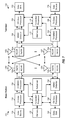
FIG. 8 shows a block diagram of a design of TX data processor 710, which may also be used for TX data processor 780 in FIG. 7. Within TX data processor 710, a packet partitioning unit 810 may receive a packet for transmission, partition the packet into t subpackets, e.g., as shown in equation (2), and provide the t subpackets to t processing sections 820 a through 820 t.
Within processing section 820 a for subpacket 0, a CRC generator 822 may generate a CRC for the subpacket and provide a formatted subpacket having the CRC appended to the subpacket. A forward error correction (FEC) encoder 824 may receive the formatted subpacket, encode the subpacket in accordance with an FEC code, and provide a coded subpacket. The FEC code may comprise a Turbo code, a convolutional code, a low density parity check (LDPC) code, a block code, etc. An interleaver 826 may interleave or reorder the bits in the coded subpacket based on an interleaving scheme. A repetition unit 828 may repeat the bits from interleaver 826, if necessary, to obtain the desired total number of bits. A scrambler 830 may scramble the bits from unit 828 to randomize the data. Scrambler 830 may generate a scrambling sequence based on a linear feedback shift register (LFSR), which may be initialized at the start of the subpacket with a seed value determined based on a MAC ID of terminal 120, a sector ID or pilot phase of a serving sector/base station, a packet format index for the packet, a frame index of the first PHY frame in which the packet is sent, and/or some other parameter. A symbol mapper 832 may map the scrambled bits to modulation symbols based on a selected modulation scheme such as QPSK, 16-QAM, 64-QAM, etc. Symbol mapper 832 may provide an output subpacket of modulation symbols. Each remaining processing section 820 may similarly process its subpacket and provide a corresponding output subpacket of modulation symbols.
A subpacket-to-tile mapper 840 may receive all t output subpackets from processing sections 820 a through 820 t. Mapper 840 may map each subpacket to all of a subset of the NTILES tiles assigned for the packet. For each tile, mapper 840 may determine at least one subpacket mapped to that tile and may map the modulation symbols in the at least one subpacket to the proper hop-ports and OFDM symbol periods in the tile, e.g., as shown in equation (3) and FIG. 5.
FIG. 9 shows a block diagram of a design of RX data processor 760, which may also be used for RX data processor 740 in FIG. 7. Within RX data processor 760, a tile-to-subpacket demapper 910 may receive detected symbols for the NTILES tiles used for a packet, perform demapping from tiles to subpackets, and provide the detected symbols for the t subpackets to t processing sections 920 a through 920 t.
Within processing section 920 a for subpacket 0, a log-likelihood ratio (LLR) computation unit 922 may receive the detected symbols for subpacket 0 and may compute LLRs for code bits for this subpacket based on the detected symbols. The LLR for each code bit may indicate the likelihood of that code bit being zero (‘0’) or one (‘1’) given the detected symbol for the code bit. A descrambler 924 may descramble the LLRs based on the scrambling sequence used for the subpacket. An LLR combiner 926 may combine LLRs for repeated code bits, which may have been sent in later HARQ transmissions. A deinterleaver 928 may deinterleave the LLRs from unit 926 in a manner complementary to the interleaving by interleaver 826 in FIG. 8. An FEC decoder 930 may decode the deinterleaved LLRs in accordance with an FEC code used for the subpacket and provide a decoded subpacket. A CRC checker 932 may check the decoded subpacket and provide decoding status for the subpacket. Each remaining processing section 920 may similarly process its subpacket and provide a corresponding decoded subpacket.
A multiplexer (Mux) 940 may assemble all t decoded subpackets from processing sections 920 a through 920 t and provide a decoded packet. In one design, an acknowledgement (ACK) may be sent for each subpacket decoded correctly. All t subpackets may be acknowledged together. The subpackets decoded in error may be resent in a subsequent HARQ transmission.
FIG. 10 shows a design of a process 1000 for transmitting data. Process 1000 may be performed by a transmitter, which may be a base station for a forward link transmission or a terminal for a reverse link transmission. Resources assigned for transmission of a packet may be determined (block 1012). The packet may be partitioned into multiple subpackets (block 1014). Each subpacket may be encoded based on an FEC code to obtain a corresponding coded subpacket (block 1016). The multiple coded subpackets may be mapped to the assigned resources, with at least one coded subpacket being mapped to a subset of the assigned resources (block 1018).
The assigned resources may include multiple tiles. For block 1018, each subpacket may be mapped to (i) a different subset of the multiple tiles, (ii) a particular minimum number of tiles, (iii) all of the multiple tiles if fewer than the particular minimum number of tiles, (iv) an equal number of tiles, or (v) a combination thereof. The multiple tiles may be arranged into a first group of an integer multiple of t tiles and a second group of remaining tiles, where t is the number of subpackets. A subset of the t subpackets may be mapped to each tile in the first group, and all of the t subpackets may be mapped to each tile in the second group. For each tile, at least one subpacket mapped to that tile may be determined and may be distributed across the tile, e.g., by cycling through the at least one subpacket and mapping one subpacket to each available transmission unit in the tile.
FIG. 11 shows a design of an apparatus 1100 for transmitting data. Apparatus 1100 includes means for determining resources assigned for transmission of a packet (module 1112), means for partitioning the packet into multiple subpackets (module 1114), means for encoding each subpacket based on an FEC code to obtain a corresponding coded subpacket (module 1116), and means for mapping the multiple coded subpackets to the assigned resources, with at least one coded subpacket being mapped to a subset of the assigned resources (module 1118).
FIG. 12 shows a design of a process 1200 for receiving data. Process 1200 may be performed by a receiver, which may be a terminal for a forward link transmission or a base station for a reverse link transmission. Resources assigned for transmission of a packet may be determined (block 1212). Multiple subpackets of the packet may be received via the assigned resources (block 1214). The multiple subpackets may be demapped from the assigned resources, with at least one subpacket being demapped from a subset of the assigned resources (block 1216). The multiple subpackets may be processed after demapping to recover the packet (block 1218).
The assigned resources may include multiple tiles. For block 1216, each subpacket may be demapped from (i) a different subset of the multiple tiles, (ii) a particular minimum number of tiles, (iii) all of the multiple tiles if fewer than the particular minimum number of tiles, (iv) an equal number of tiles, or (v) a combination thereof. For each tile, at least one subpacket mapped to that tile may be determined and may be demapped from across the tile.
For block 1218, demodulation may be performed for each tile, e.g., on a tile-by-tile basis. Decoding may be performed for each subpacket when all tiles to which the subpacket is mapped have been demodulated, without waiting for all of the assigned tiles to be demodulated. Each subpacket may be decoded based on an FEC code to obtain a corresponding decoded subpacket.
FIG. 13 shows a design of an apparatus 1300 for receiving data. Apparatus 1300 includes means for determining resources assigned for transmission of a packet (module 1312), means for receiving multiple subpackets of the packet via the assigned resources (module 1314), means for demapping the multiple subpackets from the assigned resources, with at least one subpacket being demapped from a subset of the assigned resources (module 1316), and means for processing the multiple subpackets after demapping to recover the packet (module 1318).
The modules in FIGS. 11 and 13 may comprise processors, electronics devices, hardware devices, electronics components, logical circuits, memories, etc., or any combination thereof.
The techniques described herein may be implemented by various means. For example, these techniques may be implemented in hardware, firmware, software, or a combination thereof For a hardware implementation, the processing units used to perform the techniques at an entity (e.g., a base station or a terminal) may be implemented within one or more application specific integrated circuits (ASICs), digital signal processors (DSPs), digital signal processing devices (DSPDs), programmable logic devices (PLDs), field programmable gate arrays (FPGAs), processors, controllers, micro-controllers, microprocessors, electronic devices, other electronic units designed to perform the functions described herein, a computer, or a combination thereof
For a firmware and/or software implementation, the techniques may be implemented with code (e.g., procedures, functions, modules, instructions, etc.) that performs the functions described herein. In general, any computer/processor-readable medium tangibly embodying firmware and/or software code may be used in implementing the techniques described herein. For example, the firmware and/or software code may be stored in a memory (e.g., memory 732 or 772 in FIG. 2) and executed by a processor (e.g., processor 730 or 770). The memory may be implemented within the processor or external to the processor. The firmware and/or software code may also be stored in a computer/processor-readable medium such as random access memory (RAM), read-only memory (ROM), non-volatile random access memory (NVRAM), programmable read-only memory (PROM), electrically erasable PROM (EEPROM), FLASH memory, floppy disk, compact disc (CD), digital versatile disc (DVD), magnetic or optical data storage device, etc. The code may be executable by one or more computers/processors and may cause the computer/processor(s) to perform certain aspects of the functionality described herein.
The previous description of the disclosure is provided to enable any person skilled in the art to make or use the disclosure. Various modifications to the disclosure will be readily apparent to those skilled in the art, and the generic principles defined herein may be applied to other variations without departing from the spirit or scope of the disclosure. Thus, the disclosure is not intended to be limited to the examples and designs described herein but is to be accorded the widest scope consistent with the principles and novel features disclosed herein.

Claims (36)

1. An apparatus for communication, comprising:
at least one processor configured to determine resources assigned for transmission of a packet, to partition the packet into multiple subpackets, and to map the multiple subpackets to the assigned resources, with at least one subpacket being mapped to a subset of the assigned resources; and
a memory coupled to the at least one processor;
wherein the assigned resources comprise multiple tiles, each tile corresponding to a block of time frequency resources; and
wherein the at least one processor is configured to arrange the multiple tiles into a first group of at least two tiles and a second group of remaining tiles, to map a subset of the multiple subpackets to each tile in the second group, and to map all of the multiple subpackets to each tile in the first group.
2. The apparatus of claim 1, wherein the at least one processor is configured to encode each subpacket based on a forward error correction (FEC) code to obtain a corresponding coded subpacket.
3. The apparatus of claim 1, wherein each tile corresponds to a block of contiguous time frequency resources.
4. The apparatus of claim 3, wherein the at least one processor is configured to map each of the multiple subpackets to a particular minimum number of tiles greater than one or to all of the multiple tiles if fewer than the particular minimum number of tiles are available.
5. The apparatus of claim 1, wherein the tiles correspond to blocks of time frequency resources distributed across system bandwidth.
6. The apparatus of claim 1, wherein the at least one processor is configured to map each of the multiple subpackets to a different subset of the multiple tiles.
7. The apparatus of claim 1, wherein the at least one processor is configured to map each of the multiple subpackets to an equal number of tiles greater than one.
8. The apparatus of claim 1, wherein the first group includes an integer multiple oft tiles, where t is the number of subpackets.
9. The apparatus of claim 1, wherein the at least one processor is configured to determine a plurality of subpackets mapped to one of the tiles and to distribute a portion of each of the plurality of subpackets across the one tile.
10. The apparatus of claim 1, wherein for each of the multiple tiles the at least one processor is configured to distribute the at least one subpacket across the one tile by cycling through the at least one subpacket and mapping one subpacket to each available transmission unit in the one tile.
11. A method of transmitting data, comprising:
determining resources assigned for transmission of a packet;
partitioning the packet into multiple subpackets; and
mapping the multiple subpackets to the assigned resources, with at least one subpacket being mapped to a subset of the assigned resources;
wherein the assigned resources comprise multiple tiles, and wherein the mapping the multiple subpackets comprises:
arranging the multiple tiles into a first group of an integer multiple of t tiles and a second group of remaining tiles, where t is the number of subpackets,
mapping a subset of the multiple subpackets to each tile in the second group, and
mapping all of the multiple subpackets to each tile in the first group.
12. The method of claim 11, further comprising:
encoding each subpacket based on a forward error correction (FEC) code to obtain a corresponding coded subpacket.
13. The method of claim 11, wherein the mapping the multiple subpackets comprises
mapping each of the multiple subpackets to at least one of a different subset of the multiple tiles, an equal number of tiles, a particular minimum number of tiles, and all of the multiple tiles if fewer than the particular minimum number of tiles.
14. An apparatus for communication, comprising:
means for determining resources assigned for transmission of a packet;
means for partitioning the packet into multiple subpackets; and
means for mapping the multiple subpackets to the assigned resources, with at least one subpacket being mapped to a subset of the assigned resources;
wherein the assigned resources comprise multiple tiles, and wherein the means for mapping the multiple subpackets comprises
means for arranging the multiple tiles into a first group of an integer multiple of t tiles and a second group of remaining tiles, where t is the number of subpackets,
means for mapping a subset of the multiple subpackets to each tile in the second group, and
means for mapping all of the multiple subpackets to each tile in the first group.
15. The apparatus of claim 14, further comprising:
means for encoding each subpacket based on a forward error correction (FEC) code to obtain a corresponding coded subpacket.
16. The apparatus of claim 14, wherein the means for mapping the multiple subpackets comprises
means for mapping each of the multiple subpackets to at least one of a different subset of the multiple tiles, an equal number of tiles, a particular minimum number of tiles, and all of the multiple tiles if fewer than the particular minimum number of tiles.
17. A computer program product, comprising:
a non-transitory computer-readable medium comprising:
code for causing at least one computer to determine resources assigned for transmission of a packet, wherein the assigned resources comprise multiple tiles, each tile corresponding to a block of time frequency resources;
code for causing the at least one computer to partition the packet into multiple subpackets;
code for causing the at least one computer to map the multiple subpackets to the assigned resources, with at least one subpacket being mapped to a subset of the assigned resources; and
code for causing the at least one computer to arrange the multiple tiles into a first group of at least two tiles and a second group of remaining tiles;
code for causing the at least one computer to map a subset of the multiple subpackets to each tile in the second group; and
code for causing the at least one computer to map all of the multiple subpackets to each tile in the first group.
18. An apparatus for communication, comprising:
at least one processor configured to determine resources assigned for transmission of a packet, to receive multiple subpackets of the packet via the assigned resources, to demap the multiple subpackets from the assigned resources, with at least one subpacket being demapped from a subset of the assigned resources, and to process the multiple subpackets after demapping to recover the packet; and
a memory coupled to the at least one processors;
wherein the assigned resources comprise multiple tiles, each tile corresponding to a block of time frequency resources; and
wherein the at least one processor is configured to perform demodulation for each of the multiple tiles and to perform decoding for each of the multiple subpackets when all tiles to which the subpacket is mapped have been demodulated without waiting for all of the multiple tiles to be demodulated.
19. The apparatus of claim 18, wherein the at least one processor is configured to decode each subpacket based on a forward error correction (FEC) code to obtain a corresponding decoded subpacket.
20. The apparatus of claim 18, wherein the at least one processor is configured to demap each of the multiple subpackets from a different subset of the multiple tiles.
21. The apparatus of claim 18, wherein the at least one processor is configured to demap each of the multiple subpackets from a particular minimum number of tiles or from all of the multiple tiles if fewer than the particular minimum number of tiles.
22. The apparatus of claim 18, wherein the at least one processor is configured to demap each of the multiple subpackets from an equal number of tiles.
23. The apparatus of claim 18, wherein for each of the multiple tiles the at least one processor is configured to determine at least one subpacket mapped to the tile and to demap the at least one subpacket from across the tile.
24. A method of receiving data, comprising:
determining resources assigned for transmission of a packet;
receiving multiple subpackets of the packet via the assigned resources;
demapping the multiple subpackets from the assigned resources, with at least one subpacket being demapped from a subset of the assigned resources; and
processing the multiple subpackets after demapping to recover the packet;
wherein the assigned resources comprise multiple tiles, and wherein the processing the multiple subpackets comprises:
performing demodulation for each of the multiple tiles, and
performing decoding for each of the multiple subpackets when all tiles to which the subpacket is mapped have been demodulated without waiting for all of the multiple tiles to be demodulated.
25. The method of claim 24, wherein the processing the multiple subpackets comprises decoding each subpacket based on a forward error correction (FEC) code to obtain a corresponding decoded subpacket.
26. The method of claim 24, wherein the demapping the multiple subpackets comprises
demapping each of the multiple subpackets from at least one of a different subset of the multiple tiles, a particular minimum number of tiles, all of the multiple tiles if fewer than the particular minimum number of tiles, and an equal number of tiles.
27. An apparatus for communication, comprising:
means for determining resources assigned for transmission of a packet;
means for receiving multiple subpackets of the packet via the assigned resources;
means for demapping the multiple subpackets from the assigned resources, with at least one subpacket being demapped from a subset of the assigned resources; and
means for processing the multiple subpackets after demapping to recover the packet;
wherein the assigned resources comprise multiple tiles, and wherein the means for processing the multiple subpackets comprises
means for performing demodulation for each of the multiple tiles; and
means for performing decoding for each of the multiple subpackets when all tiles to which the subpacket is mapped have been demodulated without waiting for all of the multiple tiles to be demodulated.
28. The apparatus of claim 27, wherein the means for processing the multiple subpackets comprises means for decoding each subpacket based on a forward error correction (FEC) code to obtain a corresponding decoded subpacket.
29. The apparatus of claim 27, wherein the means for demapping the multiple subpackets comprises
means for demapping each of the multiple subpackets from at least one of a different subset of the multiple tiles, a particular minimum number of tiles, all of the multiple tiles if fewer than the particular minimum number of tiles, and an equal number of tiles.
30. A computer program product, comprising:
a non-transitory computer-readable medium comprising:
code for causing at least one computer to determine resources assigned for transmission of a packet, the assigned resources comprising multiple tiles;
code for causing the at least one computer to receive multiple subpackets of the packet via the assigned resources;
code for causing the at least one computer to demap the multiple subpackets from the assigned resources, with at least one subpacket being demapped from a subset of the assigned resources;
code for causing the at least one computer to process the multiple subpackets after demapping to recover the packet;
code for performing demodulation for each of the multiple tiles, and
code for performing decoding for each of the multiple subpackets when all tiles to which the subpacket is mapped have been demodulated without waiting for all of the multiple tiles to be demodulated.
31. A communication apparatus comprising:
at least one processor configured to determine resources assigned for transmission of a packet, to partition the packet into multiple subpackets, and to map the multiple subpackets to the assigned resources, with at least one subpacket being mapped to a subset of the assigned resources; and
a memory coupled to the at least one processor;
wherein the assigned resources comprise multiple tiles each corresponding to a block of contiguous time frequency resources; and
wherein the at least one processor is configured to map each of the multiple subpackets to a particular minimum number of tiles greater than one or to all of the multiple tiles if fewer than the particular minimum number of tiles are available; and
wherein the at least one processor is configured to determine a plurality of subpackets mapped to one of the tiles and to distribute a portion of each of the plurality of subpackets across the one tile.
32. The apparatus of claim 31 wherein the at least one processor is configured to map each of the multiple subpackets to an equal number of tiles greater than one.
33. An communication apparatus comprising:
means for determining resources assigned for transmission of a packet, means for partitioning the packet into multiple subpackets, and means for mapping the multiple subpackets to the assigned resources, with at least one subpacket being mapped to a subset of the assigned resources; and
a memory coupled to the at least one processor;
wherein the assigned resources comprise multiple tiles each corresponding to a block of contiguous time frequency resources; and
wherein the means for mapping are configured to map each of the multiple subpackets to a particular minimum number of tiles greater than one or to all of the multiple tiles if fewer than the particular minimum number of tiles are available; and
wherein the means for mapping are configured to determine a plurality of subpackets mapped to one of the tiles and to distribute a portion of each of the plurality of subpackets across the one tile.
34. The apparatus of claim 33 wherein the means for mapping are configured to map each of the multiple subpackets to an equal number of tiles greater than one.
35. A computer program product residing on a non-transitory processor-readable medium of a communication apparatus and comprising processor-readable instructions configured to cause a processor to:
determine resources assigned for transmission of a packet, the assigned resources comprising multiple tiles each corresponding to a block of contiguous time frequency resources;
partition the packet into multiple subpackets; and
map the multiple subpackets to the assigned resources, with each of the multiple subpackets being mapped to a particular minimum number of tiles greater than one or to all of the multiple tiles if fewer than the particular minimum number of tiles are available; and
determine a plurality of subpackets mapped to one of the tiles and distribute a portion of each of the plurality of subpackets across the one tile.
36. The computer program product of claim 35 wherein the instructions configured to cause the processor to map the multiple subpackets are configured to cause the processor to map each of the multiple subpackets to an equal number of tiles greater than one.
US11/968,631 2007-01-05 2008-01-02 Mapping of subpackets to resources in a communication system Active 2029-05-26 US8320407B2 (en)

Priority Applications (12)

Application Number Priority Date Filing Date Title
US11/968,631 US8320407B2 (en) 2007-01-05 2008-01-02 Mapping of subpackets to resources in a communication system
PCT/US2008/050080 WO2008086074A1 (en) 2007-01-05 2008-01-03 Mapping of subpackets to resources in a communication system
BRPI0806485-7A BRPI0806485A2 (en) 2007-01-05 2008-01-03 mapping of subpackages on features in a communication system
EP08713437A EP2122930A1 (en) 2007-01-05 2008-01-03 Mapping of subpackets to resources in a communication system
CN2008800017823A CN101589582B (en) 2007-01-05 2008-01-03 Mapping of subpackets to resources in a communication system
CA2672317A CA2672317C (en) 2007-01-05 2008-01-03 Mapping of subpackets to resources in a communication system
KR1020097015415A KR101107897B1 (en) 2007-01-05 2008-01-03 Mapping of subpackets to resources in a communication system
JP2009544966A JP2010516109A (en) 2007-01-05 2008-01-03 Mapping of subpackets to resources in a communication system
TW97100515A TWI377816B (en) 2007-01-05 2008-01-04 Mapping of subpackets to resources in a communication system
JP2013078817A JP5607203B2 (en) 2007-01-05 2013-04-04 Mapping subpackets to resources in a communication system
JP2014139125A JP5763249B2 (en) 2007-01-05 2014-07-04 Mapping subpackets to resources in a communication system
JP2014139126A JP2014222918A (en) 2007-01-05 2014-07-04 Mapping of subpackets to resources in communication system

Applications Claiming Priority (3)

Application Number Priority Date Filing Date Title
US88370207P 2007-01-05 2007-01-05
US88375807P 2007-01-05 2007-01-05
US11/968,631 US8320407B2 (en) 2007-01-05 2008-01-02 Mapping of subpackets to resources in a communication system

Publications (2)

Publication Number Publication Date
US20080240159A1 US20080240159A1 (en) 2008-10-02
US8320407B2 true US8320407B2 (en) 2012-11-27

Family

ID=39345226

Family Applications (1)

Application Number Title Priority Date Filing Date
US11/968,631 Active 2029-05-26 US8320407B2 (en) 2007-01-05 2008-01-02 Mapping of subpackets to resources in a communication system

Country Status (9)

Country Link
US (1) US8320407B2 (en)
EP (1) EP2122930A1 (en)
JP (4) JP2010516109A (en)
KR (1) KR101107897B1 (en)
CN (1) CN101589582B (en)
BR (1) BRPI0806485A2 (en)
CA (1) CA2672317C (en)
TW (1) TWI377816B (en)
WO (1) WO2008086074A1 (en)

Cited By (3)

* Cited by examiner, † Cited by third party
Publication number Priority date Publication date Assignee Title
US8929551B2 (en) 2007-01-05 2015-01-06 Qualcomm Incorporated Pilot transmission in a wireless communication system
US9237565B2 (en) 2010-05-10 2016-01-12 Telefonaktiebolaget L M Ericsson (Publ) System and method for allocating transmission resources
US9295008B2 (en) 2007-01-04 2016-03-22 Qualcomm Incorporated Method and apparatus for utilizing other sector interference (OSI) indication

Families Citing this family (19)

* Cited by examiner, † Cited by third party
Publication number Priority date Publication date Assignee Title
US8681749B2 (en) * 2007-01-04 2014-03-25 Qualcomm Incorporated Control resource mapping for a wireless communication system
US7885176B2 (en) * 2007-06-01 2011-02-08 Samsung Electronics Co., Ltd. Methods and apparatus for mapping modulation symbols to resources in OFDM systems
KR101505193B1 (en) * 2007-06-18 2015-03-23 삼성전자주식회사 Symbol Transmission Method and Apparatus for used in Orthogonal Frequency Division Multiplex Access Systems
KR20090024623A (en) * 2007-09-04 2009-03-09 한국전자통신연구원 Frame structure for fast wireless communication system and apparatus for fast wireless communication using the frame
US20090122758A1 (en) * 2007-11-14 2009-05-14 Jack Smith Method and Apparatus for Transmitting HARQ Sub-Packets in a Wireless Communication System
KR101387534B1 (en) * 2008-01-03 2014-04-21 엘지전자 주식회사 Symbol mapping method for repetition channel coding
US8082478B2 (en) * 2008-01-24 2011-12-20 Infineon Technologies Ag Retransmission of erroneous data
US8520500B2 (en) * 2008-03-28 2013-08-27 Qualcomm Incorporated Buffered demod and demap functions
US20090268910A1 (en) * 2008-04-28 2009-10-29 Samsung Electronics Co., Ltd. Apparatus and method for initialization of a scrambling sequence for a downlink reference signal in a wireless network
US8867565B2 (en) * 2008-08-21 2014-10-21 Qualcomm Incorporated MIMO and SDMA signaling for wireless very high throughput systems
KR101587281B1 (en) * 2009-03-12 2016-01-20 삼성전자주식회사 Method for encoding contorl information in a communication system and transmission/reception method and apparatus thereof
US8510621B2 (en) * 2009-12-29 2013-08-13 Industrial Technology Research Institute Method and apparatus for providing resource unit based data block partition
CN102202029B (en) * 2010-03-24 2015-01-28 中兴通讯股份有限公司 Channel estimation method and device for orthogonal frequency division multiplexing system
KR101655269B1 (en) * 2010-05-28 2016-09-07 삼성전자주식회사 Apparatus and method for resource segmetation in wireless communication system
US8588347B1 (en) 2010-06-23 2013-11-19 Marvell International Ltd. Systems and methods for performing efficient blind decoding at a wireless receiver
US10638464B2 (en) 2011-04-01 2020-04-28 Futurewei Technologies, Inc. System and method for transmission and reception of control channels in a communications system
JP6465810B2 (en) * 2012-12-21 2019-02-06 サムスン エレクトロニクス カンパニー リミテッド Signal transmission / reception method and apparatus using multiple modulation techniques in wireless communication system
JP6317696B2 (en) * 2015-03-16 2018-04-25 株式会社東芝 Communication apparatus and communication system
DE102018206159B3 (en) 2018-04-20 2019-09-19 Fraunhofer-Gesellschaft zur Förderung der angewandten Forschung e.V. Packet detector / decoder for a radio transmission system

Citations (50)

* Cited by examiner, † Cited by third party
Publication number Priority date Publication date Assignee Title
US4926416A (en) * 1987-12-18 1990-05-15 Alcatel N.V. Method and facilities for hybrid packet switching
EP0650304A2 (en) 1993-10-25 1995-04-26 Telefonaktiebolaget Lm Ericsson A frequency hopping control channel in a radio communication system
JPH10502507A (en) 1994-07-05 1998-03-03 エリクソン インコーポレイテッド Method and apparatus for key translation to discriminate between different networks
WO1998052326A2 (en) 1997-05-13 1998-11-19 Nokia Networks Oy A method for packet switched data transmission
US5864577A (en) * 1994-06-24 1999-01-26 Thomson-Csf Method, transmitter and receiver for the transmission of information in packets having a header and subpackets
US5896357A (en) * 1996-07-31 1999-04-20 Asahi Kogaku Kogyo Kabushiki Kaisha Shutter opening mechanism of data recording/reproducing device
EP0917305A2 (en) 1997-09-22 1999-05-19 Sony Corporation Communication method, transmitting method, receiving method, base station and terminal device
WO2000013427A2 (en) 1998-08-26 2000-03-09 Samsung Electronics Co., Ltd. Device and method for communicating packet voice data in mobile communication system
KR20000026410A (en) 1998-10-20 2000-05-15 윤종용 Variable channel device for wideband cord division multiple access system
WO2001001596A1 (en) 1999-06-30 2001-01-04 Qualcomm Incorporated Method and apparatus for fast wcdma acquisition
WO2001017125A1 (en) 1999-08-31 2001-03-08 Qualcomm Incorporated Method and apparatus for reducing pilot search times utilizing mobile station location information
WO2001026269A1 (en) 1999-10-02 2001-04-12 Samsung Electronics Co., Ltd Apparatus and method for gating data on a control channel in a cdma communication system
US6278685B1 (en) * 1999-08-19 2001-08-21 Intellon Corporation Robust transmission mode
RU99126427A (en) 1997-05-13 2001-10-27 Нокиа Нетворкс Ой METHOD OF DATA TRANSFER WITH PACKAGE SWITCHING
US6400699B1 (en) * 2000-09-12 2002-06-04 Iospan Wireless, Inc. Transmission scheduler for a multiple antenna wireless cellular network
WO2002058300A1 (en) 2001-01-19 2002-07-25 Broadstorm Telecommunications, Inc. Multi-carrier communication with time division multiplexing and carrier-selective loading
RU2191477C2 (en) 1995-09-01 2002-10-20 ТЕЛЕФОНАКТИЕБОЛАГЕТ ЛМ ЭРИКССОН (пабл.) Reconfiguration of systems operating in radio communication systems
WO2003001741A1 (en) 2001-06-20 2003-01-03 Motorola, Inc. Method and apparatus for controlling multiple logical data flow in a variable data rate environment
EP1289328A1 (en) 2001-08-28 2003-03-05 Lucent Technologies Inc. A method of sending control information in a wireless telecommunications network, and corresponding apparatus
WO2003032564A2 (en) 2001-10-05 2003-04-17 Qualcomm Incorporated Flexible arq for packet data transmission
US20040062321A1 (en) 1997-04-17 2004-04-01 Takehiro Nakamura Base station apparatus of mobile communication system
US6768713B1 (en) 1999-09-13 2004-07-27 France Telecom Orthogonal frequency division multiplexing receiver with iterative channel estimation and a corresponding method
RU2242091C2 (en) 1999-10-02 2004-12-10 Самсунг Электроникс Ко., Лтд. Device and method for gating data transferred over control channel in cdma communication system
US6845104B2 (en) * 2000-06-14 2005-01-18 Ipr Licensing, Inc. Receiver for time division multiplex system without explicit time slot assignment
US20050084000A1 (en) 2003-10-17 2005-04-21 Krauss Thomas P. Method and apparatus for transmission and reception within an OFDM communication system
WO2005046259A2 (en) 2003-11-10 2005-05-19 Koninklijke Philips Electronics N.V. A method and apparatus for mitigating p2p interference in p2p-enabled communication systems
US20050135324A1 (en) 2003-12-17 2005-06-23 Yun-Hee Kim Apparatus for OFDMA transmission and reception for coherent detection in uplink of wireless communication system and method thereof
US20050163194A1 (en) 2004-01-28 2005-07-28 Qualcomm Incorporated Interference estimation in a wireless communication system
US6928066B1 (en) 1998-11-09 2005-08-09 Samsung Electronics Co., Ltd. RSMA control device and method for mobile communication system
WO2005076552A1 (en) 2004-01-20 2005-08-18 Qualcomm Incorporated Network using randomized time division duplexing
JP2005333677A (en) 1997-04-17 2005-12-02 Ntt Docomo Inc Base station apparatus in mobile communication system
WO2006007318A1 (en) 2004-06-18 2006-01-19 Qualcomm Incorporated Power control for a wireless communication system utilizing orthogonal multiplexing
US20060109810A1 (en) 2004-11-24 2006-05-25 Au Jean P Preamble miss detection in transmission of multi-slot packets
JP2006203355A (en) 2005-01-18 2006-08-03 Toshiba Corp Wireless communication system and wireless transmission apparatus
RU2282943C2 (en) 2001-02-09 2006-08-27 Нокиа Корпорейшн Improved method and device for transferring information in packet radio communication service
WO2006094299A1 (en) 2005-03-04 2006-09-08 Qualcomm Incorporated Power control and quality of service (qos) implementation in a communication system
US20060209973A1 (en) 2005-03-17 2006-09-21 Alexei Gorokhov Pilot signal transmission for an orthogonal frequency division wireless communication system
WO2006099546A1 (en) 2005-03-15 2006-09-21 Qualcomm Incorporated Interference information from multiple sectors for power control
WO2006099547A1 (en) 2005-03-15 2006-09-21 Qualcomm Incorporated Interference control in a wireless communication system
JP2006311465A (en) 2005-03-31 2006-11-09 Ntt Docomo Inc Transmitting apparatus and radio resource allocation method
WO2006125150A2 (en) 2005-05-18 2006-11-23 Qualcomm Incorporated Softer and soft handoff in an orthogonal frequency division wireless communication system
WO2006130742A1 (en) 2005-05-31 2006-12-07 Qualcomm Incorporated Assignment acknowledgement for a wireless communication system
US20060274691A1 (en) * 2005-06-07 2006-12-07 Naguib Ayman F Reception of H-ARQ transmissions with interference cancellation in a quasi-orthogonal communication system
WO2006133598A1 (en) 2005-06-15 2006-12-21 Huawei Technologies Co., Ltd. Method and system for allocating communication resources
US20060285503A1 (en) 2005-03-15 2006-12-21 Murat Mese Interference control in a wireless communication system
CA2605556A1 (en) 2005-06-22 2006-12-28 Yong-Jun Kwak Method and transmission apparatus for allocating resources to transmit uplink packet data in an orthogonal frequency division multiplexing system
WO2007146930A2 (en) 2006-06-13 2007-12-21 Qualcomm Incorporated Reverse link pilot transmission for a wireless communication system
US20080167040A1 (en) 2007-01-04 2008-07-10 Qualcomm Incorporated Control resource mapping for a wireless communication system
US20080165969A1 (en) 2007-01-05 2008-07-10 Qualcomm Incorporated Pilot transmission in a wireless communication system
US20080166969A1 (en) 2007-01-04 2008-07-10 Qualcomm Incorporated Method and apparatus for utilizing other sector interference (osi) indication

Family Cites Families (5)

* Cited by examiner, † Cited by third party
Publication number Priority date Publication date Assignee Title
JPH07183862A (en) * 1993-12-22 1995-07-21 Toshiba Corp Error correcting method of frequency division multiplexing transmission and transmission system using same
EP1424864A1 (en) * 2002-11-29 2004-06-02 Siemens Mobile Communications S.p.A. Method of resource indication in mobile communications systems having cells operating with different radio access techniques
ATE438970T1 (en) * 2004-06-29 2009-08-15 Ericsson Telefon Ab L M METHOD FOR PROCESSING PACKET-BASED DATA AND TRANSMISSION AND RECEIPT
WO2006020611A2 (en) * 2004-08-13 2006-02-23 Glasslock, Inc. Retrofit glass fragment catching system
WO2006046894A1 (en) * 2004-10-29 2006-05-04 Telefonaktiebolaget Lm Ericsson (Publ) Resource allocation in communication networks

Patent Citations (61)

* Cited by examiner, † Cited by third party
Publication number Priority date Publication date Assignee Title
US4926416A (en) * 1987-12-18 1990-05-15 Alcatel N.V. Method and facilities for hybrid packet switching
EP0650304A2 (en) 1993-10-25 1995-04-26 Telefonaktiebolaget Lm Ericsson A frequency hopping control channel in a radio communication system
US5864577A (en) * 1994-06-24 1999-01-26 Thomson-Csf Method, transmitter and receiver for the transmission of information in packets having a header and subpackets
JPH10502507A (en) 1994-07-05 1998-03-03 エリクソン インコーポレイテッド Method and apparatus for key translation to discriminate between different networks
RU2191477C2 (en) 1995-09-01 2002-10-20 ТЕЛЕФОНАКТИЕБОЛАГЕТ ЛМ ЭРИКССОН (пабл.) Reconfiguration of systems operating in radio communication systems
US5896357A (en) * 1996-07-31 1999-04-20 Asahi Kogaku Kogyo Kabushiki Kaisha Shutter opening mechanism of data recording/reproducing device
US20040062321A1 (en) 1997-04-17 2004-04-01 Takehiro Nakamura Base station apparatus of mobile communication system
JP2005333677A (en) 1997-04-17 2005-12-02 Ntt Docomo Inc Base station apparatus in mobile communication system
WO1998052326A2 (en) 1997-05-13 1998-11-19 Nokia Networks Oy A method for packet switched data transmission
RU99126427A (en) 1997-05-13 2001-10-27 Нокиа Нетворкс Ой METHOD OF DATA TRANSFER WITH PACKAGE SWITCHING
EP0917305A2 (en) 1997-09-22 1999-05-19 Sony Corporation Communication method, transmitting method, receiving method, base station and terminal device
WO2000013427A2 (en) 1998-08-26 2000-03-09 Samsung Electronics Co., Ltd. Device and method for communicating packet voice data in mobile communication system
RU2187205C2 (en) 1998-08-26 2002-08-10 Самсунг Электроникс Ко., Лтд. Device and method for transmitting voice data bursts in mobile communication system
KR20000026410A (en) 1998-10-20 2000-05-15 윤종용 Variable channel device for wideband cord division multiple access system
US6928066B1 (en) 1998-11-09 2005-08-09 Samsung Electronics Co., Ltd. RSMA control device and method for mobile communication system
RU2250564C2 (en) 1999-06-30 2005-04-20 Квэлкомм Инкорпорейтед Method and device for fast synchronization in wide-band code-division multiple access system
WO2001001596A1 (en) 1999-06-30 2001-01-04 Qualcomm Incorporated Method and apparatus for fast wcdma acquisition
US6278685B1 (en) * 1999-08-19 2001-08-21 Intellon Corporation Robust transmission mode
WO2001017125A1 (en) 1999-08-31 2001-03-08 Qualcomm Incorporated Method and apparatus for reducing pilot search times utilizing mobile station location information
RU2257008C2 (en) 1999-08-31 2005-07-20 Квэлкомм Инкорпорейтед Method for decreasing search time of pilot signal with use of information about position of mobile station and device for realization of said method
US6768713B1 (en) 1999-09-13 2004-07-27 France Telecom Orthogonal frequency division multiplexing receiver with iterative channel estimation and a corresponding method
WO2001026269A1 (en) 1999-10-02 2001-04-12 Samsung Electronics Co., Ltd Apparatus and method for gating data on a control channel in a cdma communication system
RU2242091C2 (en) 1999-10-02 2004-12-10 Самсунг Электроникс Ко., Лтд. Device and method for gating data transferred over control channel in cdma communication system
US6845104B2 (en) * 2000-06-14 2005-01-18 Ipr Licensing, Inc. Receiver for time division multiplex system without explicit time slot assignment
US6400699B1 (en) * 2000-09-12 2002-06-04 Iospan Wireless, Inc. Transmission scheduler for a multiple antenna wireless cellular network
WO2002058300A1 (en) 2001-01-19 2002-07-25 Broadstorm Telecommunications, Inc. Multi-carrier communication with time division multiplexing and carrier-selective loading
RU2282943C2 (en) 2001-02-09 2006-08-27 Нокиа Корпорейшн Improved method and device for transferring information in packet radio communication service
WO2003001741A1 (en) 2001-06-20 2003-01-03 Motorola, Inc. Method and apparatus for controlling multiple logical data flow in a variable data rate environment
EP1289328A1 (en) 2001-08-28 2003-03-05 Lucent Technologies Inc. A method of sending control information in a wireless telecommunications network, and corresponding apparatus
WO2003032564A2 (en) 2001-10-05 2003-04-17 Qualcomm Incorporated Flexible arq for packet data transmission
US20050084000A1 (en) 2003-10-17 2005-04-21 Krauss Thomas P. Method and apparatus for transmission and reception within an OFDM communication system
US7242722B2 (en) 2003-10-17 2007-07-10 Motorola, Inc. Method and apparatus for transmission and reception within an OFDM communication system
WO2005046259A2 (en) 2003-11-10 2005-05-19 Koninklijke Philips Electronics N.V. A method and apparatus for mitigating p2p interference in p2p-enabled communication systems
US20050135324A1 (en) 2003-12-17 2005-06-23 Yun-Hee Kim Apparatus for OFDMA transmission and reception for coherent detection in uplink of wireless communication system and method thereof
WO2005076552A1 (en) 2004-01-20 2005-08-18 Qualcomm Incorporated Network using randomized time division duplexing
US20050163194A1 (en) 2004-01-28 2005-07-28 Qualcomm Incorporated Interference estimation in a wireless communication system
WO2006007318A1 (en) 2004-06-18 2006-01-19 Qualcomm Incorporated Power control for a wireless communication system utilizing orthogonal multiplexing
US20060109810A1 (en) 2004-11-24 2006-05-25 Au Jean P Preamble miss detection in transmission of multi-slot packets
JP2006203355A (en) 2005-01-18 2006-08-03 Toshiba Corp Wireless communication system and wireless transmission apparatus
WO2006094299A1 (en) 2005-03-04 2006-09-08 Qualcomm Incorporated Power control and quality of service (qos) implementation in a communication system
WO2006099546A1 (en) 2005-03-15 2006-09-21 Qualcomm Incorporated Interference information from multiple sectors for power control
WO2006099547A1 (en) 2005-03-15 2006-09-21 Qualcomm Incorporated Interference control in a wireless communication system
US20060285503A1 (en) 2005-03-15 2006-12-21 Murat Mese Interference control in a wireless communication system
US20060209973A1 (en) 2005-03-17 2006-09-21 Alexei Gorokhov Pilot signal transmission for an orthogonal frequency division wireless communication system
JP2006311465A (en) 2005-03-31 2006-11-09 Ntt Docomo Inc Transmitting apparatus and radio resource allocation method
WO2006125150A2 (en) 2005-05-18 2006-11-23 Qualcomm Incorporated Softer and soft handoff in an orthogonal frequency division wireless communication system
JP2008546316A (en) 2005-05-31 2008-12-18 クゥアルコム・インコーポレイテッド Allocation acknowledgment for wireless communication systems
WO2006130742A1 (en) 2005-05-31 2006-12-07 Qualcomm Incorporated Assignment acknowledgement for a wireless communication system
US20060274691A1 (en) * 2005-06-07 2006-12-07 Naguib Ayman F Reception of H-ARQ transmissions with interference cancellation in a quasi-orthogonal communication system
US7554948B2 (en) 2005-06-07 2009-06-30 Qualcomm, Incorporated Reception of H-ARQ transmissions with interference cancellation in a quasi-orthogonal communication system
WO2006133598A1 (en) 2005-06-15 2006-12-21 Huawei Technologies Co., Ltd. Method and system for allocating communication resources
JP2008547252A (en) 2005-06-15 2008-12-25 ホアウェイ・テクノロジーズ・カンパニー・リミテッド Communication resource allocation method and system
CA2605556A1 (en) 2005-06-22 2006-12-28 Yong-Jun Kwak Method and transmission apparatus for allocating resources to transmit uplink packet data in an orthogonal frequency division multiplexing system
WO2006137708A1 (en) 2005-06-22 2006-12-28 Samsung Electronics Co., Ltd. Method and transmission apparatus for allocating resources to transmit uplink packet data in an orthogonal frequency division multiplexing system
US20070009054A1 (en) 2005-06-22 2007-01-11 Yong-Jun Kwak Method and transmission apparatus for allocating resources to transmit uplink packet data in an orthogonal frequency division multiplexing system
WO2007146930A2 (en) 2006-06-13 2007-12-21 Qualcomm Incorporated Reverse link pilot transmission for a wireless communication system
US20080019314A1 (en) 2006-06-13 2008-01-24 Qualcomm Incorporated Reverse link pilot transmission for a wireless communication system
US20080166969A1 (en) 2007-01-04 2008-07-10 Qualcomm Incorporated Method and apparatus for utilizing other sector interference (osi) indication
US20080167040A1 (en) 2007-01-04 2008-07-10 Qualcomm Incorporated Control resource mapping for a wireless communication system
WO2008086244A1 (en) 2007-01-05 2008-07-17 Qualcomm Incorporated Pilot transmission in a wireless communication system
US20080165969A1 (en) 2007-01-05 2008-07-10 Qualcomm Incorporated Pilot transmission in a wireless communication system

Non-Patent Citations (8)

* Cited by examiner, † Cited by third party
Title
3GPP2 C.S0084-002, Version 2, "Medium Access Control Layer for Ultra Mobile Broadband (UMB) Air Interface Specification," Aug. 2007.
802.16e-2005 and IEEE Std 802.16-2004/Cor1-2005; Section 8.4.6.1.1 Preamble, Published 2006 IEEE Standard for Local and metropolitan area networks Part 16: Air Interface for Fixed and Mobile Broadband Wireless Access Systems Amendment 2: Physical and Medium Access Control Layers for Combined Fixed and Mobile Operation in Licensed Bands and Corrigendum 1.
IEEE 802.11, IEEE Wireless LAN Edition, A Compilation Based on IEEE Std. 802. Nov. 1999 (R2003) and its Amendments.
IEEE 802.16 IEEE Standard for Local and metropolitan area networks, Part 16: Air Interface for Fixed Broadband Wireless Access Systems, IEEE Std. 802.16-2004 (Revision of IEEE Std. 802.16-2001), Oct. 1, 2004.
IEEE Std. 802.20, 802.20/D0.2m, Jun. 2007, Draft Standard for Local and Metropolitan Area Networks-Standard Air Interface for Mobile Broadband Wireless Access Systems Supporting Vehicular Mobility-Physical and Media Access Control Layer Specification.
Taiwan Search Report-TW097100515-TIPO-Dec. 15, 2011.
Translation of Office Action in Russian application 2009129959 corresponding to U.S. Appl. No. 11/968,631, citing WO2006046894A1, WO2006002658A1, RU99126427 and RU2187205 dated Mar. 21, 2011.
Written Opinion-PCT/US08/050080, International Search Authority, European Patent Office, May 27, 2008.

Cited By (4)

* Cited by examiner, † Cited by third party
Publication number Priority date Publication date Assignee Title
US9295008B2 (en) 2007-01-04 2016-03-22 Qualcomm Incorporated Method and apparatus for utilizing other sector interference (OSI) indication
US8929551B2 (en) 2007-01-05 2015-01-06 Qualcomm Incorporated Pilot transmission in a wireless communication system
US9237565B2 (en) 2010-05-10 2016-01-12 Telefonaktiebolaget L M Ericsson (Publ) System and method for allocating transmission resources
US9480056B2 (en) 2010-05-10 2016-10-25 Telefonaktiebolaget Lm Ericsson (Publ) System and method for allocating transmission resources

Also Published As

Publication number Publication date
EP2122930A1 (en) 2009-11-25
BRPI0806485A2 (en) 2011-09-27
KR101107897B1 (en) 2012-01-25
JP2013179608A (en) 2013-09-09
JP2010516109A (en) 2010-05-13
TW200845658A (en) 2008-11-16
US20080240159A1 (en) 2008-10-02
CA2672317C (en) 2012-08-28
CN101589582B (en) 2013-03-13
CN101589582A (en) 2009-11-25
CA2672317A1 (en) 2008-07-17
JP5763249B2 (en) 2015-08-12
TWI377816B (en) 2012-11-21
WO2008086074A1 (en) 2008-07-17
JP2014222917A (en) 2014-11-27
KR20090101279A (en) 2009-09-24
JP2014222918A (en) 2014-11-27
JP5607203B2 (en) 2014-10-15

Similar Documents

Publication Publication Date Title
US8320407B2 (en) Mapping of subpackets to resources in a communication system
US8566676B2 (en) FEC code and code rate selection based on packet size
US10250428B2 (en) Transmitter and receiver and methods of transmitting and receiving
AU2004303128B2 (en) Incremental redundancy transmission in a MIMO communication system
US9118454B2 (en) Methods and apparatus for mapping modulation symbols to resources in OFDM systems
US8634366B2 (en) Method and apparatus for transmitting signals segmentation
US8386878B2 (en) Methods and apparatus to compute CRC for multiple code blocks
RU2458469C2 (en) Coding block-based harq combination
CA2706493C (en) Forward and reverse shifting selective harq combining scheme for ofdma systems
US20110055652A1 (en) Method for conducting harq with a wireless communications system
EP2223454A1 (en) Selective harq combining scheme for ofdm/ofdma systems
RU2427965C2 (en) Display of subpackets into resources of communication system

Legal Events

Date Code Title Description
AS Assignment

Owner name: QUALCOMM INCORPORATED, CALIFORNIA

Free format text: ASSIGNMENT OF ASSIGNORS INTEREST;ASSIGNORS:PALANKI, RAVI;LIN, JEREMY H.;KHANDEKAR, AAMOD;AND OTHERS;REEL/FRAME:020485/0937;SIGNING DATES FROM 20080114 TO 20080206

Owner name: QUALCOMM INCORPORATED, CALIFORNIA

Free format text: ASSIGNMENT OF ASSIGNORS INTEREST;ASSIGNORS:PALANKI, RAVI;LIN, JEREMY H.;KHANDEKAR, AAMOD;AND OTHERS;SIGNING DATES FROM 20080114 TO 20080206;REEL/FRAME:020485/0937

STCF Information on status: patent grant

Free format text: PATENTED CASE

FPAY Fee payment

Year of fee payment: 4

MAFP Maintenance fee payment

Free format text: PAYMENT OF MAINTENANCE FEE, 8TH YEAR, LARGE ENTITY (ORIGINAL EVENT CODE: M1552); ENTITY STATUS OF PATENT OWNER: LARGE ENTITY

Year of fee payment: 8

MAFP Maintenance fee payment

Free format text: PAYMENT OF MAINTENANCE FEE, 12TH YEAR, LARGE ENTITY (ORIGINAL EVENT CODE: M1553); ENTITY STATUS OF PATENT OWNER: LARGE ENTITY

Year of fee payment: 12