US8320691B2 - Image coding apparatus, image decoding apparatus, and image decoding method - Google Patents
Image coding apparatus, image decoding apparatus, and image decoding method Download PDFInfo
- Publication number
- US8320691B2 US8320691B2 US11/860,823 US86082307A US8320691B2 US 8320691 B2 US8320691 B2 US 8320691B2 US 86082307 A US86082307 A US 86082307A US 8320691 B2 US8320691 B2 US 8320691B2
- Authority
- US
- United States
- Prior art keywords
- picture
- particular region
- coding
- simulation
- initial conditions
- Prior art date
- Legal status (The legal status is an assumption and is not a legal conclusion. Google has not performed a legal analysis and makes no representation as to the accuracy of the status listed.)
- Expired - Fee Related, expires
Links
Images


Classifications
-
- H—ELECTRICITY
- H04—ELECTRIC COMMUNICATION TECHNIQUE
- H04N—PICTORIAL COMMUNICATION, e.g. TELEVISION
- H04N19/00—Methods or arrangements for coding, decoding, compressing or decompressing digital video signals
- H04N19/50—Methods or arrangements for coding, decoding, compressing or decompressing digital video signals using predictive coding
- H04N19/503—Methods or arrangements for coding, decoding, compressing or decompressing digital video signals using predictive coding involving temporal prediction
- H04N19/51—Motion estimation or motion compensation
- H04N19/537—Motion estimation other than block-based
- H04N19/543—Motion estimation other than block-based using regions
-
- H—ELECTRICITY
- H04—ELECTRIC COMMUNICATION TECHNIQUE
- H04N—PICTORIAL COMMUNICATION, e.g. TELEVISION
- H04N19/00—Methods or arrangements for coding, decoding, compressing or decompressing digital video signals
- H04N19/10—Methods or arrangements for coding, decoding, compressing or decompressing digital video signals using adaptive coding
- H04N19/134—Methods or arrangements for coding, decoding, compressing or decompressing digital video signals using adaptive coding characterised by the element, parameter or criterion affecting or controlling the adaptive coding
- H04N19/136—Incoming video signal characteristics or properties
- H04N19/137—Motion inside a coding unit, e.g. average field, frame or block difference
- H04N19/139—Analysis of motion vectors, e.g. their magnitude, direction, variance or reliability
-
- H—ELECTRICITY
- H04—ELECTRIC COMMUNICATION TECHNIQUE
- H04N—PICTORIAL COMMUNICATION, e.g. TELEVISION
- H04N19/00—Methods or arrangements for coding, decoding, compressing or decompressing digital video signals
- H04N19/10—Methods or arrangements for coding, decoding, compressing or decompressing digital video signals using adaptive coding
- H04N19/134—Methods or arrangements for coding, decoding, compressing or decompressing digital video signals using adaptive coding characterised by the element, parameter or criterion affecting or controlling the adaptive coding
- H04N19/157—Assigned coding mode, i.e. the coding mode being predefined or preselected to be further used for selection of another element or parameter
- H04N19/159—Prediction type, e.g. intra-frame, inter-frame or bidirectional frame prediction
-
- H—ELECTRICITY
- H04—ELECTRIC COMMUNICATION TECHNIQUE
- H04N—PICTORIAL COMMUNICATION, e.g. TELEVISION
- H04N19/00—Methods or arrangements for coding, decoding, compressing or decompressing digital video signals
- H04N19/10—Methods or arrangements for coding, decoding, compressing or decompressing digital video signals using adaptive coding
- H04N19/134—Methods or arrangements for coding, decoding, compressing or decompressing digital video signals using adaptive coding characterised by the element, parameter or criterion affecting or controlling the adaptive coding
- H04N19/162—User input
-
- H—ELECTRICITY
- H04—ELECTRIC COMMUNICATION TECHNIQUE
- H04N—PICTORIAL COMMUNICATION, e.g. TELEVISION
- H04N19/00—Methods or arrangements for coding, decoding, compressing or decompressing digital video signals
- H04N19/10—Methods or arrangements for coding, decoding, compressing or decompressing digital video signals using adaptive coding
- H04N19/169—Methods or arrangements for coding, decoding, compressing or decompressing digital video signals using adaptive coding characterised by the coding unit, i.e. the structural portion or semantic portion of the video signal being the object or the subject of the adaptive coding
- H04N19/17—Methods or arrangements for coding, decoding, compressing or decompressing digital video signals using adaptive coding characterised by the coding unit, i.e. the structural portion or semantic portion of the video signal being the object or the subject of the adaptive coding the unit being an image region, e.g. an object
- H04N19/176—Methods or arrangements for coding, decoding, compressing or decompressing digital video signals using adaptive coding characterised by the coding unit, i.e. the structural portion or semantic portion of the video signal being the object or the subject of the adaptive coding the unit being an image region, e.g. an object the region being a block, e.g. a macroblock
-
- H—ELECTRICITY
- H04—ELECTRIC COMMUNICATION TECHNIQUE
- H04N—PICTORIAL COMMUNICATION, e.g. TELEVISION
- H04N19/00—Methods or arrangements for coding, decoding, compressing or decompressing digital video signals
- H04N19/50—Methods or arrangements for coding, decoding, compressing or decompressing digital video signals using predictive coding
- H04N19/503—Methods or arrangements for coding, decoding, compressing or decompressing digital video signals using predictive coding involving temporal prediction
- H04N19/51—Motion estimation or motion compensation
- H04N19/513—Processing of motion vectors
-
- H—ELECTRICITY
- H04—ELECTRIC COMMUNICATION TECHNIQUE
- H04N—PICTORIAL COMMUNICATION, e.g. TELEVISION
- H04N19/00—Methods or arrangements for coding, decoding, compressing or decompressing digital video signals
- H04N19/60—Methods or arrangements for coding, decoding, compressing or decompressing digital video signals using transform coding
- H04N19/61—Methods or arrangements for coding, decoding, compressing or decompressing digital video signals using transform coding in combination with predictive coding
Definitions
- the present invention relates to an image coding apparatus, an image decoding apparatus, and an image decoding method for an image to be subjected to interframe coding.
- An image coding apparatus that uses a coding unit configured to perform interframe coding with motion compensation such as MPEG and the like on chronological ordered pictures forming an image to reduce the amount of picture data of a motion picture smaller than that in the case where interframe coding is not used, and the image decoding apparatus that decodes coded image or a picture have been widely in use recently.
- a coding unit configured to perform interframe coding with motion compensation such as MPEG and the like on chronological ordered pictures forming an image to reduce the amount of picture data of a motion picture smaller than that in the case where interframe coding is not used, and the image decoding apparatus that decodes coded image or a picture have been widely in use recently.
- a conventional image coding apparatus is likely to have a big prediction error in the interframe coding.
- I-picture intra-picture
- Japanese Patent Laid Open No. 2004-30225 discloses an apparatus for detecting smoky region.
- a particular region detecting unit configured to detect a particular region whose hue is within a predetermined range and whose amount of movement or amount of shift between different frames is a threshold or more from chronologically input pictures forming an image
- a coding unit configured to perform coding on a picture in a frame in which the particular region detected by the particular region detecting unit is replaced by a predetermined picture other than the particular region, while detecting a motion vector between the frames.
- a decoding unit configured to decode between frames for a picture part other than a particular region whose hue in a series of pictures forming an image is within a predetermined range and whose amount of movement or amount of shift between different frames is a threshold or more in a coded picture of an interframe coded frame in which the particular region is replaced by a predetermined picture;
- a simulation picture generating unit configured to generate a simulation picture corresponding to an original picture in the particular region in the coded picture by simulation using a particular picture corresponding to the particular region in an intra-frame coded frame.
- FIG. 1 is a block diagram showing a configuration of an image coding apparatus according to a first embodiment of the present invention
- FIG. 2 is a diagram illustrating operations of interpolating a particular region with a background picture by a background composing unit
- FIG. 3 is a flowchart showing operations of the image coding apparatus according to the first embodiment
- FIG. 5 is a diagram illustrating operations of generating an original picture in a particular region by simulation
- FIG. 6 is a flowchart showing outlined operations of the image decoding apparatus according to the second embodiment
- FIG. 7 is a flowchart showing operations of a second image-decoding unit in the image decoding apparatus according to the second embodiment
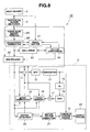
- FIG. 9 is a flowchart showing operations of the image coding apparatus according to the third embodiment.
- FIG. 10 is a block diagram showing a configuration of the image decoding apparatus according to the third embodiment of the present invention.
- FIG. 11 is a flowchart showing operations of image decoding by the image decoding apparatus shown in FIG. 10 .
- interframe coding with motion detection is performed on a particular region with a big movement or a big change with time such as a region including smoke, flare or the like, a predicted error or the amount of interframe coding increases.
- the present embodiment is adapted to detect a particular region with such a property so as not to perform the interframe coding on the particular region as it is.
- a picture of a frame including the particular region detected by the particular region detecting unit 3 is input to the background composing unit 4 .
- the background composing unit 4 removes picture data of the particular region part in a picture other than an intra-picture (abbreviated as I-picture), and generates a background composed picture (or a replaced picture) by replacing the particular region part with a background picture or the like that can further reduce the prediction error.
- I-picture intra-picture
- the background composing unit 4 removes picture data of the particular region part in a picture other than an intra-picture (abbreviated as I-picture), and generates a background composed picture (or a replaced picture) by replacing the particular region part with a background picture or the like that can further reduce the prediction error.
- the I-picture is a picture (frame) on which coding is performed in a frame.
- the picture other than the I-picture, i.e., the picture of inter-picture is subjected to the interframe coding.
- the background composed picture output from the background composing unit 4 is divided into blocks made of the predetermined number of pixels (Macro Block or the like) and input into a picture coding unit 5 .
- the picture coding unit 5 codes each block of the input background composed pictures and generates an output picture 22 .
- the picture coding unit 5 corresponds to a picture coding apparatus that has been generally used.
- the background composing unit 4 generates information on the particular region part for a frame of the I-picture (the information is used in decoding an image), but outputs the blocks divided from the input picture to the picture coding unit 5 .
- the particular region detecting unit 3 has a hue detecting circuit 6 configured to detect whether or not the input picture 2 is a region corresponding to a particular region whose hue matches that of smoke or the like, a first frame buffer 7 configured to store a frame including the region detected by the hue detecting circuit 6 , and motion/shift amount detecting circuit 8 configured to detect motion or the amount of shift between pictures from a picture between frames.
- a hue detecting circuit 6 configured to detect whether or not the input picture 2 is a region corresponding to a particular region whose hue matches that of smoke or the like
- a first frame buffer 7 configured to store a frame including the region detected by the hue detecting circuit 6
- motion/shift amount detecting circuit 8 configured to detect motion or the amount of shift between pictures from a picture between frames.
- the color detecting circuit 6 resolves a color picture, which makes an input picture, into R, G, B components, for example. Then, the color detecting circuit 6 detects whether or not the separated RGB picture components are within a hue range whose properties include smoke or the like by comparing the components with the threshold of the hue (or hue information).
- the information on the hue detected by the hue-detecting circuit 6 can be set by a user from a detection hue setting circuit 23 .
- the detection hue setting circuit 23 may be configured for a user to set by inputting from a keyboard or the like particular hue information corresponding to each hue of smoke, flare or the like to be detected.
- the hue detecting circuit 6 performs hue detection by using at least two or more pieces of particular hue information corresponding to hues of smoke and flare.
- the color detecting circuit 6 may have a function of setting such particular hue information to be detected instead of having the detection hue setting circuit 23 outside.
- the hue information may be hue information including a threshold.
- a threshold taking account of an allowable range set from the standard hue as well as information on standard hue corresponding to each of smoke or flare to be detected For example, as particular hue information, a threshold taking account of an allowable range set from the standard hue as well as information on standard hue corresponding to each of smoke or flare to be detected.
- the color detecting circuit 6 compares a hue component of a frame with the threshold, if it is determined that it is a candidate region with possibility of a particular region within a hue range included in a particular picture part such as smoke, (the picture of) the frame is stored in the first frame buffer 7 and the hue detecting circuit 6 performs the same detection on the next frame.
- the motion/shift amount detecting circuit 8 detects (determines) whether or not the amount of motion or the amount of shift between both candidate regions exceeds the threshold by calculating the amount of motion due to the amount of shift between center positions of corresponding both candidate regions or the sum of two squares of differences of corresponding both pixel values (integrated value of squares) or the like, for example for the both candidate regions determined to match within the threshold by the hue detection between the adjacent frames.
- the motion/shift amount detecting circuit 8 has a threshold setting circuit 8 a for a user to set the threshold.
- the motion/shift amount detecting circuit 8 detects (determines) whether or not the amount of motion or the amount of shift between the both candidate regions exceeds the threshold to determine whether or not the candidate regions are particular regions with the predicted error in the interframe coding as a main property of a particular picture such as smoke, flare or the like increased (therefore, the amount of coding increased).
- the motion/shift amount detecting circuit 8 may also be configured to determine whether or not the candidate regions are particular regions corresponding to a particular picture based on whether or not the value of motion vector exceeds the threshold by detecting the value of motion vector between the both candidate regions instead of calculating the sum of squares.
- next background composing unit 4 replaces the particular region part on which such determination is performed with a background picture or the like other than the particular region.
- the particular region detecting unit 3 also has a method for examining the density to enhance detection accuracy on whether or not it is a particular region as well as the hue detection and the motion/shift amount detection. Specifically, the particular region detecting unit 3 can determine whether or not it is a particular region included in a particular picture part such as smoke by obtaining a variance matrix on a brightness value and a color difference for a certain block and counting the number of components within the threshold.
- the background composing unit 4 has a particular region removing and background generating circuit 9 configured to remove a particular region in a picture that comes through the particular region detecting unit 3 , and a second frame buffer 10 configured to store a frame picture part left after a particular region is removed by the particular region removing and background generating circuit 9 .
- the particular region removing and background generating circuit 9 generates a background composed picture by reading from the second frame buffer 10 the frame picture part left after the particular region is removed and replacing the particular region part with a background picture or the like, divides the background composed picture into a plurality of blocks, and outputs each block (described as a background composition 9 a in FIG. 1 ) to the picture coding unit 5 .
- the background composing unit 4 divides the I-picture for which no interframe coding is performed, i.e., on which no motion vector detection is performed (referred to as I-picture), into a plurality of blocks and outputs each block to the picture coding unit 5 without replacing the particular region part in the input picture 2 with the background picture or the like.
- the particular region removing and background generating circuit 9 detects a particular region part, it outputs information on the region part to the picture coding unit 5 . Then, the output picture 22 coded by the picture coding unit 5 includes the information. When a picture in a frame other than the I-picture is decoded from the output picture 22 , the information is used for generating a picture (specifically, a simulation picture in the second embodiment to be described later) corresponding to an original picture of the particular region part.
- the block may be adopted as a block of a background picture after subjected to motion compensation.
- the block including the particular region may be embedded with an average hue of the particular region instead of being embedded with the above-mentioned background picture. That is, in a case where the particular region is smoke, for example, a processing in which the particular region is embedded with a white block as an average hue value of smoke may be applied. That is, the particular region may be replaced with a predetermined picture such as a background picture, a replaced picture or the like.
- a block including a particular region is replaced with a white block or the like as mentioned above, it may be replaced with a bock in which values for all the pixels forming the block are the same.
- a block B′ in the other frame ( 2 ) is also totally covered with smoke like a block B
- a frame including a background instead of smoke is searched for from several frames before and after the frame as mentioned above. If background blocks in the frame have motion vectors, motion compensation is performed.
- the picture coding unit 5 performs picture coding by usual interframe coding on a background composed picture in which a particular region part is replaced with a background picture or the like, instead of detecting a motion vector for an original particular picture part with smoke or the like on a block of such a frame.
- the present embodiment can avoid an incidence where the amount of predicted error difference in the case where an original picture including smoke or the like are subjected to the interframe coding increases to lead the bigger amount of interframe coding.
- the picture coding unit 5 includes a subtractor 11 configured to perform subtraction on a block of the input background composed picture, a DCT circuit 12 configured to perform discrete cosine transform (abbreviated as DCT) on the output signal from the subtractor 11 , and a quantizing circuit 13 configured to quantize the output signal from the DCT circuit 12 and output the quantized signal.
- DCT discrete cosine transform
- the picture coding unit 5 includes a variable-length coding circuit 14 for separating the DCT coefficient or the motion vector to be described later for the input block into variable-length coded packets and outputting the output picture of bit stream signals.
- the picture coding unit 5 includes an inverse quantizing circuit (abbreviated as IQ in FIG. 1 ) 15 configured to perform inverse quantization on the DCT coefficient output from the quantizing circuit 13 , and an inverse DCT circuit (abbreviated as IDCT in FIG. 1 ) 16 configured to further perform an inverse discrete cosine transform on the inverse-quantized DCT coefficient.
- IQ inverse quantizing circuit
- IDCT inverse DCT circuit
- the picture coding unit 5 includes an adder 17 configured to add an inverse discrete cosine transformed picture, a frame memory 18 configured to store output from the adder 17 , and a motion compensating circuit (or a predicted picture creating circuit) 19 in which the picture stored in the frame memory 18 is input and configured to create a predicted picture subjected to motion compensation.
- the background composed picture is also input into the frame memory 18 .
- the picture coding unit 5 includes a motion detecting circuit 20 configured to perform motion detection by using (blocks of) the background composed picture to be input and a picture stored in the frame memory 18 as a reference picture, and a motion vector predicting circuit 21 configured to predict a motion vector, which is a signal indicating motion toward a block to be output, in response to input of the motion vector of a block to be output from the motion detecting circuit 20 .
- the picture coding unit 5 When the picture to be input in the picture coding unit 5 with such configuration is the I-picture, the picture coding unit 5 only performs the intra-coding (intra-frame coding) on the I-picture. After the intra-coding, the intra-coded output picture 22 is output from the variable-length coding unit 14 .
- the picture coding unit 5 performs the interframe coding on a (inter-)frame other than the I-picture.
- the picture coding unit 5 can perform the interframe coding without making big predicted error.
- each particular region including smoke or the like is replaced with a predetermined picture such as a background picture or the like which can reduce the predicted error in each frame other than the I-picture in the motion picture, the interframe coding can be performed with the small amount of data.
- FIG. 3 Outlined operations of the image coding apparatus 1 according to the present embodiment is shown in FIG. 3 .
- the input picture 2 is input into the image coding apparatus 1 , and the particular region detecting unit 3 detects a particular region from the input picture 2 at step S 1 .
- the particular region detecting unit 3 determines whether or not the input picture 2 is the I-picture (i.e., determines whether or not the input picture 2 is to be coded as the I-picture), for example, at the next step S 2 . Then, if the input picture 2 is the I-picture, the I-picture is sent to the picture coding unit 5 where the picture is subjected to the intra-coding as the I-picture at the next step S 3 .
- step S 4 it is determined whether or not the input picture 2 is the I-picture at step S 4 . If the input picture 2 is the I-picture, the operation proceeds to step S 3 , where the intra-coding is performed on the I-picture.
- step S 2 If it is determined that the input picture 2 is not the I-picture at step S 2 , the operation proceeds to step S 5 , where the particular region removing and background composing unit 4 generates a background composed picture by removing the particular region and replacing it with a background picture. Then at the next step S 6 , the picture coding unit 5 performs the interframe coding on a background composed picture other than the I-picture.
- the interframe coding is also performed at step S 6 .
- the present embodiment operating in such a manner causes the particular region detecting unit 3 to detect whether or not the particular picture 2 includes a particular region with big amount of motion or shift such as a region including smoke or the like and with the increased predicted error, and if such a particular region is not detected, it performs usual coding processing.
- the interframe coding is performed by replacing the particular region with a background picture or the like for a frame other than the I-picture.
- the present embodiment can perform coding with a small amount of coding on an image including a particular region such as smoke with a big amount of motion or big amount of shift.
- FIG. 4 shows a configuration of an image decoding apparatus 31 according to the second embodiment of the present invention.
- the image decoding apparatus 31 performs decoding processing in response to input of a stream signal of the output picture 22 coded by the image coding apparatus 1 according to the first embodiment.
- the image decoding apparatus 31 decodes (reproduces) a particular region in a frame other than the I-picture by using picture information of the particular region covered with smoke or the like in the frame of the first I-picture and information on the particular region.
- the image decoding apparatus 31 includes a second image-decoding unit 33 configured to perform the image decoding on the particular region in a first image-decoding unit 32 configured to perform usual image decoding.
- the stream signal is input into the variable-length decoding circuit 34 forming the first image-decoding unit 32 .
- the coded stream signal in the frame of the I-picture is input into the variable-length decoding circuit 34 , where the variable-length code in the stream signal is returned to a fixed-length code and output to an inverse quantizing circuit 35 .
- variable-length decoding circuit 34 returns the variable-length code to the fixed-length code and outputs it to the inverse quantizing circuit 35 .
- the variable-length decoding circuit 34 also extracts the data part of the coded motion vector in the stream signal and outputs it to a motion vector reconfiguring circuit 36 .
- the motion vector reconfiguring circuit 36 calculates from the input coded motion vector the position information of the motion vector to be referred to in the motion compensation processing. Then, the motion vector reconfiguring circuit 36 sends the calculated position information of the motion vector to a motion compensating circuit 37 .
- the motion compensation circuit 37 generates a motion compensated predicted picture by using the position information of the motion vector.
- the inverse quantizing circuit 35 generates a reproduced DCT coefficient value of the predicted remainder from the fixed-length code and outputs it to an inverse DCT circuit 38 .
- the inverse DCT circuit converts for example, eight by eight coefficients into a reproduced predicted remainder picture and outputs it to an adder 39 .
- the adder 39 adds the predicted picture to the reproduced predicted remainder picture to generate the reproduced picture. In the case of the I-picture, it generates the reproduced picture without performing motion compensation.
- the second image-decoding unit 33 outputs the predicted picture output from the motion compensating circuit 37 to the adder 39 .
- the second image-decoding unit 33 outputs the predicted particular picture generated at the second image-decoding unit 33 to the adder 39 and embeds the predicted particular picture to the particular region so as to generate the reproduced picture in which the particular region is replaced with the predicted particular picture.
- the reproduced picture is output from an output terminal as an output picture, and sent to the frame memory 40 to be stored therein as a reference picture in motion compensation.
- the picture stored in the frame memory 40 is output to the motion compensating circuit 37 , where motion compensation is performed based on the position information of the motion vector obtained from the motion vector reconfiguring circuit 36 by using the picture stored in the frame memory 40 as the reference picture and generates the predicted picture.
- the obtained predicted picture is output to the adder 39 to be used in generating of the reproduced picture of the next frame.
- the second image-decoding unit 33 performs generation of a reproduced picture by generating a predicted picture corresponding to a particular region part in the frame other than the I-picture (hereinafter, refereed to as a predicted particular picture) by using the particular picture part (particular region) such as a part covered with smoke or the like in the first I-picture stored in the frame memory 40 , and replacing the particular region part with the predicted particular picture.
- a predicted particular picture a predicted picture corresponding to a particular region part in the frame other than the I-picture
- the second image-decoding unit 33 includes a predicted particular picture generating circuit 41 configured to generate a predicted particular picture corresponding to smoke or the like that makes an original picture by using the first I-picture until the next I-picture appears, and a particular picture composing circuit 42 configured to decode the predicted particular picture generated by the predicted particular picture generating circuit 41 as a picture in the particular region (particular picture) by performing such processing as embedding the predicted particular picture into a particular region in the frame other than the I-picture.
- a predicted particular picture generating circuit 41 configured to generate a predicted particular picture corresponding to smoke or the like that makes an original picture by using the first I-picture until the next I-picture appears
- a particular picture composing circuit 42 configured to decode the predicted particular picture generated by the predicted particular picture generating circuit 41 as a picture in the particular region (particular picture) by performing such processing as embedding the predicted particular picture into a particular region in the frame other than the I-picture.
- the predicted particular picture generating circuit 41 has a simulation picture generating circuit 41 a configured to generate a simulation picture by simulation as a predicted particular picture in the present embodiment.
- the Navier-Stokes equation as shown below is used in the present embodiment.
- the procedure up to generate a predicted particular picture corresponding to the original picture in the particular region in the frame other than the I-picture will be outlined below.
- the processing of generating a particular picture by embedding a predicted particular picture into the particular region may be collectively performed at the end.
- the method of performing the processing at the end will be described below.
- the particular region corresponding to the original particular picture part such as a part covered with smoke or the like is replaced with another picture (also referred to as a predetermined picture) in the frame other than the I-picture. Therefore, information on motion of the original picture is not included in the decoded information.
- the motion of the original picture part such as removed smoke or the like is made the predicted particular picture by the simulation picture generated by simulation.
- the smoke is considered as a fluid and the two-dimensional Navier-Stokes equation [Formula 1] that describes behavior of the fluid is adopted in the present embodiment.
- the expression (1-1) in the Formula 1 is the two-dimensional Navier-Stokes equation, to which a condition of no smoke gathered is imposed by the expression (1-2).
- w is a velocity vector
- ⁇ is a coefficient of viscosity
- p is a pressure
- f is an external force.
- the Navier-Stokes equation is a nonlinear partial differential equation, and it is difficult to specifically obtain a general solution with the equation.
- the Navier-Stokes equation is made into a difference equation by being discretized in the time direction and integrated to obtain the solution.
- the formula 2 made in the difference equation is shown as (3-2) and (3-3) in the formula 3.
- the expression (3-1) represents a pressure tuple in the expression (3-2), which represents the x component of a velocity vector, and the expression (3-3), which represents the y component.
- initial conditions are set as shown in FIG. 5 , for example.
- FIG. 5 shows in the upper parts frames (actually coded frames) input into the image-decoding apparatus 31 in order, and in the lower part, predicted particular pictures of smoke generated by simulation.
- a part of the predicted particular picture is generated and shown as corresponding with the upper part frame ( 1 ).
- the left-most frame in FIG. 5 is the first I-picture frame.
- the initial conditions are set to the smoke picture part of the frame.
- the initial conditions include four conditions, that is, a velocity vector, a pressure, an external vector and a coefficient of viscosity for each particle of smoke.
- the coefficient of viscosity is constant through the entire frames.
- appropriate initial conditions are given to each particle of smoke in the first I-picture frame ( 1 ).
- FIG. 5 shows a case where the velocity vectors u 1x , v 1y and initial values of the pressure pu 1x O , v 1y O , p O are set.
- the predicted particular pictures of smoke in the frame (n) corresponding to the next I-picture frame (n) are to be chronologically generated in an order of a predicted particular picture corresponding to the next frame ( 2 ), then a predicted particular picture corresponding to the next frame ( 3 ) and so on.
- the velocity vectors u 1x , v 1y changes like u 2x , v 2y , U nx , v ny in the predicted particular pictures in the frame ( 2 ) and in the predicted particular pictures in the frame (n) corresponding to the frame (n) of the I-picture, respectively.
- the predicted particular picture of smoke (or a simulation picture) is generated to the frame (n) shown in the lower part of the right-most of FIG. 5 , the predicted particular picture of smoke is compared with the actual smoke in the actual I-picture frame (n) shown above.
- the comparison is specifically performed in a manner of obtaining the sum of squares of the absolute values of differences of the corresponding pixel values in the picture region of the smoke.
- the pixel values are a brightness value and a color difference value. It is possible to compare for only the brightness value or for both of the brightness value and the color difference value.
- sets of predicted particular pictures are generated for smoke by changing the initial conditions.
- the initial conditions at the moment when the sum of squares of absolute values of the differences of pixel values from the picture region of smoke of the next I-picture is the smallest is selected as the optimal initial conditions of the original I-picture.
- the optimal external force may be selected by perturbing the external force for each particle of each frame.
- a reproduced picture whose particular region is decoded with a particular picture is generated by embedding each of the chronologically generated predicted particular pictures in a predetermined region in a frame that has the closest relationship with each of the predicted particular picture.
- FIG. 6 outlines operations of the image-decoding method by the image-decoding apparatus 31 according to the present embodiment.
- variable-length decoding circuit 34 determines whether or not the input stream signal (coded picture) is the I-picture. If it is the I-picture, the intra-decoding (intra-frame decoding) is performed on it by the first image-decoding apparatus 32 , as shown in step S 12 .
- the decoded I-picture is stored in the frame memory 40 .
- the second image-decoding apparatus 33 generates the predicted particular picture (simulation picture) corresponding to the original picture of the particular region other than the I-picture by using the pictures in the particular region as shown at step 13 .
- a CPU for example, which forms the simulation picture generating circuit 41 a in the predicted particular picture generating circuit 41 , performs the above-mentioned simulation until the next I-picture is reached.
- step S 24 the CPU determines whether or not the compared result is at the threshold or less. If the result is not the threshold or less, the CPU changes the initial conditions set at step S 25 and returns to step S 22 .
- step S 24 If the compared result is the threshold or less at the determination processing at step S 24 , the operation proceeds to step S 26 .
- the present embodiment can generate the original picture of smoke or the like even in the (inter) frame other than the I-picture from the picture coding signal as a stream signal with the small amount of coding.
- decoding can be performed from an image (coded) with small amount of coding.
- the present embodiment has an effect of reducing the transmission quantity of coded image information to be transmitted from the image coding apparatus side.
- the original picture of the particular region may be used in generating the simulation picture.
- a particular picture as a picture that can be sufficiently approximated to the original picture may be used in generating a simulation picture.
- the second embodiment is applied with the processing for performing replacement or the like on the particular region part in the frame to be subjected to the interframe coding with the simulation picture generated from the particular picture of the I-picture by simulation when image decoding is performed on the coded picture.
- the simulation picture is generated by simulation when coding is performed.
- the simulation picture is compared with an actual particular picture such as smoke (original picture) when the coding is performed, and the information for generating the simulation picture and the actual particular picture are coded according to the compared result.
- the particular region removing circuit 9 A removes the particular region detected by the particular region detecting unit 3 and outputs it to a background generating circuit 9 B.
- the background generating circuit 9 B removes the particular region from the input picture 2 , replaces the particular region with a picture such as a background picture or the like, generates the background composed picture and outputs it to the frame buffer 51 , and also outputs it to the simulating circuit 53 .
- the input picture 2 is also input into the frame buffer 51 . Then, the frame buffer 51 outputs the input picture 2 of the particular region part, which is the input picture with the region other than the particular region replaced with the background picture or the like subtracted, into the picture comparing circuit 54 .
- the particular region removing circuit 9 A outputs the input picture 2 to the simulating circuit 53 and a multiplexer 52 through the background generating circuit 9 B without removing the particular region from the input picture 2 .
- the information on the particular region is also input into the simulating circuit 53 .
- the simulating circuit 53 performs simulation on the picture part such as the part covered with smoke in the particular region from the I-picture frame, generates the simulation picture corresponding to the particular region in each frame other than the I-picture, and outputs it to a picture comparing circuit 54 .
- the simulating circuit 53 codes the information for generating the simulation picture (the initial conditions and the like described in the second embodiment) and outputs it to the other side of input terminal of the multiplexer 52 .
- the picture comparing circuit 54 compares the simulation picture output from the simulating circuit 53 with the actual particular picture part such as the part covered with smoke or the like output from the frame buffer 51 , and controls switching (selection) of the multiplexer 52 according to the compared result.
- the picture comparing circuit 54 performs picture comparison whether or not the simulation picture is the picture that can approximate the actual particular picture (original picture) by comparing the threshold with the sum of squares of differences of each pixel value and corresponding pixel value between the simulation picture and the corresponding particular picture part to see if the sum exceeds the threshold or not.
- the compared result showing that the sum exceeds the threshold means that the simulation picture is not so much approximated as to allow the original picture.
- the compared result showing that the sum is within the threshold means that the simulation picture is so much approximated as to allow the original picture.
- the picture comparing circuit 54 may return the result to the simulating circuit 53 to cause simulation to be performed under further different initial conditions.
- the picture coding unit 5 performs usual picture coding on the input picture 2 that actually includes smoke or the like. In contrast, if the gap is the threshold or less, the picture coding unit 5 performs coding on the information for generating the background composed picture whose particular region is replaced and the simulation picture.
- the picture part in which the particular region is replaced with the picture such as the background picture to be described later, is replaced with the simulation picture when the image decoding (picture decoding) is performed at the image decoding apparatus side, the picture part may be set to a particular picture with the small amount of coding, for example with a predetermined amount of coding Qe or less, as a picture (of the background picture) to replace the particular region.
- the input picture 2 is input into the subtractor 11 , the frame memory 18 , the motion compensating circuit 19 , and the motion detecting circuit 20 all included in the picture coding unit 5 .
- the picture coding unit 5 performs usual picture coding.
- the output signal from the multiplexer 52 is input into the subtractor 11 , the frame memory 18 , the motion compensating circuit 19 , and the motion detecting circuit 20 in the picture coding unit 5 .
- the picture coding unit 5 shown in FIG. 8 has been described in FIG. 1 , so that the description thereof is omitted here.
- the image coding apparatus 1 B performs, for example, the operation as shown in FIG. 9 .
- the particular region detecting unit 3 detects whether or not the input picture 2 includes the particular picture such as a picture covered with smoke or the like.
- step S 37 the input picture 2 is coded in the usual method. That is, if no particular region is detected, coding is performed by the picture coding unit 5 as in the existing method.
- the operation proceeds to step S 32 . If it is other than the I-picture, the particular region removing circuit 51 removes the particular region from the input picture 2 , and the background generating circuit 9 B generates the background composed picture by inserting a background picture or the like there. For the I-picture, the frame and the information on the particular region in such a case are input in the simulating circuit 53 .
- the simulating circuit 53 sets the initial conditions to the picture in the particular region in the first I-picture, and sequentially generates the simulation pictures corresponding to the respective frames when the next I-picture is reached as described with reference to the second embodiment.
- the picture comparing circuit 54 calculates the sum of squares of differences between the pixel value for example in Macro Block of the particular region and the pixel value in a block corresponding to the Macro Block.
- the background picture part in the frame with the particular region removed is coded by the picture coding unit 5 as the existing method.
- the information for generating the simulation picture is coded for the particular region part by the picture coding unit 5 .
- the image coding apparatus 1 B can determine whether or not the simulation picture generated as the original picture of the particular region is simulated appropriately represents the original picture by comparing the picture with the original picture (compared result can be obtained).
- the compared result can be obtained for each frame (for a short time interval), for example. Therefore, that facilitates the simulation more appropriately.
- the image decoding at the side of the image decoding apparatus 31 B to be described below can be performed with less processing.
- FIG. 10 shows a configuration of the image decoding apparatus 31 B corresponding to the image coding apparatus 1 B according to the third embodiment.
- the multiplexer 59 usually selects to input the predicted picture output from the motion compensating circuit 37 into the adder 39 .
- the multiplexer 59 detects whether or not the output signal from the variable-length decoding circuit 34 includes the information for generating the simulation picture. If the information is included, the multiplexer 59 switches to input the output from the second image decoding unit 33 B to the adder 39 .
- the particular picture composing circuit 42 and the adder 39 perform composing processing on the simulation picture such as to embed the picture into the particular region part to generate the reproduced picture.
- the predicted picture from the motion compensating circuit 37 is input for the block part, in which the simulation picture and the background picture around the simulation picture are coexistent, in the particular picture composing circuit 42 , so that the particular picture composing circuit 42 composes both of the pictures.
- FIG. 11 is a flowchart of outlined operations of an image decoding method by the image decoding apparatus 31 B shown in FIG. 10 .
- FIG. 11 is same as FIG. 6 except for the processing after step S 13 . Only those different from FIG. 6 will be described.
- the apparatus If it is determined that the picture is not the I-picture at step S 11 , the apparatus generates the picture decoded by the usual interframe decoding as shown at step S 14 ′. In such a case, both the picture with the particular region replaced and the coded picture with the particular region not replaced are included.
- step S 14 ′ is subjected to determination on whether or not it is the particular frame at step S 15 ′. If it is determined that it is not the particular frame, the operation proceeds to step S 116 , where the picture generated at step S 14 ′ is output as a reproduced picture.
- the processing at step S 16 corresponds to the processing to generate the reproduced picture by adding the predicted picture from the motion compensating circuit 37 passed through the multiplexer 59 added at the adder 39 in FIG. 10 .
- the image decoding apparatus 31 B can effectively generate the reproduced picture decoded with a small amount of processing by using the (previously calculated) information for generating the original picture of the particular region by simulation, as the information is added.
- the formula 2 is simplified to the two-dimensional equation as an example of generating a simulation picture by simulation, the formula 2 may be treated as the three dimensional equation so that the result is projected on the two-dimensional plane.
- the simulation may be applied to flare or the other particular pictures. For example, such simulation using the Monte Carlo method may be used.
Abstract
Description
[Formula 1]
(∂/∂t+(w·∇))w=ν·∇ 2 w−∇p−f(t,x,y) (1-1)
∇w=0 (1-2)
where, ∇2=∂2/∂x2+∂2/∂y2, x=w(u, v)
[Formula 2]
(∂/∂t+u∂/∂x+v∂/∂y)u=ν·∇ 2 u−∂p/∂x−f x(t,x) (2-1)
(∂/∂t+u∂/∂x+v∂/∂y)v=ν·∇ 2 v−∂p/∂y−f y(t,y) (2-2)
[Formula 3]
Pressure tuple:
u=p/4+dU x 2 +dU y 2+2·dU y /dU x−(dU x +dV y)+f(t,x,y)/(Δx·Δy) (3-1)
x component:
u t+1 =u t +[v·(r(u)−4u)−dP x −u·dU x −v·dU y +f x(t,x)]·Δt (3-2)
y component:
v t+1 =v t +[v·(r(v)−4v)−dP y −u·dV x −v·dU y +f y(t,y)]·Δt (3-3)
where, r(u)=u(x+Δx, y)+u(x−Δx, y)+u(x, y+Δy)+u(x, y−Δy), dUx=(ui+1−ui−1)/(2Δx), dUy=(uj+1−uj−1)/(2Δy), Δx=Δy=1, Δt is a time of a frame interval and the like.
Claims (8)
Applications Claiming Priority (2)
| Application Number | Priority Date | Filing Date | Title |
|---|---|---|---|
| JP2006271167A JP4939890B2 (en) | 2006-10-02 | 2006-10-02 | Video encoding apparatus, video decoding apparatus, and video decoding method |
| JP2006-271167 | 2006-10-02 |
Publications (2)
| Publication Number | Publication Date |
|---|---|
| US20080080779A1 US20080080779A1 (en) | 2008-04-03 |
| US8320691B2 true US8320691B2 (en) | 2012-11-27 |
Family
ID=39261277
Family Applications (1)
| Application Number | Title | Priority Date | Filing Date |
|---|---|---|---|
| US11/860,823 Expired - Fee Related US8320691B2 (en) | 2006-10-02 | 2007-09-25 | Image coding apparatus, image decoding apparatus, and image decoding method |
Country Status (2)
| Country | Link |
|---|---|
| US (1) | US8320691B2 (en) |
| JP (1) | JP4939890B2 (en) |
Cited By (1)
| Publication number | Priority date | Publication date | Assignee | Title |
|---|---|---|---|---|
| US9940689B2 (en) | 2015-11-02 | 2018-04-10 | Nvidia Corporation | Latency-resistant sparse simulation technique, system and method |
Families Citing this family (7)
| Publication number | Priority date | Publication date | Assignee | Title |
|---|---|---|---|---|
| KR100987786B1 (en) | 2008-07-23 | 2010-10-13 | (주)에이치엠씨 | Fire detecting system using smoke sensing |
| US8958478B2 (en) * | 2010-12-03 | 2015-02-17 | Technische Universitaet Berlin | Method and device for processing pixels contained in a video sequence |
| RU2616441C1 (en) | 2011-11-08 | 2017-04-14 | Кт Корпорейшен | Video signal decoding method |
| KR102039688B1 (en) * | 2013-03-14 | 2019-11-01 | 삼성전자주식회사 | User device and operating method thereof |
| US9876964B2 (en) * | 2014-05-29 | 2018-01-23 | Apple Inc. | Video coding with composition and quality adaptation based on depth derivations |
| JP2016066922A (en) * | 2014-09-25 | 2016-04-28 | ソニー株式会社 | Signal processor, imaging apparatus, and signal processing method in them |
| JP7247825B2 (en) | 2018-12-17 | 2023-03-29 | Agc株式会社 | Glass composition, composite powder material, composite powder material paste, printer head for laser printer, and thermal printer head |
Citations (22)
| Publication number | Priority date | Publication date | Assignee | Title |
|---|---|---|---|---|
| JPS6212286A (en) | 1985-07-09 | 1987-01-21 | Nec Corp | System and device for encoding moving image signal |
| JPS6212287A (en) | 1985-07-09 | 1987-01-21 | Nec Corp | Adaptive predictive encoding device for moving image signal |
| US4689671A (en) * | 1985-06-27 | 1987-08-25 | Nec Corporation | Coding apparatus for moving object image |
| US4941193A (en) * | 1987-10-02 | 1990-07-10 | Iterated Systems, Inc. | Methods and apparatus for image compression by iterated function system |
| US5177608A (en) * | 1990-09-20 | 1993-01-05 | Nec Corporation | Method and apparatus for coding moving image signal |
| JPH07264597A (en) | 1994-03-18 | 1995-10-13 | Nippon Telegr & Teleph Corp <Ntt> | Compensating method for motion |
| US5592228A (en) | 1993-03-04 | 1997-01-07 | Kabushiki Kaisha Toshiba | Video encoder using global motion estimation and polygonal patch motion estimation |
| US5751362A (en) | 1995-04-29 | 1998-05-12 | Daewoo Electronics, Co., Ltd. | Apparatus for encoding a video signal using feature point based motion estimation |
| JPH11308623A (en) | 1998-04-24 | 1999-11-05 | Sony Corp | Image processor |
| US6052414A (en) * | 1994-03-30 | 2000-04-18 | Samsung Electronics, Co. Ltd. | Moving picture coding method and apparatus for low bit rate systems using dynamic motion estimation |
| US6301301B1 (en) * | 1997-08-05 | 2001-10-09 | Mitsubishi Denki Kabushiki Kaisha | Apparatus and method for coding and decoding a moving image |
| US6335985B1 (en) * | 1998-01-07 | 2002-01-01 | Kabushiki Kaisha Toshiba | Object extraction apparatus |
| JP2003288603A (en) | 2002-03-28 | 2003-10-10 | Nippon Telegr & Teleph Corp <Ntt> | Method, device, program, and recording medium for image scene prediction |
| US6774908B2 (en) * | 2000-10-03 | 2004-08-10 | Creative Frontier Inc. | System and method for tracking an object in a video and linking information thereto |
| JP2004334694A (en) | 2003-05-09 | 2004-11-25 | Nippon Telegr & Teleph Corp <Ntt> | Image generation method, device, program and record medium recording the program |
| US20050232606A1 (en) * | 2004-03-24 | 2005-10-20 | Tatsuya Hosoda | Video processing device |
| US20070147690A1 (en) * | 2005-12-27 | 2007-06-28 | Kabushiki Kaisha Toshiba | Video coding device, video decoding device and video encoding method |
| US7292633B2 (en) * | 1999-09-02 | 2007-11-06 | Kabushiki Kaisha Toshiba | Method for detecting a moving object in motion video and apparatus therefor |
| US20080123747A1 (en) * | 2006-11-28 | 2008-05-29 | Samsung Electronics Co., Ltd. | Method and apparatus for encoding and decoding video images |
| US20080317289A1 (en) * | 2006-08-08 | 2008-12-25 | Hideki Oyaizu | Image Processing Apparatus and Method, Program, and Medium Storing the Program Thereon |
| US20090002517A1 (en) * | 2006-01-10 | 2009-01-01 | Matsushita Electric Industrial Co., Ltd. | Color Correction Device, Color Correction Method, Dynamic Camera Color Correction Device, and Video Search Device Using the Same |
| US7612909B2 (en) * | 2001-06-20 | 2009-11-03 | Sony Corporation | Image processing apparatus and method, and image-capturing apparatus based on the difference between a signal detected by a sensor and the real world |
-
2006
- 2006-10-02 JP JP2006271167A patent/JP4939890B2/en not_active Expired - Fee Related
-
2007
- 2007-09-25 US US11/860,823 patent/US8320691B2/en not_active Expired - Fee Related
Patent Citations (22)
| Publication number | Priority date | Publication date | Assignee | Title |
|---|---|---|---|---|
| US4689671A (en) * | 1985-06-27 | 1987-08-25 | Nec Corporation | Coding apparatus for moving object image |
| JPS6212287A (en) | 1985-07-09 | 1987-01-21 | Nec Corp | Adaptive predictive encoding device for moving image signal |
| JPS6212286A (en) | 1985-07-09 | 1987-01-21 | Nec Corp | System and device for encoding moving image signal |
| US4941193A (en) * | 1987-10-02 | 1990-07-10 | Iterated Systems, Inc. | Methods and apparatus for image compression by iterated function system |
| US5177608A (en) * | 1990-09-20 | 1993-01-05 | Nec Corporation | Method and apparatus for coding moving image signal |
| US5592228A (en) | 1993-03-04 | 1997-01-07 | Kabushiki Kaisha Toshiba | Video encoder using global motion estimation and polygonal patch motion estimation |
| JPH07264597A (en) | 1994-03-18 | 1995-10-13 | Nippon Telegr & Teleph Corp <Ntt> | Compensating method for motion |
| US6052414A (en) * | 1994-03-30 | 2000-04-18 | Samsung Electronics, Co. Ltd. | Moving picture coding method and apparatus for low bit rate systems using dynamic motion estimation |
| US5751362A (en) | 1995-04-29 | 1998-05-12 | Daewoo Electronics, Co., Ltd. | Apparatus for encoding a video signal using feature point based motion estimation |
| US6301301B1 (en) * | 1997-08-05 | 2001-10-09 | Mitsubishi Denki Kabushiki Kaisha | Apparatus and method for coding and decoding a moving image |
| US6335985B1 (en) * | 1998-01-07 | 2002-01-01 | Kabushiki Kaisha Toshiba | Object extraction apparatus |
| JPH11308623A (en) | 1998-04-24 | 1999-11-05 | Sony Corp | Image processor |
| US7292633B2 (en) * | 1999-09-02 | 2007-11-06 | Kabushiki Kaisha Toshiba | Method for detecting a moving object in motion video and apparatus therefor |
| US6774908B2 (en) * | 2000-10-03 | 2004-08-10 | Creative Frontier Inc. | System and method for tracking an object in a video and linking information thereto |
| US7612909B2 (en) * | 2001-06-20 | 2009-11-03 | Sony Corporation | Image processing apparatus and method, and image-capturing apparatus based on the difference between a signal detected by a sensor and the real world |
| JP2003288603A (en) | 2002-03-28 | 2003-10-10 | Nippon Telegr & Teleph Corp <Ntt> | Method, device, program, and recording medium for image scene prediction |
| JP2004334694A (en) | 2003-05-09 | 2004-11-25 | Nippon Telegr & Teleph Corp <Ntt> | Image generation method, device, program and record medium recording the program |
| US20050232606A1 (en) * | 2004-03-24 | 2005-10-20 | Tatsuya Hosoda | Video processing device |
| US20070147690A1 (en) * | 2005-12-27 | 2007-06-28 | Kabushiki Kaisha Toshiba | Video coding device, video decoding device and video encoding method |
| US20090002517A1 (en) * | 2006-01-10 | 2009-01-01 | Matsushita Electric Industrial Co., Ltd. | Color Correction Device, Color Correction Method, Dynamic Camera Color Correction Device, and Video Search Device Using the Same |
| US20080317289A1 (en) * | 2006-08-08 | 2008-12-25 | Hideki Oyaizu | Image Processing Apparatus and Method, Program, and Medium Storing the Program Thereon |
| US20080123747A1 (en) * | 2006-11-28 | 2008-05-29 | Samsung Electronics Co., Ltd. | Method and apparatus for encoding and decoding video images |
Non-Patent Citations (7)
| Title |
|---|
| Amoroso, C.; Ardizzone, E.; Morreale, V.; Storniolo, P.; "A new technique for color image segmentation", Proceedings of International Conference on Image Analysis and Processing, 1999, pp. 352-357. * |
| Bertalmio, M.; Bertozzi, A.L.; Sapiro, G.; "Navier-stokes, fluid dynamics, and image and video inpainting", IEEE Computer Society Conference on Computer Vision and Pattern Recognition, 2001. pp. I-355-1-362 vol. 1. * |
| Hepper, D.; "Efficiency analysis and application of uncovered background prediction in a low bit rate image coder", IEEE Transactions on Communications, vol. 38,1990 , pp. 1578-1584. * |
| Japanese Office Action issued Nov. 30, 2010, in Patent Application No. 2006-271167. |
| Kaup, A.; Aach, T.; "Efficient prediction of uncovered background in interframe coding using spatial extrapolation", IEEE International Conference on Acoustics, Speech, and Signal Processing, 1994. ICASSP-94., pp. V/501-V/504 vol. 5. * |
| Mukawa, N.; Kuroda, H.; "Uncovered Background Prediction in Interframe Coding", IEEE Transactions on Communications, vol. 33, 1985 , pp. 1227-1231. * |
| Office Action issued Nov. 8, 2011 in Japan Application No. 2006-271167. |
Cited By (1)
| Publication number | Priority date | Publication date | Assignee | Title |
|---|---|---|---|---|
| US9940689B2 (en) | 2015-11-02 | 2018-04-10 | Nvidia Corporation | Latency-resistant sparse simulation technique, system and method |
Also Published As
| Publication number | Publication date |
|---|---|
| JP2008092301A (en) | 2008-04-17 |
| JP4939890B2 (en) | 2012-05-30 |
| US20080080779A1 (en) | 2008-04-03 |
Similar Documents
| Publication | Publication Date | Title |
|---|---|---|
| US8320691B2 (en) | Image coding apparatus, image decoding apparatus, and image decoding method | |
| AU2016201339B2 (en) | Image predictive encoding device, image predictive encoding method, image predictive encoding program, image predictive decoding device, image predictive decoding method, and image predictive decoding program | |
| KR101633443B1 (en) | Luminance evaluation | |
| US8204136B2 (en) | Image encoding apparatus | |
| TWI692246B (en) | Image prediction decoding method | |
| EP2960855B1 (en) | Method and device for determining a set of modifiable elements in a group of pictures | |
| KR100800772B1 (en) | Apparatus and method for encoding motion vector, and program and medium therefor | |
| JP4197695B2 (en) | Video encoding method, apparatus, and program | |
| KR100378795B1 (en) | Flexible direct mode coding method for b pictures in moving picture | |
| KR20120045132A (en) | Apparatus and method for encoding video | |
| CN1748427A (en) | Predictive encoding of motion vectors including a flag notifying the presence of coded residual motion vector data | |
| JP4415186B2 (en) | Moving picture coding apparatus, moving picture decoding apparatus, codec apparatus, and program | |
| JP2005303738A (en) | Image processing apparatus | |
| JP4978582B2 (en) | Stream creation device | |
| JP3967688B2 (en) | Video data encoding method, video data decoding method, video data encoding device, video data decoding device, video data encoding program, video data decoding program, and recording medium on which these programs are recorded | |
| JP2005122571A (en) | Image processor, image processing method, program and storage medium | |
| KR100521026B1 (en) | Method for protecting private information using special-effects in handset |
Legal Events
| Date | Code | Title | Description |
|---|---|---|---|
| AS | Assignment |
Owner name: KABUSHIKI KAISHA TOSHIBA, JAPAN Free format text: ASSIGNMENT OF ASSIGNORS INTEREST;ASSIGNOR:NAKANISHI, KEIRI;REEL/FRAME:020057/0813 Effective date: 20070927 |
|
| STCF | Information on status: patent grant |
Free format text: PATENTED CASE |
|
| FPAY | Fee payment |
Year of fee payment: 4 |
|
| FEPP | Fee payment procedure |
Free format text: MAINTENANCE FEE REMINDER MAILED (ORIGINAL EVENT CODE: REM.); ENTITY STATUS OF PATENT OWNER: LARGE ENTITY |
|
| LAPS | Lapse for failure to pay maintenance fees |
Free format text: PATENT EXPIRED FOR FAILURE TO PAY MAINTENANCE FEES (ORIGINAL EVENT CODE: EXP.); ENTITY STATUS OF PATENT OWNER: LARGE ENTITY |
|
| STCH | Information on status: patent discontinuation |
Free format text: PATENT EXPIRED DUE TO NONPAYMENT OF MAINTENANCE FEES UNDER 37 CFR 1.362 |
|
| FP | Lapsed due to failure to pay maintenance fee |
Effective date: 20201127 |