US8325798B1 - Adaptive motion estimation cache organization - Google Patents
Adaptive motion estimation cache organization Download PDFInfo
- Publication number
- US8325798B1 US8325798B1 US11/305,457 US30545705A US8325798B1 US 8325798 B1 US8325798 B1 US 8325798B1 US 30545705 A US30545705 A US 30545705A US 8325798 B1 US8325798 B1 US 8325798B1
- Authority
- US
- United States
- Prior art keywords
- cache
- motion estimation
- frame
- data
- search window
- Prior art date
- Legal status (The legal status is an assumption and is not a legal conclusion. Google has not performed a legal analysis and makes no representation as to the accuracy of the status listed.)
- Active, expires
Links
Images


Classifications
-
- H—ELECTRICITY
- H04—ELECTRIC COMMUNICATION TECHNIQUE
- H04N—PICTORIAL COMMUNICATION, e.g. TELEVISION
- H04N19/00—Methods or arrangements for coding, decoding, compressing or decompressing digital video signals
- H04N19/50—Methods or arrangements for coding, decoding, compressing or decompressing digital video signals using predictive coding
- H04N19/503—Methods or arrangements for coding, decoding, compressing or decompressing digital video signals using predictive coding involving temporal prediction
- H04N19/51—Motion estimation or motion compensation
- H04N19/573—Motion compensation with multiple frame prediction using two or more reference frames in a given prediction direction
-
- H—ELECTRICITY
- H04—ELECTRIC COMMUNICATION TECHNIQUE
- H04N—PICTORIAL COMMUNICATION, e.g. TELEVISION
- H04N19/00—Methods or arrangements for coding, decoding, compressing or decompressing digital video signals
- H04N19/42—Methods or arrangements for coding, decoding, compressing or decompressing digital video signals characterised by implementation details or hardware specially adapted for video compression or decompression, e.g. dedicated software implementation
- H04N19/43—Hardware specially adapted for motion estimation or compensation
- H04N19/433—Hardware specially adapted for motion estimation or compensation characterised by techniques for memory access
Definitions
- the invention relates to video data processing systems and methods, and in particular to video coding (encoding/decoding) systems and methods.
- Commonly-used video coding methods are based on MPEG (Moving Pictures Experts Group) standards such as MPEG-2, MPEG-4 (MPEG 4 Part 2) or H.264 (MPEG 4 Part 10).
- MPEG Motion Picture Experts Group
- Such coding methods typically employ three types of frames: I- (intra), P- (predicted), and B- (bidirectional) frames.
- An I-frame is encoded spatially using data only from that frame (intra-coded).
- P- and B-frames are encoded using data from the current frame and/or other frames (inter-coded).
- Inter-encoding involves encoding differences between frames, rather than the full data of each frame, in order to take advantage of the similarity of spatially and/or temporally proximal areas in typical video sequences.
- Some encoding methods also use intra-frame predictions to encode data differentially with respect to prediction data from the same frame.
- Blocks of 16 ⁇ 16 pixels are commonly termed macroblocks. Other block sizes used in encoders using the H.264 standard include 16 ⁇ 8, 8 ⁇ 16, 8 ⁇ 8, 8 ⁇ 4, 4 ⁇ 8, and 4 ⁇ 4 pixels.
- a typical MPEG encoder searches for a corresponding similar block (prediction) in one or more reference frames. If a similar block is found, the MPEG encoder stores residual data representing differences between the current block and the similar block, as well as motion vectors identifying the difference in position between the blocks. The residual data is converted to the frequency domain using a transform such as a discrete cosine transform (DCT). The resulting frequency-domain data is quantized and variable-length (entropy) coded before storage/transmission.
- DCT discrete cosine transform
- entropy variable-length
- Some video sequences may be encoded as a series of complete frames (progressive sampling), or as a sequence of interlaced fields (interlaced sampling).
- An interlaced field includes either the odd-numbered or the even-numbered lines in a frame.
- a video encoder may encode macroblocks in a frame DCT mode, in which each block is frequency-transformed as a whole, or in a field DCT mode, in which the luminance samples from field 1 are placed in the top half of the macroblock and the samples from field 2 are placed in the bottom half of the macroblock before frequency-domain transfer.
- a field motion compensation mode the data of the two fields in a macroblock may be motion-compensated separately; in such a mode, each macroblock has two associated motion compensation vectors—one for each field.
- the type of encoding may be specified for each frame or slice.
- a macroblock-adaptive frame/field (MBAFF) encoding mode the type of encoding (field or frame) is specified at the macroblock level.
- MBAFF encoding data may be encoded using vertically-stacked macroblock pairs, 16 ⁇ 32 pixels each. Each macroblock pair may be encoded in a frame mode, with the two macroblocks in the pair encoded separately, or in a field mode, with the 16 ⁇ 16 field 1 of the macroblock pair and the 16 ⁇ 16 field 2 of the macroblock pair encoded separately.
- Searching for a prediction for a current macroblock is commonly performed in a search window, which is a sub-area of a reference frame.
- a search window may be a horizontal stripe or band vertically centered about the current macroblock position, and may include tens or hundreds of macroblocks. Accessing (reading/writing) prediction data to and from memory may require relatively high memory bandwidths.
- a video data processing method comprises performing an adaptive mapping of a set of prediction data of a reference video frame to a motion estimation cache according to a width of the reference video frame, and accessing the prediction data in the motion estimation cache according to the adaptive mapping.
- a video data processing method comprises performing an adaptive partitioning of a motion estimation cache in a number of partitions determined by a number of reference frames corresponding to a current frame; and accessing prediction data in the motion estimation cache according to the adaptive partitioning.
- a video data processing method comprises adaptively configuring an organization of a motion estimation cache according to a set of properties of a set of reference frames corresponding to a current frame to be coded; and accessing reference frame prediction data in the motion estimation cache according to the organization of the motion estimation cache.
- a video coding apparatus comprises a motion estimation cache; and a motion estimation cache manager connected to the motion estimation cache.
- the motion estimation cache manager is configured to adaptively configure an organization of the motion estimation cache according to a set of properties of a set of reference frames corresponding to a current frame to be coded; and access prediction data in the motion estimation cache according to the organization of the motion estimation cache.
- FIG. 1 illustrates an exemplary current frame and two exemplary corresponding reference frames according to some embodiments of the present invention.
- FIG. 2-A shows a video encoder including a motion estimation cache and cache manager according to some embodiments of the present invention.
- FIG. 2-B shows a video decoder including a motion estimation cache and cache manager according to some embodiments of the present invention.
- FIG. 3-A shows an exemplary partitioning of a motion estimation cache into two or three partitions each corresponding to a reference frame, according to some embodiments of the present invention.
- FIG. 3-B illustrates a relationship between cache locations and frame widths, according to some embodiments of the present invention.
- FIG. 4 shows a motion estimation search window organization including allocation units arranged generally as a rectangle with two truncated corners, according to some embodiments of the present invention.
- FIG. 5-A shows exemplary code mapping an address of a cache allocation unit to the top left corner of a 16 ⁇ 8 rectangle in a reference frame, according to some embodiments of the present invention.
- FIGS. 5-B-C illustrate a mapping of cache allocation units to reference frame locations performed according to the code of FIG. 5-A for non-MBAFF and MBAFF pictures, respectively, according to some embodiments of the present invention.
- FIG. 6 shows exemplary code illustrating an adaptive computation of a motion estimation search range as a function of cache partition size and frame width, according to some embodiments of the present invention.
- FIG. 7 shows an exemplary mapping of reference frame locations to motion estimation cache allocation units for a non-MBAFF frame and a vertical search range spanning an even number of allocation units, according to some embodiments of the present invention.
- FIG. 8 shows an exemplary mapping of reference frame locations to motion estimation cache allocation units for a non-MBAFF frame and a vertical search range spanning an odd number of allocation units, according to some embodiments of the present invention.
- FIG. 9 shows an exemplary mapping of reference frame locations to motion estimation cache allocation units for a MBAFF frame and a vertical search range spanning an even-multiple-of-two number of allocation units, according to some embodiments of the present invention.
- FIG. 10 shows an exemplary mapping of reference frame locations to motion estimation cache allocation units for a MBAFF frame and a vertical search range spanning an odd-multiple-of-two number of allocation units, according to some embodiments of the present invention.
- FIGS. 11-A-B show exemplary code illustrating a mapping of a motion vector to a motion estimation cache allocation unit, according to some embodiments of the present invention.
- FIG. 12 shows an exemplary internal structure of a motion estimation cache and manager according to some embodiments of the present invention.
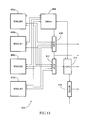
- FIG. 13 shows an exemplary internal structure of a write control logic unit of the cache manager of FIG. 12 , according to some embodiments of the present invention.
- a set of elements includes one or more elements. Any recitation of an element is understood to refer to at least one element. Unless otherwise required, any described method steps need not be necessarily performed in a particular illustrated order. Unless otherwise specified, the term coding encompasses encoding and/or decoding. Accessing data in a cache encompasses reading and/or writing the data. The statement that a cache configuration is performed adaptively means that the configuration is performed in response to potentially-varying characteristics of received video data, and not merely during a design of the cache.
- a first element e.g.
- a data derived from a second element encompasses a first element equal to the second element, as well as a first element generated by processing the second element and optionally other data.
- the term block encompasses macroblocks (16 ⁇ 16 blocks), are well as blocks of other sizes, such as conventional macroblock partitions. Unless otherwise specified, block dimensions (e.g. 16 ⁇ 8) are listed in a (horizontal, vertical) order.
- Making a determination or decision according to a parameter encompasses making the determination or decision according to the parameter and optionally according to other data.
- an indicator of some quantity/data may be the quantity/data itself, or an indicator different from the quantity/data itself.
- any recited encoder or decoder may be implemented using any combination of special-purpose encoding/decoding logic and/or software code running on a programmable processor (e.g. a microcontroller or general-purpose processor).
- the term “cache” encompasses both an overall cache and individual cache partitions of a larger cache.
- a recited motion estimation cache may be a motion estimation cache in an encoder and/or decoder; in an encoder, such a cache may store a motion estimation search window for performing a motion estimation search, while in a decoder such a cache may store prediction data to be used in reconstructing video data.
- Computer readable media encompass storage media such as magnetic, optic, and semiconductor media (e.g. hard drives, optical disks, flash memory, DRAM), as well as communications links such as conductive cables and fiber optic links.
- the present invention provides systems and methods for adaptively configuring a motion estimation cache organization according to properties of a current frame to be encoded/decoded.
- the motion estimation cache organization is configured according to a number of reference frames used to encode/decode the current frame, and/or according to the width (horizontal extent) of the current frame.
- Configuring the cache organization includes altering a mapping between reference frame locations and cache memory addresses.
- Adaptively configuring the cache organization according to frame properties as described below allows optimizing the cache utilization and minimizing the external memory bandwidth used for motion estimation data, particularly for encoders/decoders processing frames having different widths and different numbers of associated reference frames. Different widths may correspond to different display formats, such as standard definition (720 horizontal pixels), VGA (640 horizontal pixels), QVGA (320 pixels), XGA (1024 horizontal pixels), and HDTV (1280 or 1920 horizontal pixels).
- FIG. 1 shows an exemplary frame 20 to be encoded by a video encoder, as well as two exemplary reference frames 22 a - b according to some embodiments of the present invention.
- a reference frame may coincide with the current frame to be encoded.
- Frame 20 includes plurality of macroblocks, including a current macroblock 30 .
- Macroblock 30 includes an exemplary visual feature 32 , which may be part of an object in the image to be encoded. If reference frames 22 a - b are temporally close to frame 20 , corresponding similar visual features 32 a - b are likely to be found at locations within frames 22 a - b that are not too distant from the original position of video feature 32 within macroblock 30 .
- the reference frame macroblocks located in the frame position of macroblock 30 are shown at 30 a - b.
- a search for macroblocks in reference frames 22 a - b that are similar in content to macroblock 30 may be centered about macroblocks 30 a - b.
- An exemplary band-shaped search window 40 a is shown for reference frame 22 a, while an exemplary laterally-bounded search window 40 b is shown for reference 22 b.
- the data of a search window such as search windows 40 a - b is pre-fetched into a cache/buffer, and subsequent search operations are performed on the cached data.
- a search may be performed within a search range (sub-area) within a search window, as illustrated by an exemplary search range 44 a defined within search window 40 a.
- a search range may also coincide with a full extent of a search window.
- FIG. 2-A shows a schematic diagram of a video encoder 52 and an associated off-chip random access memory (RAM) 50 , according to some embodiments of the present invention.
- Encoder 52 includes a memory interface 58 connected to RAM 50 , an encoder controller 62 connected to memory interface 58 , a motion estimation cache unit 60 connected to memory interface 58 and encoder controller 62 , and a motion estimation/compensation unit 64 connected to encoder controller 62 and motion estimation cache unit 60 .
- Encoder 52 may include other units performing operations such as quantization, frequency-domain transform, and variable length encoding. Such units may be connected to the encoder units shown in FIG. 2-A , as illustrated schematically by the connections 68 a - b.
- encoder controller 62 comprises a programmable microcontroller running software that controls a number of configurable motion estimation cache organization parameters described below.
- one or more blocks of encoder 52 may be data-driven hardware cores interconnected as described in U.S. Pat. No. 6,145,073.
- Motion estimation cache unit 60 includes a motion estimation cache and associated cache control logic. The cache control logic controls an adaptive mapping of reference frame data to cache locations, described in detail below.
- Motion estimation/compensation unit 64 receives reference frame data from motion estimation cache unit 60 , and performs a motion estimation search using the received reference frame data.
- FIG. 2-B shows a schematic diagram of a video decoder 52 ′ and an associated RAM 50 , according to some embodiments of the present invention.
- Decoder 52 ′ includes a memory interface 58 ′ connected to RAM 50 , a decoder controller 62 ′ connected to memory interface 58 ′, a motion estimation cache unit 60 ′ connected to memory interface 58 ′ and decoder controller 62 ′, and a motion estimation/compensation unit 64 ′ connected to decoder controller 62 ′ and motion estimation cache unit 60 ′.
- Decoder 52 ′ may include other units performing operations such as inverse quantization, inverse frequency-domain transform, and variable length decoding. Such units may be connected to the decoder units shown in FIG. 2-B , as illustrated schematically by the connections 68 a - b′.
- decoder controller 62 ′ comprises a programmable microcontroller running software that controls a number of configurable motion estimation cache organization parameters described below.
- one or more blocks of encoder 52 may be data-driven hardware cores interconnected as described in U.S. Pat. No. 6,145,073.
- Motion estimation cache unit 60 ′ includes a motion estimation cache and associated cache control logic. The cache control logic controls an adaptive mapping of reference frame data to cache locations, described in detail below.
- Motion estimation/compensation unit 64 ′ receives reference frame data from motion estimation cache unit 60 ′, and uses the retrieved data to reconstruct video data to be displayed.
- the same motion estimation cache and cache manager may be used for both encoding and decoding operations, for example in a coding apparatus capable of both encoding and decoding video data.
- the motion estimation cache is partitioned in a number of cache partitions according to a number of reference frames associated with the current frame to be encoded/decoded.
- FIG. 3-A illustrates an exemplary partitioning of a motion estimation cache 80 into two partitions 82 a - b when a current frame is being encoded/decoded with reference to two reference frames 22 a - b, and into three cache partitions 82 a - c ′ when a current frame is being encoded/decoded with reference to three reference frames 86 a - c.
- the size of each cache partition may be chosen to be 1/N of the motion estimation cache, wherein N is the number of reference frames associated with the current frame.
- different cache partitions may have unequal sizes. For example, a cache partition size for a given reference frame may be chosen according to a temporal distance between the current frame and the reference frame. In some instances, a number of reference frames may exceed a maximum available number of partitions; in such instances, the cache partitions may accommodate only some of the reference frames.
- each cache partition is organized according to a reference frame width.
- a mapping of reference frame locations to cache memory addresses is configured according to a reference frame width as described below.
- FIG. 3-B illustrates an exemplary mapping of lines 90 of a reference frame 22 to corresponding cache address ranges 92 a - c of a cache partition 82 , and an exemplary mapping of lines 90 ′ of a reference frame 22 ′ to corresponding cache address ranges 92 a - d ′.
- Lines 90 have larger widths (larger horizontal pixel numbers) than lines 90 ′.
- Remainder regions 94 , 94 ′ may be used to store additional data as described below.
- the addresses of a motion estimation cache are grouped in multi-pixel allocation units.
- a search window and a search range within the search window may be defined in allocation units.
- An exemplary allocation unit size is 16 ⁇ 8 (horizontal ⁇ vertical) pixels, i.e. half a macroblock, described in detail below.
- an allocation unit may be defined as a macroblock, a macroblock partition, or multiple macroblocks.
- a search window may correspond to a non-rectangular reference frame area.
- a search window reference frame area may be shaped as a quasi-rectangle with truncated upper-left and lower-right corner areas.
- FIG. 4 shows an exemplary truncated-corner quasi-rectangle search window 120 centered about a current macroblock position 124 .
- Search window 120 extends horizontally across an entire reference frame width, and vertically across a part of the reference frame height.
- the reference frame data within search window 120 is grouped in 16 ⁇ 8 allocation units 122 defined in a motion estimation cache.
- Search window 120 includes a rectangular search range 132 .
- Search range 132 defines a subset of search window allocation units within which a motion estimation search is performed for the current macroblock.
- Search range 132 is characterized by a horizontal search range HUnit and a vertical search range VUnit, which may be expressed as numbers of allocation units.
- the horizontal and vertical sizes of search range 132 are 2 ⁇ HUnit+1 and 2 ⁇ VUnit+ 1 , respectively.
- an allocation unit pair storing the data of an upper-left reference frame location 130 is overwritten with the data of a lower-right reference frame location 130 ′.
- Locations 130 , 130 ′ can be thought of as search window advancement regions.
- the following discussion provides a better understanding of an exemplary approach to adaptively configuring a motion estimation cache organization, including adaptively mapping cache allocation units to a reference frame, mapping motion vectors to allocation units, allocating and de-allocating cache units as coding progresses, and computing a search window search range, according to some embodiments of the present invention.
- the exemplary adaptive configuration approach described below allows a full and efficient use of the motion estimation cache for accessing reference frames having different widths and other characteristics. Frames having different widths are stored in the cache at different times. A given video frame sequence typically includes frames having the same width.
- the discussion below will focus on an exemplary cache including 160 K of SRAM partitioned in 1280 allocation units (AU), each of 128 bytes (half a macroblock luma).
- the SRAM may be provided as eight 2560 ⁇ 64 single-port SRAM units.
- Each AU is used as a 16 ⁇ 18 array storing luminance (luma) data.
- the 1280 allocation units are adaptively divided among up to four reference frames. As a skilled artisan will appreciate, other memory size and memory organization parameters may be used in some embodiments of the present invention.
- Cache allocation units are mapped to external RAM addresses and reference frame locations.
- a cache address within a given search window is formed by concatenating an absolute allocation unit number (0-1279) with a line number within the allocation unit to form a 12-bit address, SWAddr[11:0].
- the absolute allocation unit number is equal to the sum of the allocation unit number within a search window and the start offset of the search window.
- FIG. 5-A shows exemplary C-like code suitable for determining a location of the top left corner of a 16 ⁇ 8 block of the reference frame corresponding to an allocation unit of the search window.
- the exemplary code of FIG. 5-A generates horizontal and vertical locations of a given allocation unit within a reference frame for a given absolute allocation unit number (termed VAU in FIG. 5-A ), a search window size, and search window offset.
- FIGS. 5-B and 5 -C illustrate corresponding allocation unit number relationships to reference frame positions for a 44-AU search window and 8 ⁇ 6 (48 AU) non-MBAFF and MBAFF pictures, respectively. As illustrated by FIGS. 5-B-C , the mapping of allocation unit numbers to reference frame locations depends on the frame width and search window size.
- a motion estimation search range also depends on the frame width and/or cache partition size.
- FIG. 6 shows C-like code illustrating an exemplary adaptive computation of a motion estimation search range as a function of cache partition size (SWSize), frame width (FrmSizeX+1), and picture coding type according to some embodiments of the present invention.
- the code of FIG. 6 uses a variable FrameMBSOnly to indicate that a reference frame includes only frame macroblocks, and a variable PicStr to denote a macroblock structure or, for field macroblocks, a macroblock field (frame, top field, or bottom field).
- HUnit and VUnit shown in FIG. 4
- a parameter Ready indicating when sufficient allocation units have been written
- a parameter Deallocate indicating when an allocation unit written to the cache may be overwritten.
- HUnit corresponds to 16 pixels
- one VUnit corresponds to 8 pixels.
- the code of FIG. 6 can be better understood with reference to the exemplary search window shape shown in FIG. 4 .
- the code of FIG. 6 assigns a tentative value of a vertical search range (VUnit, expressed in number of allocation units) equal to half a search window (cache partition) size divided by a frame width.
- the code determines a number of original spare allocation units, which is set to a remainder of the division performed to generate the tentative vertical search range.
- a tentative horizontal search range is assigned according to the number of original spare allocation units.
- the code checks whether at least two spare allocation units remain for the search window advancement regions 130 , 130 ′ ( FIG. 4 ); if not, the horizontal search range is decreased by one.
- the code incrementally decreases the vertical search range and extends the horizontal search range until the horizontal search range is at least equal to the vertical search range.
- a separate corresponding calculation is performed for MBAFF frames, for which data is processed in stacked macroblock pairs.
- FIGS. 7 , 8 , 9 and 10 show exemplary mappings of reference frame locations to motion estimation cache allocation units, and vertical and horizontal search ranges computed according to the code of FIG. 6 , for several frames parameters according to some embodiments of the present invention.
- the block positions in each figure denote positions within the reference frame, while each number within a block denotes the allocation unit number used to store the data of that block in the motion estimation cache.
- the system determines which of the four cases illustrated in FIGS. 7-10 a current frame belongs to, and uses the determination in an advancement of the search window within the frame.
- a sufficiency variable RdyDiff is used to determine when enough allocation units have been written
- an overwrite variable DeaDiff is used to determine when a last-written cache allocation unit may be overwritten.
- WUnit is a pointer to the last allocation unit written to the cache.
- the calculation of the parameters RdyDiff and DeaDiff may depend on the frame width, the vertical and horizontal search ranges, and on which of the cases illustrated in FIG. 7-10 the frame belongs to.
- the reference block collocated with the current macroblock is stored in the allocation units pointed to by CUnit, CUnit+1, CUnit+2, and CUnit+3.
- Sufficient reference frame luma pixels have been loaded when WUnit>CUnit+VUnit*(FrmSizeX+1)+4*HUnit+3(mod SWSize).
- WUnit can be overwritten when WUnit ⁇ CUnit ⁇ VUnit*(FrmSizeX+1) ⁇ 4 *HUnit(mod SWSize).
- allocation units are filled first vertically and then horizontally for an initial macroblock stripe having a height of VUnits+2 (VUnit+4 for MBAFF pictures).
- the allocation units may be intially filled in the order 0, 1, 82, 83, 164, 165, 246, 247 (a column of eight allocation in the top left corner of the reference frame), followed by 2, 3, 84, 85, 166, 167, 248, 249 (a column of eight allocation units immediately to the right of the first column), and so on.
- the cache allocation units may be filled in the order 101, 200, 201, 300, 301, 400, 401, followed by 103, 202, 203, 302, 303, 402, 403, and so on.
- the motion estimation cache is capable of providing line segments in response to receiving a motion vector, which may be an X/Y address relative to the top left corner of a current macroblock.
- the motion vector is mapped to the motion estimation cache by first converting the motion vector to an absolute location in the reference frame, and then mapping that location to the motion estimation cache.
- FIGS. 11-A-B show exemplary C-like code illustrating a mapping of a motion vector to a motion estimation cache allocation unit. If an absolute allocation unit number (VAU) is much larger than the number of allocation units in the search window of interest (SWSize), the mapping may be performed incrementally, in order to facilitate performing modulus operations in one clock cycle.
- VAU absolute allocation unit number
- SWSize search window of interest
- the code of FIG. 11-A illustrates an exemplary identification of an allocation unit containing a first line of the macroblock (for MBAFF pictures, the allocation unit containing the first line of the macroblock pair).
- the code of FIG. 11-A generates an allocation unit value AU according to a set of x-y coordinates of a current macroblock (currmbx, currmby), a frame width (MBX), a vertical search range (VUnit), and a search window size (SWSize).
- the code of FIG. 11-B illustrates an exemplary computation of horizontal and vertical offsets, represented in allocation units.
- Relative offsets xoff and yoff are determined according to a motion vector (mvx, mvy) and the y-coordinate of the current macroblock.
- the relative offsets xoff and yoff are then converted to an absolute offset, expressed in allocation units.
- the absolute offset is used to determine an allocation unit AU corresponding to a motion vector (mvx, mvy) and current macroblock position (currmbx, currmby).
- a motion estimation cache may be split into two banks, each containing a number of RAM units (e.g. four RAM units).
- Each allocation unit may be split between two RAM units of a single bank, with one RAM unit containing even pixels of even lines and odd pixels of odd lines, and the other RAM unit containing odd pixels of even lines and even pixels of odd lines.
- the pixels of an allocation unit line may be obtained by combining the contents of the two RAM units at the same address.
- groups of four allocation units may be assigned to the same bank.
- Such a physical memory configuration may facilitate normal and rough search modes of a motion estimation engine.
- FIG. 12 shows an exemplary internal structure of a motion estimation cache unit 60 according to some embodiments of the present invention.
- a memory arbiter and control multiplexing unit 300 is connected to a motion estimation SRAM cache 80 .
- Arbiter unit 300 is connected to an external memory interface 58 / 58 ′ ( FIGS. 2-A-B ).
- Arbiter unit 300 arbitrates cache access requests, and multiplexes control (read/write) signals to a set of RAM units of SRAM cache 80 .
- a write control unit (write control logic) 302 is connected to a motion estimation/compensation unit 64 / 64 ′ ( FIGS. 2-A-B ).
- Write control unit 302 receives motion estimation data, and maps reference frame coordinates to motion estimation cache allocation units as described above.
- a write address generator 304 is connected to write control unit 302 and arbiter unit 300 .
- Write address generator 304 receives from write control unit 302 an allocation unit number and search window (cache partition) number for motion estimation data to be written to cache 80 , and generates a physical cache address for the data.
- Generating the address includes determining an absolute allocation unit number by adding a search window offset to a relative allocation unit number, and generating a physical cache RAM address from the absolute allocation unit number as described above.
- a write data format unit 306 is connected to arbiter unit 300 , write address generator 306 , and external memory interface 58 / 58 ′ ( FIGS. 2-A-B ).
- Write data format unit 306 may be used to reformat data, if needed, for transfer between cache 80 and external RAM 50 ( FIGS. 2-A-B ).
- data received from RAM 50 may be 16-bit data
- data sent to cache 80 may be 64-bit data.
- a read address generator 308 is connected to arbiter unit 300 and write control unit 302 , and to motion estimation/compensation unit 64 / 64 ′ ( FIGS. 2-A-B ).
- Read address generator receives read requests from motion/estimation compensation unit 64 / 64 ′, including motion vectors, and maps the requested data to addresses within motion estimation cache allocation units as described above.
- a read data format unit 310 is connected to read address generator 308 , motion estimation/compensation unit 64 / 64 ′, and external memory interface 58 / 58 ′ ( FIGS. 2-A-B ). If data requested by motion estimation/compensation unit 64 / 64 ′ is not within motion estimation cache 80 , and is instead retrieved from external RAM 50 , read data format unit 310 may be used to reformat data received from external RAM 50 into a format expected by motion estimation/compensation unit 64 / 64 ′.
- FIG. 13 shows an exemplary internal structure of write control unit 302 according to some embodiments of the present invention.
- a set of cache partition managers 400 a - d are connected to an arbiter 404 and multiplexers 410 , 412 .
- Arbiter 404 arbitrates cache access requests received from cache partition managers 400 a - d.
- Each manager 400 a - d manages the writing of data to its corresponding cache partition.
- each manager 400 a - d includes several counters. Such counters may include x- and y-address counters for the next reference frame to be loaded into a cache allocation unit.
- a write allocation unit counter WUnit points to the allocation unit to be written by the data indicated by the x- and y-address counters.
- a difference between the WUnit counter and a current macroblock allocation unit may be compared to a DeaDiff value as described above to determine whether an allocation unit is to be written.
- a written allocation counter points to the last complete allocation unit written.
- a difference between this counter and the current macroblock allocation unit is compared to a RdyDiff value as described above to determine if the search window is ready.
- One or more current macroblock allocation unit counters may be used to provide references for accesses to the search window.
- Multiplexer 410 multiplexes x- and y-coordinates of reference frame blocks requested by managers 400 a - d from external memory interface 58 / 58 ′ ( FIGS. 2-A-B ), and transmits a current cache partition identifier to multiplexer 412 and write address generator 304 ( FIG. 12 ).
- Multiplexer 412 multiplexes WUnit (current allocation unit to be written) signals received from managers 400 a - d, for transmission to write address generator 304 ( FIG. 12 ).
- FIFO 416 buffers received requests, and outputs a write allocation number.
- a decoder 418 receives transfer done indicators from write address generator 304 ( FIG. 12 ), and transmits transfer done indicators to the corresponding managers 400 a - d.
Abstract
Description
WUnit>CUnit+VUnit*(FrmSizeX+1)+2*HUnit+1(mod SWSize). [1a]
WUnit can be overwritten when
WUnit<CUnit−VUnit*(FrmSizeX+1)−2*HUnit(mod SWSize). [1b]
The parameters RdyDiff and DeaDiff are
RdyDiff=VUnit*(FrmSizeX+1)+2*HUnit+1(mod SWSize), [1c]
DeaDiff=VUnit*(FrmSizeX+1)+2*HUnit(mod SWSize). [1d]
WUnit>CUnit+(VUnit+1)*(FrmSizeX+1)+2*HUnit(mod SWSize). [2a]
WUnit can be overwritten when
WUnit<CUnit−(VUnit−1)*(FrmSizeX+1)−2*HUnit−1(mod SWSize). [2b]
The parameters RdyDiff and DeaDiff are
RdyDiff=(VUnit+1)*(FrmSizeX+1)+2*HUnit(mod SWSize), [2c]
DeaDiff=(VUnit−1)*(FrmSizeX+1)+2*HUnit−1(mod SWSize). [2d]
WUnit>CUnit+VUnit*(FrmSizeX+1)+4*HUnit+3(mod SWSize). [3a]
WUnit can be overwritten when
WUnit<CUnit−VUnit*(FrmSizeX+1)−4 *HUnit(mod SWSize). [3b]
The parameters RdyDiff and DeaDiff are
RdyDiff=VUnit*(FrmSizeX+1)+4*HUnit+3(mod SWSize), [3c]
DeaDiff=VUnit*(FrmSizeX+1)+4*HUnit(mod SWSize). [3d]
WUnit>CUnit+(VUnit+2)*(FrmSizeX+1)+4*HUnit+1 (mod SWSize). [4a]
WUnit can be overwritten when
WUnit<CUnit−(VUnit−2)*(FrmSizeX+1)−4*HUnit−2(mod SWSize). [4b]
The parameters RdyDiff and DeaDiff are
RdyDiff=(VUnit+2)*(FrmSizeX+1)+4*HUnit+1(mod SWSize), [4c]
DeaDiff=(VUnit−2)*(FrmSizeX+1)+4*HUnit−2(mod SWSize). [4d]
Claims (10)
Priority Applications (2)
| Application Number | Priority Date | Filing Date | Title |
|---|---|---|---|
| US11/305,457 US8325798B1 (en) | 2005-12-15 | 2005-12-15 | Adaptive motion estimation cache organization |
| US13/692,063 US9414062B2 (en) | 2005-12-15 | 2012-12-03 | Adaptive motion estimation cache organization |
Applications Claiming Priority (1)
| Application Number | Priority Date | Filing Date | Title |
|---|---|---|---|
| US11/305,457 US8325798B1 (en) | 2005-12-15 | 2005-12-15 | Adaptive motion estimation cache organization |
Related Child Applications (1)
| Application Number | Title | Priority Date | Filing Date |
|---|---|---|---|
| US13/692,063 Division US9414062B2 (en) | 2005-12-15 | 2012-12-03 | Adaptive motion estimation cache organization |
Publications (1)
| Publication Number | Publication Date |
|---|---|
| US8325798B1 true US8325798B1 (en) | 2012-12-04 |
Family
ID=47226741
Family Applications (2)
| Application Number | Title | Priority Date | Filing Date |
|---|---|---|---|
| US11/305,457 Active 2030-05-29 US8325798B1 (en) | 2005-12-15 | 2005-12-15 | Adaptive motion estimation cache organization |
| US13/692,063 Active 2028-03-14 US9414062B2 (en) | 2005-12-15 | 2012-12-03 | Adaptive motion estimation cache organization |
Family Applications After (1)
| Application Number | Title | Priority Date | Filing Date |
|---|---|---|---|
| US13/692,063 Active 2028-03-14 US9414062B2 (en) | 2005-12-15 | 2012-12-03 | Adaptive motion estimation cache organization |
Country Status (1)
| Country | Link |
|---|---|
| US (2) | US8325798B1 (en) |
Cited By (6)
| Publication number | Priority date | Publication date | Assignee | Title |
|---|---|---|---|---|
| US20120147023A1 (en) * | 2010-12-14 | 2012-06-14 | Electronics And Telecommunications Research Institute | Caching apparatus and method for video motion estimation and compensation |
| US20120233405A1 (en) * | 2011-03-07 | 2012-09-13 | Madhukar Budagavi | Caching Method and System for Video Coding |
| US20140063031A1 (en) * | 2012-09-05 | 2014-03-06 | Imagination Technologies Limited | Pixel buffering |
| US20140362908A1 (en) * | 2013-06-05 | 2014-12-11 | Axis Ab | Method for encoding digital video data |
| US20150172706A1 (en) * | 2013-12-17 | 2015-06-18 | Megachips Corporation | Image processor |
| US10085016B1 (en) | 2013-01-18 | 2018-09-25 | Ovics | Video prediction cache indexing systems and methods |
Families Citing this family (1)
| Publication number | Priority date | Publication date | Assignee | Title |
|---|---|---|---|---|
| GB2560548B (en) * | 2017-03-15 | 2021-01-13 | Advanced Risc Mach Ltd | Video data processing system |
Citations (13)
| Publication number | Priority date | Publication date | Assignee | Title |
|---|---|---|---|---|
| US5412401A (en) * | 1991-04-12 | 1995-05-02 | Abekas Video Systems, Inc. | Digital video effects generator |
| US5828725A (en) | 1996-07-03 | 1998-10-27 | Eliav Medical Imaging Systems Ltd | Processing images for removal of artifacts |
| US5828785A (en) * | 1994-08-23 | 1998-10-27 | Nec Corporation | Method of reducing the number of access times to a reference frame memory in image compression |
| US6163576A (en) | 1998-04-13 | 2000-12-19 | Lsi Logic Corporation | Video encoder having reduced memory bandwidth requirements |
| US6279076B1 (en) | 1997-11-06 | 2001-08-21 | Sony Corporation | Reproducing apparatus and caching method |
| US6289050B1 (en) * | 1997-08-07 | 2001-09-11 | Matsushita Electric Industrial Co., Ltd. | Device and method for motion vector detection |
| US6681297B2 (en) | 2000-08-21 | 2004-01-20 | Texas Instruments Incorporated | Software controlled cache configuration based on average miss rate |
| US6690727B1 (en) | 2000-05-08 | 2004-02-10 | Intel Corporation | Image processing |
| US6697076B1 (en) | 2001-12-31 | 2004-02-24 | Apple Computer, Inc. | Method and apparatus for address re-mapping |
| US6772299B2 (en) | 2001-07-16 | 2004-08-03 | Sun Microsystems, Inc. | Method and apparatus for caching with variable size locking regions |
| US6829391B2 (en) * | 2000-09-08 | 2004-12-07 | Siemens Corporate Research, Inc. | Adaptive resolution system and method for providing efficient low bit rate transmission of image data for distributed applications |
| US7006100B2 (en) * | 2002-10-03 | 2006-02-28 | Stmicroelectronics Asia Pacific Pte Ltd. | Cache memory system |
| US20060239345A1 (en) * | 2002-09-20 | 2006-10-26 | David Taubman | Method of signalling motion information for efficient scalable video compression |
Family Cites Families (1)
| Publication number | Priority date | Publication date | Assignee | Title |
|---|---|---|---|---|
| US5598514A (en) * | 1993-08-09 | 1997-01-28 | C-Cube Microsystems | Structure and method for a multistandard video encoder/decoder |
-
2005
- 2005-12-15 US US11/305,457 patent/US8325798B1/en active Active
-
2012
- 2012-12-03 US US13/692,063 patent/US9414062B2/en active Active
Patent Citations (13)
| Publication number | Priority date | Publication date | Assignee | Title |
|---|---|---|---|---|
| US5412401A (en) * | 1991-04-12 | 1995-05-02 | Abekas Video Systems, Inc. | Digital video effects generator |
| US5828785A (en) * | 1994-08-23 | 1998-10-27 | Nec Corporation | Method of reducing the number of access times to a reference frame memory in image compression |
| US5828725A (en) | 1996-07-03 | 1998-10-27 | Eliav Medical Imaging Systems Ltd | Processing images for removal of artifacts |
| US6289050B1 (en) * | 1997-08-07 | 2001-09-11 | Matsushita Electric Industrial Co., Ltd. | Device and method for motion vector detection |
| US6279076B1 (en) | 1997-11-06 | 2001-08-21 | Sony Corporation | Reproducing apparatus and caching method |
| US6163576A (en) | 1998-04-13 | 2000-12-19 | Lsi Logic Corporation | Video encoder having reduced memory bandwidth requirements |
| US6690727B1 (en) | 2000-05-08 | 2004-02-10 | Intel Corporation | Image processing |
| US6681297B2 (en) | 2000-08-21 | 2004-01-20 | Texas Instruments Incorporated | Software controlled cache configuration based on average miss rate |
| US6829391B2 (en) * | 2000-09-08 | 2004-12-07 | Siemens Corporate Research, Inc. | Adaptive resolution system and method for providing efficient low bit rate transmission of image data for distributed applications |
| US6772299B2 (en) | 2001-07-16 | 2004-08-03 | Sun Microsystems, Inc. | Method and apparatus for caching with variable size locking regions |
| US6697076B1 (en) | 2001-12-31 | 2004-02-24 | Apple Computer, Inc. | Method and apparatus for address re-mapping |
| US20060239345A1 (en) * | 2002-09-20 | 2006-10-26 | David Taubman | Method of signalling motion information for efficient scalable video compression |
| US7006100B2 (en) * | 2002-10-03 | 2006-02-28 | Stmicroelectronics Asia Pacific Pte Ltd. | Cache memory system |
Cited By (14)
| Publication number | Priority date | Publication date | Assignee | Title |
|---|---|---|---|---|
| US20120147023A1 (en) * | 2010-12-14 | 2012-06-14 | Electronics And Telecommunications Research Institute | Caching apparatus and method for video motion estimation and compensation |
| US20120233405A1 (en) * | 2011-03-07 | 2012-09-13 | Madhukar Budagavi | Caching Method and System for Video Coding |
| US9122609B2 (en) * | 2011-03-07 | 2015-09-01 | Texas Instruments Incorporated | Caching method and system for video coding |
| US20140063031A1 (en) * | 2012-09-05 | 2014-03-06 | Imagination Technologies Limited | Pixel buffering |
| US11587199B2 (en) * | 2012-09-05 | 2023-02-21 | Imagination Technologies Limited | Upscaling lower resolution image data for processing |
| US20190026857A1 (en) * | 2012-09-05 | 2019-01-24 | Imagination Technologies Limited | Upscaling Lower Resolution Image Data for Processing |
| US10109032B2 (en) * | 2012-09-05 | 2018-10-23 | Imagination Technologies Limted | Pixel buffering |
| US10085016B1 (en) | 2013-01-18 | 2018-09-25 | Ovics | Video prediction cache indexing systems and methods |
| US20140362908A1 (en) * | 2013-06-05 | 2014-12-11 | Axis Ab | Method for encoding digital video data |
| US10045037B2 (en) | 2013-06-05 | 2018-08-07 | Axis Ab | Method for encoding digital video data |
| US10165290B2 (en) | 2013-06-05 | 2018-12-25 | Axis Ab | Method for encoding digital video data |
| US9307253B2 (en) * | 2013-06-05 | 2016-04-05 | Axis Ab | Method for encoding digital video data |
| US9807417B2 (en) * | 2013-12-17 | 2017-10-31 | Megachips Corporation | Image processor |
| US20150172706A1 (en) * | 2013-12-17 | 2015-06-18 | Megachips Corporation | Image processor |
Also Published As
| Publication number | Publication date |
|---|---|
| US9414062B2 (en) | 2016-08-09 |
| US20130094570A1 (en) | 2013-04-18 |
Similar Documents
| Publication | Publication Date | Title |
|---|---|---|
| US9414062B2 (en) | Adaptive motion estimation cache organization | |
| KR100695141B1 (en) | Memory access apparatus and method, data write/read apparatus and method for use in image processing system | |
| US20170142414A1 (en) | Method and device for video coding and decoding | |
| US8442107B2 (en) | Memory mapping apparatus and method for video decoder/encoder | |
| KR101835318B1 (en) | Method and apparatus for processing video | |
| US20100020879A1 (en) | Method for decoding a block of a video image | |
| US20110002396A1 (en) | Reference Frames Compression Method for A Video Coding System | |
| WO2003094113A1 (en) | Compression of images and image sequences through adaptive partitioning | |
| US20060204046A1 (en) | Method and apparatus for motion estimation in video signal decoding | |
| EP1832120A1 (en) | Offset buffer for intra-prediction of digital video | |
| US20140177710A1 (en) | Video image compression/decompression device | |
| EP1689195A2 (en) | Picture memory mapping to minimize memory bandwidth in compression and decompression of image sequences | |
| US8565312B2 (en) | Image processing method and image information coding apparatus using the same | |
| US20040213469A1 (en) | Method for compressing images and image sequences through adaptive partitioning | |
| US20230262221A1 (en) | Method and device for video coding and decoding | |
| US7925120B2 (en) | Methods of image processing with reduced memory requirements for video encoder and decoder | |
| US6205181B1 (en) | Interleaved strip data storage system for video processing | |
| US6067321A (en) | Method and apparatus for two-row macroblock decoding to improve caching efficiency | |
| US9118891B2 (en) | Video encoding system and method | |
| US6178203B1 (en) | Method and apparatus for two-row decoding of MPEG video | |
| US20110249959A1 (en) | Video storing method and device based on variable bit allocation and related video encoding and decoding apparatuses | |
| US20040264565A1 (en) | Video data cache | |
| US8837585B2 (en) | Tertiary content addressable memory based motion estimator | |
| US20060227876A1 (en) | System, method, and apparatus for AC coefficient prediction | |
| US20010055427A1 (en) | Method of memory utilization in a predictive video decoder |
Legal Events
| Date | Code | Title | Description |
|---|---|---|---|
| AS | Assignment |
Owner name: MOBILYGEN CORPORATION, CALIFORNIA Free format text: ASSIGNMENT OF ASSIGNORS INTEREST;ASSIGNORS:CISMAS, SORIN C;BUTLER, SIMON;REEL/FRAME:017168/0490 Effective date: 20060130 |
|
| AS | Assignment |
Owner name: MAXIM INTEGRATED PRODUCTS, INC., CALIFORNIA Free format text: MERGER;ASSIGNOR:MOBILYGEN CORPORATION;REEL/FRAME:024416/0637 Effective date: 20081013 Owner name: MAXIM INTEGRATED PRODUCTS ASIA, INC., CALIFORNIA Free format text: MERGER;ASSIGNOR:MOBILYGEN CORPORATION;REEL/FRAME:024416/0637 Effective date: 20081013 |
|
| STCF | Information on status: patent grant |
Free format text: PATENTED CASE |
|
| FEPP | Fee payment procedure |
Free format text: PAT HOLDER CLAIMS SMALL ENTITY STATUS, ENTITY STATUS SET TO SMALL (ORIGINAL EVENT CODE: LTOS); ENTITY STATUS OF PATENT OWNER: SMALL ENTITY |
|
| AS | Assignment |
Owner name: GEO SEMICONDUCTOR INC., CALIFORNIA Free format text: ASSIGNMENT OF ASSIGNORS INTEREST;ASSIGNOR:MAXIM INTEGRATED PRODUCTS, INC.;REEL/FRAME:029677/0261 Effective date: 20130118 |
|
| CC | Certificate of correction | ||
| AS | Assignment |
Owner name: BISHOPSGATE HOLDINGS CORPORATION, BERMUDA Free format text: SECURITY AGREEMENT;ASSIGNOR:GEO SEMICONDUCTOR INC;REEL/FRAME:031479/0486 Effective date: 20130809 |
|
| CC | Certificate of correction | ||
| FPAY | Fee payment |
Year of fee payment: 4 |
|
| AS | Assignment |
Owner name: SCOTT LAKE HOLDINGS INC., CANADA Free format text: SECURITY INTEREST;ASSIGNOR:GEO SEMICONDUCTOR INC.;REEL/FRAME:044957/0529 Effective date: 20171120 |
|
| AS | Assignment |
Owner name: ROADMAP GEO LP III, AS ADMINISTRATIVE AGENT, CANAD Free format text: SECURITY INTEREST;ASSIGNOR:GEO SEMICONDUCTOR INC.;REEL/FRAME:044958/0828 Effective date: 20171222 |
|
| AS | Assignment |
Owner name: ROADMAP GEO LP III, AS ADMINISTRATIVE AGENT, CANAD Free format text: CORRECTIVE ASSIGNMENT TO CORRECT THE APPLICATION NO. FROM US12027189 TO PCTUS1227189 PREVIOUSLY RECORDED ON REEL 044958 FRAME 0828. ASSIGNOR(S) HEREBY CONFIRMS THE SECURITY INTEREST;ASSIGNOR:GEO SEMICONDUCTOR INC.;REEL/FRAME:045482/0808 Effective date: 20171222 |
|
| AS | Assignment |
Owner name: GEO SEMICONDUCTOR INC., CALIFORNIA Free format text: RELEASE BY SECURED PARTY;ASSIGNOR:BISHOPSGATE HOLDINGS CORPORATION;REEL/FRAME:049286/0365 Effective date: 20190515 |
|
| AS | Assignment |
Owner name: GEO SEMICONDUCTOR INC., CALIFORNIA Free format text: RELEASE BY SECURED PARTY;ASSIGNOR:ROADMAP GEO LP III;REEL/FRAME:049334/0793 Effective date: 20190515 Owner name: CRESCENT COVE CAPITAL II, LP, CALIFORNIA Free format text: SECURITY INTEREST;ASSIGNOR:GEO SEMICONDUCTOR INC.;REEL/FRAME:049337/0040 Effective date: 20190515 Owner name: GEO SEMICONDUCTOR INC., CALIFORNIA Free format text: RELEASE BY SECURED PARTY;ASSIGNOR:SCOTT LAKE HOLDINGS INC.;REEL/FRAME:050340/0516 Effective date: 20190515 |
|
| MAFP | Maintenance fee payment |
Free format text: PAYMENT OF MAINTENANCE FEE, 8TH YR, SMALL ENTITY (ORIGINAL EVENT CODE: M2552); ENTITY STATUS OF PATENT OWNER: SMALL ENTITY Year of fee payment: 8 |
|
| AS | Assignment |
Owner name: GEO SEMICONDUCTOR, INC., CALIFORNIA Free format text: RELEASE BY SECURED PARTY;ASSIGNOR:CRESCENT COVE CAPITAL II, LP;REEL/FRAME:060840/0079 Effective date: 20220721 |
|
| AS | Assignment |
Owner name: EAST WEST BANK, CALIFORNIA Free format text: SECURITY INTEREST;ASSIGNOR:GEO SEMICONDUCTOR INC.;REEL/FRAME:060925/0979 Effective date: 20220726 |
|
| AS | Assignment |
Owner name: GEO SEMICONDUCTOR INC., CALIFORNIA Free format text: RELEASE BY SECURED PARTY;ASSIGNOR:EAST WEST BANK;REEL/FRAME:062955/0700 Effective date: 20230303 |