US8330668B2 - Dual stagger off settable azimuth beam width controlled antenna for wireless network - Google Patents
Dual stagger off settable azimuth beam width controlled antenna for wireless network Download PDFInfo
- Publication number
- US8330668B2 US8330668B2 US12/080,483 US8048308A US8330668B2 US 8330668 B2 US8330668 B2 US 8330668B2 US 8048308 A US8048308 A US 8048308A US 8330668 B2 US8330668 B2 US 8330668B2
- Authority
- US
- United States
- Prior art keywords
- radiators
- reflector
- antenna
- mount plates
- beamwidth
- Prior art date
- Legal status (The legal status is an assumption and is not a legal conclusion. Google has not performed a legal analysis and makes no representation as to the accuracy of the status listed.)
- Active, expires
Links
- 230000009977 dual effect Effects 0.000 title claims description 30
- 230000010287 polarization Effects 0.000 claims description 28
- 239000000463 material Substances 0.000 claims description 4
- 230000005855 radiation Effects 0.000 abstract description 14
- 238000000034 method Methods 0.000 description 10
- 230000033001 locomotion Effects 0.000 description 9
- 238000012986 modification Methods 0.000 description 3
- 230000004048 modification Effects 0.000 description 3
- 238000003491 array Methods 0.000 description 2
- 238000004891 communication Methods 0.000 description 2
- 238000010276 construction Methods 0.000 description 2
- 230000008878 coupling Effects 0.000 description 2
- 238000010168 coupling process Methods 0.000 description 2
- 238000005859 coupling reaction Methods 0.000 description 2
- 239000003989 dielectric material Substances 0.000 description 2
- 230000008054 signal transmission Effects 0.000 description 2
- 238000004088 simulation Methods 0.000 description 2
- XAGFODPZIPBFFR-UHFFFAOYSA-N aluminium Chemical compound [Al] XAGFODPZIPBFFR-UHFFFAOYSA-N 0.000 description 1
- 229910052782 aluminium Inorganic materials 0.000 description 1
- 230000000712 assembly Effects 0.000 description 1
- 238000000429 assembly Methods 0.000 description 1
- 230000001413 cellular effect Effects 0.000 description 1
- 238000005094 computer simulation Methods 0.000 description 1
- 239000004020 conductor Substances 0.000 description 1
- 239000004035 construction material Substances 0.000 description 1
- 238000010586 diagram Methods 0.000 description 1
- 238000002955 isolation Methods 0.000 description 1
- 238000005259 measurement Methods 0.000 description 1
- 230000002093 peripheral effect Effects 0.000 description 1
- 230000001629 suppression Effects 0.000 description 1
Images


Classifications
-
- H—ELECTRICITY
- H01—ELECTRIC ELEMENTS
- H01Q—ANTENNAS, i.e. RADIO AERIALS
- H01Q3/00—Arrangements for changing or varying the orientation or the shape of the directional pattern of the waves radiated from an antenna or antenna system
- H01Q3/12—Arrangements for changing or varying the orientation or the shape of the directional pattern of the waves radiated from an antenna or antenna system using mechanical relative movement between primary active elements and secondary devices of antennas or antenna systems
- H01Q3/16—Arrangements for changing or varying the orientation or the shape of the directional pattern of the waves radiated from an antenna or antenna system using mechanical relative movement between primary active elements and secondary devices of antennas or antenna systems for varying relative position of primary active element and a reflecting device
- H01Q3/18—Arrangements for changing or varying the orientation or the shape of the directional pattern of the waves radiated from an antenna or antenna system using mechanical relative movement between primary active elements and secondary devices of antennas or antenna systems for varying relative position of primary active element and a reflecting device wherein the primary active element is movable and the reflecting device is fixed
-
- H—ELECTRICITY
- H01—ELECTRIC ELEMENTS
- H01Q—ANTENNAS, i.e. RADIO AERIALS
- H01Q1/00—Details of, or arrangements associated with, antennas
- H01Q1/12—Supports; Mounting means
- H01Q1/22—Supports; Mounting means by structural association with other equipment or articles
- H01Q1/24—Supports; Mounting means by structural association with other equipment or articles with receiving set
- H01Q1/241—Supports; Mounting means by structural association with other equipment or articles with receiving set used in mobile communications, e.g. GSM
- H01Q1/246—Supports; Mounting means by structural association with other equipment or articles with receiving set used in mobile communications, e.g. GSM specially adapted for base stations
-
- H—ELECTRICITY
- H01—ELECTRIC ELEMENTS
- H01Q—ANTENNAS, i.e. RADIO AERIALS
- H01Q19/00—Combinations of primary active antenna elements and units with secondary devices, e.g. with quasi-optical devices, for giving the antenna a desired directional characteristic
- H01Q19/10—Combinations of primary active antenna elements and units with secondary devices, e.g. with quasi-optical devices, for giving the antenna a desired directional characteristic using reflecting surfaces
- H01Q19/108—Combination of a dipole with a plane reflecting surface
-
- H—ELECTRICITY
- H01—ELECTRIC ELEMENTS
- H01Q—ANTENNAS, i.e. RADIO AERIALS
- H01Q21/00—Antenna arrays or systems
- H01Q21/06—Arrays of individually energised antenna units similarly polarised and spaced apart
- H01Q21/08—Arrays of individually energised antenna units similarly polarised and spaced apart the units being spaced along or adjacent to a rectilinear path
-
- H—ELECTRICITY
- H01—ELECTRIC ELEMENTS
- H01Q—ANTENNAS, i.e. RADIO AERIALS
- H01Q21/00—Antenna arrays or systems
- H01Q21/24—Combinations of antenna units polarised in different directions for transmitting or receiving circularly and elliptically polarised waves or waves linearly polarised in any direction
- H01Q21/26—Turnstile or like antennas comprising arrangements of three or more elongated elements disposed radially and symmetrically in a horizontal plane about a common centre
Definitions
- the present invention relates in general to communication systems and components. More particularly the present invention is directed to antennas for wireless networks.
- Modern wireless antenna implementations generally include a plurality of radiating elements that may be arranged over a reflector plane defining a radiated (and received) signal beamwidth and azimuth scan angle.
- Azimuth antenna beamwidth can be advantageously modified by varying amplitude and phase of an RF signal applied to respective radiating elements.
- Azimuth antenna beamwidth has been conventionally defined by Half Power Beam Width (HPBW) of the azimuth beam of relative to a bore sight of such antenna array.
- HPBW Half Power Beam Width
- radiating element positioning is critical to the overall beamwidth control as such antenna systems rely on accuracy of amplitude and phase angle of RF signal supplied to each radiating element. This places a great deal of tolerance and accuracy on a mechanical phase shifter to provide required signal division between various radiating elements over various azimuth beamwidth settings.
- Real world applications often call for an antenna array with beam down tilt and azimuth beamwidth control that may incorporate a plurality of mechanical phase shifters to achieve such functionality.
- Such highly functional antenna arrays are typically retrofitted in place of simpler, lighter and less functional antenna arrays while weight and wind loading of the newly installed antenna array can not be significantly increased.
- Accuracy of a mechanical phase shifter generally depends on its construction materials.
- highly accurate mechanical phase shifter implementations require substantial amounts of relatively expensive dielectric materials and rigid mechanical support. Such construction techniques result in additional size and weight not to mention being relatively expensive.
- mechanical phase shifter configurations utilizing lower cost materials may fail to provide adequate passive intermodulation suppression under high power RF signal levels.
- the present invention provides an antenna for a wireless network.
- the antenna comprises a generally planar reflector, a first plurality of radiators and a second plurality of radiators, wherein at least one of the first plurality of radiators and the second plurality of radiators are movable relative to the reflector in a direction generally parallel to the reflector plane, wherein the radiators are movable from a first configuration where the radiators are all aligned to a second configuration where the radiators are staggered relative to each other, to provide variable signal beamwidth.
- the first and second plurality of radiators may comprise vertically polarized radiating elements.
- the first and second plurality of radiators may comprise dual polarization radiating elements arranged in groups of plural elements for each radiator.
- the first and second plurality of radiators may comprise dual polarization cross over dipole radiating elements.
- the antenna may further comprise a first plurality of radiator mount plates coupled to the first plurality of radiators and slidable relative to the reflector and a second plurality of radiator mount plates coupled to the second plurality of radiators and slidable relative to the reflector.
- the reflector preferably has a plurality of orifices and the first and second plurality of radiator mount plates are configured behind the orifices.
- the first and second plurality of radiator mount plates preferably comprise reflective material on the portion thereof facing the orifice.
- the antenna may further comprise one or more actuators coupled to the first and second plurality of radiator mount plates to slide the mount plates and attached radiators relative to the reflector.
- the antenna may further comprise a first and second plurality of guide frames coupled to the reflector adjacent the orifices and receiving the respective first and second plurality of radiator mount plates.
- the generally planar reflector may be defined by a Y-axis and a Z-axis parallel to the plane of the reflector and an X-axis extending out of the plane of the reflector, and the one or more actuators are configured to adjust Y-axis position of the first plurality of radiators and the second plurality of radiators in opposite directions.
- the reflectors in the first configuration may be aligned along a center line of the reflector parallel to the Z-axis of the reflector and spaced apart a distance VS in the Z direction, providing a relatively wide beamwidth setting.
- the distance SD is preferably less than about 1 ⁇ , where ⁇ is the wavelength of the RF operating frequency of the antenna.
- the antenna may further comprise a multipurpose control port receiving azimuth beamwidth control signals provided to the one or more actuators.
- the present invention provides a mechanically variable azimuth beamwidth and electrically variable elevation beam tilt antenna.
- the antenna comprises a reflector, a first plurality of slidably mounted radiators adjacent the reflector, a second plurality of slidably mounted radiators adjacent the reflector, and at least one actuator coupled to the first and second radiators, wherein signal azimuth beamwidth is variable based on positioning of the first plurality of radiators and the second plurality of radiators relative to each other in the sliding direction.
- the antenna further comprises an input port coupled to a radio frequency (RF) power signal dividing-combining network for providing RF signals to the first plurality of radiators and the second plurality of radiators, wherein the signal dividing-combining network includes a phase shifting network for controlling elevation beam tilt by controlling relative phase of the RF signals applied to the radiators.
- RF radio frequency
- the antenna further comprises a multipurpose port coupled to the actuator and signal dividing-combining network to provide beamwidth and beam tilt control signals to the antenna.
- the present invention provides a method of adjusting signal beamwidth in a wireless antenna having a plurality of radiators at least some of which are movable in a direction generally parallel to a plane of the reflector.
- the method comprises adjusting the radiators in a direction generally parallel to the plane of the reflector to a first configuration relative to the reflector and each other to provide a first signal beamwidth and adjusting the radiators in a direction generally parallel to the plane of the reflector to a second configuration relative to the reflector and each other to provide a second signal beamwidth.
- the method further comprises providing at least one beamwidth control signal for remotely controlling the position setting of the radiators.
- all radiators may be aligned with a center line of the reflector and in the second configuration alternate radiators are offset from the center line of the reflector in opposite directions.
- the method may further comprise providing variable beam tilt by controlling the phase of the RF signals applied to the radiators through a remotely controllable phase shifting network.
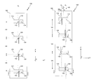
- FIG. 1 is front view of a vertically polarized antenna array in wide azimuth beamwidth setting.
- FIGS. 2A and 2B are cross sectional views along A-A datum detailing the motion of a vertically polarized antenna element in wide ( FIG. 2A ) and narrow ( FIG. 2B ) azimuth beamwidth setting.
- FIG. 2C is a back side view of the area immediate about the fourth radiating element with movable plate positioned as depicted in FIG. 2B .
- FIG. 3 is a front view of a vertically polarized antenna array in narrow azimuth beamwidth setting.
- FIG. 4 is an RF circuit diagram of an antenna array equipped with a Phase Shifter and Power Divider.
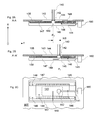
- FIGS. 5A and 5B together present a front view of a dual polarized antenna array configured for wide ( FIG. 5 a ) azimuth beamwidth setting and narrow ( FIG. 5B ) azimuth beamwidth setting.
- FIGS. 6A and 6B together present a front view of a dual polarized antenna array employing crossover dipole elements configured for wide ( FIG. 6A ) azimuth beamwidth setting and narrow ( FIG. 6B ) azimuth beamwidth setting.
- FIG. 7 depicts a wide azimuth radiation pattern corresponding to the FIG. 1 configuration (the radiation pattern for the embodiment of FIGS. 5A , 6 A is similar).
- FIG. 8 depicts narrow azimuth radiation pattern corresponding to the FIG. 3 configuration (the radiation pattern for the embodiment of FIGS. 5B , 6 B is similar).
- FIG. 1 shows a front view of a vertically polarized antenna array, 100 , according to an exemplary implementation, which utilizes a conventionally disposed reflector 105 .
- Reflector, 105 is oriented in a vertical orientation (Z-dimension) of the antenna array.
- the reflector, 105 may, for example, consist of an electrically conductive plate suitable for use with Radio Frequency (RF) signals.
- RF Radio Frequency
- reflector 105 plane is shown as a featureless rectangle, but in actual practice additional features (not shown) may be added to aid reflector performance.
- an antenna array, 100 contains a plurality of RF radiators ( 110 , 120 , 130 , 140 ) preferably arranged both vertically and horizontally in a single column arrangement along primary vertical axis disposed on shift-able 114 , 124 , 134 , 144 plates below the forward facing surface of the reflector 105 in the corresponding reflector orifices ( 113 , 123 , 133 , 143 ).
- each RF radiator ( 110 , 120 , 130 , and 140 ) is mounted on a feed-through ( 112 , 122 , 132 , 142 ) mount centrally disposed on a top surface of a shiftable foundation mount plate ( 114 , 124 , 134 , 144 ) capable of controllable orthogonal movement relative to the main vertical axis limited by the peripheral dimensions of the corresponding reflector orifices ( 113 , 123 , 133 , 143 ). Details pertaining to movable foundation mount plates ( 114 , 124 , 134 , 144 ) and relating structures will become apparent upon examination of FIG. 2A and FIG. 2B .
- RF radiators are preferably aligned along the common vertical axis labeled P 0 and are separated vertically by a distance VS.
- the plurality of RF radiators are separated by a distance VS in the range of 1 ⁇ 2 ⁇ - ⁇ from one another where ⁇ is the wavelength of the RF operating frequency.
- ⁇ is the wavelength of the RF operating frequency.
- frequencies of operation in a cellular network system are well known in the art.
- one range of RF frequencies may be between 806 MHz and 960 MHz.
- Alternative frequency ranges are possible with appropriate selection of frequency sensitive components.
- the common axis P 0 is the same as center vertical axis of the reflector 105 , plane.
- common axis P 0 is equidistant from the vertical edges of the of the reflector 105 , plane.
- RF radiator 110 , 120 , 130 , and 140
- SD should preferably be less than 1 ⁇ .
- a cross section datum A-A will be used to detail constructional and operational aspects relating to radiating elements relative movement. Drawing details of A-A datum can be found in FIG. 2A and FIG. 2B
- FIGS. 2A and 2B provide a cross sectional view along A-A datum.
- A-A datum bisects fourth 140 radiating element and associated mechanical structures.
- FIG. 2C provides a back side view of the area immediate of the fourth radiating 140 element. It shall be understood that all radiating elements share similar construction features, details being omitted for clarity.
- a vertically polarized radiating element 140 is mounted with a feed-through 142 mount.
- a feed through 142 mount is preferably constructed out of a dielectric material and provides isolation means between radiating element 140 and movable 144 plate.
- Movable 144 plate is preferably constructed utilizing a rigid material as long as plate's top surface is comprised of highly conductive material, but alternatively can be constructed from aluminum plate and the like.
- the RF signal for each radiating 110 , 120 , 130 , 140 element is individually supplied from a power dividing-combining 190 network with a suitable flexible radio wave 149 guide, such as flexible coaxial cable, and coupled to conventionally constructed feed through 142 mount terminals (details are not shown).
- Movable foundation mount plate 144 is recessed and mounted immediately below the bottom surface of reflector 105 plane and supported with a pair of sliding 147 guide frames, on each side reflector orifice 143 , having U-shaped slots 148 which provide X dimensional stability while providing Y dimensional movement to the movable foundation mount plate 144 .
- the back side of the movable foundation mount plate 144 and associated sliding 147 guide frames which are used for support are enclosed with a suitably constructed cover 145 to prevent undesirable back side radiation and to improve the front to back signal ratio.
- Actuator 180 provides mechanical motion means to the jack screw 141 .
- Jack screw rotation is coupled to a mechanical coupler 146 attached to the back side movable foundation mount plate 144 .
- By controlling direction and duration of rotation of the jack screw 141 subsequently provides Y dimensional movement to the movable foundation mount plate 144 .
- jack screw 141 is one of many possible means to achieve Y dimensional movement to the movable foundation mount plate 144 .
- the mechanical actuator 180 may be extended to provide mechanical motion means to other or preferably all other jack screws 111 , 121 , 131 used to control motion of respective radiating 110 , 120 , 130 , 140 elements.
- RF radiator ( 110 , 120 , 130 , 140 ) elements may be fed from a master RF input port, 210 , with the same relative phase angle RF signal through a conventionally designed RF power signal dividing-combining 190 network.
- RF power signal dividing-combining 190 network output-input 190 ( a - d ) ports are coupled with a suitable radio wave 119 , 129 , 139 , 149 guides, such as coaxial cable to corresponding radiating elements 110 , 120 , 130 , 140 .
- RF power signal 190 dividing-combining network may include remotely controllable phase shifting network so as to provide beam tilting capability as described in U.S. Pat. No.
- FIG. 4 An example of such implementation is shown in FIG. 4 wherein RF signal dividing-combining 190 network provides electrically controlled beam down-tilt capability. Phase shifting function of the power dividing network 190 may be remotely controlled via multipurpose control port 200 . Similarly, azimuth beamwidth control signals are coupled via multipurpose control port 200 to a mechanical actuator(s) 180 .
- a plurality of vertically polarized dipole 110 , 120 , 130 , 140 elements together form an antenna array useful for RF signal transmission and reception.
- vertically polarized dipole 110 , 120 , 130 , 140 elements can be replaced with a dual polarization radiating elements groups 310 , 320 , 330 , 340 which may utilize discrete radiating elements such as patches, taper slot, horn, folded dipole, and etc.
- FIG. 5A and FIG. 5B wherein radiating elements groups 310 , 320 , 330 , 340 are respectively mounted on movable foundation mount plates 314 , 324 , 334 , 344 .
- Conventional dipole radiating elements 310 ( a - d ) as shown in FIG. 5A and FIG. 5B can be replaced with cross over dipole pairs wherein radiating elements groups 310 , 320 , 330 , 340 are equivalently replaced with crossover dipole radiating elements groups 410 , 420 , 430 , 440 respectively mounted on movable foundation mount plates 314 , 324 , 334 , 344 .
- the resulting configuration, as depicted in FIG. 6 a and FIG. 6B generally operates in nearly identical manner as described hereinabove.
- the first group of RF radiators 120 , 140 is positioned along P 1 axis and the second group of RF radiators 110 , 130 is positioned along P 2 axis. Once all RF radiators ( 110 , 120 , 130 , 140 ) are positioned the resultant azimuth radiation beamwidth will be narrower. Such alignment setting will result in a relatively narrow azimuth beamwidth as shown in the simulation of FIG. 8 .
- HS can be varied continuously from minimum (0) to a maximum value to provide continuously variable azimuth variable beamwidth between two extreme settings described hereinabove.
- one embodiment of the invention includes a method for providing variable signal beamwidth by controlling positioning of the slidably mounted radiators relative to the reflector and each other.
- the method may control beamwidth by setting the radiator positioning to a first position corresponding to operating condition (a) above wherein all RF radiators ( 110 , 120 , 130 , 140 ), as depicted in FIG. 1 , are aligned to obtain a relatively wide beamwidth setting.
- the method may further control beamwidth by setting the radiator positioning to a second position where the radiators are staggered, for example corresponding to operating condition (b) above to obtain a relatively narrow beamwidth.
- first and second settings may of course be varied in between the example settings (a) and (b) in accordance with the beamwidth control signals to provide the desired beamwidth.
- the method of the invention may also provide variable beam tilt.
- variable beam tilt is provided by controlling the phase of the RF signals applied to the radiators through a remotely controllable phase shifting network such as described above in relation to FIG. 4 .
Abstract
Description
SD=√{square root over (4HS 2 +VS 2)}
SD=VS
SD=√{square root over (4HS 2 +VS 2)}
SD=√{square root over (4HS 2 +VS 2)}
- 100 Vertical polarization movable stagger antenna array
- 101 Dual polarization movable stagger antenna array
- 102 Dual polarization movable stagger antenna array equipped with crossover dipole radiating elements
- 105 Antenna Reflector
- 110 First Radiating Element (in this case a dipole)
- 111 First jack screw
- 112 Feed-through mount
- 113 First Radiating Element Reflector orifice
- 114 First movable plate
- 115 First back cover
- 116 First mechanical coupler cover
- 117 Sliding guide frames
- 118 Sliding guide slot in a sliding guide frames
- 119 First Radiating Element feed line (coax) to RF power dividing and combining network
- 120 Second Radiating Element (in this case a dipole)
- 129 Second Radiating Element feed line (coax) to RF power dividing and combining network
- 130 Third Radiating Element (in this case a dipole)
- 139 Third Radiating Element feed line (coax) to RF power dividing and combining network
- 140 Fourth Radiating Element (in this case a dipole)
- 141 Fourth mechanical actuator coupling
- 142 Fourth pivoting joint
- 143 Fourth Radiating Element feed line to RF power dividing and combining network
- 140 Fourth Radiating Element (in this case a dipole)
- 141 Fourth jack screw
- 142 Fourth Feed-through mount
- 143 Fourth Radiating Element Reflector orifice
- 144 Fourth movable plate
- 145 Fourth back cover
- 146 Fourth mechanical coupler cover
- 147 Sliding guide frames
- 148 Sliding guide slot in a sliding guide frames
- 149 Fourth Radiating Element feed line (coax) to RF power dividing and combining network
- 180 Mechanical Azimuth Actuator
- 190 RF power dividing and combining network with integrated remote electrical tilt capability
- 190(a-d) RF power dividing and combining network to antenna coupling ports.
- 200 Multipurpose communication port
- 210 Common RF port
- 310 First dual polarization radiating element grouping.
- 310(a-b) Radiation elements used in first dual polarization radiating element group
- 313 First Radiating Element Reflector orifice for dual polarization group
- 314 First movable plate for dual polarization group
- 320 Second dual polarization radiating element grouping.
- 320(a-b) Radiation elements used in second dual polarization radiating element group
- 323 Second Radiating Element Reflector orifice for dual polarization group
- 324 Second movable plate for dual polarization group
- 330 Third dual polarization radiating element grouping.
- 330(a-b) Radiation elements used in third dual polarization radiating element group
- 333 Third Radiating Element Reflector orifice for dual polarization group
- 334 Third movable plate for dual polarization group
- 340 Fourth dual polarization radiating element grouping.
- 340(a-b) Radiation elements used in fourth dual polarization radiating element group
- 343 Fourth Radiating Element Reflector orifice for dual polarization group
- 344 Fourth movable plate for dual polarization group
- 410 First dual polarization radiating element grouping utilizing crossover dipoles.
- 420 Second dual polarization radiating element grouping utilizing crossover dipoles.
- 430 Third dual polarization radiating element grouping utilizing crossover dipoles.
- 440 Fourth dual polarization radiating element grouping utilizing crossover dipoles.
Claims (14)
SD=√{square root over (4HS 2 +VS 2)}
Priority Applications (1)
| Application Number | Priority Date | Filing Date | Title |
|---|---|---|---|
| US12/080,483 US8330668B2 (en) | 2007-04-06 | 2008-04-03 | Dual stagger off settable azimuth beam width controlled antenna for wireless network |
Applications Claiming Priority (2)
| Application Number | Priority Date | Filing Date | Title |
|---|---|---|---|
| US92213007P | 2007-04-06 | 2007-04-06 | |
| US12/080,483 US8330668B2 (en) | 2007-04-06 | 2008-04-03 | Dual stagger off settable azimuth beam width controlled antenna for wireless network |
Publications (2)
| Publication Number | Publication Date |
|---|---|
| US20080246681A1 US20080246681A1 (en) | 2008-10-09 |
| US8330668B2 true US8330668B2 (en) | 2012-12-11 |
Family
ID=39826474
Family Applications (1)
| Application Number | Title | Priority Date | Filing Date |
|---|---|---|---|
| US12/080,483 Active 2029-02-20 US8330668B2 (en) | 2007-04-06 | 2008-04-03 | Dual stagger off settable azimuth beam width controlled antenna for wireless network |
Country Status (2)
| Country | Link |
|---|---|
| US (1) | US8330668B2 (en) |
| WO (1) | WO2008124027A1 (en) |
Cited By (2)
| Publication number | Priority date | Publication date | Assignee | Title |
|---|---|---|---|---|
| US20130169495A1 (en) * | 2011-12-30 | 2013-07-04 | Gemintek Corporation | Multi-point driving device for general purpose base station antenna |
| US10205229B2 (en) * | 2015-12-04 | 2019-02-12 | Mitsubishi Electric Corporation | Wave energy radiating apparatus |
Families Citing this family (7)
| Publication number | Priority date | Publication date | Assignee | Title |
|---|---|---|---|---|
| US7920100B2 (en) * | 2005-08-18 | 2011-04-05 | Raytheon Company | Foldable reflect array |
| KR100834724B1 (en) * | 2006-06-07 | 2008-06-05 | 주식회사 이엠따블유안테나 | Array antenna system automatically adjusting space between arranged antennas |
| EP2165388B1 (en) | 2007-06-13 | 2018-01-17 | Intel Corporation | Triple stagger offsetable azimuth beam width controlled antenna for wireless network |
| WO2009061966A1 (en) | 2007-11-09 | 2009-05-14 | Powerwave Technologies, Inc. | Variable stagger reflector for azimuth beam width controlled antenna |
| US8508427B2 (en) * | 2008-01-28 | 2013-08-13 | P-Wave Holdings, Llc | Tri-column adjustable azimuth beam width antenna for wireless network |
| KR20140109708A (en) * | 2013-03-06 | 2014-09-16 | 주식회사 케이엠더블유 | Vertical array with the antenna radiating elements |
| CN112640215B (en) * | 2018-08-24 | 2022-09-23 | 康普技术有限责任公司 | Lensed base station antenna with staggered vertical array for azimuth beamwidth stabilization |
Citations (46)
| Publication number | Priority date | Publication date | Assignee | Title |
|---|---|---|---|---|
| US1795397A (en) | 1927-12-29 | 1931-03-10 | American Telephone & Telegraph | Directionally-selective radio receiving system |
| US2473421A (en) | 1945-05-30 | 1949-06-14 | Fubini Eugene | Search antenna array |
| US2535049A (en) | 1945-11-14 | 1950-12-26 | Standard Telephones Cables Ltd | Antenna structure |
| EP0566522A1 (en) | 1992-04-15 | 1993-10-20 | Celwave R.F. A/S | Antenna system and method of manufacturing said system |
| US5274391A (en) | 1990-10-25 | 1993-12-28 | Radio Frequency Systems, Inc. | Broadband directional antenna having binary feed network with microstrip transmission line |
| US5572222A (en) | 1993-06-25 | 1996-11-05 | Allen Telecom Group | Microstrip patch antenna array |
| US5949303A (en) | 1995-05-24 | 1999-09-07 | Allgon Ab | Movable dielectric body for controlling propagation velocity in a feed line |
| US5966102A (en) * | 1995-12-14 | 1999-10-12 | Ems Technologies, Inc. | Dual polarized array antenna with central polarization control |
| US5969689A (en) | 1997-01-13 | 1999-10-19 | Metawave Communications Corporation | Multi-sector pivotal antenna system and method |
| US6034649A (en) | 1998-10-14 | 2000-03-07 | Andrew Corporation | Dual polarized based station antenna |
| EP1098391A2 (en) | 1999-11-03 | 2001-05-09 | Andrew A.G. | Folded dipole antenna |
| US6285336B1 (en) | 1999-11-03 | 2001-09-04 | Andrew Corporation | Folded dipole antenna |
| US20020008672A1 (en) * | 1998-09-21 | 2002-01-24 | Tantivy Communications, Inc. | Adaptive antenna for use in wireless communication systems |
| US20020135528A1 (en) * | 2001-03-20 | 2002-09-26 | Anthony Teillet | Antenna array having air dielectric stripline feed system |
| US20020149529A1 (en) | 2001-04-17 | 2002-10-17 | Fleming Debra A. | Broadband antenna structure |
| US6515633B2 (en) | 2000-11-17 | 2003-02-04 | Ems Technologies, Inc. | Radio frequency isolation card |
| US6529172B2 (en) | 2000-08-11 | 2003-03-04 | Andrew Corporation | Dual-polarized radiating element with high isolation between polarization channels |
| US6567055B1 (en) | 2001-05-01 | 2003-05-20 | Rockwell Collins, Inc. | Method and system for generating a balanced feed for RF circuit |
| US20040051677A1 (en) * | 2001-10-11 | 2004-03-18 | Goettl Maximilian | Dual-polarization antenna array |
| US6717555B2 (en) | 2001-03-20 | 2004-04-06 | Andrew Corporation | Antenna array |
| US6747606B2 (en) | 2002-05-31 | 2004-06-08 | Radio Frequency Systems Inc. | Single or dual polarized molded dipole antenna having integrated feed structure |
| US6756939B2 (en) | 2000-07-21 | 2004-06-29 | Paratek Microwave, Inc. | Phased array antennas incorporating voltage-tunable phase shifters |
| US6809694B2 (en) | 2002-09-26 | 2004-10-26 | Andrew Corporation | Adjustable beamwidth and azimuth scanning antenna with dipole elements |
| US6822618B2 (en) | 2003-03-17 | 2004-11-23 | Andrew Corporation | Folded dipole antenna, coaxial to microstrip transition, and retaining element |
| US6864837B2 (en) | 2003-07-18 | 2005-03-08 | Ems Technologies, Inc. | Vertical electrical downtilt antenna |
| WO2005060045A1 (en) | 2003-12-18 | 2005-06-30 | Kathrein-Werke Kg | Mobile radio antenna array for a base station |
| US6922169B2 (en) | 2003-02-14 | 2005-07-26 | Andrew Corporation | Antenna, base station and power coupler |
| US6924776B2 (en) | 2003-07-03 | 2005-08-02 | Andrew Corporation | Wideband dual polarized base station antenna offering optimized horizontal beam radiation patterns and variable vertical beam tilt |
| US6950061B2 (en) | 2001-11-09 | 2005-09-27 | Ems Technologies, Inc. | Antenna array for moving vehicles |
| US20050219140A1 (en) | 2004-04-01 | 2005-10-06 | Stella Doradus Waterford Limited | Antenna construction |
| US20050231437A1 (en) | 2004-04-16 | 2005-10-20 | Hon Hai Precision Ind. Co., Ltd. | Dipole antenna |
| US7006053B2 (en) | 2003-05-01 | 2006-02-28 | Intermec Ip Corp. | Adjustable reflector system for fixed dipole antenna |
| US7151498B2 (en) | 2004-03-09 | 2006-12-19 | The Boeing Company | System and method for preferentially controlling grating lobes of direct radiating arrays |
| US20070008236A1 (en) * | 2005-07-06 | 2007-01-11 | Ems Technologies, Inc. | Compact dual-band antenna system |
| US7173572B2 (en) * | 2002-02-28 | 2007-02-06 | Andrew Corporation | Dual band, dual pole, 90 degree azimuth BW, variable downtilt antenna |
| US20070030208A1 (en) * | 2003-06-16 | 2007-02-08 | Linehan Kevin E | Cellular antenna and systems and methods therefor |
| US20070146222A1 (en) | 2005-10-16 | 2007-06-28 | Starling Advanced Communications Ltd. | Low profile antenna |
| US20070205952A1 (en) | 2006-03-03 | 2007-09-06 | Gang Yi Deng | Broadband single vertical polarized base station antenna |
| US20070241979A1 (en) | 2003-06-16 | 2007-10-18 | Ching-Shun Yang | Base station antenna rotation mechanism |
| US7358922B2 (en) | 2002-12-13 | 2008-04-15 | Commscope, Inc. Of North Carolina | Directed dipole antenna |
| US7405710B2 (en) | 2002-03-26 | 2008-07-29 | Andrew Corporation | Multiband dual polarized adjustable beamtilt base station antenna |
| EP1950832A1 (en) | 2005-11-14 | 2008-07-30 | Anritsu Corporation | Rectilinear polarization antenna and radar device using the same |
| US20080309568A1 (en) * | 2007-06-13 | 2008-12-18 | Gang Yi Deng | Triple stagger offsetable azimuth beam width controlled antenna for wireless network |
| US20090015498A1 (en) | 2007-03-08 | 2009-01-15 | Gang Yi Deng | Dual staggered vertically polarized variable azimuth beamwidth antenna for wireless network |
| US20090262039A1 (en) * | 2008-04-21 | 2009-10-22 | Spx Corporation | Phased-Array Antenna Radiator for a Super Economical Broadcast System |
| US7710344B2 (en) | 2007-03-05 | 2010-05-04 | Powerwave Technologies, Inc. | Single pole vertically polarized variable azimuth beamwidth antenna for wireless network |
-
2008
- 2008-04-03 US US12/080,483 patent/US8330668B2/en active Active
- 2008-04-03 WO PCT/US2008/004332 patent/WO2008124027A1/en active Application Filing
Patent Citations (51)
| Publication number | Priority date | Publication date | Assignee | Title |
|---|---|---|---|---|
| US1795397A (en) | 1927-12-29 | 1931-03-10 | American Telephone & Telegraph | Directionally-selective radio receiving system |
| US2473421A (en) | 1945-05-30 | 1949-06-14 | Fubini Eugene | Search antenna array |
| US2535049A (en) | 1945-11-14 | 1950-12-26 | Standard Telephones Cables Ltd | Antenna structure |
| US5274391A (en) | 1990-10-25 | 1993-12-28 | Radio Frequency Systems, Inc. | Broadband directional antenna having binary feed network with microstrip transmission line |
| EP0566522A1 (en) | 1992-04-15 | 1993-10-20 | Celwave R.F. A/S | Antenna system and method of manufacturing said system |
| US5572222A (en) | 1993-06-25 | 1996-11-05 | Allen Telecom Group | Microstrip patch antenna array |
| US5949303A (en) | 1995-05-24 | 1999-09-07 | Allgon Ab | Movable dielectric body for controlling propagation velocity in a feed line |
| US6067053A (en) | 1995-12-14 | 2000-05-23 | Ems Technologies, Inc. | Dual polarized array antenna |
| US5966102A (en) * | 1995-12-14 | 1999-10-12 | Ems Technologies, Inc. | Dual polarized array antenna with central polarization control |
| US5969689A (en) | 1997-01-13 | 1999-10-19 | Metawave Communications Corporation | Multi-sector pivotal antenna system and method |
| US20020008672A1 (en) * | 1998-09-21 | 2002-01-24 | Tantivy Communications, Inc. | Adaptive antenna for use in wireless communication systems |
| US6034649A (en) | 1998-10-14 | 2000-03-07 | Andrew Corporation | Dual polarized based station antenna |
| EP1098391A2 (en) | 1999-11-03 | 2001-05-09 | Andrew A.G. | Folded dipole antenna |
| US6285336B1 (en) | 1999-11-03 | 2001-09-04 | Andrew Corporation | Folded dipole antenna |
| US6756939B2 (en) | 2000-07-21 | 2004-06-29 | Paratek Microwave, Inc. | Phased array antennas incorporating voltage-tunable phase shifters |
| US6529172B2 (en) | 2000-08-11 | 2003-03-04 | Andrew Corporation | Dual-polarized radiating element with high isolation between polarization channels |
| US6933905B2 (en) | 2000-11-17 | 2005-08-23 | Ems Technologies, Inc. | RF card with conductive strip |
| US6515633B2 (en) | 2000-11-17 | 2003-02-04 | Ems Technologies, Inc. | Radio frequency isolation card |
| US20020135528A1 (en) * | 2001-03-20 | 2002-09-26 | Anthony Teillet | Antenna array having air dielectric stripline feed system |
| US6697029B2 (en) | 2001-03-20 | 2004-02-24 | Andrew Corporation | Antenna array having air dielectric stripline feed system |
| US6717555B2 (en) | 2001-03-20 | 2004-04-06 | Andrew Corporation | Antenna array |
| US7075497B2 (en) | 2001-03-20 | 2006-07-11 | Andrew Corporation | Antenna array |
| US20020149529A1 (en) | 2001-04-17 | 2002-10-17 | Fleming Debra A. | Broadband antenna structure |
| US6567055B1 (en) | 2001-05-01 | 2003-05-20 | Rockwell Collins, Inc. | Method and system for generating a balanced feed for RF circuit |
| US20040051677A1 (en) * | 2001-10-11 | 2004-03-18 | Goettl Maximilian | Dual-polarization antenna array |
| US6985123B2 (en) * | 2001-10-11 | 2006-01-10 | Kathrein-Werke Kg | Dual-polarization antenna array |
| US6950061B2 (en) | 2001-11-09 | 2005-09-27 | Ems Technologies, Inc. | Antenna array for moving vehicles |
| US7173572B2 (en) * | 2002-02-28 | 2007-02-06 | Andrew Corporation | Dual band, dual pole, 90 degree azimuth BW, variable downtilt antenna |
| US7405710B2 (en) | 2002-03-26 | 2008-07-29 | Andrew Corporation | Multiband dual polarized adjustable beamtilt base station antenna |
| US6747606B2 (en) | 2002-05-31 | 2004-06-08 | Radio Frequency Systems Inc. | Single or dual polarized molded dipole antenna having integrated feed structure |
| US6809694B2 (en) | 2002-09-26 | 2004-10-26 | Andrew Corporation | Adjustable beamwidth and azimuth scanning antenna with dipole elements |
| US7358922B2 (en) | 2002-12-13 | 2008-04-15 | Commscope, Inc. Of North Carolina | Directed dipole antenna |
| US6922169B2 (en) | 2003-02-14 | 2005-07-26 | Andrew Corporation | Antenna, base station and power coupler |
| US6822618B2 (en) | 2003-03-17 | 2004-11-23 | Andrew Corporation | Folded dipole antenna, coaxial to microstrip transition, and retaining element |
| US7006053B2 (en) | 2003-05-01 | 2006-02-28 | Intermec Ip Corp. | Adjustable reflector system for fixed dipole antenna |
| US20070030208A1 (en) * | 2003-06-16 | 2007-02-08 | Linehan Kevin E | Cellular antenna and systems and methods therefor |
| US20070241979A1 (en) | 2003-06-16 | 2007-10-18 | Ching-Shun Yang | Base station antenna rotation mechanism |
| US6924776B2 (en) | 2003-07-03 | 2005-08-02 | Andrew Corporation | Wideband dual polarized base station antenna offering optimized horizontal beam radiation patterns and variable vertical beam tilt |
| US6864837B2 (en) | 2003-07-18 | 2005-03-08 | Ems Technologies, Inc. | Vertical electrical downtilt antenna |
| WO2005060045A1 (en) | 2003-12-18 | 2005-06-30 | Kathrein-Werke Kg | Mobile radio antenna array for a base station |
| US7151498B2 (en) | 2004-03-09 | 2006-12-19 | The Boeing Company | System and method for preferentially controlling grating lobes of direct radiating arrays |
| US20050219140A1 (en) | 2004-04-01 | 2005-10-06 | Stella Doradus Waterford Limited | Antenna construction |
| US20050231437A1 (en) | 2004-04-16 | 2005-10-20 | Hon Hai Precision Ind. Co., Ltd. | Dipole antenna |
| US20070008236A1 (en) * | 2005-07-06 | 2007-01-11 | Ems Technologies, Inc. | Compact dual-band antenna system |
| US20070146222A1 (en) | 2005-10-16 | 2007-06-28 | Starling Advanced Communications Ltd. | Low profile antenna |
| EP1950832A1 (en) | 2005-11-14 | 2008-07-30 | Anritsu Corporation | Rectilinear polarization antenna and radar device using the same |
| US20070205952A1 (en) | 2006-03-03 | 2007-09-06 | Gang Yi Deng | Broadband single vertical polarized base station antenna |
| US7710344B2 (en) | 2007-03-05 | 2010-05-04 | Powerwave Technologies, Inc. | Single pole vertically polarized variable azimuth beamwidth antenna for wireless network |
| US20090015498A1 (en) | 2007-03-08 | 2009-01-15 | Gang Yi Deng | Dual staggered vertically polarized variable azimuth beamwidth antenna for wireless network |
| US20080309568A1 (en) * | 2007-06-13 | 2008-12-18 | Gang Yi Deng | Triple stagger offsetable azimuth beam width controlled antenna for wireless network |
| US20090262039A1 (en) * | 2008-04-21 | 2009-10-22 | Spx Corporation | Phased-Array Antenna Radiator for a Super Economical Broadcast System |
Non-Patent Citations (6)
| Title |
|---|
| International Search Authority, Written Opinion for International Application No. PCT/US08/02845 dated Jun. 2, 2008, 7 pages. |
| International Search Authority, Written Opinion for International Application No. PCT/US08/03176 dated Jun. 11, 2008, 8 pages. |
| International Search Authority, Written Opinion pertaining to Application No. PCT/US08/04332 mailed Jun. 20, 2008. |
| Office Action dated Dec. 22, 2010 from U.S. Appl. No. 12/157,646. |
| Office Action dated Jul. 21, 2011 from U.S. Appl. No. 12/157,646. |
| Supplemental European Search Report pertaining to European Patent Application No. 07751869.4/PCT/2007005137 mailed Feb. 4, 2010. |
Cited By (3)
| Publication number | Priority date | Publication date | Assignee | Title |
|---|---|---|---|---|
| US20130169495A1 (en) * | 2011-12-30 | 2013-07-04 | Gemintek Corporation | Multi-point driving device for general purpose base station antenna |
| US8890756B2 (en) * | 2011-12-30 | 2014-11-18 | Gemintek Corporation | Multi-point driving device for general purpose base station antenna |
| US10205229B2 (en) * | 2015-12-04 | 2019-02-12 | Mitsubishi Electric Corporation | Wave energy radiating apparatus |
Also Published As
| Publication number | Publication date |
|---|---|
| WO2008124027A1 (en) | 2008-10-16 |
| US20080246681A1 (en) | 2008-10-09 |
Similar Documents
| Publication | Publication Date | Title |
|---|---|---|
| US9806412B2 (en) | Triple stagger offsetable azimuth beam width controlled antenna for wireless network | |
| US7990329B2 (en) | Dual staggered vertically polarized variable azimuth beamwidth antenna for wireless network | |
| US8330668B2 (en) | Dual stagger off settable azimuth beam width controlled antenna for wireless network | |
| US20090021437A1 (en) | Center panel movable three-column array antenna for wireless network | |
| US10079431B2 (en) | Antenna array having mechanically-adjustable radiator elements | |
| US20170062952A1 (en) | Dual band, multi column antenna array for wireless network | |
| US8237619B2 (en) | Dual beam sector antenna array with low loss beam forming network | |
| CA2416957C (en) | Antenna apparatus | |
| EP1221182B1 (en) | Mechanically adjustable phase-shifting parasitic antenna element | |
| US7710344B2 (en) | Single pole vertically polarized variable azimuth beamwidth antenna for wireless network | |
| US6067054A (en) | Method and arrangement relating to antennas | |
| US20210320399A1 (en) | Base station antennas having arrays of radiating elements with 4 ports without usage of diplexers | |
| KR20070088696A (en) | An antenna arrangement and a method relating thereto | |
| US20220173504A1 (en) | Base station antennas having arrays with both mechanical uptilt and electronic downtilt | |
| CA2506198C (en) | Two-dimensional antenna array | |
| EP2218119B1 (en) | Variable stagger reflector for azimuth beam width controlled antenna | |
| CN112366454A (en) | Active array antenna and mobile communication base station | |
| GB2426635A (en) | Phase shifting arrangement | |
| WO2019082447A1 (en) | Antenna | |
| KR102590419B1 (en) | Liquid crystal-based phased array antenna | |
| CN212783781U (en) | Dual beam base station antenna with integrated beam forming network | |
| US20240128638A1 (en) | Twin-beam antennas having hybrid couplers |
Legal Events
| Date | Code | Title | Description |
|---|---|---|---|
| AS | Assignment |
Owner name: POWERWAVE TECHNOLOGIES, INC., CALIFORNIA Free format text: ASSIGNMENT OF ASSIGNORS INTEREST;ASSIGNORS:DENG, GANG YI;VASSILAKIS, BILL;HUNTON, MATTHEW J.;AND OTHERS;REEL/FRAME:021840/0553;SIGNING DATES FROM 20080325 TO 20080331 Owner name: POWERWAVE TECHNOLOGIES, INC., CALIFORNIA Free format text: ASSIGNMENT OF ASSIGNORS INTEREST;ASSIGNORS:DENG, GANG YI;VASSILAKIS, BILL;HUNTON, MATTHEW J.;AND OTHERS;SIGNING DATES FROM 20080325 TO 20080331;REEL/FRAME:021840/0553 |
|
| AS | Assignment |
Owner name: WELLS FARGO FOOTHILL, LLC, AS AGENT, CALIFORNIA Free format text: PATENT SECURITY AGREEMENT;ASSIGNOR:POWERWAVE TECHNOLOGIES, INC.;REEL/FRAME:022507/0027 Effective date: 20090403 Owner name: WELLS FARGO FOOTHILL, LLC, AS AGENT,CALIFORNIA Free format text: PATENT SECURITY AGREEMENT;ASSIGNOR:POWERWAVE TECHNOLOGIES, INC.;REEL/FRAME:022507/0027 Effective date: 20090403 |
|
| AS | Assignment |
Owner name: POWERWAVE TECHNOLOGIES, INC., CALIFORNIA Free format text: RELEASE BY SECURED PARTY;ASSIGNOR:WELLS FARGO CAPITAL FINANCE, LLC, FKA WELLS FARGO FOOTHILL, LLC;REEL/FRAME:028819/0014 Effective date: 20120820 |
|
| STCF | Information on status: patent grant |
Free format text: PATENTED CASE |
|
| FEPP | Fee payment procedure |
Free format text: PAYOR NUMBER ASSIGNED (ORIGINAL EVENT CODE: ASPN); ENTITY STATUS OF PATENT OWNER: LARGE ENTITY |
|
| AS | Assignment |
Owner name: P-WAVE HOLDINGS, LLC, CALIFORNIA Free format text: SECURITY AGREEMENT;ASSIGNOR:POWERWAVE TECHNOLOGIES, INC.;REEL/FRAME:029469/0556 Effective date: 20121212 |
|
| AS | Assignment |
Owner name: P-WAVE HOLDINGS, LLC, CALIFORNIA Free format text: ASSIGNMENT OF ASSIGNORS INTEREST;ASSIGNOR:POWERWAVE TECHNOLOGIES, INC.;REEL/FRAME:031718/0801 Effective date: 20130522 |
|
| AS | Assignment |
Owner name: POWERWAVE TECHNOLOGIES S.A.R.L., LUXEMBOURG Free format text: ASSIGNMENT OF ASSIGNORS INTEREST;ASSIGNOR:P-WAVE HOLDINGS, LLC;REEL/FRAME:032364/0916 Effective date: 20140220 |
|
| AS | Assignment |
Owner name: INTEL CORPORATION, CALIFORNIA Free format text: ASSIGNMENT OF ASSIGNORS INTEREST;ASSIGNOR:POWERWAVE TECHNOLOGIES S.A.R.L.;REEL/FRAME:034216/0001 Effective date: 20140827 |
|
| FEPP | Fee payment procedure |
Free format text: PAYOR NUMBER ASSIGNED (ORIGINAL EVENT CODE: ASPN); ENTITY STATUS OF PATENT OWNER: LARGE ENTITY Free format text: PAYER NUMBER DE-ASSIGNED (ORIGINAL EVENT CODE: RMPN); ENTITY STATUS OF PATENT OWNER: LARGE ENTITY |
|
| FPAY | Fee payment |
Year of fee payment: 4 |
|
| MAFP | Maintenance fee payment |
Free format text: PAYMENT OF MAINTENANCE FEE, 8TH YEAR, LARGE ENTITY (ORIGINAL EVENT CODE: M1552); ENTITY STATUS OF PATENT OWNER: LARGE ENTITY Year of fee payment: 8 |
|
| MAFP | Maintenance fee payment |
Free format text: PAYMENT OF MAINTENANCE FEE, 12TH YEAR, LARGE ENTITY (ORIGINAL EVENT CODE: M1553); ENTITY STATUS OF PATENT OWNER: LARGE ENTITY Year of fee payment: 12 |