US8337593B2 - Process for purifying natural gas and regenerating one or more adsorbers - Google Patents
Process for purifying natural gas and regenerating one or more adsorbers Download PDFInfo
- Publication number
- US8337593B2 US8337593B2 US12/859,166 US85916610A US8337593B2 US 8337593 B2 US8337593 B2 US 8337593B2 US 85916610 A US85916610 A US 85916610A US 8337593 B2 US8337593 B2 US 8337593B2
- Authority
- US
- United States
- Prior art keywords
- adsorber
- gas
- natural gas
- process according
- regeneration
- Prior art date
- Legal status (The legal status is an assumption and is not a legal conclusion. Google has not performed a legal analysis and makes no representation as to the accuracy of the status listed.)
- Active, expires
Links
Images

Classifications
-
- B—PERFORMING OPERATIONS; TRANSPORTING
- B01—PHYSICAL OR CHEMICAL PROCESSES OR APPARATUS IN GENERAL
- B01D—SEPARATION
- B01D53/00—Separation of gases or vapours; Recovering vapours of volatile solvents from gases; Chemical or biological purification of waste gases, e.g. engine exhaust gases, smoke, fumes, flue gases, aerosols
- B01D53/26—Drying gases or vapours
- B01D53/261—Drying gases or vapours by adsorption
-
- B—PERFORMING OPERATIONS; TRANSPORTING
- B01—PHYSICAL OR CHEMICAL PROCESSES OR APPARATUS IN GENERAL
- B01D—SEPARATION
- B01D53/00—Separation of gases or vapours; Recovering vapours of volatile solvents from gases; Chemical or biological purification of waste gases, e.g. engine exhaust gases, smoke, fumes, flue gases, aerosols
- B01D53/02—Separation of gases or vapours; Recovering vapours of volatile solvents from gases; Chemical or biological purification of waste gases, e.g. engine exhaust gases, smoke, fumes, flue gases, aerosols by adsorption, e.g. preparative gas chromatography
- B01D53/04—Separation of gases or vapours; Recovering vapours of volatile solvents from gases; Chemical or biological purification of waste gases, e.g. engine exhaust gases, smoke, fumes, flue gases, aerosols by adsorption, e.g. preparative gas chromatography with stationary adsorbents
- B01D53/0407—Constructional details of adsorbing systems
- B01D53/0438—Cooling or heating systems
-
- B—PERFORMING OPERATIONS; TRANSPORTING
- B01—PHYSICAL OR CHEMICAL PROCESSES OR APPARATUS IN GENERAL
- B01D—SEPARATION
- B01D53/00—Separation of gases or vapours; Recovering vapours of volatile solvents from gases; Chemical or biological purification of waste gases, e.g. engine exhaust gases, smoke, fumes, flue gases, aerosols
- B01D53/34—Chemical or biological purification of waste gases
- B01D53/46—Removing components of defined structure
- B01D53/62—Carbon oxides
-
- C—CHEMISTRY; METALLURGY
- C10—PETROLEUM, GAS OR COKE INDUSTRIES; TECHNICAL GASES CONTAINING CARBON MONOXIDE; FUELS; LUBRICANTS; PEAT
- C10L—FUELS NOT OTHERWISE PROVIDED FOR; NATURAL GAS; SYNTHETIC NATURAL GAS OBTAINED BY PROCESSES NOT COVERED BY SUBCLASSES C10G, C10K; LIQUEFIED PETROLEUM GAS; ADDING MATERIALS TO FUELS OR FIRES TO REDUCE SMOKE OR UNDESIRABLE DEPOSITS OR TO FACILITATE SOOT REMOVAL; FIRELIGHTERS
- C10L3/00—Gaseous fuels; Natural gas; Synthetic natural gas obtained by processes not covered by subclass C10G, C10K; Liquefied petroleum gas
- C10L3/06—Natural gas; Synthetic natural gas obtained by processes not covered by C10G, C10K3/02 or C10K3/04
- C10L3/10—Working-up natural gas or synthetic natural gas
- C10L3/101—Removal of contaminants
- C10L3/102—Removal of contaminants of acid contaminants
- C10L3/104—Carbon dioxide
-
- C—CHEMISTRY; METALLURGY
- C10—PETROLEUM, GAS OR COKE INDUSTRIES; TECHNICAL GASES CONTAINING CARBON MONOXIDE; FUELS; LUBRICANTS; PEAT
- C10L—FUELS NOT OTHERWISE PROVIDED FOR; NATURAL GAS; SYNTHETIC NATURAL GAS OBTAINED BY PROCESSES NOT COVERED BY SUBCLASSES C10G, C10K; LIQUEFIED PETROLEUM GAS; ADDING MATERIALS TO FUELS OR FIRES TO REDUCE SMOKE OR UNDESIRABLE DEPOSITS OR TO FACILITATE SOOT REMOVAL; FIRELIGHTERS
- C10L3/00—Gaseous fuels; Natural gas; Synthetic natural gas obtained by processes not covered by subclass C10G, C10K; Liquefied petroleum gas
- C10L3/06—Natural gas; Synthetic natural gas obtained by processes not covered by C10G, C10K3/02 or C10K3/04
- C10L3/10—Working-up natural gas or synthetic natural gas
- C10L3/101—Removal of contaminants
- C10L3/106—Removal of contaminants of water
-
- B—PERFORMING OPERATIONS; TRANSPORTING
- B01—PHYSICAL OR CHEMICAL PROCESSES OR APPARATUS IN GENERAL
- B01D—SEPARATION
- B01D2253/00—Adsorbents used in seperation treatment of gases and vapours
- B01D2253/10—Inorganic adsorbents
- B01D2253/102—Carbon
-
- B—PERFORMING OPERATIONS; TRANSPORTING
- B01—PHYSICAL OR CHEMICAL PROCESSES OR APPARATUS IN GENERAL
- B01D—SEPARATION
- B01D2253/00—Adsorbents used in seperation treatment of gases and vapours
- B01D2253/10—Inorganic adsorbents
- B01D2253/104—Alumina
-
- B—PERFORMING OPERATIONS; TRANSPORTING
- B01—PHYSICAL OR CHEMICAL PROCESSES OR APPARATUS IN GENERAL
- B01D—SEPARATION
- B01D2253/00—Adsorbents used in seperation treatment of gases and vapours
- B01D2253/10—Inorganic adsorbents
- B01D2253/106—Silica or silicates
-
- B—PERFORMING OPERATIONS; TRANSPORTING
- B01—PHYSICAL OR CHEMICAL PROCESSES OR APPARATUS IN GENERAL
- B01D—SEPARATION
- B01D2253/00—Adsorbents used in seperation treatment of gases and vapours
- B01D2253/10—Inorganic adsorbents
- B01D2253/106—Silica or silicates
- B01D2253/108—Zeolites
-
- B—PERFORMING OPERATIONS; TRANSPORTING
- B01—PHYSICAL OR CHEMICAL PROCESSES OR APPARATUS IN GENERAL
- B01D—SEPARATION
- B01D2256/00—Main component in the product gas stream after treatment
- B01D2256/24—Hydrocarbons
- B01D2256/245—Methane
-
- B—PERFORMING OPERATIONS; TRANSPORTING
- B01—PHYSICAL OR CHEMICAL PROCESSES OR APPARATUS IN GENERAL
- B01D—SEPARATION
- B01D2257/00—Components to be removed
- B01D2257/30—Sulfur compounds
- B01D2257/304—Hydrogen sulfide
-
- B—PERFORMING OPERATIONS; TRANSPORTING
- B01—PHYSICAL OR CHEMICAL PROCESSES OR APPARATUS IN GENERAL
- B01D—SEPARATION
- B01D2257/00—Components to be removed
- B01D2257/50—Carbon oxides
- B01D2257/504—Carbon dioxide
-
- B—PERFORMING OPERATIONS; TRANSPORTING
- B01—PHYSICAL OR CHEMICAL PROCESSES OR APPARATUS IN GENERAL
- B01D—SEPARATION
- B01D2257/00—Components to be removed
- B01D2257/80—Water
-
- B—PERFORMING OPERATIONS; TRANSPORTING
- B01—PHYSICAL OR CHEMICAL PROCESSES OR APPARATUS IN GENERAL
- B01D—SEPARATION
- B01D2259/00—Type of treatment
- B01D2259/40—Further details for adsorption processes and devices
- B01D2259/40083—Regeneration of adsorbents in processes other than pressure or temperature swing adsorption
- B01D2259/40088—Regeneration of adsorbents in processes other than pressure or temperature swing adsorption by heating
- B01D2259/4009—Regeneration of adsorbents in processes other than pressure or temperature swing adsorption by heating using hot gas
-
- B—PERFORMING OPERATIONS; TRANSPORTING
- B01—PHYSICAL OR CHEMICAL PROCESSES OR APPARATUS IN GENERAL
- B01D—SEPARATION
- B01D2259/00—Type of treatment
- B01D2259/40—Further details for adsorption processes and devices
- B01D2259/402—Further details for adsorption processes and devices using two beds
-
- Y—GENERAL TAGGING OF NEW TECHNOLOGICAL DEVELOPMENTS; GENERAL TAGGING OF CROSS-SECTIONAL TECHNOLOGIES SPANNING OVER SEVERAL SECTIONS OF THE IPC; TECHNICAL SUBJECTS COVERED BY FORMER USPC CROSS-REFERENCE ART COLLECTIONS [XRACs] AND DIGESTS
- Y02—TECHNOLOGIES OR APPLICATIONS FOR MITIGATION OR ADAPTATION AGAINST CLIMATE CHANGE
- Y02C—CAPTURE, STORAGE, SEQUESTRATION OR DISPOSAL OF GREENHOUSE GASES [GHG]
- Y02C20/00—Capture or disposal of greenhouse gases
- Y02C20/40—Capture or disposal of greenhouse gases of CO2
Definitions
- This process generally relates to purifying natural gas with one or more adsorbers and regenerating the same.
- Natural gas which can be obtained from off-shore sources, may be purified by adsorption with a molecular sieve.
- open loop regeneration is utilized due to the desire to adsorb more than one impurity, such as carbon dioxide.
- the use of close loop regeneration can be undesirable if other contaminants, such as water, are present due to excessive purge amounts that are generally required to remove these contaminants in the regeneration loop.
- closed loop regeneration has been proposed during the heating stage of adsorber regeneration, such closed loop systems can fail to provide sufficient flexibility for variations in contaminant levels in the natural gas.
- One exemplary embodiment can be a process for purifying a natural gas by using first and second adsorbers.
- the process may include passing a feed including the natural gas through the first adsorber to obtain a purified natural gas product, regenerating the second adsorber in a heating stage, and regenerating the second adsorber in a cooling stage.
- the heating stage may include separating a portion of the feed comprised in a regeneration gas, passing the regeneration gas to a dryer for removing water, heating the regeneration gas with a heater after exiting the dryer, and passing the regeneration gas to the second adsorber to regenerate the second adsorber.
- the cooling stage may include expelling at least a part of a fluid present in the second adsorber to the dryer to desorb water from an adsorbent in the dryer, and cooling the second adsorber by circulating the regeneration gas bypassing the heater.
- Another exemplary embodiment may be a process of regenerating with a heating stage and a cooling stage for an adsorber purifying a natural gas stream.
- the process may include regenerating in the heating stage and the cooling stage.
- the heating stage can include passing a regeneration gas including a natural gas feed to a dryer for removing water, passing the dried regeneration gas to a heater, and passing the heated regeneration gas to an adsorber being regenerated.
- the cooling stage can include passing the regeneration gas at an initiation of cooling from the adsorber back to the dryer during regeneration to regenerate the dryer.
- Yet another exemplary embodiment may be a process for a two-stage regeneration of an adsorber for removing one or more components from a natural gas.
- the process may include heating an adsorber with a regeneration gas including a natural gas feed in a first direction, and cooling the adsorber with the regeneration gas in another direction.
- an initial fluid present in the adsorber at an initiation of cooling is expelled to a dryer to regenerate a molecular sieve therein.
- the embodiments disclosed herein provide a dryer utilized to remove water during a heating stage of regenerating an adsorber.
- materials or components such as carbon dioxide, water, and/or hydrogen sulfide, may be desorbed from the adsorber.
- the dryer in turn, may be regenerated during a cooling stage of regenerating by using fluid present in the adsorber at the initiation of cooling.
- a closed loop regeneration can be used to minimize losses of product and/or feed natural gas used as a regeneration gas.
- a closed loop regeneration can also minimize energy losses by reducing the amount of make-up gas requiring compression during regeneration.
- the term “stream” can include various hydrocarbon molecules, such as straight-chain, branched, or cyclic alkanes, alkenes, alkadienes, and alkynes, and optionally other substances, such as gas, e.g., hydrogen, or impurities, such as heavy metals, and sulfur and nitrogen compounds.
- the stream can also include aromatic and non-aromatic hydrocarbons.
- the hydrocarbon molecules may be abbreviated C1, C2, C3 . . . Cn where “n” represents the number of carbon atoms in the one or more hydrocarbon molecules.
- a superscript “+” or “ ⁇ ” may be used with an abbreviated one or more hydrocarbons notation, e.g., C3 + or C3 ⁇ , which is inclusive of the abbreviated one or more hydrocarbons.
- C3 + means one or more hydrocarbon molecules of three carbon atoms and/or more.
- zone can refer to an area including one or more equipment items and/or one or more sub-zones.
- Equipment items can include one or more reactors or reactor vessels, heaters, exchangers, pipes, pumps, compressors, and controllers.
- an equipment item such as a reactor, dryer, or vessel, can further include one or more zones or sub-zones.
- the term “rich” can mean an amount of at least generally about 50%, and preferably about 70%, by mole, of a compound or class of compounds in a stream.
- the term “substantially” can mean an amount of at least generally about 80%, preferably about 90%, and optimally about 99%, by mole, of a compound or class of compounds in a stream.
- adsorbent and “adsorber” include, respectively, an absorbent and an absorber, and relates, but is not limited to, processes such as absorption and/or adsorption.
- gas can include one or more gases, liquids, and/or solids in the form of a suspension, such as an aerosol.
- purified natural gas product may refer to a natural gas that has passed through an adsorber to remove, e.g., carbon dioxide and/or water, and includes a natural gas product that has undergone subsequent processing, such as filtering of particulates.
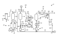
- FIG. 1 is a schematic depiction of an exemplary apparatus.
- an exemplary apparatus 10 for purifying natural gas can include a filter 20 , a plurality of filters 40 , a plurality of dryers 70 , a plurality of adsorbers 120 , a cooler 170 , a knockout drum 180 , a compressor 220 , another compressor 260 , another cooler 280 , and another knockout drum 290 .
- the apparatus 10 may include two dryers, namely a first dryer 80 and a second dryer 90 , and include three adsorbers, namely a first adsorber 130 , a second adsorber 140 , and a third adsorber 150 , additional dryers and/or adsorbers can be utilized.
- each adsorber 130 , 140 , and 150 undergoes three stages, namely an adsorption stage, a heating regeneration stage, and a cooling regeneration stage.
- process flow lines in the figures can be referred to, interchangeably, as, e.g., lines, pipes, feeds, streams, products, portions, or parts.
- a natural gas may be utilized as a feed 12 for the apparatus 10 .
- the feed 12 can include one or more C1-C6 hydrocarbons, preferably one or more C1-C2 hydrocarbons.
- the natural gas includes at least about 70%, by mole, of one or more C1 and C2 hydrocarbons, such as methane and ethane, and preferably at least about 90%, optimally about 95%, by mole, of methane.
- the natural gas may include nitrogen, carbon dioxide, and water.
- the natural gas may include no more than about 3%, by mole, preferably no more than about 2%, by mole, nitrogen; no more than about 2%, by mole, preferably no more than about 1.0%, by mole, more preferably no more than about 0.5%, by mole, and optimally no more than about 0.2%, by mole, carbon dioxide based on the moles of the natural gas; and no more than about 7,500 ppm, by volume, preferably no more than about 500 ppm, by volume, water, based on the volume of the natural gas.
- a natural gas may be obtained from natural sources, such as one or more wells, or synthetic sources such as one or more gasifiers or landfills.
- the feed 12 can be at a temperature of about 10-about 70° C., preferably about 10-about 40° C., and a pressure of about 600-about 12,000 kPa, preferably about 600-about 6,000 kPa.
- the pressure in the apparatus 10 can be relatively constant.
- the feed 12 can be provided to a filter 20 , which in this exemplary embodiment can be a coalescer 20 .
- the coalescer 20 can remove liquids from the feed 12 , which may be in a gas phase. Generally, the liquids exit the coalescer 20 as a condensate stream 22 .
- the remainder of the feed 12 can enter a line 24 and a portion, typically a substantial portion, may enter via a line 26 the third adsorber 150 of the plurality of adsorbers 120 and another portion may enter a line 14 , as hereinafter described.
- the third adsorber 150 can remove water and carbon dioxide from the feed entering the third adsorber 150 .
- the plurality of adsorbers 120 can contain any suitable adsorbent, or a combination of adsorbents to have the desired selectivity for water and carbon dioxide.
- Suitable adsorbents may include one or more crystalline molecular sieves, activated carbons, activated clays, silica gels, activated aluminas and combinations thereof, as disclosed in, e.g., U.S. Pat. No. 5,089,034.
- Molecular sieves include, for example, the various forms of silicoaluminophosphates and aluminophosphates, as disclosed in, e.g., U.S. Pat. Nos. 4,440,871 and 4,310,440.
- Zeolites that may be used as adsorbents include, chabazite, also referred to as zeolite D, clinoptilolite, erionite, faujasite, also referred to as zeolite X and zeolite Y, ferrierite, mordenite, zeolite A and zeolite P.
- Other zeolites that may be suitable for use may be those having a high silica content, i.e., those having silica to alumina ratios greater than 10.
- Exemplary zeolites are disclosed in, e.g., U.S. Pat. Nos. 4,061,724, 4,073,865, 4,775,396, and 4,935,580.
- binders can include one or more metal oxides, clays, silicas, aluminas, silica-aluminas, silica-zirconias, silica-thorias, silica-berylias, silica-titanias, silica-alumina-thorias, silica-alumina-zirconias, and a mixture thereof.
- Clay binders may be preferred, and exemplary clay binders may include attapulgite, kaolin, volclay, sepiolite, polygorskite, kaolinite, bentonite, montmorillonite, illite and chlorite.
- the third adsorber 150 can be operated at any suitable temperature and pressure, as disclosed above.
- the temperature during adsorption may be about 0-about 70° C., preferably about 15-about 50° C.
- the adsorption temperature is above the hydrocarbon dew point or the temperature of hydrate formation.
- the feed gas passes through the third adsorber 150 in generally a downflow direction.
- the purified natural gas product can exit the adsorber in a line 28 .
- the line 28 can be split into the lines 30 and 32 and the purified natural gas product can pass into a plurality of filters 40 including a first filter 42 and a second filter 44 for removing one or more particulates having a diameter greater than, e.g., about 10 microns, from the purified natural gas product.
- the filtered product gas can exit the lines 46 and 48 from respective filters 42 and 44 and be combined in a line 50 .
- the filters 42 and 44 can be operated alternatively with one filter removing particles and the other filter off-line.
- a part can be split in a line 52 , as hereinafter described, and another portion can be recovered as product in a line 54 .
- the product gas then can be in a suitable condition for subsequent processes, such as liquefaction.
- the portion of the filtered product gas provided at “A” via the line 52 can be combined with the recirculated regeneration gas from a line 224 , as hereinafter described, in a line 56 .
- the gas in the line 14 and the combined gases in the line 56 can be communicated to the heating regeneration circuit 60 for regenerating one or more adsorbers.
- the regeneration gas may include the purified natural gas product from the line 52 combined with the recirculated regeneration gas in the line 224 and combined with a portion of the feed gas from the line 14 .
- the regeneration may occur in the heating regeneration circuit 60 and in the cooling regeneration circuit 250 .
- the gas can be combined in a line 58 and enter a first dryer 80 of the plurality of dryers 70 .
- Each dryer 80 and 90 can, independently, have an adsorbent, such as a molecular sieve, as described above for the plurality of adsorbers 120 .
- the first dryer 80 can remove water from the combined gas to provide a gas suitable for regenerating.
- the first dryer 80 can reduce the amount of water to no more than about 10 ppm, by volume, preferably about 0.1 ppm, by volume, water based on the volume of gas in the line 82 .
- the gas can exit the first dryer 80 and enter the line 82 .
- the regeneration gas in the line 82 may enter the heater 100 using any suitable heat source, such as a furnace, an electric heater, a heat exchanger, or any combination thereof.
- a heat exchanger may use any suitable heating fluid stream 102 , such as pressurized steam, which may be followed by a subsequent heater, such as an electric heater.
- the heated gas can exit in a line 104 at a temperature of about 120-about 320° C., preferably about 120-about 300° C.
- the pressure is generally the same as described above.
- the gas can enter the first adsorber 130 of the plurality of adsorbers 120 , typically in another or opposite direction, e.g., upflow, as gas entering the first adsorber 130 in the adsorption stage.
- the gas regenerates the first adsorber 130 by incrementally raising the temperature over time of the first adsorber 130 typically until a predetermined temperature setpoint is reached. Once the desired raised temperature is reached, noncondensable contaminants, such as carbon dioxide and/or water, are released from the adsorbent. Other components may also be desorbed, such as hydrogen sulfide.
- a portion of the feed 12 can be utilized as a regeneration gas due to the elevated temperature of regeneration and the comparable high level of carbon dioxide circulating in the heating regeneration circuit 60 .
- the gas can enter into the adsorber 130 in a generally upflow direction.
- the gas including the contaminants may exit the first adsorber 130 and enter a line 160 to the cooler 170 , which can be a single air cooler 170 , optionally followed by another exchanger, such as a process or a cooling water exchanger.
- the air cooler 170 can lower the temperature of the gas exiting the adsorber to condense heavier hydrocarbons and water.
- the gas may exit the air cooler 170 and enter a line 172 to the knockout drum 180 .
- the knockout drum 180 can contain a demister 182 with a line 184 for draining condensate, typically including water, and a line 186 for removing gas.
- the gas in the line 186 can be split into a purge stream in a line 190 and the recirculating regeneration gas in a line 200 .
- the gas in the line 200 can be provided to a suction of a compressor 220 and discharged in a line 224 .
- the discharged gas can be combined with the feed gas in the line 14 and a filtered natural gas product in the line 52 to comprise the regeneration gas.
- the second adsorber 140 can undergo the cooling stage of regeneration.
- the second adsorber 140 can undergo the cooling stage to place the adsorber in condition for an adsorption stage, as depicted by third adsorber 150 .
- heated gas exiting the second adsorber 140 can enter a manifold by passing through a line 162 and pass an opened valve 164 to “B”.
- the gas can then pass through a line 252 and through an opened valve 254 .
- the gas can pass to a compressor 260 in the cooling regeneration circuit 250 .
- the cooling gas can pass through a line 262 to the second adsorber 140 .
- a hot fluid typically gas, can be present in the second adsorber 140 from the heating stage of regeneration.
- the gas may pass downward through the second adsorber 140 to a line 264 .
- the gas entering the second adsorber 140 can be in another or opposite direction, e.g., generally downflow, as compared to the heating stage.
- a valve 276 can be closed and a valve 266 may be open.
- the hot gas can pass through a line 268 into the second dryer 90 .
- the second dryer 90 is utilized to remove water from the purge gas during the heating stage of regeneration. Pushing the hot gas from the second adsorber 140 can desorb water from the sieve in the second dryer 90 into a line 270 .
- the gas can pass from a line 278 into a cooler 280 , which can be an air cooler 280 .
- the air cooler 280 may be followed by another exchanger, such as a process or a cooling water exchanger.
- the air cooler 280 can cool the gas that may pass into a line 282 to the knockout drum 290 .
- the knockout drum 290 can contain a demister 292 and provide a condensate, typically water, in a line 296 and gas passing to a line 294 .
- the gas can enter the line 258 into the compressor 260 and recirculated in a closed loop, minimizing material and energy losses.
- the cooled gas at a temperature of about 10-about 70° C., can pass from the second adsorber 140 to the second dryer 90 .
- the valve 266 can be closed and the valve 276 may be opened to bypass the second dryer 90 by allowing the gas to pass through a line 274 to speed the cooling of the second adsorber 140 and minimize energy consumption.
- the second adsorber 140 can be suitable for adsorption to produce a purified natural gas product.
- depictions can denote a plurality of such equipment of optionally varying type.
- a depicted air cooler can denote a plurality of coolers, such as air, process, and cooling water exchangers.
Abstract
One exemplary embodiment can be a process for purifying a natural gas by using first and second adsorbers. The process may include passing a feed including the natural gas through the first adsorber to obtain a purified natural gas product, regenerating the second adsorber in a heating stage, and regenerating the second adsorber in a cooling stage. The heating stage may include separating a portion of the feed comprised in a regeneration gas, passing the regeneration gas to a dryer for removing water, heating the regeneration gas with a heater after exiting the dryer, and passing the regeneration gas to the second adsorber to regenerate the second adsorber. The cooling stage may include expelling at initiation of cooling at least a part of a fluid present in the second adsorber to the dryer to desorb water from a molecular sieve in the dryer, and cooling the second adsorber by circulating the regeneration gas bypassing the heater.
Description
This process generally relates to purifying natural gas with one or more adsorbers and regenerating the same.
Natural gas, which can be obtained from off-shore sources, may be purified by adsorption with a molecular sieve. Typically, open loop regeneration is utilized due to the desire to adsorb more than one impurity, such as carbon dioxide. The use of close loop regeneration can be undesirable if other contaminants, such as water, are present due to excessive purge amounts that are generally required to remove these contaminants in the regeneration loop. Although closed loop regeneration has been proposed during the heating stage of adsorber regeneration, such closed loop systems can fail to provide sufficient flexibility for variations in contaminant levels in the natural gas. Generally, it is desirable to remove water and/or carbon dioxide from natural gas to levels that will not produce solids and/or hydrates during subsequent processing, such as liquefaction.
One exemplary embodiment can be a process for purifying a natural gas by using first and second adsorbers. The process may include passing a feed including the natural gas through the first adsorber to obtain a purified natural gas product, regenerating the second adsorber in a heating stage, and regenerating the second adsorber in a cooling stage. The heating stage may include separating a portion of the feed comprised in a regeneration gas, passing the regeneration gas to a dryer for removing water, heating the regeneration gas with a heater after exiting the dryer, and passing the regeneration gas to the second adsorber to regenerate the second adsorber. At an initiation of cooling, the cooling stage may include expelling at least a part of a fluid present in the second adsorber to the dryer to desorb water from an adsorbent in the dryer, and cooling the second adsorber by circulating the regeneration gas bypassing the heater.
Another exemplary embodiment may be a process of regenerating with a heating stage and a cooling stage for an adsorber purifying a natural gas stream. The process may include regenerating in the heating stage and the cooling stage. The heating stage can include passing a regeneration gas including a natural gas feed to a dryer for removing water, passing the dried regeneration gas to a heater, and passing the heated regeneration gas to an adsorber being regenerated. The cooling stage can include passing the regeneration gas at an initiation of cooling from the adsorber back to the dryer during regeneration to regenerate the dryer.
Yet another exemplary embodiment may be a process for a two-stage regeneration of an adsorber for removing one or more components from a natural gas. The process may include heating an adsorber with a regeneration gas including a natural gas feed in a first direction, and cooling the adsorber with the regeneration gas in another direction. Typically, an initial fluid present in the adsorber at an initiation of cooling is expelled to a dryer to regenerate a molecular sieve therein.
The embodiments disclosed herein provide a dryer utilized to remove water during a heating stage of regenerating an adsorber. During the heating stage, materials or components, such as carbon dioxide, water, and/or hydrogen sulfide, may be desorbed from the adsorber. Moreover, the dryer, in turn, may be regenerated during a cooling stage of regenerating by using fluid present in the adsorber at the initiation of cooling. As such, a closed loop regeneration can be used to minimize losses of product and/or feed natural gas used as a regeneration gas. A closed loop regeneration can also minimize energy losses by reducing the amount of make-up gas requiring compression during regeneration.
As used herein, the term “stream” can include various hydrocarbon molecules, such as straight-chain, branched, or cyclic alkanes, alkenes, alkadienes, and alkynes, and optionally other substances, such as gas, e.g., hydrogen, or impurities, such as heavy metals, and sulfur and nitrogen compounds. The stream can also include aromatic and non-aromatic hydrocarbons. Moreover, the hydrocarbon molecules may be abbreviated C1, C2, C3 . . . Cn where “n” represents the number of carbon atoms in the one or more hydrocarbon molecules. Furthermore, a superscript “+” or “−” may be used with an abbreviated one or more hydrocarbons notation, e.g., C3+ or C3−, which is inclusive of the abbreviated one or more hydrocarbons. As an example, the abbreviation “C3+” means one or more hydrocarbon molecules of three carbon atoms and/or more.
As used herein, the term “zone” can refer to an area including one or more equipment items and/or one or more sub-zones. Equipment items can include one or more reactors or reactor vessels, heaters, exchangers, pipes, pumps, compressors, and controllers.
Additionally, an equipment item, such as a reactor, dryer, or vessel, can further include one or more zones or sub-zones.
As used herein, the term “rich” can mean an amount of at least generally about 50%, and preferably about 70%, by mole, of a compound or class of compounds in a stream.
As used herein, the term “substantially” can mean an amount of at least generally about 80%, preferably about 90%, and optimally about 99%, by mole, of a compound or class of compounds in a stream.
As used herein, the terms “adsorbent” and “adsorber” include, respectively, an absorbent and an absorber, and relates, but is not limited to, processes such as absorption and/or adsorption.
As used herein, the term “gas” can include one or more gases, liquids, and/or solids in the form of a suspension, such as an aerosol.
As used herein, the term “purified natural gas product” may refer to a natural gas that has passed through an adsorber to remove, e.g., carbon dioxide and/or water, and includes a natural gas product that has undergone subsequent processing, such as filtering of particulates.
Referring to FIG. 1 , an exemplary apparatus 10 for purifying natural gas can include a filter 20, a plurality of filters 40, a plurality of dryers 70, a plurality of adsorbers 120, a cooler 170, a knockout drum 180, a compressor 220, another compressor 260, another cooler 280, and another knockout drum 290. Generally, at least some of the equipment can be included in a heating regeneration circuit 60 for a heating regeneration stage and a cooling regeneration circuit 250 for a cooling regeneration stage. Although the apparatus 10 may include two dryers, namely a first dryer 80 and a second dryer 90, and include three adsorbers, namely a first adsorber 130, a second adsorber 140, and a third adsorber 150, additional dryers and/or adsorbers can be utilized. Generally, each adsorber 130, 140, and 150 undergoes three stages, namely an adsorption stage, a heating regeneration stage, and a cooling regeneration stage. As depicted, process flow lines in the figures can be referred to, interchangeably, as, e.g., lines, pipes, feeds, streams, products, portions, or parts.
A natural gas may be utilized as a feed 12 for the apparatus 10. Typically, the feed 12 can include one or more C1-C6 hydrocarbons, preferably one or more C1-C2 hydrocarbons. Generally, the natural gas includes at least about 70%, by mole, of one or more C1 and C2 hydrocarbons, such as methane and ethane, and preferably at least about 90%, optimally about 95%, by mole, of methane. In addition to hydrocarbons, the natural gas may include nitrogen, carbon dioxide, and water. The natural gas may include no more than about 3%, by mole, preferably no more than about 2%, by mole, nitrogen; no more than about 2%, by mole, preferably no more than about 1.0%, by mole, more preferably no more than about 0.5%, by mole, and optimally no more than about 0.2%, by mole, carbon dioxide based on the moles of the natural gas; and no more than about 7,500 ppm, by volume, preferably no more than about 500 ppm, by volume, water, based on the volume of the natural gas. A natural gas may be obtained from natural sources, such as one or more wells, or synthetic sources such as one or more gasifiers or landfills.
Typically, the feed 12 can be at a temperature of about 10-about 70° C., preferably about 10-about 40° C., and a pressure of about 600-about 12,000 kPa, preferably about 600-about 6,000 kPa. Typically, the pressure in the apparatus 10 can be relatively constant.
The feed 12 can be provided to a filter 20, which in this exemplary embodiment can be a coalescer 20. The coalescer 20 can remove liquids from the feed 12, which may be in a gas phase. Generally, the liquids exit the coalescer 20 as a condensate stream 22. The remainder of the feed 12 can enter a line 24 and a portion, typically a substantial portion, may enter via a line 26 the third adsorber 150 of the plurality of adsorbers 120 and another portion may enter a line 14, as hereinafter described. The third adsorber 150 can remove water and carbon dioxide from the feed entering the third adsorber 150.
The plurality of adsorbers 120, such as the third adsorber 150, can contain any suitable adsorbent, or a combination of adsorbents to have the desired selectivity for water and carbon dioxide. Suitable adsorbents may include one or more crystalline molecular sieves, activated carbons, activated clays, silica gels, activated aluminas and combinations thereof, as disclosed in, e.g., U.S. Pat. No. 5,089,034. Molecular sieves include, for example, the various forms of silicoaluminophosphates and aluminophosphates, as disclosed in, e.g., U.S. Pat. Nos. 4,440,871 and 4,310,440.
Zeolites that may be used as adsorbents include, chabazite, also referred to as zeolite D, clinoptilolite, erionite, faujasite, also referred to as zeolite X and zeolite Y, ferrierite, mordenite, zeolite A and zeolite P. Other zeolites that may be suitable for use may be those having a high silica content, i.e., those having silica to alumina ratios greater than 10. Exemplary zeolites are disclosed in, e.g., U.S. Pat. Nos. 4,061,724, 4,073,865, 4,775,396, and 4,935,580.
Often, it is desirable to agglomerate a crystalline molecular sieve with a binder. Exemplary binders can include one or more metal oxides, clays, silicas, aluminas, silica-aluminas, silica-zirconias, silica-thorias, silica-berylias, silica-titanias, silica-alumina-thorias, silica-alumina-zirconias, and a mixture thereof. Clay binders may be preferred, and exemplary clay binders may include attapulgite, kaolin, volclay, sepiolite, polygorskite, kaolinite, bentonite, montmorillonite, illite and chlorite.
The third adsorber 150 can be operated at any suitable temperature and pressure, as disclosed above. The temperature during adsorption may be about 0-about 70° C., preferably about 15-about 50° C. Generally, the adsorption temperature is above the hydrocarbon dew point or the temperature of hydrate formation. Typically, the feed gas passes through the third adsorber 150 in generally a downflow direction.
The purified natural gas product can exit the adsorber in a line 28. The line 28 can be split into the lines 30 and 32 and the purified natural gas product can pass into a plurality of filters 40 including a first filter 42 and a second filter 44 for removing one or more particulates having a diameter greater than, e.g., about 10 microns, from the purified natural gas product. The filtered product gas can exit the lines 46 and 48 from respective filters 42 and 44 and be combined in a line 50. In another exemplary embodiment, the filters 42 and 44 can be operated alternatively with one filter removing particles and the other filter off-line. A part can be split in a line 52, as hereinafter described, and another portion can be recovered as product in a line 54. The product gas then can be in a suitable condition for subsequent processes, such as liquefaction.
The portion of the filtered product gas provided at “A” via the line 52 can be combined with the recirculated regeneration gas from a line 224, as hereinafter described, in a line 56. The gas in the line 14 and the combined gases in the line 56 can be communicated to the heating regeneration circuit 60 for regenerating one or more adsorbers. Thus, the regeneration gas may include the purified natural gas product from the line 52 combined with the recirculated regeneration gas in the line 224 and combined with a portion of the feed gas from the line 14. Particularly, the regeneration may occur in the heating regeneration circuit 60 and in the cooling regeneration circuit 250. Subsequently, the gas can be combined in a line 58 and enter a first dryer 80 of the plurality of dryers 70. Each dryer 80 and 90, can, independently, have an adsorbent, such as a molecular sieve, as described above for the plurality of adsorbers 120. The first dryer 80 can remove water from the combined gas to provide a gas suitable for regenerating. Generally, the first dryer 80 can reduce the amount of water to no more than about 10 ppm, by volume, preferably about 0.1 ppm, by volume, water based on the volume of gas in the line 82. Afterwards, the gas can exit the first dryer 80 and enter the line 82.
The regeneration gas in the line 82 may enter the heater 100 using any suitable heat source, such as a furnace, an electric heater, a heat exchanger, or any combination thereof. As an example, a heat exchanger may use any suitable heating fluid stream 102, such as pressurized steam, which may be followed by a subsequent heater, such as an electric heater. The heated gas can exit in a line 104 at a temperature of about 120-about 320° C., preferably about 120-about 300° C. The pressure is generally the same as described above.
The gas can enter the first adsorber 130 of the plurality of adsorbers 120, typically in another or opposite direction, e.g., upflow, as gas entering the first adsorber 130 in the adsorption stage. During the heating stage, the gas regenerates the first adsorber 130 by incrementally raising the temperature over time of the first adsorber 130 typically until a predetermined temperature setpoint is reached. Once the desired raised temperature is reached, noncondensable contaminants, such as carbon dioxide and/or water, are released from the adsorbent. Other components may also be desorbed, such as hydrogen sulfide. Generally, a portion of the feed 12 can be utilized as a regeneration gas due to the elevated temperature of regeneration and the comparable high level of carbon dioxide circulating in the heating regeneration circuit 60. Often, the gas can enter into the adsorber 130 in a generally upflow direction.
The gas including the contaminants may exit the first adsorber 130 and enter a line 160 to the cooler 170, which can be a single air cooler 170, optionally followed by another exchanger, such as a process or a cooling water exchanger. The air cooler 170 can lower the temperature of the gas exiting the adsorber to condense heavier hydrocarbons and water. The gas may exit the air cooler 170 and enter a line 172 to the knockout drum 180.
The knockout drum 180 can contain a demister 182 with a line 184 for draining condensate, typically including water, and a line 186 for removing gas. The gas in the line 186 can be split into a purge stream in a line 190 and the recirculating regeneration gas in a line 200. The gas in the line 200 can be provided to a suction of a compressor 220 and discharged in a line 224. As discussed above, the discharged gas can be combined with the feed gas in the line 14 and a filtered natural gas product in the line 52 to comprise the regeneration gas.
While the first adsorber 130 is undergoing the heating stage of regeneration, the second adsorber 140 can undergo the cooling stage of regeneration. Thus, once the second adsorber 140 undergoes the heating stage, it can undergo the cooling stage to place the adsorber in condition for an adsorption stage, as depicted by third adsorber 150.
At the initiation of cooling, heated gas exiting the second adsorber 140 can enter a manifold by passing through a line 162 and pass an opened valve 164 to “B”. The gas can then pass through a line 252 and through an opened valve 254. Next, the gas can pass to a compressor 260 in the cooling regeneration circuit 250. Once pressurized, the cooling gas can pass through a line 262 to the second adsorber 140. Initially, a hot fluid, typically gas, can be present in the second adsorber 140 from the heating stage of regeneration. The gas may pass downward through the second adsorber 140 to a line 264. In this exemplary embodiment, the gas entering the second adsorber 140 can be in another or opposite direction, e.g., generally downflow, as compared to the heating stage. Initially, a valve 276 can be closed and a valve 266 may be open. The hot gas can pass through a line 268 into the second dryer 90. Generally, the second dryer 90 is utilized to remove water from the purge gas during the heating stage of regeneration. Pushing the hot gas from the second adsorber 140 can desorb water from the sieve in the second dryer 90 into a line 270. Afterwards, the gas can pass from a line 278 into a cooler 280, which can be an air cooler 280. Optionally, the air cooler 280 may be followed by another exchanger, such as a process or a cooling water exchanger.
The air cooler 280 can cool the gas that may pass into a line 282 to the knockout drum 290. The knockout drum 290 can contain a demister 292 and provide a condensate, typically water, in a line 296 and gas passing to a line 294. The gas can enter the line 258 into the compressor 260 and recirculated in a closed loop, minimizing material and energy losses.
As the gas is circulated, the cooled gas at a temperature of about 10-about 70° C., can pass from the second adsorber 140 to the second dryer 90. Once the second dryer 90 is cooled, the valve 266 can be closed and the valve 276 may be opened to bypass the second dryer 90 by allowing the gas to pass through a line 274 to speed the cooling of the second adsorber 140 and minimize energy consumption. Once the cooling stage is completed, the second adsorber 140 can be suitable for adsorption to produce a purified natural gas product.
Although individual pieces of equipment, such as heaters, coolers, vessels, and rotating machines, are depicted, it should be understood that such depictions can denote a plurality of such equipment of optionally varying type. As an example, a depicted air cooler can denote a plurality of coolers, such as air, process, and cooling water exchangers.
Without further elaboration, it is believed that one skilled in the art can, using the preceding description, utilize the present invention to its fullest extent. The preceding preferred specific embodiments are, therefore, to be construed as merely illustrative, and not limitative of the remainder of the disclosure in any way whatsoever.
In the foregoing, all temperatures are set forth in degrees Celsius and, all parts and percentages are by weight, unless otherwise indicated.
From the foregoing description, one skilled in the art can easily ascertain the essential characteristics of this invention and, without departing from the spirit and scope thereof, can make various changes and modifications of the invention to adapt it to various usages and conditions.
Claims (17)
1. A process for purifying a natural gas by using first and second adsorbers, comprising:
A) passing a feed comprising the natural gas through the first adsorber to obtain a purified natural gas product;
B) regenerating the second adsorber in a heating stage, wherein the heating stage comprises:
1) separating a portion of the feed comprised in a regeneration gas;
2) passing the regeneration gas to a dryer for removing water;
3) heating the regeneration gas with a heater after exiting the dryer; and
4) passing the regeneration gas to the second adsorber to regenerate the second adsorber; and
C) regenerating the second adsorber in a cooling stage, wherein the cooling stage comprises:
1) expelling at initiation of cooling at least a part of a fluid present in the second adsorber to the dryer to desorb water from an adsorbent in the dryer; and
2) cooling the second adsorber by circulating the regeneration gas bypassing the heater.
2. The process according to claim 1 , wherein the natural gas comprises at least about 70%, by mole, of at least one of methane and ethane.
3. The process according to claim 1 , wherein the natural gas comprises at least about 95%, by mole, of methane.
4. The process according to claim 1 , wherein the natural gas comprises no more than about 2%, by mole, carbon dioxide.
5. The process according to claim 1 , wherein the natural gas comprises no more than about 0.5%, by mole, carbon dioxide.
6. The process according to claim 1 , wherein the natural gas comprises no more than about 7,500 ppm, by volume, water.
7. The process according to claim 1 , wherein the natural gas comprises no more than about 500 ppm, by volume, water.
8. The process according to claim 1 , wherein the regeneration gas comprises at least about 70%, by mole, of at least one of methane and ethane.
9. The process according to claim 1 , wherein the regeneration gas comprises at least about 95%, by mole, of methane.
10. The process according to claim 1 , wherein the regeneration gas comprises no more than about 2%, by mole, carbon dioxide.
11. The process according to claim 1 , wherein the regeneration gas comprises no more than about 0.5%, by mole, carbon dioxide.
12. The process according to claim 1 , wherein the first and second adsorbers contain an adsorbent.
13. The process according to claim 12 , wherein the adsorbent of the first and second adsorbers comprises a zeolite.
14. The process according to claim 1 , wherein the regeneration gas further comprises the purified natural gas product.
15. The process according to claim 1 , wherein the first adsorber operates at a temperature of about 10-about 70° C. and a pressure of about 600-about 12,000 kPa during adsorption.
16. The process according to claim 1 , wherein the second adsorber operates at a temperature of about 120-about 320° C. and a pressure of about 600-about 12,000 kPa during regeneration in the heating stage.
17. The process according to claim 1 , further comprising liquefying the purified natural gas product.
Priority Applications (7)
| Application Number | Priority Date | Filing Date | Title |
|---|---|---|---|
| US12/859,166 US8337593B2 (en) | 2010-08-18 | 2010-08-18 | Process for purifying natural gas and regenerating one or more adsorbers |
| BR112012031513-7A BR112012031513B1 (en) | 2010-08-18 | 2011-08-11 | PROCESS TO PURIFY A NATURAL GAS |
| RU2012153593/05A RU2525126C1 (en) | 2010-08-18 | 2011-08-11 | Method of natural gas cleaning and recovery of one or more adsorbers |
| CN201180029090.1A CN102958583B (en) | 2010-08-18 | 2011-08-11 | Process for purifying natural gas and regenerating one or more adsorbers |
| AU2011292270A AU2011292270B2 (en) | 2010-08-18 | 2011-08-11 | Process for purifying natural gas and regenerating one or more adsorbers |
| PCT/US2011/047318 WO2012024135A2 (en) | 2010-08-18 | 2011-08-11 | Process for purifying natural gas and regenerating one or more adsorbers |
| CA2801232A CA2801232C (en) | 2010-08-18 | 2011-08-11 | Process for purifying natural gas and regenerating one or more adsorbers |
Applications Claiming Priority (1)
| Application Number | Priority Date | Filing Date | Title |
|---|---|---|---|
| US12/859,166 US8337593B2 (en) | 2010-08-18 | 2010-08-18 | Process for purifying natural gas and regenerating one or more adsorbers |
Publications (2)
| Publication Number | Publication Date |
|---|---|
| US20120042689A1 US20120042689A1 (en) | 2012-02-23 |
| US8337593B2 true US8337593B2 (en) | 2012-12-25 |
Family
ID=45592980
Family Applications (1)
| Application Number | Title | Priority Date | Filing Date |
|---|---|---|---|
| US12/859,166 Active 2031-06-09 US8337593B2 (en) | 2010-08-18 | 2010-08-18 | Process for purifying natural gas and regenerating one or more adsorbers |
Country Status (7)
| Country | Link |
|---|---|
| US (1) | US8337593B2 (en) |
| CN (1) | CN102958583B (en) |
| AU (1) | AU2011292270B2 (en) |
| BR (1) | BR112012031513B1 (en) |
| CA (1) | CA2801232C (en) |
| RU (1) | RU2525126C1 (en) |
| WO (1) | WO2012024135A2 (en) |
Cited By (11)
| Publication number | Priority date | Publication date | Assignee | Title |
|---|---|---|---|---|
| RU2527922C1 (en) * | 2013-01-09 | 2014-09-10 | Открытое акционерное общество "Научно-исследовательский и проектный институт по переработке газа" ОАО "НИПИгазпереработка" | Installation for hydrocarbon gas preparation |
| US20160333275A1 (en) * | 2014-01-23 | 2016-11-17 | Dow Global Technologies Llc | Method to provide pipeline quality natural gas |
| US20160355743A1 (en) * | 2014-02-27 | 2016-12-08 | Dow Global Technologies Llc | Method for regenerating adsorbent media used for extracting natural gas liquids from natural gas |
| RU2622299C1 (en) * | 2016-08-23 | 2017-06-14 | Андрей Владиславович Курочкин | Installing gas desulphurization chelate |
| US10006698B2 (en) | 2015-07-27 | 2018-06-26 | GE Oil & Gas, Inc. | Using methane rejection to process a natural gas stream |
| US10029204B2 (en) | 2015-10-12 | 2018-07-24 | GE Oil & Gas, Inc. | Regenerating sieve material used for processing natural gas |
| RU2669269C2 (en) * | 2017-02-13 | 2018-10-09 | Общество С Ограниченной Ответственностью "Газпром Трансгаз Краснодар" | Method for regenerating the adsorbent of dehydration of natural gases |
| RU2768823C1 (en) * | 2021-02-16 | 2022-03-24 | Федеральное государственное казенное военное образовательное учреждение высшего образования "Военный учебно-научный центр Военно-воздушных сил "Военно-воздушная академия имени профессора Н.Е. Жуковского и Ю.А. Гагарина" (г. Воронеж) Министерства обороны Российской Федерации | Integrated air treatment unit |
| RU2768821C1 (en) * | 2021-02-09 | 2022-03-24 | Федеральное государственное казенное военное образовательное учреждение высшего образования "Военный учебно-научный центр Военно-воздушных сил "Военно-воздушная академия имени профессора Н.Е. Жуковского и Ю.А. Гагарина" (г. Воронеж) Министерства обороны Российской Федерации | Integrated air purification unit |
| RU2768922C1 (en) * | 2021-02-12 | 2022-03-25 | Федеральное государственное казенное военное образовательное учреждение высшего образования "Военный учебно-научный центр Военно-воздушных сил "Военно-воздушная академия имени профессора Н.Е. Жуковского и Ю.А. Гагарина" (г. Воронеж) Министерства обороны Российской Федерации | Integrated air purification unit |
| RU2788975C1 (en) * | 2022-05-06 | 2023-01-26 | Российская Федерация, от имени которой выступает Государственная корпорация по атомной энергии "Росатом" (Госкорпорация "Росатом") | Inert gas cleaning plant |
Families Citing this family (20)
| Publication number | Priority date | Publication date | Assignee | Title |
|---|---|---|---|---|
| US20110259044A1 (en) * | 2010-04-22 | 2011-10-27 | Baudat Ned P | Method and apparatus for producing liquefied natural gas |
| US20120000242A1 (en) * | 2010-04-22 | 2012-01-05 | Baudat Ned P | Method and apparatus for storing liquefied natural gas |
| CN103173256B (en) * | 2013-04-18 | 2014-06-25 | 四川科比科油气工程有限公司 | Natural gas multi-tower external cycle anaerobic regeneration dewatering method |
| US20170066988A1 (en) * | 2014-05-29 | 2017-03-09 | Dow Global Technologies Llc | Co-current regeneration process for adsorption media used for recovering condensable components from a gas stream |
| US20170066987A1 (en) * | 2014-05-29 | 2017-03-09 | Dow Global Technologies Llc | Improved adsorption process for recovering condensable components from a gas stream |
| CA2975171A1 (en) | 2015-01-27 | 2016-08-04 | Dow Global Technologies Llc | Separation of hydrocarbons using regenerable macroporous alkylene-bridged adsorbent |
| CA2974946C (en) | 2015-01-27 | 2023-01-10 | Dow Global Technologies Llc | Separation of nitrogen from hydrocarbon gas using pyrolyzed sulfonated macroporous ion exchange resin |
| US10076742B2 (en) * | 2015-02-19 | 2018-09-18 | ProSep, Inc. | Methods for regeneration of an organosilica media |
| US10081775B2 (en) | 2015-02-19 | 2018-09-25 | ProSep, Inc. | Methods for hydrocarbon dew point reduction using an organosilica media |
| US10105637B2 (en) * | 2015-09-25 | 2018-10-23 | Praxair Technology, Inc. | Adsorbent regeneration method |
| US10895417B2 (en) * | 2016-03-25 | 2021-01-19 | L'air Liquide Societe Anonyme Pour L'etude Et L'exploitation Des Procedes Georges Claude | Method for the production of air gases by the cryogenic separation of air with improved front end purification and air compression |
| RU2623001C1 (en) * | 2016-09-23 | 2017-06-21 | Андрей Владиславович Курочкин | Light fractions recovery unit |
| RU2648062C1 (en) * | 2016-11-28 | 2018-03-22 | Общество с ограниченной ответственностью "Научно-производственное объединение "НефтеХимПроект" | Device of adsorption drying gases |
| US10076721B2 (en) * | 2017-01-17 | 2018-09-18 | Chevron U.S.A. Inc. | Systems and methods for short loop regeneration of gas dehydration units |
| RU2650932C1 (en) * | 2017-10-31 | 2018-04-18 | Андрей Владиславович Курочкин | Installation of easy hydrocarbon fractions collection (options) |
| US10821394B2 (en) * | 2018-06-20 | 2020-11-03 | Uop Llc | Temperature swing adsorption process for heavy hydrocarbon removal |
| US11668524B2 (en) * | 2019-01-30 | 2023-06-06 | Exxonmobil Upstream Research Company | Methods for removal of moisture from LNG refrigerant |
| CN110106000B (en) * | 2019-05-13 | 2021-04-06 | 广东环球净化科技有限公司 | Natural gas drying equipment and process |
| CN110385018B (en) * | 2019-06-24 | 2021-11-26 | 四川天采科技有限责任公司 | Nondestructive drying method for post-circulation reaction gas in methane preparation of chloromethane |
| CN112280606B (en) * | 2020-12-29 | 2021-03-19 | 四川凌耘建科技有限公司 | Horizontal separation metering sledge and separation metering method thereof |
Citations (24)
| Publication number | Priority date | Publication date | Assignee | Title |
|---|---|---|---|---|
| US3594983A (en) | 1969-06-17 | 1971-07-27 | Process Services Inc | Gas-treating process and system |
| US3710547A (en) | 1970-03-11 | 1973-01-16 | Al E & C Ltd | Adsorption process for natural gas purification |
| US4061724A (en) | 1975-09-22 | 1977-12-06 | Union Carbide Corporation | Crystalline silica |
| US4073865A (en) | 1976-09-27 | 1978-02-14 | Union Carbide Corporation | Silica polymorph and process for preparing same |
| US4310440A (en) | 1980-07-07 | 1982-01-12 | Union Carbide Corporation | Crystalline metallophosphate compositions |
| US4440871A (en) | 1982-07-26 | 1984-04-03 | Union Carbide Corporation | Crystalline silicoaluminophosphates |
| US4484933A (en) | 1983-06-14 | 1984-11-27 | Union Carbide Corporation | Process for drying gas streams |
| US4567027A (en) | 1983-07-19 | 1986-01-28 | Metallurgie Hoboken-Overpelt | Process for defluorinating an acid sulphate solution |
| US4775396A (en) | 1987-11-05 | 1988-10-04 | Union Carbide Corporation | Selective adsorption of CO2 on zeolites |
| JPS63270522A (en) | 1987-04-30 | 1988-11-08 | Hitachi Ltd | Regenerating method for adsorption column |
| US4935580A (en) | 1988-06-14 | 1990-06-19 | Uop | Process for purification of hydrocarbons using metal exchanged clinoptilolite to remove carbon dioxide |
| US5089034A (en) | 1990-11-13 | 1992-02-18 | Uop | Process for purifying natural gas |
| US5551256A (en) | 1994-11-11 | 1996-09-03 | Linde Aktiengesellschaft | Process for liquefaction of natural gas |
| US5759236A (en) * | 1993-11-22 | 1998-06-02 | Engelhard Process Chemicals Gmbh | Energy-saving process for the separation of organic compounds from gases |
| US5779768A (en) * | 1996-03-19 | 1998-07-14 | Air Products And Chemicals, Inc. | Recovery of volatile organic compounds from gas streams |
| US5846295A (en) * | 1997-03-07 | 1998-12-08 | Air Products And Chemicals, Inc. | Temperature swing adsorption |
| US6099620A (en) * | 1998-06-17 | 2000-08-08 | Tekair, L.P. | Heat regenerated desiccant gas dryer and method of use |
| EP1027913A1 (en) * | 1998-07-07 | 2000-08-16 | Nippon Sanso Corporation | Method and apparatus for producing highly clean dry air |
| US6387337B1 (en) | 2000-07-14 | 2002-05-14 | The United States Of America As Represented By The United States Department Of Energy | Carbon dioxide capture process with regenerable sorbents |
| US7000332B1 (en) * | 2005-04-06 | 2006-02-21 | Pneumatech, Inc. | Pulse purge regenerative gas dryer |
| US7231784B2 (en) | 2004-10-13 | 2007-06-19 | Praxair Technology, Inc. | Method for producing liquefied natural gas |
| US7449049B2 (en) * | 2005-03-08 | 2008-11-11 | Institute Francais Du Petrole | Method of purifying a natural gas by mercaptan adsorption |
| US20100115839A1 (en) | 2008-11-10 | 2010-05-13 | Conocophillips Company | Multiple Fixed-Fluidized Beds for Contaminant Removal |
| US20110277496A1 (en) * | 2005-07-26 | 2011-11-17 | Northrop P Scott | Method of purifying hydrocarbons and regeneration of adsorbents used therein |
Family Cites Families (5)
| Publication number | Priority date | Publication date | Assignee | Title |
|---|---|---|---|---|
| SU1152628A1 (en) * | 1983-04-21 | 1985-04-30 | Научно-Исследовательский Институт Технологии Криогенного Машиностроения | Method of regeneration of adsorption units |
| US5855650A (en) * | 1997-09-09 | 1999-01-05 | Air Products And Chemicals, Inc. | Purification of gases using solid adsorbents |
| RU2241524C1 (en) * | 2003-03-11 | 2004-12-10 | Открытое акционерное общество криогенного машиностроения (ОАО "Криогенмаш") | Method and apparatus for integrated purification of gases |
| CN100536995C (en) * | 2006-07-11 | 2009-09-09 | 上海化工研究院 | Method and device for absorptive drying |
| RU2367505C1 (en) * | 2007-12-12 | 2009-09-20 | Открытое акционерное общество "Научно-исследовательский и проектный институт по переработке газа" (ОАО "НИПИгазпереработка") | Gas preparation unit |
-
2010
- 2010-08-18 US US12/859,166 patent/US8337593B2/en active Active
-
2011
- 2011-08-11 CN CN201180029090.1A patent/CN102958583B/en active Active
- 2011-08-11 BR BR112012031513-7A patent/BR112012031513B1/en active IP Right Grant
- 2011-08-11 AU AU2011292270A patent/AU2011292270B2/en active Active
- 2011-08-11 RU RU2012153593/05A patent/RU2525126C1/en active
- 2011-08-11 WO PCT/US2011/047318 patent/WO2012024135A2/en active Application Filing
- 2011-08-11 CA CA2801232A patent/CA2801232C/en active Active
Patent Citations (25)
| Publication number | Priority date | Publication date | Assignee | Title |
|---|---|---|---|---|
| US3594983A (en) | 1969-06-17 | 1971-07-27 | Process Services Inc | Gas-treating process and system |
| US3710547A (en) | 1970-03-11 | 1973-01-16 | Al E & C Ltd | Adsorption process for natural gas purification |
| US4061724A (en) | 1975-09-22 | 1977-12-06 | Union Carbide Corporation | Crystalline silica |
| US4073865A (en) | 1976-09-27 | 1978-02-14 | Union Carbide Corporation | Silica polymorph and process for preparing same |
| US4310440A (en) | 1980-07-07 | 1982-01-12 | Union Carbide Corporation | Crystalline metallophosphate compositions |
| US4440871A (en) | 1982-07-26 | 1984-04-03 | Union Carbide Corporation | Crystalline silicoaluminophosphates |
| US4484933A (en) | 1983-06-14 | 1984-11-27 | Union Carbide Corporation | Process for drying gas streams |
| US4567027A (en) | 1983-07-19 | 1986-01-28 | Metallurgie Hoboken-Overpelt | Process for defluorinating an acid sulphate solution |
| JPS63270522A (en) | 1987-04-30 | 1988-11-08 | Hitachi Ltd | Regenerating method for adsorption column |
| US4775396A (en) | 1987-11-05 | 1988-10-04 | Union Carbide Corporation | Selective adsorption of CO2 on zeolites |
| US4935580A (en) | 1988-06-14 | 1990-06-19 | Uop | Process for purification of hydrocarbons using metal exchanged clinoptilolite to remove carbon dioxide |
| US5089034A (en) | 1990-11-13 | 1992-02-18 | Uop | Process for purifying natural gas |
| US5759236A (en) * | 1993-11-22 | 1998-06-02 | Engelhard Process Chemicals Gmbh | Energy-saving process for the separation of organic compounds from gases |
| US5551256A (en) | 1994-11-11 | 1996-09-03 | Linde Aktiengesellschaft | Process for liquefaction of natural gas |
| US5779768A (en) * | 1996-03-19 | 1998-07-14 | Air Products And Chemicals, Inc. | Recovery of volatile organic compounds from gas streams |
| US5846295A (en) * | 1997-03-07 | 1998-12-08 | Air Products And Chemicals, Inc. | Temperature swing adsorption |
| US6099620A (en) * | 1998-06-17 | 2000-08-08 | Tekair, L.P. | Heat regenerated desiccant gas dryer and method of use |
| EP1027913A1 (en) * | 1998-07-07 | 2000-08-16 | Nippon Sanso Corporation | Method and apparatus for producing highly clean dry air |
| US6387337B1 (en) | 2000-07-14 | 2002-05-14 | The United States Of America As Represented By The United States Department Of Energy | Carbon dioxide capture process with regenerable sorbents |
| US7231784B2 (en) | 2004-10-13 | 2007-06-19 | Praxair Technology, Inc. | Method for producing liquefied natural gas |
| US7449049B2 (en) * | 2005-03-08 | 2008-11-11 | Institute Francais Du Petrole | Method of purifying a natural gas by mercaptan adsorption |
| US7000332B1 (en) * | 2005-04-06 | 2006-02-21 | Pneumatech, Inc. | Pulse purge regenerative gas dryer |
| WO2006107349A1 (en) | 2005-04-06 | 2006-10-12 | Pneumatech, Inc. | Pulse purge regenerative gas dryer |
| US20110277496A1 (en) * | 2005-07-26 | 2011-11-17 | Northrop P Scott | Method of purifying hydrocarbons and regeneration of adsorbents used therein |
| US20100115839A1 (en) | 2008-11-10 | 2010-05-13 | Conocophillips Company | Multiple Fixed-Fluidized Beds for Contaminant Removal |
Non-Patent Citations (1)
| Title |
|---|
| Diagram of an Adsorptive Process for Removal of Water and Carbon Dioxide publicly disclosed in the United States in 2008. A Dryer is Regenerated During Regeneration of an Adsorber in a Heating Stage. |
Cited By (14)
| Publication number | Priority date | Publication date | Assignee | Title |
|---|---|---|---|---|
| RU2527922C1 (en) * | 2013-01-09 | 2014-09-10 | Открытое акционерное общество "Научно-исследовательский и проектный институт по переработке газа" ОАО "НИПИгазпереработка" | Installation for hydrocarbon gas preparation |
| US20160333275A1 (en) * | 2014-01-23 | 2016-11-17 | Dow Global Technologies Llc | Method to provide pipeline quality natural gas |
| US9771522B2 (en) * | 2014-01-23 | 2017-09-26 | Dow Global Technologies Llc | Method to provide pipeline quality natural gas |
| US20160355743A1 (en) * | 2014-02-27 | 2016-12-08 | Dow Global Technologies Llc | Method for regenerating adsorbent media used for extracting natural gas liquids from natural gas |
| US9944872B2 (en) * | 2014-02-27 | 2018-04-17 | Dow Global Technologies Llc | Method for regenerating adsorbent media used for extracting natural gas liquids from natural gas |
| US10006698B2 (en) | 2015-07-27 | 2018-06-26 | GE Oil & Gas, Inc. | Using methane rejection to process a natural gas stream |
| US10029204B2 (en) | 2015-10-12 | 2018-07-24 | GE Oil & Gas, Inc. | Regenerating sieve material used for processing natural gas |
| RU2622299C1 (en) * | 2016-08-23 | 2017-06-14 | Андрей Владиславович Курочкин | Installing gas desulphurization chelate |
| RU2669269C2 (en) * | 2017-02-13 | 2018-10-09 | Общество С Ограниченной Ответственностью "Газпром Трансгаз Краснодар" | Method for regenerating the adsorbent of dehydration of natural gases |
| RU2768821C1 (en) * | 2021-02-09 | 2022-03-24 | Федеральное государственное казенное военное образовательное учреждение высшего образования "Военный учебно-научный центр Военно-воздушных сил "Военно-воздушная академия имени профессора Н.Е. Жуковского и Ю.А. Гагарина" (г. Воронеж) Министерства обороны Российской Федерации | Integrated air purification unit |
| RU2768922C1 (en) * | 2021-02-12 | 2022-03-25 | Федеральное государственное казенное военное образовательное учреждение высшего образования "Военный учебно-научный центр Военно-воздушных сил "Военно-воздушная академия имени профессора Н.Е. Жуковского и Ю.А. Гагарина" (г. Воронеж) Министерства обороны Российской Федерации | Integrated air purification unit |
| RU2768823C1 (en) * | 2021-02-16 | 2022-03-24 | Федеральное государственное казенное военное образовательное учреждение высшего образования "Военный учебно-научный центр Военно-воздушных сил "Военно-воздушная академия имени профессора Н.Е. Жуковского и Ю.А. Гагарина" (г. Воронеж) Министерства обороны Российской Федерации | Integrated air treatment unit |
| RU2788975C1 (en) * | 2022-05-06 | 2023-01-26 | Российская Федерация, от имени которой выступает Государственная корпорация по атомной энергии "Росатом" (Госкорпорация "Росатом") | Inert gas cleaning plant |
| RU2799068C1 (en) * | 2022-08-08 | 2023-07-03 | Российская Федерация, от имени которой выступает Государственная корпорация по атомной энергии "Росатом" (Госкорпорация "Росатом") | Method for purification of inert gases from oxygen |
Also Published As
| Publication number | Publication date |
|---|---|
| CN102958583A (en) | 2013-03-06 |
| BR112012031513A2 (en) | 2016-11-08 |
| RU2012153593A (en) | 2014-06-20 |
| WO2012024135A2 (en) | 2012-02-23 |
| CA2801232C (en) | 2016-01-05 |
| AU2011292270B2 (en) | 2013-12-19 |
| BR112012031513B1 (en) | 2020-03-17 |
| AU2011292270A1 (en) | 2013-01-10 |
| CN102958583B (en) | 2014-09-17 |
| RU2525126C1 (en) | 2014-08-10 |
| WO2012024135A3 (en) | 2012-05-31 |
| US20120042689A1 (en) | 2012-02-23 |
| CA2801232A1 (en) | 2012-02-23 |
Similar Documents
| Publication | Publication Date | Title |
|---|---|---|
| US8337593B2 (en) | Process for purifying natural gas and regenerating one or more adsorbers | |
| US6444012B1 (en) | Selective removal of nitrogen from natural gas by pressure swing adsorption | |
| EP2809752B1 (en) | Heavy hydrocarbon removal process | |
| US7449049B2 (en) | Method of purifying a natural gas by mercaptan adsorption | |
| US5415682A (en) | Process for the removal of volatile organic compounds from a fluid stream | |
| US8273153B2 (en) | Dry natural gas liquefaction method | |
| US5338450A (en) | Spiral-wound adsorber module | |
| AU2009211454B2 (en) | A process for regeneration of adsorbent beds | |
| US10399007B2 (en) | Temperature swing adsorption process and apparatus with closed loop regeneration | |
| RU2613914C1 (en) | Method for processing natural hydrocarbon gas | |
| AU2021261171A1 (en) | Process and apparatus for removing unwanted components from a gas mixture | |
| US5512082A (en) | Process for the removal of volatile organic compounds from a fluid stream | |
| CA2731185A1 (en) | Method for the removal of moisture in a gas stream | |
| US5503658A (en) | Process for the removal of volatile organic compounds from a fluid stream | |
| JPH0852304A (en) | Method of drying gaseous or liquid mixture using adsorbing device composed of alumina and molecular sieve | |
| WO2010064121A2 (en) | Process for gas separation | |
| RU2626354C1 (en) | Method of gas flow separation into single components or fractions | |
| RU2627849C1 (en) | Method for gas flow separation into single components or fractions | |
| Khattaby et al. | The Use Of New Adsorption Technology | |
| WO2012047548A2 (en) | Process for regeneration of adsorbent beds |
Legal Events
| Date | Code | Title | Description |
|---|---|---|---|
| AS | Assignment |
Owner name: UOP LLC, ILLINOIS Free format text: ASSIGNMENT OF ASSIGNORS INTEREST;ASSIGNORS:BRESLER, LEONID, MR.;FREEMAN, CEDRIC, MR.;CLARK, KEITH R., MR.;SIGNING DATES FROM 20100816 TO 20101008;REEL/FRAME:025128/0617 |
|
| STCF | Information on status: patent grant |
Free format text: PATENTED CASE |
|
| FPAY | Fee payment |
Year of fee payment: 4 |
|
| MAFP | Maintenance fee payment |
Free format text: PAYMENT OF MAINTENANCE FEE, 8TH YEAR, LARGE ENTITY (ORIGINAL EVENT CODE: M1552); ENTITY STATUS OF PATENT OWNER: LARGE ENTITY Year of fee payment: 8 |