US8339963B2 - Technique for end-to-end admission control of real-time packet flows - Google Patents
Technique for end-to-end admission control of real-time packet flows Download PDFInfo
- Publication number
- US8339963B2 US8339963B2 US10/799,704 US79970404A US8339963B2 US 8339963 B2 US8339963 B2 US 8339963B2 US 79970404 A US79970404 A US 79970404A US 8339963 B2 US8339963 B2 US 8339963B2
- Authority
- US
- United States
- Prior art keywords
- network
- packets
- voip
- bandwidth
- packet
- Prior art date
- Legal status (The legal status is an assumption and is not a legal conclusion. Google has not performed a legal analysis and makes no representation as to the accuracy of the status listed.)
- Expired - Fee Related, expires
Links
- 238000000034 method Methods 0.000 title abstract description 45
- 239000000523 sample Substances 0.000 claims abstract description 58
- 238000004891 communication Methods 0.000 description 20
- 230000011664 signaling Effects 0.000 description 13
- 230000004044 response Effects 0.000 description 12
- 238000010586 diagram Methods 0.000 description 10
- 239000008186 active pharmaceutical agent Substances 0.000 description 5
- 230000005540 biological transmission Effects 0.000 description 5
- 230000008569 process Effects 0.000 description 5
- 238000012986 modification Methods 0.000 description 3
- 230000004048 modification Effects 0.000 description 3
- 230000008901 benefit Effects 0.000 description 2
- 238000004590 computer program Methods 0.000 description 2
- 238000005516 engineering process Methods 0.000 description 2
- 238000007726 management method Methods 0.000 description 2
- 238000012545 processing Methods 0.000 description 2
- 238000013475 authorization Methods 0.000 description 1
- 239000000969 carrier Substances 0.000 description 1
- 230000001934 delay Effects 0.000 description 1
- 238000002592 echocardiography Methods 0.000 description 1
- 230000000694 effects Effects 0.000 description 1
- 238000011156 evaluation Methods 0.000 description 1
- 230000000977 initiatory effect Effects 0.000 description 1
- 238000012913 prioritisation Methods 0.000 description 1
- 230000001960 triggered effect Effects 0.000 description 1
Images


Classifications
-
- H—ELECTRICITY
- H04—ELECTRIC COMMUNICATION TECHNIQUE
- H04L—TRANSMISSION OF DIGITAL INFORMATION, e.g. TELEGRAPHIC COMMUNICATION
- H04L47/00—Traffic control in data switching networks
- H04L47/10—Flow control; Congestion control
- H04L47/11—Identifying congestion
- H04L47/115—Identifying congestion using a dedicated packet
-
- H—ELECTRICITY
- H04—ELECTRIC COMMUNICATION TECHNIQUE
- H04L—TRANSMISSION OF DIGITAL INFORMATION, e.g. TELEGRAPHIC COMMUNICATION
- H04L43/00—Arrangements for monitoring or testing data switching networks
-
- H—ELECTRICITY
- H04—ELECTRIC COMMUNICATION TECHNIQUE
- H04L—TRANSMISSION OF DIGITAL INFORMATION, e.g. TELEGRAPHIC COMMUNICATION
- H04L47/00—Traffic control in data switching networks
- H04L47/10—Flow control; Congestion control
- H04L47/12—Avoiding congestion; Recovering from congestion
-
- H—ELECTRICITY
- H04—ELECTRIC COMMUNICATION TECHNIQUE
- H04L—TRANSMISSION OF DIGITAL INFORMATION, e.g. TELEGRAPHIC COMMUNICATION
- H04L47/00—Traffic control in data switching networks
- H04L47/10—Flow control; Congestion control
- H04L47/15—Flow control; Congestion control in relation to multipoint traffic
-
- H—ELECTRICITY
- H04—ELECTRIC COMMUNICATION TECHNIQUE
- H04L—TRANSMISSION OF DIGITAL INFORMATION, e.g. TELEGRAPHIC COMMUNICATION
- H04L47/00—Traffic control in data switching networks
- H04L47/10—Flow control; Congestion control
- H04L47/18—End to end
-
- H—ELECTRICITY
- H04—ELECTRIC COMMUNICATION TECHNIQUE
- H04L—TRANSMISSION OF DIGITAL INFORMATION, e.g. TELEGRAPHIC COMMUNICATION
- H04L47/00—Traffic control in data switching networks
- H04L47/10—Flow control; Congestion control
- H04L47/24—Traffic characterised by specific attributes, e.g. priority or QoS
- H04L47/2408—Traffic characterised by specific attributes, e.g. priority or QoS for supporting different services, e.g. a differentiated services [DiffServ] type of service
-
- H—ELECTRICITY
- H04—ELECTRIC COMMUNICATION TECHNIQUE
- H04L—TRANSMISSION OF DIGITAL INFORMATION, e.g. TELEGRAPHIC COMMUNICATION
- H04L47/00—Traffic control in data switching networks
- H04L47/10—Flow control; Congestion control
- H04L47/24—Traffic characterised by specific attributes, e.g. priority or QoS
- H04L47/2416—Real-time traffic
-
- H—ELECTRICITY
- H04—ELECTRIC COMMUNICATION TECHNIQUE
- H04L—TRANSMISSION OF DIGITAL INFORMATION, e.g. TELEGRAPHIC COMMUNICATION
- H04L47/00—Traffic control in data switching networks
- H04L47/10—Flow control; Congestion control
- H04L47/24—Traffic characterised by specific attributes, e.g. priority or QoS
- H04L47/2441—Traffic characterised by specific attributes, e.g. priority or QoS relying on flow classification, e.g. using integrated services [IntServ]
-
- H—ELECTRICITY
- H04—ELECTRIC COMMUNICATION TECHNIQUE
- H04L—TRANSMISSION OF DIGITAL INFORMATION, e.g. TELEGRAPHIC COMMUNICATION
- H04L47/00—Traffic control in data switching networks
- H04L47/10—Flow control; Congestion control
- H04L47/26—Flow control; Congestion control using explicit feedback to the source, e.g. choke packets
-
- H—ELECTRICITY
- H04—ELECTRIC COMMUNICATION TECHNIQUE
- H04L—TRANSMISSION OF DIGITAL INFORMATION, e.g. TELEGRAPHIC COMMUNICATION
- H04L47/00—Traffic control in data switching networks
- H04L47/10—Flow control; Congestion control
- H04L47/29—Flow control; Congestion control using a combination of thresholds
-
- H—ELECTRICITY
- H04—ELECTRIC COMMUNICATION TECHNIQUE
- H04L—TRANSMISSION OF DIGITAL INFORMATION, e.g. TELEGRAPHIC COMMUNICATION
- H04L47/00—Traffic control in data switching networks
- H04L47/10—Flow control; Congestion control
- H04L47/31—Flow control; Congestion control by tagging of packets, e.g. using discard eligibility [DE] bits
-
- H—ELECTRICITY
- H04—ELECTRIC COMMUNICATION TECHNIQUE
- H04L—TRANSMISSION OF DIGITAL INFORMATION, e.g. TELEGRAPHIC COMMUNICATION
- H04L47/00—Traffic control in data switching networks
- H04L47/70—Admission control; Resource allocation
-
- H—ELECTRICITY
- H04—ELECTRIC COMMUNICATION TECHNIQUE
- H04L—TRANSMISSION OF DIGITAL INFORMATION, e.g. TELEGRAPHIC COMMUNICATION
- H04L47/00—Traffic control in data switching networks
- H04L47/70—Admission control; Resource allocation
- H04L47/76—Admission control; Resource allocation using dynamic resource allocation, e.g. in-call renegotiation requested by the user or requested by the network in response to changing network conditions
- H04L47/765—Admission control; Resource allocation using dynamic resource allocation, e.g. in-call renegotiation requested by the user or requested by the network in response to changing network conditions triggered by the end-points
-
- H—ELECTRICITY
- H04—ELECTRIC COMMUNICATION TECHNIQUE
- H04L—TRANSMISSION OF DIGITAL INFORMATION, e.g. TELEGRAPHIC COMMUNICATION
- H04L47/00—Traffic control in data switching networks
- H04L47/70—Admission control; Resource allocation
- H04L47/80—Actions related to the user profile or the type of traffic
- H04L47/801—Real time traffic
-
- H—ELECTRICITY
- H04—ELECTRIC COMMUNICATION TECHNIQUE
- H04L—TRANSMISSION OF DIGITAL INFORMATION, e.g. TELEGRAPHIC COMMUNICATION
- H04L47/00—Traffic control in data switching networks
- H04L47/70—Admission control; Resource allocation
- H04L47/82—Miscellaneous aspects
- H04L47/821—Prioritising resource allocation or reservation requests
-
- H—ELECTRICITY
- H04—ELECTRIC COMMUNICATION TECHNIQUE
- H04L—TRANSMISSION OF DIGITAL INFORMATION, e.g. TELEGRAPHIC COMMUNICATION
- H04L47/00—Traffic control in data switching networks
- H04L47/70—Admission control; Resource allocation
- H04L47/82—Miscellaneous aspects
- H04L47/822—Collecting or measuring resource availability data
-
- H—ELECTRICITY
- H04—ELECTRIC COMMUNICATION TECHNIQUE
- H04L—TRANSMISSION OF DIGITAL INFORMATION, e.g. TELEGRAPHIC COMMUNICATION
- H04L65/00—Network arrangements, protocols or services for supporting real-time applications in data packet communication
- H04L65/1066—Session management
-
- H—ELECTRICITY
- H04—ELECTRIC COMMUNICATION TECHNIQUE
- H04L—TRANSMISSION OF DIGITAL INFORMATION, e.g. TELEGRAPHIC COMMUNICATION
- H04L65/00—Network arrangements, protocols or services for supporting real-time applications in data packet communication
- H04L65/1066—Session management
- H04L65/1101—Session protocols
- H04L65/1104—Session initiation protocol [SIP]
-
- H—ELECTRICITY
- H04—ELECTRIC COMMUNICATION TECHNIQUE
- H04L—TRANSMISSION OF DIGITAL INFORMATION, e.g. TELEGRAPHIC COMMUNICATION
- H04L65/00—Network arrangements, protocols or services for supporting real-time applications in data packet communication
- H04L65/80—Responding to QoS
-
- H—ELECTRICITY
- H04—ELECTRIC COMMUNICATION TECHNIQUE
- H04L—TRANSMISSION OF DIGITAL INFORMATION, e.g. TELEGRAPHIC COMMUNICATION
- H04L43/00—Arrangements for monitoring or testing data switching networks
- H04L43/08—Monitoring or testing based on specific metrics, e.g. QoS, energy consumption or environmental parameters
- H04L43/0876—Network utilisation, e.g. volume of load or congestion level
- H04L43/0888—Throughput
-
- H—ELECTRICITY
- H04—ELECTRIC COMMUNICATION TECHNIQUE
- H04L—TRANSMISSION OF DIGITAL INFORMATION, e.g. TELEGRAPHIC COMMUNICATION
- H04L43/00—Arrangements for monitoring or testing data switching networks
- H04L43/10—Active monitoring, e.g. heartbeat, ping or trace-route
-
- H—ELECTRICITY
- H04—ELECTRIC COMMUNICATION TECHNIQUE
- H04L—TRANSMISSION OF DIGITAL INFORMATION, e.g. TELEGRAPHIC COMMUNICATION
- H04L43/00—Arrangements for monitoring or testing data switching networks
- H04L43/16—Threshold monitoring
Definitions
- the present invention relates generally to computer and communications network and, more particularly, to a technique for end-to-end admission control of real-time packet flows.
- VoIP voice over IP
- IP Internet Protocol
- VoIP offers the benefits of cost savings, open standards, multi-vendor interoperability, and integrated voice and data networks.
- Other real-time applications include, for example, video-conferencing, multimedia streaming and other multimedia services that require guaranteed quality of service (QoS), all of which may benefit from the technique for end-to-end admission control of real-time packet flows in accordance with the present invention.
- QoS quality of service
- VoIP Compared with traditional telephonic technology, VoIP also has its own difficulties.
- voice communications have been carried over the public switched telephone network (PSTN), a circuit-switched network that can ensure the quality of each call through dedicated bandwidth allocations. This consistently high level of voice quality is called “toll quality.”
- PSTN public switched telephone network
- IP networks are based on packet switching rather than circuit switching. Packet switching works well for data communications because it maximizes bandwidth utilization by allowing all users to dynamically share network bandwidth.
- traditional packet switching techniques do not adequately recognize the mixing of many different applications that have different traffic flow characteristics and performance requirements in one network or link. For example, real-time applications typically require minimum delay, low packet loss (or guaranteed bandwidth), whereas non-real-time application may be able to tolerate longer delays and recover from packet loss.
- video-conferencing and one-way multimedia streaming are real-time applications, the last two are more bandwidth-demanding.
- bandwidth management techniques such as prioritization to ensure that VoIP and other real-time multimedia applications get what they need.
- bandwidth management alone simply allocates bandwidth to critical applications at the expense of other applications and does not limit or prevent real-time applications from congesting a link to a point where the performance or quality of service offered for all real-time flows become unacceptable.
- Some providers or enterprises over-provision their network capacity so that application demands would never hit the bandwidth limit. This solution is not economical since it may require expensive upgrades to the carrier networks to meet the increasing peak demands for bandwidth. None of the existing solutions can prevent network congestion in an efficient and cost-effective manner and still provide high quality of service for real-time flows.
- the technique may be realized as a method for end-to-end admission control of real-time packet flows in a network having a plurality of network elements.
- the method may comprise transmitting at least one probe packet from a first network element to a second network element via a network path.
- the method may also comprise determining, at least one intermediate network element on the network path, at least one flow rate associated with a plurality of packets.
- the method may further comprise marking at least one predetermined bit in the at least one probe packet if the at least one flow rate is greater than a predetermined rate.
- the method may comprise controlling an admission of additional packets into the network based at least in part on the marking of the at least one predetermined bit in the at least one probe packet.
- the method may further comprise denying the admission of the additional packets into the network if the at least one predetermined bit in the at least one probe packet is marked.
- the method may further comprise transmitting at least one second probe packet from the second network element to the first network element via the network path, marking at least one second predetermined bit in the at least one second probe packet if the at least one flow rate is greater than a second predetermined rate, and controlling the admission of the additional packets into the network based at least in part on the marking of the at least one second predetermined bit in the at least one second probe packet.
- the first network element may echo information associated with the at least one second predetermined bit in the at least one second probe packet in a transmission to the network.
- the admission of the additional packets may be based at least in part on priorities or importance of the plurality of packets and the additional packets.
- the admission of the additional packets into the network may be controlled by an entity that controls the network.
- Information associated with the at least one predetermined bit in the at least one probe packet may be communicated to at least one of the first network element and the second network element.
- the at least one intermediate network element may be part of a bandwidth-limited path in the network.
- the plurality of packets comprise real-time packets.
- the plurality of packets may comprise Internet Protocol (IP) packets, including voice over IP packets, video over IP packets and real-time multimedia over IP packets.
- IP Internet Protocol
- the at least one predetermined bit may be part of a Differentiated Services field in an IP header of the at least one probe packet.
- the predetermined rate may be based on a network bandwidth allocated for the plurality of packets. And the predetermined rate may be raised to a value above the allocated network bandwidth for a predetermined period of time.
- the method may further comprise encoding the at least one predetermined bit in the at least one probe packet based at least in part on the at least one flow rate. And the method may further comprise discontinuing at least one packet flow based on the encoded at least one predetermined bit.
- the method may further comprise lowering a transmission rate between the first network element and the second network element or between any two network endpoints.
- the method may further comprise suspending packet transmissions without terminating the connection between the first network element and the second network element between any two network endpoints.
- the technique may be realized by at least one signal embodied in at least one carrier wave for transmitting a computer program of instructions configured to be readable by at least one processor for instructing the at least one processor to execute a computer process for performing the method as recited above.
- the technique may be realized by at least one processor readable carrier for storing a computer program of instructions configured to be readable by at least one processor for instructing the at least one processor to execute a computer process for performing the method as recited above.
- the technique may be realized by a system for end-to-end admission control of real-time packet flows in a network.
- the system may comprise a first network element that transmits at least one probe packet to a second network element via a network path.
- the system may also comprise at least one intermediate network element on the network path that determines at least one flow rate associated with a plurality of packets, and marks at least one predetermined bit in the at least one probe packet if the at least one flow rate is greater than a predetermined rate.
- the system may further comprise an admission control module that controls an admission of additional packets into the network based at least in part on an examination of the at least one predetermined bit in the at least one probe packet.
- FIG. 1 is a flow chart illustrating an exemplary method for end-to-end admission control of real-time packet flows in accordance with an embodiment of the present invention.
- FIG. 2 is a diagram illustrating the DiffServ Field in an IPv4 packet in accordance with an embodiment of the present invention.
- FIG. 3 is a block diagram illustrating an exemplary system for end-to-end admission control of real-time packet flows in accordance with an embodiment of the present invention.
- FIG. 4 is an exemplary bandwidth diagram in accordance with an embodiment of the present invention.
- FIG. 5 is another exemplary bandwidth diagram in accordance with an embodiment of the present invention.
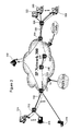
- FIG. 6 is a schematic illustration of an admission control scenario in accordance with an embodiment of the present invention.
- VoIP voice over IP
- IPv4 Internet Protocol
- IPv6 Internet Protocol
- FIG. 1 there is shown a flow chart illustrating an exemplary method for end-to-end admission control of packet flows in accordance with an embodiment of the present invention.
- a primary purpose of this exemplary method is to verify whether there is sufficient bandwidth along a specific network path connecting two network end terminals or VoIP clients.
- a first end terminal may initiate a call to a second end terminal (Terminal 2 ).
- the call setup may be started by using a number of standardized and/or customized signaling methods, such as Nortel Networks UniStim Interface Protocol (UNISTIM), Media Gateway Control Protocol (MGCP), Session Initiation Protocol (SIP), Automated System for Performance Evaluation of Networks (ASPEN), and the International Telecommunication Union (ITU) defined H.248 or H.323 standards can be used.
- Terminal 1 may send message(s) to a communication server in the network.
- the communication server may act as a proxy between Terminal 1 and Terminal 2 to coordinate and establish a real-time connection between them.
- step 102 additional messages may be exchanged between Terminal 1 and the communication server, in which process signaling could be used to obtain authentication, authorization and IP address of Terminal 2 , etc. After it is verified that call setup may continue, the call setup request may be forwarded to Terminal 2 .
- Terminal 2 may generate one or more probe packets (termed “REQUEST probe”) and transmit them down a specific network path towards Terminal 1 .
- the network path will be the same one that will carry VoIP payload packets once a connection is established.
- a “probe packet” may be a signaling packet, a control packet, or a payload packet that are sent along an end-to-end network path between two terminals or clients for the purpose of verifying bandwidth usage status.
- the probe packets may be of any type such as Real Time Protocol (RTP) type, ReSerVation Protocol (RSVP) type, or possibly a type currently contemplated by the Next Steps in Signaling (NSIS) Working Group, etc.
- RTP Real Time Protocol
- RSVP ReSerVation Protocol
- one or more selected network elements in the network path may meter the bandwidth usage at its node.
- the one or more selected network elements may be routers, switches, middle-boxes or servers through which the VoIP payload packets between the two VoIP end terminals flow.
- the network elements may be at selected nodes located in the bandwidth-limited portions of the network path.
- a bandwidth-limited path may include, for example, a “critical path” or “weakest link” on the network path connecting the two VoIP end terminals.
- the bandwidth usage may be metered at any intermediate nodes or all nodes.
- one or more network elements may be selected to meter the VoIP flows. For illustration purposes, an exemplary method with only one selected network element is described hereinafter.
- VoIP packet flows typically include two types of packets: signaling or control packets and payload packets.
- the signaling packets carry call-control messages that are used to set up and manage connections between VoIP clients.
- the payload packets carry the digitally encoded voice conversations.
- the signaling packets and payload packets may be marked with different Differentiated Services Code Point (DSCP) values.
- DSCP Differentiated Services Code Point
- the Differentiated Services (DiffServ or DS) model defines different treatment of packet flows.
- FIG. 2 is a diagram illustrating the DiffServ (or DS) Field in an IPv4 packet in accordance with an embodiment of the present invention.
- the six most significant bits (MSBs) of the DiffServ Field is known as Differentiated Services Code Point (DSCP).
- the two least significant bits are reserved as Explicit Congestion Notification (ECN) bits.
- ECN Explicit Congestion Notification
- EF Expedited Forwarding
- CS5 DSCP may be used for signaling, for example.
- the probe packets may be marked with EF DSCP.
- a traffic conditioner which is capable of metering EF or EF and CS5 packet flows and marking the ECN bit(s) of EF marked packets, may be implemented on the selected network element. For example, a sum of the VoIP and probe packets may be metered for a predetermined period of time. As a result, a flow rate may be determined as indication of the bandwidth status for packet flows having the same treatment (e.g., DSCP value being EF) at the selected network element. The flow rate may be measured on an ingress port or an egress port of the network element.
- step 108 it may be determined whether the flow rate is greater than a predetermined maximum rate “A.”
- the maximum rate “A” may be a predetermined portion of a total bandwidth allocated for VoIP applications. For example, if a network element or network path has 10 Mbps bandwidth, 1.5 Mbps of which is allocated for VoIP service (e.g., DSCP EF and CS5 packets), the maximum rate “A” may be 1.5 Mbps. Depending on the location of the network element and/or direction of the flow, the predetermined maximum rate may be different.
- the selected network element may, in step 110 , mark the ECN bit(s) of the DS Field in the IP headers in the probe packets and VoIP packets (e.g. all DSCP EF packets).
- the ECN bit(s) may be encoded by the network-element to convey a status of bandwidth usage in the VoIP path.
- Bit 7 of the DiffServ Field may be set to indicate that the VoIP path is congested with traffic.
- both ECN bits, i.e., Bit 6 and Bit 7 of the DiffServ Field may be encoded to indicate the level of congestion in the VoIP path, an example of which is shown in Table 1.
- the two ECN bits may have four binary values as indications of the traffic level or congestion level. What is shown in Table 1 is only an example and other encoding configuration may also be used.
- the method of marking or encoding ECN bit(s) may be extended to data fields other than the ECN bits or the DS Field.
- other predetermined bit(s) in the signaling packets may be marked or encoded to convey the bandwidth usage status.
- this method is limited to signaling packets.
- Other types of packets, such as control packets and payload packets may also serve the same or similar purpose.
- the predetermined bits may be in the IP header, UDP header, RTP header, or payload header of the packet that is used to convey the bandwidth usage status.
- the network element will not mark the ECN bit(s) in the REQUEST probe packets or the VoIP payload packets, though the ECN bits may be encoded if necessary.
- Terminal 1 may generate and send one or more probe packets (termed “RESPONSE probe”) back towards Terminal 2 .
- RESPONSE probe may be generated for each REQUEST probe packet received.
- Terminal 1 echoes the ECN bit settings in the REQUEST probe packets. That is, Terminal 1 may copy these settings in the RESPONSE probe packets.
- the one or more selected elements in the network path may again meter the bandwidth usage at their nodes.
- the flow rate of the sum of VoIP and probe packets may be metered.
- step 116 it may be determined whether the flow rate is greater than a predetermined maximum rate “B.” Depending on the location of the network element and/or direction of the flow, the predetermined maximum rate may be different. For example, the maximum rate on access links may be different from that on internal nodes. If the flow rate exceeds “B,” the selected network element may, in step 118 , mark or encode the ECN bit(s) of the DS Field in the IP headers of the RESPONSE probe packets and VoIP payload packets.
- Terminal 2 may echo or relay the ECN bit settings received into one or more messages it subsequently sends to the communication server.
- an admission control decision point in the communication server may examine the ECN bit settings carried in the one or more messages sent by Terminal 2 .
- the communication server may, in step 126 , stop the call setup process between Terminal 1 and Terminal 2 .
- the cause of failure may be sent to Terminal 1 , the call originating terminal.
- Emergency calls when present, may be admitted even if they exceed flow rate “A.” In that case, bandwidth may be temporarily borrowed from other applications to serve the emergency calls. In response to a shortage of assigned bandwidth, other actions that may also be taken.
- the transmission rate between Terminal 1 and Terminal 2 may be lowered to some extent (e.g., voice codec may be changed from G.711 to G.729, video encoding may be changed from 1.5 Mbps to 768 Kbps, etc.) If necessary, some transmissions may even be suspended without completely terminating the connections. Or, if necessary, some established connections may be torn down.
- call setup may be allowed to continue and a VoIP connection may be established between Terminal 1 and Terminal 2 .
- new emergency calls may still be allowed even when normal calls are denied access to the network.
- a network implementing the method for end-to-end admission control of packet flows may over-subscribe VoIP calls for a certain period of time without negative impact to an overall performance of the network.
- An exemplary bandwidth diagram illustrating temporary over-subscription is shown in FIG. 4 .
- a total bandwidth of the network is divided into two parts. One part is allocated for voice services such as VoIP and video-telephony. The rest of the bandwidth is allocated for other services or applications.
- a combination of normal calls and emergency calls may be allowed to use more bandwidth than what is allocated for voice services, up to a policing bandwidth.
- the network may have been servicing normal calls using all the voice services bandwidth. Then, a number of emergency calls may request setup. Instead of dropping ongoing normal calls to make space for emergency calls, the network may stop admitting additional normal calls and borrow a portion of the bandwidth from other applications to service the incoming emergency calls. Within approximately three minutes, which is the average length of normal calls, a number of voice calls will terminate normally, freeing up significant portion of bandwidth in the voice service or forwarding class. After then, emergency calls may be allowed to take up most or all of the bandwidth allocated to voice service.
- the end terminals may send probe packets to verify end-to-end bandwidth availability.
- the call originating end may send REQUEST probe first to call terminating end, and the call terminating end may then send a RESPONSE probe back to the call originating end or vise versa.
- both terminals can send probe packets towards each other at the same time.
- FIG. 5 is another exemplary bandwidth diagram in accordance with an embodiment of the present invention.
- a total bandwidth of the network is also divided into two parts.
- One part is reserved and guaranteed for VoIP services.
- the other part is allocated for other services or applications, part of which can be borrowed for VoIP over-subscription. If VoIP service is under-subscribed, its free bandwidth may be dynamically allocated for other services.
- a first traffic level (ECN encoded as “00”)
- all VoIP calls may be admitted.
- ECN encoded as “01” only VoIP calls above a certain priority level may be admitted and they take up a portion of bandwidth borrowed from other services.
- the higher priority calls are typically emergency calls or may be higher priority or importance calls as declared by the service being offered. Lower priority calls are denied access to the network. Once the voice traffic exceeds the second traffic level (ECN encoded as “10”), “preemptive termination” of calls will take effect. That is, connections for ongoing VoIP calls may be dropped starting from those having the lowest priority.
- ECN ECN encoded as “10”
- FIG. 3 is a block diagram illustrating an exemplary system for end-to-end admission control of packet flows in accordance with an embodiment of the present invention.
- the system may comprise a plurality of network elements (e.g., Router 304 , Router 306 , Router 310 and Router 312 ) located on or near the edge of an IP Network 300 .
- the system may also comprise a plurality of network elements (e.g., Router 334 and Router 336 ) located on a “critical path” (e.g., connection 338 ) between two VoIP clients.
- the system may further comprise a Communication Server 302 serving as an admission control decision point in this particular embodiment.
- Routers 304 , 306 , 310 , 312 , 334 and 336 serve as part of a connection path 328 between VoIP clients 308 and 314 . There are also other VoIP clients or end terminals ( 316 , 318 , 320 and 322 ) that are served by these routers. IP Network 300 may be also connected to a public switched telephone network (PSTN) 324 and a Time-Division Multiplexing (TDM) PBX (Private Branch Exchange) network 326 through their respective media gateways.
- PSTN public switched telephone network
- TDM Time-Division Multiplexing
- PBX Primary Branch Exchange
- VoIP client 314 may send signaling packets through access link 332 to Communication Server 302 .
- Communication Server 302 may process the call setup signaling request messages and send a call setup request message to VoIP client 308 .
- VoIP client 308 may be triggered to send one or more REQUEST probe packets towards VoIP client 314 .
- bandwidth usage along the path is measured and ECN bits may be set if measured bandwidth usage exceeds Rate “A.”
- Bandwidth usage status may be measured in upwards direction on access link 330 by either Router 304 or 306 or both, then on a critical path 338 towards the direction of IP client 314 , either by Router 334 or Router 336 or both, and in the downward direction on access link 332 by either Router 310 or 312 or both.
- VoIP client 314 may copy the ECN bit settings in these probe packets into its outgoing RESPONSE probe packets that are generated and sent back towards IP client 308 .
- bandwidth usage along the reverse path may be measured and ECN bits may be set if measured bandwidth usage exceeds Rate “B.”
- Bandwidth usage status may be measured in upwards direction on access link 332 by either Router 312 or 310 or both, then on critical path 338 towards the direction of IP client 308 , either by Router 334 or Router 336 or both, and in the downward direction on access link 330 by either Router 304 or 306 or both.
- IP client 308 Upon receiving RESPONSE probe packet, IP client 308 generates and sends a message that conveys the ECN bits setting as measured by the probe packets in both directions to Communication Server 302 .
- Communication Server 302 may examine the ECN bits status received.
- Communication Server 302 may become notified of a network congestion level for the new call being setup in both direction end-to-end. As a result, Communication Server 302 may discontinue call setup between the VoIP clients 314 and 308 , and send call-failure cause to VoIP client 314 or both.
- FIG. 6 there is schematically shown a SIP Client A at the call-originating end, an Edge Router I, a Communication Server 700 , an Edge Router E and a SIP Client B at the call-terminating end. There is also shown a plurality of packet streams.
- Client A may send an INVITE (Offer) message to Client B.
- Client B may then generate and send a REQUEST probe (e.g., RTP type packets) towards Client A.
- Client A may send a RESPONSE probe echoing the ECN bit settings in the REQUEST probe.
- Packets of both probes will flow along a specific network path which include edge routers (e.g., Edge Routers I and E) and core routers (e.g., Core Router M).
- edge routers e.g., Edge Routers I and E
- core routers e.g., Core Router M
- One or more of the routers may be selected to monitor the bandwidth usage and mark the ECN bits in the probe packets accordingly.
- the maximum allowed flow rates at the different routers may be same or different.
- Client B may copy the ECN bit settings from the probe packets into a NOTIFY message or any other messages that are sent to the Server 700 .
- Server 700 may examine the ECN bit settings carried in the NOTIFY message to determine the end-to-end bandwidth usage status in both directions.
- Server 700 may stop the call setup and send a 580 “Service Unavailable” message to Client A, the call originating terminal. Client A may acknowledge the end of call with an ACK message. If the ECN bits have not been marked, Server 700 may send a 200 “OK” message to Client B and the VoIP call setup will continue.
- the technique for end-to-end admission control of packet flows in accordance with the present invention as described above typically involves the processing of input data and the generation of output data to some extent.
- This input data processing and output data generation may be implemented in hardware or software.
- specific electronic components may be employed in a computer and/or communications network or similar or related circuitry for implementing the functions associated with end-to-end admission control of packet flows in accordance with the present invention as described above.
- one or more processors operating in accordance with stored instructions may implement the functions associated with end-to-end admission control of packet flows in accordance with the present invention as described above. If such is the case, it is within the scope of the present invention that such instructions may be stored on one or more processor readable carriers (e.g., a magnetic disk), or transmitted to one or more processors via one or more signals.
- processor readable carriers e.g., a magnetic disk
Abstract
Description
| TABLE 1 |
| Encoded ECN Bits for Different Levels of Congestion |
| Traffic Load Status in the | Bit | 6 | |
| Not Congested | 0 | 0 |
| 1st |
0 | 1 |
| (1st Level of Congestion) | ||
| 2nd |
1 | 0 |
| (2nd Level of Congestion) | ||
| 3rd |
1 | 1 |
| (3rd Level of Congestion) | ||
Claims (1)
Priority Applications (3)
| Application Number | Priority Date | Filing Date | Title |
|---|---|---|---|
| US10/799,704 US8339963B2 (en) | 2003-08-27 | 2004-03-15 | Technique for end-to-end admission control of real-time packet flows |
| US13/682,800 US8811182B2 (en) | 2003-08-27 | 2012-11-21 | Technique for end-to-end admission control of real-time packet flows |
| US14/335,330 US9106552B2 (en) | 2003-08-27 | 2014-07-18 | Technique for end-to-end admission control of real-time packet flows |
Applications Claiming Priority (2)
| Application Number | Priority Date | Filing Date | Title |
|---|---|---|---|
| US49793203P | 2003-08-27 | 2003-08-27 | |
| US10/799,704 US8339963B2 (en) | 2003-08-27 | 2004-03-15 | Technique for end-to-end admission control of real-time packet flows |
Related Child Applications (1)
| Application Number | Title | Priority Date | Filing Date |
|---|---|---|---|
| US13/682,800 Continuation US8811182B2 (en) | 2003-08-27 | 2012-11-21 | Technique for end-to-end admission control of real-time packet flows |
Publications (2)
| Publication Number | Publication Date |
|---|---|
| US20050047340A1 US20050047340A1 (en) | 2005-03-03 |
| US8339963B2 true US8339963B2 (en) | 2012-12-25 |
Family
ID=34221540
Family Applications (3)
| Application Number | Title | Priority Date | Filing Date |
|---|---|---|---|
| US10/799,704 Expired - Fee Related US8339963B2 (en) | 2003-08-27 | 2004-03-15 | Technique for end-to-end admission control of real-time packet flows |
| US13/682,800 Expired - Fee Related US8811182B2 (en) | 2003-08-27 | 2012-11-21 | Technique for end-to-end admission control of real-time packet flows |
| US14/335,330 Expired - Fee Related US9106552B2 (en) | 2003-08-27 | 2014-07-18 | Technique for end-to-end admission control of real-time packet flows |
Family Applications After (2)
| Application Number | Title | Priority Date | Filing Date |
|---|---|---|---|
| US13/682,800 Expired - Fee Related US8811182B2 (en) | 2003-08-27 | 2012-11-21 | Technique for end-to-end admission control of real-time packet flows |
| US14/335,330 Expired - Fee Related US9106552B2 (en) | 2003-08-27 | 2014-07-18 | Technique for end-to-end admission control of real-time packet flows |
Country Status (1)
| Country | Link |
|---|---|
| US (3) | US8339963B2 (en) |
Cited By (6)
| Publication number | Priority date | Publication date | Assignee | Title |
|---|---|---|---|---|
| US20060252429A1 (en) * | 2005-05-04 | 2006-11-09 | Lucent Technologies, Inc. | Flow-based call admission control for wireless communication systems |
| US20090327903A1 (en) * | 2006-07-06 | 2009-12-31 | Referentia Systems, Inc. | System and Method for Network Topology and Flow Visualization |
| US8484331B2 (en) * | 2010-11-01 | 2013-07-09 | Cisco Technology, Inc. | Real time protocol packet tunneling |
| US20180091431A1 (en) * | 2015-03-30 | 2018-03-29 | British Telecommunications Public Limited Company | Processing data items in a communications network |
| US10965576B2 (en) | 2016-02-05 | 2021-03-30 | Telefonaktiebolaget Lm Ericsson (Publ) | Method and apparatus for control plane to configure monitoring of differentiated service code point (DSCP) and explicit congestion notification (ECN) |
| US10965577B2 (en) * | 2016-02-05 | 2021-03-30 | Telefonaktiebolaget Lm Ericsson (Publ) | Method and apparatus for data plane to monitor differentiated services code point (DSCP) and explicit congestion notification (ECN) |
Families Citing this family (39)
| Publication number | Priority date | Publication date | Assignee | Title |
|---|---|---|---|---|
| US7516232B2 (en) | 2003-10-10 | 2009-04-07 | Microsoft Corporation | Media organization for distributed sending of media data |
| US7614071B2 (en) | 2003-10-10 | 2009-11-03 | Microsoft Corporation | Architecture for distributed sending of media data |
| US7545812B2 (en) * | 2003-10-10 | 2009-06-09 | Microsoft Corporation | Scheduling scheme for distributed sending of media data |
| US7443791B2 (en) * | 2003-10-10 | 2008-10-28 | Microsoft Corporation | Priority mechanism for distributed sending of media data |
| US7720983B2 (en) * | 2004-05-03 | 2010-05-18 | Microsoft Corporation | Fast startup for streaming media |
| US20060015639A1 (en) * | 2004-07-13 | 2006-01-19 | Taylor Benjamin F | Method for managing inter-zone bandwidth in a two-way messaging network |
| US7756031B2 (en) * | 2004-09-17 | 2010-07-13 | Holloway J Michael | Narrowband voice systems and methods |
| US8446826B2 (en) * | 2004-11-12 | 2013-05-21 | Telefonaktiebolaget Lm Ericsson (Publ) | Congestion handling in a packet switched network domain |
| CN100479374C (en) * | 2005-04-25 | 2009-04-15 | 华为技术有限公司 | Method for processing urgent business in network communication |
| US20080212575A1 (en) * | 2005-06-15 | 2008-09-04 | Lars Westberg | Codec Rate Adaptation as a Function of Air-Interface as Wel as Network in a Packet-Based Network |
| KR100781511B1 (en) * | 2005-06-29 | 2007-12-03 | 삼성전자주식회사 | Method and system of streaming service based on home network |
| KR101265954B1 (en) * | 2005-07-11 | 2013-05-23 | 더 트러스티이스 오브 콜롬비아 유니버시티 인 더 시티 오브 뉴욕 | Method and apparatus of performing tunnel signaling over ip tunneling path |
| KR101176383B1 (en) * | 2005-10-21 | 2012-08-23 | 더 트러스티이스 오브 콜롬비아 유니버시티 인 더 시티 오브 뉴욕 | Method and apparatus of performing tunnel signaling over ip tunneling path |
| KR101221594B1 (en) | 2005-10-24 | 2013-01-14 | 삼성전자주식회사 | Method and apparatus of performing tunnel signaling over ip tunneling path |
| US20070189467A1 (en) * | 2006-01-31 | 2007-08-16 | Marian Croak | Method and apparatus for bypassing overload control for emergency calls |
| JP4681480B2 (en) * | 2006-03-23 | 2011-05-11 | 富士通株式会社 | Traffic control device, traffic control system, and traffic control method |
| JP4768857B2 (en) * | 2006-11-10 | 2011-09-07 | テレフオンアクチーボラゲット エル エム エリクソン(パブル) | Edge nodes for network domains |
| US7760642B2 (en) | 2007-03-12 | 2010-07-20 | Citrix Systems, Inc. | Systems and methods for providing quality of service precedence in TCP congestion control |
| US7796510B2 (en) * | 2007-03-12 | 2010-09-14 | Citrix Systems, Inc. | Systems and methods for providing virtual fair queueing of network traffic |
| JP5104246B2 (en) * | 2007-11-21 | 2012-12-19 | 日本電気株式会社 | Communication system, subscriber accommodation device, traffic control method and program |
| US8149719B2 (en) | 2008-02-13 | 2012-04-03 | Embarq Holdings Company, Llc | System and method for marking live test packets |
| US8315179B2 (en) | 2008-02-19 | 2012-11-20 | Centurylink Intellectual Property Llc | System and method for authorizing threshold testing within a network |
| US8559320B2 (en) * | 2008-03-19 | 2013-10-15 | Avaya Inc. | Method and apparatus for measuring voice quality on a VoIP network |
| EP2230803A1 (en) * | 2009-03-16 | 2010-09-22 | BRITISH TELECOMMUNICATIONS public limited company | Path characterisation in networks |
| JP2010239288A (en) * | 2009-03-30 | 2010-10-21 | Sony Corp | Information processing device and method |
| US8717883B2 (en) * | 2010-12-17 | 2014-05-06 | Verizon Patent And Licensing Inc. | Media gateway health |
| FR2983375A1 (en) * | 2011-11-30 | 2013-05-31 | France Telecom | METHOD AND SERVER FOR MANAGING A REQUEST MADE BY A DEVICE ON A VOIP NETWORK CORE FOR RECORDING A CURRENT CONTACT ADDRESS OF THIS DEVICE |
| FR2987206A1 (en) * | 2012-02-16 | 2013-08-23 | France Telecom | TECHNIQUE FOR PROCESSING A DATA FLOW BETWEEN A SERVER AND A CLIENT ENTITY |
| US8964736B1 (en) * | 2012-11-27 | 2015-02-24 | Sprint Communications Company L.P. | RTP streaming with dynamic packet format modification |
| US20140153413A1 (en) * | 2012-11-30 | 2014-06-05 | Vonage Network, Llc | Systems and methods of routing ip telephony data packet communciations |
| TWI624183B (en) * | 2013-07-05 | 2018-05-11 | 元鼎音訊股份有限公司 | Method of processing telephone voice and computer program thereof |
| US9148814B2 (en) | 2013-10-28 | 2015-09-29 | At&T Intellectual Property I, L.P. | Probe mechanism for discovering explicit congestion notification data |
| US20150215413A1 (en) * | 2014-01-29 | 2015-07-30 | Qualcomm Incorporated | Modifying Presence Information of a Communication Device |
| US10015289B2 (en) * | 2014-08-12 | 2018-07-03 | Cisco Technology, Inc. | System and method for distribution of radio channel state and base station congestion state in a network environment |
| US9923836B1 (en) * | 2014-11-21 | 2018-03-20 | Sprint Spectrum L.P. | Systems and methods for configuring a delay based scheduler for an access node |
| WO2018029939A1 (en) * | 2016-08-12 | 2018-02-15 | パナソニック インテレクチュアル プロパティ コーポレーション オブ アメリカ | Terminal, base station, and communication method |
| GB2570676B (en) * | 2018-02-01 | 2021-04-21 | Openwave Mobility Inc | Signalling congestion status |
| CN110166366B (en) * | 2018-02-14 | 2023-02-28 | 华为技术有限公司 | Network congestion control method, device and system |
| WO2023091056A1 (en) * | 2021-11-19 | 2023-05-25 | Telefonaktiebolaget Lm Ericsson (Publ) | Congestion control monitoring |
Citations (3)
| Publication number | Priority date | Publication date | Assignee | Title |
|---|---|---|---|---|
| US20030107994A1 (en) * | 2000-05-18 | 2003-06-12 | Jacobs Richard J | Communications network |
| US6622172B1 (en) * | 1999-05-08 | 2003-09-16 | Kent Ridge Digital Labs | Dynamically delayed acknowledgement transmission system |
| US20040192312A1 (en) * | 2002-07-16 | 2004-09-30 | Jia-Ru Li | Communication system for voice and data with wireless TCP server |
Family Cites Families (5)
| Publication number | Priority date | Publication date | Assignee | Title |
|---|---|---|---|---|
| US6385168B1 (en) * | 1997-06-19 | 2002-05-07 | Alcatel Canada Inc. | Fair share bandwidth allocation algorithm and device |
| US6049541A (en) * | 1997-12-04 | 2000-04-11 | Alcatel Usa Sourcing, L.P. | Distributed telecommunications switching system and method |
| JP3556495B2 (en) * | 1998-12-15 | 2004-08-18 | 株式会社東芝 | Packet switch and packet switching method |
| US7342942B1 (en) * | 2001-02-07 | 2008-03-11 | Cortina Systems, Inc. | Multi-service segmentation and reassembly device that maintains only one reassembly context per active output port |
| US20070115814A1 (en) * | 2003-03-29 | 2007-05-24 | Regents Of The University Of California, The | Method and apparatus for improved data transmission |
-
2004
- 2004-03-15 US US10/799,704 patent/US8339963B2/en not_active Expired - Fee Related
-
2012
- 2012-11-21 US US13/682,800 patent/US8811182B2/en not_active Expired - Fee Related
-
2014
- 2014-07-18 US US14/335,330 patent/US9106552B2/en not_active Expired - Fee Related
Patent Citations (3)
| Publication number | Priority date | Publication date | Assignee | Title |
|---|---|---|---|---|
| US6622172B1 (en) * | 1999-05-08 | 2003-09-16 | Kent Ridge Digital Labs | Dynamically delayed acknowledgement transmission system |
| US20030107994A1 (en) * | 2000-05-18 | 2003-06-12 | Jacobs Richard J | Communications network |
| US20040192312A1 (en) * | 2002-07-16 | 2004-09-30 | Jia-Ru Li | Communication system for voice and data with wireless TCP server |
Non-Patent Citations (8)
| Title |
|---|
| An ECN Probe-Based Connection Acceptance Control , Jul. 2001, Tom Kelly. * |
| Naotaka Morita, "Measurable Forwarding: A New per-Hop Behavior (PHB)" TSV working group, Internet Draft, NTT Corporation, Oct. 2003, 1-19. |
| Naotaka Morita, "Verification Scenarios for Measurable Forwarding PHB (Per-Hop Behavior)" TSV working group, Internet Draft, NTT Corporation, Oct. 2003, 1-7. |
| Naotaka Morita, Gunnar Karlsson "Framework of Priority Promotion Scheme draft-morita-tsvwg-pps-00" TSVWG, Internet Draft, NTT Corporation, Jun. 23, 2003, 1-20. |
| Naotaka Morita, NTT Corporation, Gunnar Karlsson, KTH, "Framework of Priority Promotion Scheme" TSV working group, Internet Draft, Oct. 2003, 1-18. |
| Naotaka Morita, NTT Network Service Systems Labs., Gunnar Karlsson, KTH, "Framework of Priority Promotion Scheme (PPS) draft-morita-tsvwg-pps-00" TSVWG, Internet Draft, Jul. 18, 2003, 1-20. |
| Shunsuke Mori et al., "Priority Promotion Scheme (PPS)-An Autonomous and Distributed Admission Control for End-to-End Quality Service for Interactive Multimedia Services" NTT Technical Review, vol. 2 No. 10, Oct. 2004, 22-27. |
| Tom Kelly, "An ECN Probe-Based Connection Acceptance Control" Laboratory for Communications Engineering, Jul. 2001. |
Cited By (12)
| Publication number | Priority date | Publication date | Assignee | Title |
|---|---|---|---|---|
| US20060252429A1 (en) * | 2005-05-04 | 2006-11-09 | Lucent Technologies, Inc. | Flow-based call admission control for wireless communication systems |
| US9277455B2 (en) * | 2005-05-04 | 2016-03-01 | Alcatel Lucent | Flow-based call admission control for wireless communication systems |
| US20090327903A1 (en) * | 2006-07-06 | 2009-12-31 | Referentia Systems, Inc. | System and Method for Network Topology and Flow Visualization |
| US9003292B2 (en) * | 2006-07-06 | 2015-04-07 | LiveAction, Inc. | System and method for network topology and flow visualization |
| US9240930B2 (en) | 2006-07-06 | 2016-01-19 | LiveAction, Inc. | System for network flow visualization through network devices within network topology |
| US9246772B2 (en) | 2006-07-06 | 2016-01-26 | LiveAction, Inc. | System and method for network topology and flow visualization |
| US9350622B2 (en) | 2006-07-06 | 2016-05-24 | LiveAction, Inc. | Method and system for real-time visualization of network flow within network device |
| US8484331B2 (en) * | 2010-11-01 | 2013-07-09 | Cisco Technology, Inc. | Real time protocol packet tunneling |
| US20180091431A1 (en) * | 2015-03-30 | 2018-03-29 | British Telecommunications Public Limited Company | Processing data items in a communications network |
| US10523571B2 (en) * | 2015-03-30 | 2019-12-31 | British Telecommunications Public Limited Company | Processing data items in a communications network |
| US10965576B2 (en) | 2016-02-05 | 2021-03-30 | Telefonaktiebolaget Lm Ericsson (Publ) | Method and apparatus for control plane to configure monitoring of differentiated service code point (DSCP) and explicit congestion notification (ECN) |
| US10965577B2 (en) * | 2016-02-05 | 2021-03-30 | Telefonaktiebolaget Lm Ericsson (Publ) | Method and apparatus for data plane to monitor differentiated services code point (DSCP) and explicit congestion notification (ECN) |
Also Published As
| Publication number | Publication date |
|---|---|
| US20130077488A1 (en) | 2013-03-28 |
| US9106552B2 (en) | 2015-08-11 |
| US8811182B2 (en) | 2014-08-19 |
| US20140328174A1 (en) | 2014-11-06 |
| US20050047340A1 (en) | 2005-03-03 |
Similar Documents
| Publication | Publication Date | Title |
|---|---|---|
| US9106552B2 (en) | Technique for end-to-end admission control of real-time packet flows | |
| US8531948B2 (en) | Technique for admission control of packet flows | |
| US9172648B2 (en) | Flow admission control in an IP network | |
| US7251216B2 (en) | Methods and systems for configuring voice over internet protocol network quality of service | |
| US6449251B1 (en) | Packet mapper for dynamic data packet prioritization | |
| US8942243B2 (en) | Adaptive rate control in a communications system | |
| US7120122B1 (en) | System and method for diagnostic supervision of internet transmissions with quality of service control | |
| KR101508389B1 (en) | Communications Networks | |
| Goyal et al. | Integration of call signaling and resource management for IP telephony | |
| US20130322433A1 (en) | Method for setting up a communication link | |
| Cisco | Quality of Service for Voice over IP | |
| JP2004241835A (en) | Reception discrimination method to transfer quality assurance type data stream, closed ip network, and program thereof | |
| Christensen | Voice over IP solutions | |
| Prehofer et al. | Scalable resource management architecture for VoIP | |
| Rong et al. | Modeling and simulation of traffic aggregation based SIP over MPLS network architecture | |
| Houck et al. | A measurement-based admission control algorithm for VoIP | |
| Noro et al. | QoS support for VoIP traffic to prepare emergency | |
| Uzunalioglu et al. | Call admission control for voice over IP | |
| Sweeney et al. | Current and Future VoIP Quality of Service Techniques | |
| Molina et al. | Scalable and efficient QoS support for SIP‐signalled voice calls | |
| Luoma et al. | Quality of service for IP voice services: is it necessary? | |
| Alcuri et al. | Congestion Avoidance Using DYnamic COdec MAnagement: A Solution for ISP | |
| Ghazel et al. | Next Generation Networks Dimensioning with Improved and Guaranteed Quality of Service |
Legal Events
| Date | Code | Title | Description |
|---|---|---|---|
| AS | Assignment |
Owner name: NORTEL NETWORKS CORPORATION, QUEBEC Free format text: ASSIGNMENT OF ASSIGNORS INTEREST;ASSIGNORS:BABIARZ, JOZEF;CHAN, KWOK HO;REEL/FRAME:015100/0959 Effective date: 20040224 |
|
| AS | Assignment |
Owner name: NORTEL NETWORKS LIMITED, CANADA Free format text: CORRECTIVE ASSIGNMENT TO CORRECT THE CHANGE OF ASSIGNEE NAME FROM NORTEL NETWORKS CORPORATION TO NORTEL NETWORKS LIMITED PREVIOUSLY RECORDED ON REEL 015100 FRAME 0956;ASSIGNORS:BIBIARZ, JOZEF;CHAN, KWOK HO;REEL/FRAME:016682/0192 Effective date: 20040224 Owner name: NORTEL NETWORKS LIMITED, CANADA Free format text: CORRECTIVE ASSIGNMENT TO CORRECT THE CHANGE OF ASSIGNEE NAME FROM NORTEL NETWORKS CORPORATION TO NORTEL NETWORKS LIMITED PREVIOUSLY RECORDED ON REEL 015100 FRAME 0956. ASSIGNOR(S) HEREBY CONFIRMS THE CHANGE OF ASSIGNEE NAME FROM NORTEL NETWORKS CORPORATION TO NORTEL NETWORKS LIMITED;ASSIGNORS:BIBIARZ, JOZEF;CHAN, KWOK HO;REEL/FRAME:016682/0192 Effective date: 20040224 |
|
| AS | Assignment |
Owner name: ROCKSTAR BIDCO, LP, NEW YORK Free format text: ASSIGNMENT OF ASSIGNORS INTEREST;ASSIGNOR:NORTEL NETWORKS LIMITED;REEL/FRAME:027143/0717 Effective date: 20110729 |
|
| FEPP | Fee payment procedure |
Free format text: PAYOR NUMBER ASSIGNED (ORIGINAL EVENT CODE: ASPN); ENTITY STATUS OF PATENT OWNER: LARGE ENTITY |
|
| AS | Assignment |
Owner name: ROCKSTAR CONSORTIUM US LP, TEXAS Free format text: ASSIGNMENT OF ASSIGNORS INTEREST;ASSIGNOR:ROCKSTAR BIDCO, LP;REEL/FRAME:029235/0241 Effective date: 20120509 |
|
| FEPP | Fee payment procedure |
Free format text: PAYER NUMBER DE-ASSIGNED (ORIGINAL EVENT CODE: RMPN); ENTITY STATUS OF PATENT OWNER: LARGE ENTITY Free format text: PAYOR NUMBER ASSIGNED (ORIGINAL EVENT CODE: ASPN); ENTITY STATUS OF PATENT OWNER: LARGE ENTITY |
|
| AS | Assignment |
Owner name: CONSTELLATION TECHNOLOGIES LLC, TEXAS Free format text: ASSIGNMENT OF ASSIGNORS INTEREST;ASSIGNOR:ROCKSTAR CONSORTIUM US LP;REEL/FRAME:032162/0489 Effective date: 20131113 |
|
| AS | Assignment |
Owner name: RPX CLEARINGHOUSE LLC, CALIFORNIA Free format text: ASSIGNMENT OF ASSIGNORS INTEREST;ASSIGNORS:ROCKSTAR CONSORTIUM US LP;ROCKSTAR CONSORTIUM LLC;BOCKSTAR TECHNOLOGIES LLC;AND OTHERS;REEL/FRAME:034924/0779 Effective date: 20150128 |
|
| AS | Assignment |
Owner name: JPMORGAN CHASE BANK, N.A., AS COLLATERAL AGENT, IL Free format text: SECURITY AGREEMENT;ASSIGNORS:RPX CORPORATION;RPX CLEARINGHOUSE LLC;REEL/FRAME:038041/0001 Effective date: 20160226 |
|
| REMI | Maintenance fee reminder mailed | ||
| LAPS | Lapse for failure to pay maintenance fees | ||
| STCH | Information on status: patent discontinuation |
Free format text: PATENT EXPIRED DUE TO NONPAYMENT OF MAINTENANCE FEES UNDER 37 CFR 1.362 |
|
| FP | Lapsed due to failure to pay maintenance fee |
Effective date: 20161225 |
|
| AS | Assignment |
Owner name: RPX CORPORATION, CALIFORNIA Free format text: RELEASE (REEL 038041 / FRAME 0001);ASSIGNOR:JPMORGAN CHASE BANK, N.A.;REEL/FRAME:044970/0030 Effective date: 20171222 Owner name: RPX CLEARINGHOUSE LLC, CALIFORNIA Free format text: RELEASE (REEL 038041 / FRAME 0001);ASSIGNOR:JPMORGAN CHASE BANK, N.A.;REEL/FRAME:044970/0030 Effective date: 20171222 |