US8345745B2 - Method and apparatus for encoding and/or decoding moving pictures - Google Patents
Method and apparatus for encoding and/or decoding moving pictures Download PDFInfo
- Publication number
- US8345745B2 US8345745B2 US12/149,383 US14938308A US8345745B2 US 8345745 B2 US8345745 B2 US 8345745B2 US 14938308 A US14938308 A US 14938308A US 8345745 B2 US8345745 B2 US 8345745B2
- Authority
- US
- United States
- Prior art keywords
- block
- macroblock
- quantization weight
- intra
- inter
- Prior art date
- Legal status (The legal status is an assumption and is not a legal conclusion. Google has not performed a legal analysis and makes no representation as to the accuracy of the status listed.)
- Active, expires
Links
Images


Classifications
-
- H—ELECTRICITY
- H04—ELECTRIC COMMUNICATION TECHNIQUE
- H04N—PICTORIAL COMMUNICATION, e.g. TELEVISION
- H04N19/00—Methods or arrangements for coding, decoding, compressing or decompressing digital video signals
- H04N19/10—Methods or arrangements for coding, decoding, compressing or decompressing digital video signals using adaptive coding
- H04N19/134—Methods or arrangements for coding, decoding, compressing or decompressing digital video signals using adaptive coding characterised by the element, parameter or criterion affecting or controlling the adaptive coding
- H04N19/136—Incoming video signal characteristics or properties
-
- H—ELECTRICITY
- H04—ELECTRIC COMMUNICATION TECHNIQUE
- H04N—PICTORIAL COMMUNICATION, e.g. TELEVISION
- H04N19/00—Methods or arrangements for coding, decoding, compressing or decompressing digital video signals
- H04N19/10—Methods or arrangements for coding, decoding, compressing or decompressing digital video signals using adaptive coding
- H04N19/102—Methods or arrangements for coding, decoding, compressing or decompressing digital video signals using adaptive coding characterised by the element, parameter or selection affected or controlled by the adaptive coding
- H04N19/117—Filters, e.g. for pre-processing or post-processing
-
- H—ELECTRICITY
- H04—ELECTRIC COMMUNICATION TECHNIQUE
- H04N—PICTORIAL COMMUNICATION, e.g. TELEVISION
- H04N19/00—Methods or arrangements for coding, decoding, compressing or decompressing digital video signals
- H04N19/10—Methods or arrangements for coding, decoding, compressing or decompressing digital video signals using adaptive coding
- H04N19/102—Methods or arrangements for coding, decoding, compressing or decompressing digital video signals using adaptive coding characterised by the element, parameter or selection affected or controlled by the adaptive coding
- H04N19/124—Quantisation
- H04N19/126—Details of normalisation or weighting functions, e.g. normalisation matrices or variable uniform quantisers
-
- H—ELECTRICITY
- H04—ELECTRIC COMMUNICATION TECHNIQUE
- H04N—PICTORIAL COMMUNICATION, e.g. TELEVISION
- H04N19/00—Methods or arrangements for coding, decoding, compressing or decompressing digital video signals
- H04N19/10—Methods or arrangements for coding, decoding, compressing or decompressing digital video signals using adaptive coding
- H04N19/134—Methods or arrangements for coding, decoding, compressing or decompressing digital video signals using adaptive coding characterised by the element, parameter or criterion affecting or controlling the adaptive coding
- H04N19/136—Incoming video signal characteristics or properties
- H04N19/14—Coding unit complexity, e.g. amount of activity or edge presence estimation
-
- H—ELECTRICITY
- H04—ELECTRIC COMMUNICATION TECHNIQUE
- H04N—PICTORIAL COMMUNICATION, e.g. TELEVISION
- H04N19/00—Methods or arrangements for coding, decoding, compressing or decompressing digital video signals
- H04N19/10—Methods or arrangements for coding, decoding, compressing or decompressing digital video signals using adaptive coding
- H04N19/134—Methods or arrangements for coding, decoding, compressing or decompressing digital video signals using adaptive coding characterised by the element, parameter or criterion affecting or controlling the adaptive coding
- H04N19/157—Assigned coding mode, i.e. the coding mode being predefined or preselected to be further used for selection of another element or parameter
- H04N19/159—Prediction type, e.g. intra-frame, inter-frame or bidirectional frame prediction
-
- H—ELECTRICITY
- H04—ELECTRIC COMMUNICATION TECHNIQUE
- H04N—PICTORIAL COMMUNICATION, e.g. TELEVISION
- H04N19/00—Methods or arrangements for coding, decoding, compressing or decompressing digital video signals
- H04N19/10—Methods or arrangements for coding, decoding, compressing or decompressing digital video signals using adaptive coding
- H04N19/169—Methods or arrangements for coding, decoding, compressing or decompressing digital video signals using adaptive coding characterised by the coding unit, i.e. the structural portion or semantic portion of the video signal being the object or the subject of the adaptive coding
- H04N19/17—Methods or arrangements for coding, decoding, compressing or decompressing digital video signals using adaptive coding characterised by the coding unit, i.e. the structural portion or semantic portion of the video signal being the object or the subject of the adaptive coding the unit being an image region, e.g. an object
- H04N19/176—Methods or arrangements for coding, decoding, compressing or decompressing digital video signals using adaptive coding characterised by the coding unit, i.e. the structural portion or semantic portion of the video signal being the object or the subject of the adaptive coding the unit being an image region, e.g. an object the region being a block, e.g. a macroblock
-
- H—ELECTRICITY
- H04—ELECTRIC COMMUNICATION TECHNIQUE
- H04N—PICTORIAL COMMUNICATION, e.g. TELEVISION
- H04N19/00—Methods or arrangements for coding, decoding, compressing or decompressing digital video signals
- H04N19/10—Methods or arrangements for coding, decoding, compressing or decompressing digital video signals using adaptive coding
- H04N19/169—Methods or arrangements for coding, decoding, compressing or decompressing digital video signals using adaptive coding characterised by the coding unit, i.e. the structural portion or semantic portion of the video signal being the object or the subject of the adaptive coding
- H04N19/186—Methods or arrangements for coding, decoding, compressing or decompressing digital video signals using adaptive coding characterised by the coding unit, i.e. the structural portion or semantic portion of the video signal being the object or the subject of the adaptive coding the unit being a colour or a chrominance component
-
- H—ELECTRICITY
- H04—ELECTRIC COMMUNICATION TECHNIQUE
- H04N—PICTORIAL COMMUNICATION, e.g. TELEVISION
- H04N19/00—Methods or arrangements for coding, decoding, compressing or decompressing digital video signals
- H04N19/44—Decoders specially adapted therefor, e.g. video decoders which are asymmetric with respect to the encoder
-
- H—ELECTRICITY
- H04—ELECTRIC COMMUNICATION TECHNIQUE
- H04N—PICTORIAL COMMUNICATION, e.g. TELEVISION
- H04N19/00—Methods or arrangements for coding, decoding, compressing or decompressing digital video signals
- H04N19/46—Embedding additional information in the video signal during the compression process
-
- H—ELECTRICITY
- H04—ELECTRIC COMMUNICATION TECHNIQUE
- H04N—PICTORIAL COMMUNICATION, e.g. TELEVISION
- H04N19/00—Methods or arrangements for coding, decoding, compressing or decompressing digital video signals
- H04N19/60—Methods or arrangements for coding, decoding, compressing or decompressing digital video signals using transform coding
- H04N19/61—Methods or arrangements for coding, decoding, compressing or decompressing digital video signals using transform coding in combination with predictive coding
-
- H—ELECTRICITY
- H04—ELECTRIC COMMUNICATION TECHNIQUE
- H04N—PICTORIAL COMMUNICATION, e.g. TELEVISION
- H04N19/00—Methods or arrangements for coding, decoding, compressing or decompressing digital video signals
- H04N19/80—Details of filtering operations specially adapted for video compression, e.g. for pixel interpolation
-
- H—ELECTRICITY
- H04—ELECTRIC COMMUNICATION TECHNIQUE
- H04N—PICTORIAL COMMUNICATION, e.g. TELEVISION
- H04N19/00—Methods or arrangements for coding, decoding, compressing or decompressing digital video signals
- H04N19/85—Methods or arrangements for coding, decoding, compressing or decompressing digital video signals using pre-processing or post-processing specially adapted for video compression
Definitions
- the present invention relates to a method and apparatus for encoding and/or decoding moving pictures, and more particularly, to a method and an apparatus for encoding and/or decoding moving pictures which are capable of enhancing the efficiency of encoding moving pictures by adaptively selecting a quantization matrix in consideration of the characteristics of images input into a moving picture encoder.
- FIG. 1 is a block diagram of an encoding unit 120 for encoding moving pictures and a decoding unit 140 for decoding encoded moving pictures.
- the encoding unit 120 creates a bitstream encoded by a compression technique, and the decoding unit 140 restores original images from a bitstream input thereinto.
- a discrete cosine transform (DCT) unit 122 carries out a DCT operation on image data input thereinto in the unit of an 8 ⁇ 8 pixel block in order to remove spatial correlation from the input image data.
- a quantization unit (Q) 124 carries out highly efficient data loss compression by carrying out quantization on the input image data using a DCT coefficient obtained by the DCT unit 122 and representing the quantized data by several representative values.
- An inverse quantization unit (IQ) 126 inversely quantizes the quantized image data provided by the quantization unit 124 .
- An inverse discrete cosine transform (IDCT) unit 128 carries out an IDCT on the inversely quantized image data provided by the inverse quantization unit 126 .
- a frame memory unit 130 stores the IDCT'ed image data provided by the IDCT unit 128 on a frame-by-frame basis.
- a motion estimation and compensation unit (ME/MC) 132 estimates a motion vector (MV) for each macroblock and a sum of absolute difference (SAD), which correspond to a block matching error, by using the image data of a current frame inputted thereinto and the image data of a previous frame stored in the frame memory unit 130 .
- MV motion vector
- SAD sum of absolute difference
- VLC variable length coding unit
- the decoding unit 140 includes a variable length decoding unit (VLD) 142 , an inverse quantization unit 144 , an IDCT unit 146 , a frame memory unit 148 , and a motion estimation unit 150 .
- VLD variable length decoding unit
- U.S. Pat. No. 6,480,539 discloses an example of an apparatus for encoding moving pictures.
- a set-top box which receives an analog terrestrial broadcast program and then encodes and stores the received program by using a data compression method such as MPEG2 or MPEG4, has recently been developed.
- images arriving at a receiving terminal may be distorted due to channel noise. For example, an image may look as if white Gaussian noise were added thereto. If the image is compressed as it is, the efficiency of compressing the image may be very low due to the influence of the white Gaussian noise.
- a pretreatment filter is provided at an input port of an encoder.
- an additional calculation process for encoding moving pictures is needed.
- a quantization matrix is determined irrespective of the characteristics of an input image, and quantization is carried out on the input image by applying the quantization matrix to the input image on a picture-by-picture basis, in which case the efficiency of encoding the inputted image is low.
- the present invention provides a method and an apparatus for encoding and/or decoding moving pictures, which are capable of improving the efficiency and performance of compressing moving pictures.
- the present invention also provides a method and an apparatus for encoding and/or decoding moving pictures, which are capable of removing noise without increasing the number of calculations performed.
- a method of encoding moving pictures using a plurality of quantization matrices involves (a) selecting one of the plurality of quantization matrices in consideration of characteristics of an input image; (b) transforming the input image; and (c) quantizing the transformed input image using the selected quantization matrix.
- a method of decoding moving pictures using a plurality of quantization matrices involves (a) carrying out variable length decoding on encoded image data; (b) extracting index information that specifies one of the plurality of quantization matrices, classified according to characteristics of an input image, from the variable-length-decoded image data; (c) selecting one of the plurality of quantization matrices based on the extracted index information; and (d) inversely quantizing each macroblock of the variable-length-decoded image data using the selected quantization matrix.
- an apparatus for encoding moving pictures using a plurality of quantization matrices includes a quantization matrix determination unit that selects one of the plurality of quantization matrices for each macroblock in consideration of characteristics of an input image and generates index information indicating the selected quantization matrix for each macro block; a quantization matrix storage unit that stores a plurality of quantization matrices, which are classified according to the characteristics of the input image and outputs a quantization matrix for each macroblock according to the index information generated by the quantization matrix determination unit; an image transformation unit that transforms the input image; and a quantization unit that quantizes the transformed input image using the selected quantization matrix.
- an apparatus for decoding moving pictures using a plurality of quantization matrices includes a variable length decoding unit that receives an encoded image stream, carries out variable length decoding on the input image stream, and extracts index information that specifies one of the plurality of quantization matrices, which are classified according to characteristics of an input image, from each macroblock of the variable-length-decoded image stream; a quantization matrix storage unit that stores the plurality of quantization matrices, selects one of the plurality of quantization matrices based on the extracted index information, and outputs the selected quantization matrix; and an inverse quantization unit that inversely quantizes each macroblock of the variable-length-decoded image stream using the quantization matrix output from the quantization matrix storage unit.
- FIG. 1 is a block diagram of a conventional MPEG encoder and a conventional MPEG decoder
- FIG. 2 is a block diagram of an approximated generalized Wiener filter processing an image whose average is not 0;
- FIG. 3 is a block diagram of an approximated generalized Wiener filter processing an image whose average is not 0 in a DCT block;
- FIGS. 4A through 4C are block diagrams of different types of approximated generalized Wiener filters used for intra-block encoding
- FIG. 5 is a block diagram of a typical video encoder used for inter-block encoding
- FIG. 6 is a block diagram of an apparatus for encoding moving pictures according to an embodiment of the present invention.
- FIG. 7 is a block diagram of an apparatus for encoding moving pictures according to an embodiment of the present invention.
- FIG. 8 is a block diagram of an apparatus for decoding moving pictures according to an embodiment of the present invention.
- pre-treatment filtering is very important because it can increase the efficiency of encoding the moving pictures by removing noise from images. While a conventional pre-treatment filtering technique for removing noise from images is generally carried out in a spatial pixel block, in the present invention, a noise removal technique is carried out in a DCT block in an apparatus for encoding moving pictures.
- an approximated generalized Weiner filtering method is used for removing noise from images.
- Weiner filtering is realized by taking advantage of fast unitary transformation, such as a discrete cosine transform (DCT).
- DCT discrete cosine transform
- a filtering method other than the approximated generalized Weiner filtering method may be selectively used for carrying out filtering in a DCT block.
- FIG. 2 is a block diagram of an approximated generalized Weiner filter processing image data whose average is not 0.
- v represents an image block containing noise
- ⁇ represents a row-ordered column vector of a filtered image block. Since the average of the image block v is not 0, an average estimation unit 210 estimates an average ⁇ circumflex over (m) ⁇ of the image block v, and a subtraction unit 220 subtracts the estimated average ⁇ circumflex over (m) ⁇ from the image block v.
- An addition unit 240 adds the estimated average ⁇ circumflex over (m) ⁇ of the image block v to the filtered data and then outputs desirably filtered data ⁇ as a result of the addition.
- Equation (1) can be rearranged into Equation (2) below.
- Equation (2) Equation (1)
- Equation (3) Equation (3)
- Equation (4) ⁇ (k, l) represents normalized elements placed along a diagonal line of AL A* T , and ⁇ 2 represents a variance value of an original image y.
- ⁇ 2 cannot be known. Therefore, ⁇ 2 is substituted by a result of subtracting the noise variance value ⁇ n 2 from a variance value of z.
- Equation (3) approximated generalized Weiner filtering is carried out on an image block whose average is 0 by multiplying a two-dimensional DCT coefficient Z(k, l) by ⁇ tilde over (p) ⁇ (k, l). Once ⁇ (m, n) is determined, a final, filtered image is obtained by adding ⁇ circumflex over (m) ⁇ (m, n) to ⁇ (m, n).
- Equation (3) an image block filtered in the DCT block can be represented by Equation (6) below.
- Equation (7) F(k, l) in Equation (6) can be expressed by Equation (7) below.
- Equation (6) the entire filtering process can be simplified into a multiplication of F(k, l).
- Equation (7) shows that F(k, l) is determined by a signal-to-noise ratio (SNR), a covariance matrix, and an average matrix.
- SNR signal-to-noise ratio
- Equation (8) illustrates one of the simplest forms that the average matrix S(k, l) could take in the DCT block.
- an approximated generalized Weiner filtering process can be carried out on an image block whose average is not 0 by multiplying the image block with a DCT value.
- FIGS. 4A through 4C are block diagrams of different types of approximated generalized Weiner filters in an apparatus for encoding moving pictures. More specifically, FIGS. 4A through 4C illustrate the structure of an encoding apparatus that processes an intra block.
- FIGS. 4A and 4B describe that an intra block is encoded by carrying out filtering on the intra block in a DCT block and carrying out quantization and variable length coding (VLC) on the filtered intra block without performing an inverse DCT on the filtered intra block.
- FIGS. 4A and 4B describe that filtering is completed by multiplying the DCT coefficient by F(k, l).
- quantization is carried out by multiplying or dividing the DCT coefficient by a certain value with reference to a quantization table.
- the filtering carried out by multiplying the DCT coefficient by F(k, l) and the quantization carried out by multiplying the DCT coefficient by a certain value can be integrated into a single operation, as described in FIG. 4C .
- the concepts of the present invention can be directly applied to an occasion when an apparatus for encoding moving pictures processes an inter block, as long as the noise has been removed from the motion-compensated block information p(m, n).
- a covariance value ⁇ (k, l) is determined depending on whether an input image block is an inter block or an intra block. Therefore, F(k, l) of FIG. 5 may be varied depending on whether the input image block is an inter block or an intra block.
- Equation (9) a method of obtaining an estimated variance value of intra blocks or inter blocks, from each of which their average is subtracted, will be described in detail with reference to Equation (9) below.
- Supposing that S represents an N ⁇ N (where N 8) block from which an average of the corresponding block has already been subtracted, a variance matrix of the N ⁇ N block can be obtained using Equation (9).
- Equation (9) has been disclosed by W. Niehsen and M. Brunig in “Covariance Analysis of Motion-compensated Frame Differences”, IEEE Trans. Circ. Syst. for Video Technol., June 1999.
- An estimated variance value can be obtained by applying Equation (9) to a variety of experimental images.
- an original image block is an intra block
- an original image is divided into 8 ⁇ 8 blocks, and then a variance value of each of the 8 ⁇ 8 blocks is calculated.
- an estimated variance value is calculated by applying Equation (9) above to each image block that is determined as an inter block.
- Equation (7) ⁇ n 2 ⁇ 2 of Equation (7)
- ⁇ z 2 represents a variance value of each macroblock (MB).
- MB macroblock
- ⁇ z 2 is calculated on a macroblock-by-macroblock basis.
- 8 ⁇ 8 blocks in the same macroblock are supposed to have the same variance value. Therefore, there is no need to perform additional calculations to obtain a variance value of each of the 8 ⁇ 8 blocks.
- FIG. 6 is a block diagram of an apparatus for encoding moving pictures according to an embodiment of the present invention that encodes an input image in consideration of the characteristics of the input image.
- a level of noise contained in the input image is adaptively reflected in a quantization matrix.
- the apparatus of FIG. 6 includes a discrete cosine transfer unit 610 , a quantization unit (Q) 620 , a variable length coding unit (VLC) 670 , an inverse quantization unit (IQ) 630 , an inverse DCT unit (IDCT) 640 , a frame memory unit 650 , and a motion estimation and compensation unit 660 , which correspond to the DCT unit 122 , the quantization unit 124 , the VLC unit 134 , the inverse quantization unit 126 , the inverse DCT unit 128 , the frame memory 130 , and the motion estimation and compensation unit 132 , respectively, of the encoding unit 120 of FIG. 1 .
- the apparatus further includes a noise estimation unit 680 , a quantization weight matrix determination unit 692 , and a quantization weight matrix storage unit 694 .
- the DCT unit 610 Since the DCT unit 610 , the inverse DCT unit 640 , the frame memory unit 650 , and the motion estimation and compensation unit 660 serve the same functions as their respective counterparts of FIG. 1 , their description will not be repeated.
- the quantization weight matrix determination unit 692 determines a quantization weight matrix corresponding to a predetermined macroblock based on a noise variance value ⁇ n 2 received from the noise estimation unit 680 and the predetermined macroblock's variance value ⁇ z 2 received from the motion estimation and compensation unit 660 . Thereafter, the quantization weight matrix determination unit 692 sends index information corresponding to the determined quantization weight matrix to the quantization weight matrix storage unit 694 and the VLC unit 670 .
- F(k, l) is determined by Equation (7). Once F(k, l) is determined, the DCT coefficient V(k, l) of an 8 ⁇ 8 block is multiplied by F(k, l), and the result of the multiplication ⁇ (k, l) is divided by a predetermined quantization weight matrix during a quantization process.
- the apparatus of FIG. 6 integrates the process of multiplying F(k, l) by the DCT coefficient V(k, l) and the process of dividing ⁇ (k, l) by the quantization weight matrix into a single process and performs the single process.
- a location component of (k, I of a quantization weight matrix QT is represented by Q(k, l)
- a location of (k, l) in a new quantization weight matrix QT′ is Q(k, l)/F(k, l).
- a plurality of F matrices obtained using ⁇ n 2 and ⁇ z 2 are computed in advance, and then the new quantization weight matrix QT′ is then computed using the plurality of F matrices and then is stored in the quantization weight matrix storage unit 694 .
- five new quantization weight matrices obtained using ⁇ n 2 and ⁇ z 2 are stored in the quantization weight matrix storage unit 694 . Once ⁇ n 2 and ⁇ z 2 are determined,
- F(k, l) is determined by S(k, l), ⁇ (k, l), and
- Equation (8) ⁇ (k, l) is variably set depending on whether or not an input image is an inter block or an intra block. Therefore, there is only one variable left for determining F(k, l), i.e.,
- the provided quantization weight matrices QT′ are stored in the quantization weight matrix storage unit 694 .
- the quantization weight matrix determination unit 692 quantizes
- the result of the quantization is transmitted to the quantization weight matrix storage unit 692 and the VLC unit 670 as index information of a quantization matrix corresponding to the predetermined macroblock.
- quantization weight matrices stored in the quantization weight matrix storage unit 694 are classified into five different types according to
- ⁇ n 2 ⁇ 2 is carried out in five levels, and the index information of each of the five quantization weight matrices is set to 0, 1, 2, 3, or 4.
- T cutoff is used, as shown in Equation (11) below.
- ⁇ n 2 ⁇ 2 min ⁇ ( T cutoff , ⁇ n 2 ⁇ 2 ) ( 11 )
- T cutoff has a value between 1 and 2.
- the quantization weight matrix storage unit 694 transmits a quantization weight matrix corresponding to the index information received from the quantization weight matrix determination unit 692 to the quantization unit 620 and the inverse quantization unit 630 .
- the quantization unit 620 quantizes the predetermined macroblock using the quantization weight matrix received from the quantization weight matrix storage unit 694 .
- the inverse quantization unit 630 inversely quantizes the predetermined macroblock using the received quantization weight value.
- the VLC unit 670 carries out VLC on input image data quantized by the quantization unit 620 and inserts the index information of the quantization weight matrix received from the quantization weight matrix determination unit 692 into a macroblock header.
- the index information of the corresponding quantization weight matrix is inserted into the macroblock header and the macroblock header is transmitted. If there are ten quantization weight matrices stored in the quantization weight matrix storage unit 694 , then 4-bit data is required for each macroblock.
- Adjacent macroblocks are supposed to have similar image characteristics and there is supposedly a correlation among their index values. Therefore, a difference between an index value of one macroblock and an index value of an adjacent macroblock may be used as index information.
- the amount of index information to be transmitted can be considerably reduced in cases where a single quantization weight matrix is applied to an entire sequence.
- a plurality of quantization weight matrices stored in the quantization weight matrix storage unit 694 should also be stored in a decoding unit. It may also be possible to use a plurality of quantization weight matrices transmitted to the decoding unit on a picture-by-picture basis using a picture extension header or transmitted to the decoding unit on a sequence-by-sequence basis using a sequence extension header.
- noise removal has been described as being performed on a Y component of an input image block in a DCT block.
- the noise removal can also be applied to a U or V component of the input image block, in which case additional quantization weight matrices are required exclusively for the U and V components of the input image block.
- FIG. 7 is a block diagram of an apparatus for encoding moving pictures according to another preferred embodiment of the present invention that encodes an input image in consideration of the characteristics of the input image.
- the edge characteristics of each macroblock of the input image are taken into consideration in the present embodiment.
- an apparatus for encoding moving pictures includes a DCT unit 710 , a quantization unit 720 , a VLC unit 770 , an inverse quantization unit 730 , an inverse DCT unit 740 , a frame memory unit 750 , and a motion estimation and compensation unit 760 , which correspond to the DCT unit 122 , the quantization unit 124 , the VLC unit 134 , the inverse quantization unit 126 , the inverse DCT unit 128 , the frame memory 130 , and the motion estimation and compensation unit 132 , respectively, of the encoding unit 120 of FIG. 1 .
- the apparatus further includes a quantization matrix determination unit 780 and a quantization matrix storage unit 790 . Since the DCT unit 710 , the inverse DCT unit 740 , the frame memory unit 750 , the motion estimation and compensation unit 760 , and the VLC unit 770 serve the same functions as their respective counterparts of FIG. 1 , their description will not be repeated.
- the quantization matrix determination unit 780 selects an optimal quantization matrix for each macroblock in consideration of the characteristics of an input image and then transmits index information of the selected quantization matrix to the quantization matrix storage unit 790 and the VLC unit 770 .
- the quantization matrix determination unit 780 takes the edge characteristics of each macroblock into consideration as a benchmark for selecting one out of a predetermined number of quantization matrices.
- a predetermined macroblock of an input image is an intra block
- the size and direction of an edge in each pixel of the predetermined macroblock are computed using such an edge detector as a sobel operator.
- the sobel operation can be represented by Equation (12).
- H 1 [ - 1 0 1 - 2 0 2 - 1 0 1 ]
- H 2 [ - 1 - 2 - 1 0 0 2 1 2 1 ] ( 12 )
- the quantization matrix determination unit 780 calculates the magnitude of a vertical edge and the magnitude of a horizontal edge using Equation (12) above and calculates the intensity and direction of an edge of the predetermined macroblock using the magnitude of the vertical and horizontal edges. Thereafter, the quantization matrix determination unit 780 selects one from among a predetermined number of quantization matrices in consideration of the intensity and direction of the edge of the predetermined macroblock and encoding efficiency. In other words, in a case where the predetermined macro block includes a horizontal or vertical edge, the quantization matrix determination unit 780 selects a quantization matrix that can enable quantization in full consideration of the horizontal or vertical edge of the predetermined macro block.
- the intensity and direction of an edge included in the predetermined macroblock can also be obtained using such an edge detector as a sobel operator.
- a sobel detector is used for computing the intensity and direction of an edge included in the predetermined macroblock.
- a spatial filter such as a differential filter or a Robert's filter, can also be used for computing the intensity and direction of the edge included in the predetermined macroblock.
- a quantization matrix is selected in consideration of the edge characteristics of the predetermined macroblock.
- other characteristics of the predetermined macroblock that can affect encoding efficiency or the quality of an output image can be taken into consideration in adaptively selecting an optimal quantization matrix for the predetermined macroblock.
- the quantization matrix storage unit 790 selects a quantization matrix based on the index information received from the quantization matrix determination unit 780 and transmits the selected quantization matrix to the quantization unit 720 and the inverse quantization unit 730 .
- the quantization unit 720 carries out quantization using the quantization matrix received from the quantization matrix storage unit 790 .
- the inverse quantization unit 730 carries out inverse quantization using the quantization matrix received from the quantization matrix storage unit 790 .
- the VLC unit 770 carries out VLC on quantized input image data, received from the quantization unit 720 , and index information of a quantization matrix corresponding to the predetermined macroblock, received from the quantization weight matrix determination unit 780 .
- the index information is inserted into a macroblock header.
- index information of a quantization weight matrix corresponding to a predetermined macroblock is inserted into a header of the predetermined macroblock and then transmitted.
- a difference between an index value of one macroblock and an index value of an adjacent macroblock may be used as index information.
- a plurality of quantization weight matrices stored in the quantization matrix storage unit 790 are also stored in a decoding unit.
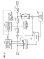
- FIG. 8 is a block diagram of an apparatus for decoding moving pictures according to an embodiment of the present invention.
- the apparatus includes a variable length decoding unit 810 , an inverse quantization unit 820 , an inverse DCT unit 830 , a frame memory unit 840 , and a motion compensation unit 850 , which correspond to the variable length decoding unit 142 , the inverse quantization unit 144 , the inverse DCT unit 146 , the frame memory unit 148 , and the motion compensation unit 150 , respectively, of the decoding unit 140 of FIG. 1 .
- the apparatus further includes a quantization weight matrix storage unit 860 .
- the inverse DCT unit 830 , the frame memory unit 840 , and the motion compensation unit 850 serve the same functions as their respective counterparts of FIG. 1 , and thus their description will not be repeated here.
- the variable length decoding unit 810 carries out variable length decoding on an input stream, extracts index information of a quantization weight matrix corresponding to a predetermined macroblock of the input stream from a header of the predetermined macroblock, and outputs the extracted index information to the quantization weight matrix storage unit 860 .
- the quantization weight matrix storage unit 860 outputs a quantization weight matrix corresponding to the index information received from the variable length decoding unit 810 to the inverse quantization unit 820 .
- the quantization weight matrix storage unit 860 stores a plurality of quantization weight matrices, which are classified according to the characteristics of an input image processed by an encoding unit, for example, a noise variance value as a ratio between an input image variance value and the edge characteristics of the input image.
- the plurality of quantization weight matrices stored in the quantization weight matrix storage unit 860 can be transmitted on a picture-by-picture basis using a picture extension header or transmitted to the decoding unit on a sequence-by-sequence basis using a sequence extension header.
- the plurality of quantization weight matrices are transmitted from the variable length decoding unit 810 to the quantization weight matrix storage unit 860 , as marked by a dotted line in FIG. 8 .
- the present invention can be applied to different types of methods and apparatuses for encoding and/or decoding moving pictures, such as MPEG-1, MPEG-2, or MPEG-4.
- the present invention can be realized as computer-readable codes written on a computer-readable recording medium.
- the computer-readable recording medium includes any type of recording device on which data can be written in a computer-readable manner.
- the computer-readable recording medium includes ROM, RAM, CD-ROM, a magnetic tape, a hard disk, a floppy disk, flash memory, an optical data storage, and a carrier wave (such as data transmission through the Internet).
- the computer-readable recording medium can be distributed over a plurality of computer systems which are connected to one another in a network sort of way so that computer-readable codes are stored on the computer-readable recording medium in a decentralized manner.
- a quantization matrix is adaptively applied to each macroblock of an input image in consideration of the characteristics of the input image.
Abstract
A method of encoding moving pictures using a plurality of quantization matrices. The method involves selecting one of the plurality of quantization matrices in consideration of an at least one characteristics of an input image; transforming the input image; and quantizing the transformed input image using the selected quantization matrix.
Description
This application is a continuation of application Ser. No. 11/249,389 filed on Oct. 14, 2005, which is a continuation of application Ser. No. 10/755,671 filed Jan. 13, 2004, which claims the priority of Korean Patent Application No. 2003-2371, filed on Jan. 14, 2003, in the Korean Intellectual Property Office, the disclosure of which is incorporated herein by reference.
1. Field of the Invention
The present invention relates to a method and apparatus for encoding and/or decoding moving pictures, and more particularly, to a method and an apparatus for encoding and/or decoding moving pictures which are capable of enhancing the efficiency of encoding moving pictures by adaptively selecting a quantization matrix in consideration of the characteristics of images input into a moving picture encoder.
2. Description of the Related Art
In order to provide a video-on-demand (VOD) service or to enable a moving picture communication, the encoding unit 120 creates a bitstream encoded by a compression technique, and the decoding unit 140 restores original images from a bitstream input thereinto.
A discrete cosine transform (DCT) unit 122 carries out a DCT operation on image data input thereinto in the unit of an 8×8 pixel block in order to remove spatial correlation from the input image data. A quantization unit (Q) 124 carries out highly efficient data loss compression by carrying out quantization on the input image data using a DCT coefficient obtained by the DCT unit 122 and representing the quantized data by several representative values.
An inverse quantization unit (IQ) 126 inversely quantizes the quantized image data provided by the quantization unit 124. An inverse discrete cosine transform (IDCT) unit 128 carries out an IDCT on the inversely quantized image data provided by the inverse quantization unit 126. A frame memory unit 130 stores the IDCT'ed image data provided by the IDCT unit 128 on a frame-by-frame basis.
A motion estimation and compensation unit (ME/MC) 132 estimates a motion vector (MV) for each macroblock and a sum of absolute difference (SAD), which correspond to a block matching error, by using the image data of a current frame inputted thereinto and the image data of a previous frame stored in the frame memory unit 130.
A variable length coding unit (VLC) 134 removes statistical redundancy from digital cosine transformed and quantized image data according to the estimated motion vector provided by the motion estimation and compensation unit 132.
A bitstream encoded by the encoding unit 120 is decoded by the decoding unit 140. The decoding unit 140 includes a variable length decoding unit (VLD) 142, an inverse quantization unit 144, an IDCT unit 146, a frame memory unit 148, and a motion estimation unit 150.
U.S. Pat. No. 6,480,539 discloses an example of an apparatus for encoding moving pictures.
A set-top box, which receives an analog terrestrial broadcast program and then encodes and stores the received program by using a data compression method such as MPEG2 or MPEG4, has recently been developed. However, in the case of a terrestrial broadcast, images arriving at a receiving terminal may be distorted due to channel noise. For example, an image may look as if white Gaussian noise were added thereto. If the image is compressed as it is, the efficiency of compressing the image may be very low due to the influence of the white Gaussian noise.
Therefore, in order to get rid of noise in a conventional method of encoding moving pictures, a pretreatment filter is provided at an input port of an encoder. However, in the case of using the pretreatment filter, an additional calculation process for encoding moving pictures is needed.
In addition, in such a conventional method of encoding moving pictures, a quantization matrix is determined irrespective of the characteristics of an input image, and quantization is carried out on the input image by applying the quantization matrix to the input image on a picture-by-picture basis, in which case the efficiency of encoding the inputted image is low.
The present invention provides a method and an apparatus for encoding and/or decoding moving pictures, which are capable of improving the efficiency and performance of compressing moving pictures.
The present invention also provides a method and an apparatus for encoding and/or decoding moving pictures, which are capable of removing noise without increasing the number of calculations performed.
According to an aspect of the present invention, there is provided a method of encoding moving pictures using a plurality of quantization matrices. The method involves (a) selecting one of the plurality of quantization matrices in consideration of characteristics of an input image; (b) transforming the input image; and (c) quantizing the transformed input image using the selected quantization matrix.
According to another aspect of the present invention, there is provided a method of decoding moving pictures using a plurality of quantization matrices. The method involves (a) carrying out variable length decoding on encoded image data; (b) extracting index information that specifies one of the plurality of quantization matrices, classified according to characteristics of an input image, from the variable-length-decoded image data; (c) selecting one of the plurality of quantization matrices based on the extracted index information; and (d) inversely quantizing each macroblock of the variable-length-decoded image data using the selected quantization matrix.
According to another aspect of the present invention, there is provided an apparatus for encoding moving pictures using a plurality of quantization matrices. The apparatus includes a quantization matrix determination unit that selects one of the plurality of quantization matrices for each macroblock in consideration of characteristics of an input image and generates index information indicating the selected quantization matrix for each macro block; a quantization matrix storage unit that stores a plurality of quantization matrices, which are classified according to the characteristics of the input image and outputs a quantization matrix for each macroblock according to the index information generated by the quantization matrix determination unit; an image transformation unit that transforms the input image; and a quantization unit that quantizes the transformed input image using the selected quantization matrix.
According to another aspect of the present invention, there is provided an apparatus for decoding moving pictures using a plurality of quantization matrices. The apparatus includes a variable length decoding unit that receives an encoded image stream, carries out variable length decoding on the input image stream, and extracts index information that specifies one of the plurality of quantization matrices, which are classified according to characteristics of an input image, from each macroblock of the variable-length-decoded image stream; a quantization matrix storage unit that stores the plurality of quantization matrices, selects one of the plurality of quantization matrices based on the extracted index information, and outputs the selected quantization matrix; and an inverse quantization unit that inversely quantizes each macroblock of the variable-length-decoded image stream using the quantization matrix output from the quantization matrix storage unit.
Additional aspects and/or advantages of the invention will be set forth in part in the description which follows and, in part, will be obvious from the description, or may be learned by practice of the invention.
These and/or other aspects and advantages of the invention will become apparent and appreciated from the following description of the embodiments taken in the attached drawings in which:
Reference will now be made in detail to the embodiments of the present invention, examples of which are illustrated in the accompanying drawings, wherein like reference numerals refer to the like elements throughout. The embodiments are described below to explain the present invention by referring to the figures.
When it comes to encoding moving pictures, pre-treatment filtering is very important because it can increase the efficiency of encoding the moving pictures by removing noise from images. While a conventional pre-treatment filtering technique for removing noise from images is generally carried out in a spatial pixel block, in the present invention, a noise removal technique is carried out in a DCT block in an apparatus for encoding moving pictures.
In the present invention, an approximated generalized Weiner filtering method is used for removing noise from images. In the approximated generalized Weiner filtering method, Weiner filtering is realized by taking advantage of fast unitary transformation, such as a discrete cosine transform (DCT). However, a filtering method other than the approximated generalized Weiner filtering method may be selectively used for carrying out filtering in a DCT block.
In FIG. 2 , v represents an image block containing noise, and ŵ represents a row-ordered column vector of a filtered image block. Since the average of the image block v is not 0, an average estimation unit 210 estimates an average {circumflex over (m)} of the image block v, and a subtraction unit 220 subtracts the estimated average {circumflex over (m)} from the image block v.
A value z, output from the subtraction unit 220 as a result of the subtraction, is filtered by a filtering unit 230, and the filtering unit 230 outputs filtered data ŷ as a result of the filtering. An addition unit 240 adds the estimated average {circumflex over (m)} of the image block v to the filtered data and then outputs desirably filtered data ŵ as a result of the addition.
Hereinafter, an approximated generalized Weiner filtering method for processing an image model whose average is 0 will be described in greater detail.
The approximated generalized Weiner filtering method for processing an image model whose average is 0 can be expressed by Equation (1) below.
ŷ=A* T [ALA* T ]Az=A* T {tilde over (L)}Z (1)
ŷ=A* T [ALA* T ]Az=A* T {tilde over (L)}Z (1)
In Equation (1), {tilde over (L)}=AL A*T, L=[I+σn 2R−1]−1, R=E[y yT], Z=Az, and σn 2 represents a noise variance value. In addition, in Equation (1), A represents unitary transformation. Since in the present embodiment, DCT is used as unitary transformation, A represents DCT here. Supposing that C8 and {circle around (×)} represent an 8×8 DCT matrix and a Kronecker operator, A=C8{circle around (×)}C8.
Since, in most cases, {tilde over (L)} is approximately diagonalized in a unitary transformation, Equation (1) can be rearranged into Equation (2) below.
ŷ=A* T (2)
ŷ=A* T (2)
In Equation (2), Ŷ={tilde over (L)}Z≈[Diag{tilde over (L)})]Z.
Therefore, by applying Equation (2) to an 8×8 block, Equation (3) below can be obtained.
In Equation (4), Ψ(k, l) represents normalized elements placed along a diagonal line of AL A*T, and σ2 represents a variance value of an original image y. In general, σ2 cannot be known. Therefore, σ2 is substituted by a result of subtracting the noise variance value σn 2 from a variance value of z.
As shown in Equation (3), approximated generalized Weiner filtering is carried out on an image block whose average is 0 by multiplying a two-dimensional DCT coefficient Z(k, l) by {tilde over (p)}(k, l). Once ŷ(m, n) is determined, a final, filtered image is obtained by adding {circumflex over (m)}(m, n) to ŷ(m, n).
Hereinafter, an approximated generalized Weiner filtering method for processing an image model whose average is not 0 will be described in greater detail.
Let us assume that an average block is obtained by multiplying an input DCT block containing noise by S(k, l), i.e., the average block satisfied in Equation (5) below. Then, the approximated generalized Weiner filter method of FIG. 3 , which carries out addition and subtraction in the DCT block, can be restructured into an approximated generalized Weiner filter of FIG. 4A , 4B, or 4C.
{circumflex over (M)}(k,l)=S(k,l)·V(k,l) (5)
{circumflex over (M)}(k,l)=S(k,l)·V(k,l) (5)
By using Equations (3) and (5), an image block filtered in the DCT block can be represented by Equation (6) below.
F(k, l) in Equation (6) can be expressed by Equation (7) below.
As shown in Equation (6), the entire filtering process can be simplified into a multiplication of F(k, l). Equation (7) shows that F(k, l) is determined by a signal-to-noise ratio (SNR), a covariance matrix, and an average matrix.
In order to determine F(k, l), it is necessary to obtain an average matrix S(k, l). In the present embodiment, among possible candidates for the average matrix S(k, l), the one that is satisfied in Equation (5) is selected. The average matrix S(k, l) can be represented by Equation (8) below. Equation (8) illustrates one of the simplest forms that the average matrix S(k, l) could take in the DCT block.
Hereinafter, a pretreatment process performed in an apparatus for encoding moving pictures will be described in greater detail with reference to FIGS. 4 and 5 .
As described above, an approximated generalized Weiner filtering process can be carried out on an image block whose average is not 0 by multiplying the image block with a DCT value.
As described in FIG. 5 , the concepts of the present invention, described in FIGS. 4A through 4C , can be directly applied to an occasion when an apparatus for encoding moving pictures processes an inter block, as long as the noise has been removed from the motion-compensated block information p(m, n).
A covariance value Ψ(k, l) is determined depending on whether an input image block is an inter block or an intra block. Therefore, F(k, l) of FIG. 5 may be varied depending on whether the input image block is an inter block or an intra block.
Hereinafter, a method of obtaining an estimated variance value of intra blocks or inter blocks, from each of which their average is subtracted, will be described in detail with reference to Equation (9) below. Supposing that S represents an N×N (where N=8) block from which an average of the corresponding block has already been subtracted, a variance matrix of the N×N block can be obtained using Equation (9).
Equation (9) has been disclosed by W. Niehsen and M. Brunig in “Covariance Analysis of Motion-compensated Frame Differences”, IEEE Trans. Circ. Syst. for Video Technol., June 1999.
An estimated variance value can be obtained by applying Equation (9) to a variety of experimental images. Where an original image block is an intra block, an original image is divided into 8×8 blocks, and then a variance value of each of the 8×8 blocks is calculated. On the other hand, where the original image block is an inter block, an estimated variance value is calculated by applying Equation (9) above to each image block that is determined as an inter block.
By using the estimated covariance value, the following equation is obtained: R=E[y yT]. Thereafter, by carrying out DCT on R, the following equation is obtained: Ψ=ARA*T.
Hereinafter, a method of calculating
of Equation (7) will be described.
In Equation (7), the noise variance value σn 2 can be obtained by using a noise estimator. Given that noise and original image pixels are independent random variables, an estimated value {circumflex over (σ)}2 of the variance σ2 of an original image can be calculated using Equation (10) below.
{circumflex over (σ)}2=max({circumflex over (σ)}z 2−{circumflex over (σ)}n 2,0) (10)
{circumflex over (σ)}2=max({circumflex over (σ)}z 2−{circumflex over (σ)}n 2,0) (10)
In Equation (10), σz 2 represents a variance value of each macroblock (MB). In a typical type of apparatus for encoding moving pictures, σz 2 is calculated on a macroblock-by-macroblock basis. In the present embodiment, 8×8 blocks in the same macroblock are supposed to have the same variance value. Therefore, there is no need to perform additional calculations to obtain a variance value of each of the 8×8 blocks.
In the present embodiment a level of noise contained in the input image is adaptively reflected in a quantization matrix.
Hereinafter, the structure and operation of the apparatus for encoding moving pictures according to a preferred embodiment of the present invention will be described in detail with reference to FIGS. 1 through 6 .
The apparatus of FIG. 6 includes a discrete cosine transfer unit 610, a quantization unit (Q) 620, a variable length coding unit (VLC) 670, an inverse quantization unit (IQ) 630, an inverse DCT unit (IDCT) 640, a frame memory unit 650, and a motion estimation and compensation unit 660, which correspond to the DCT unit 122, the quantization unit 124, the VLC unit 134, the inverse quantization unit 126, the inverse DCT unit 128, the frame memory 130, and the motion estimation and compensation unit 132, respectively, of the encoding unit 120 of FIG. 1 . In addition, the apparatus further includes a noise estimation unit 680, a quantization weight matrix determination unit 692, and a quantization weight matrix storage unit 694.
Since the DCT unit 610, the inverse DCT unit 640, the frame memory unit 650, and the motion estimation and compensation unit 660 serve the same functions as their respective counterparts of FIG. 1 , their description will not be repeated.
The quantization weight matrix determination unit 692 determines a quantization weight matrix corresponding to a predetermined macroblock based on a noise variance value σn 2 received from the noise estimation unit 680 and the predetermined macroblock's variance value σz 2 received from the motion estimation and compensation unit 660. Thereafter, the quantization weight matrix determination unit 692 sends index information corresponding to the determined quantization weight matrix to the quantization weight matrix storage unit 694 and the VLC unit 670.
Hereinafter, a method of determining a quantization weight matrix corresponding to the predetermined macroblock based on σn 2 received from the noise estimation unit 680 and σz 2 received from the motion estimation and compensation unit 660, will be described in detail.
As described above with reference to Equation (8) and FIGS. 4 and 5 , F(k, l) is determined by Equation (7). Once F(k, l) is determined, the DCT coefficient V(k, l) of an 8×8 block is multiplied by F(k, l), and the result of the multiplication Ŵ(k, l) is divided by a predetermined quantization weight matrix during a quantization process.
The apparatus of FIG. 6 integrates the process of multiplying F(k, l) by the DCT coefficient V(k, l) and the process of dividing Ŵ(k, l) by the quantization weight matrix into a single process and performs the single process. In other words, if a location component of (k, I of a quantization weight matrix QT is represented by Q(k, l), then a location of (k, l) in a new quantization weight matrix QT′ is Q(k, l)/F(k, l).
In the present embodiment, by integrating the two separate processes into a single process, a plurality of F matrices obtained using σn 2 and σz 2 are computed in advance, and then the new quantization weight matrix QT′ is then computed using the plurality of F matrices and then is stored in the quantization weight matrix storage unit 694.
In addition, in the present embodiment, five new quantization weight matrices obtained using σn 2 and σz 2 are stored in the quantization weight matrix storage unit 694. Once σn 2 and σz 2 are determined,
can be calculated using Equation (10).
As shown in Equation (7), F(k, l) is determined by S(k, l), Ψ(k, l), and
S(k, l) is calculated using Equation (8), and Ψ(k, l) is variably set depending on whether or not an input image is an inter block or an intra block. Therefore, there is only one variable left for determining F(k, l), i.e.,
In the present embodiments, five different estimates of
and their respective quantization weight matrices QT′ are provided. The provided quantization weight matrices QT′ are stored in the quantization weight
The quantization weight matrix determination unit 692 quantizes
based on σn 2 received from the
For example, if quantization weight matrices stored in the quantization weight matrix storage unit 694 are classified into five different types according to
the quantization of
is carried out in five levels, and the index information of each of the five quantization weight matrices is set to 0, 1, 2, 3, or 4.
In an image with a lot of noise, the
especially for blocks having a small variance value, is very large. When
is very large, F(k, l) approaches 0, resulting in a severe blocking phenomenon. In order to prevent the blocking phenomenon, Tcutoff is used, as shown in Equation (11) below.
In general, Tcutoff has a value between 1 and 2.
The quantization weight matrix storage unit 694 transmits a quantization weight matrix corresponding to the index information received from the quantization weight matrix determination unit 692 to the quantization unit 620 and the inverse quantization unit 630.
The quantization unit 620 quantizes the predetermined macroblock using the quantization weight matrix received from the quantization weight matrix storage unit 694.
The inverse quantization unit 630 inversely quantizes the predetermined macroblock using the received quantization weight value.
The VLC unit 670 carries out VLC on input image data quantized by the quantization unit 620 and inserts the index information of the quantization weight matrix received from the quantization weight matrix determination unit 692 into a macroblock header.
In the present embodiment, the index information of the corresponding quantization weight matrix is inserted into the macroblock header and the macroblock header is transmitted. If there are ten quantization weight matrices stored in the quantization weight matrix storage unit 694, then 4-bit data is required for each macroblock.
Adjacent macroblocks are supposed to have similar image characteristics and there is supposedly a correlation among their index values. Therefore, a difference between an index value of one macroblock and an index value of an adjacent macroblock may be used as index information. The amount of index information to be transmitted can be considerably reduced in cases where a single quantization weight matrix is applied to an entire sequence.
In the present embodiment, a plurality of quantization weight matrices stored in the quantization weight matrix storage unit 694 should also be stored in a decoding unit. It may also be possible to use a plurality of quantization weight matrices transmitted to the decoding unit on a picture-by-picture basis using a picture extension header or transmitted to the decoding unit on a sequence-by-sequence basis using a sequence extension header.
As described above, it is possible to remove noise from an input image and enhance the efficiency of encoding the input image by adaptively applying a quantization matrix to each macroblock in consideration of a level of noise contained in the input image.
It is also possible for a user to arbitrarily determine quantization weight matrices. In the present embodiment, noise removal has been described as being performed on a Y component of an input image block in a DCT block. However, the noise removal can also be applied to a U or V component of the input image block, in which case additional quantization weight matrices are required exclusively for the U and V components of the input image block.
More specifically, among various characteristics of an input image, the edge characteristics of each macroblock of the input image are taken into consideration in the present embodiment.
Referring to FIG. 7 , an apparatus for encoding moving pictures according to another preferred embodiment of the present invention includes a DCT unit 710, a quantization unit 720, a VLC unit 770, an inverse quantization unit 730, an inverse DCT unit 740, a frame memory unit 750, and a motion estimation and compensation unit 760, which correspond to the DCT unit 122, the quantization unit 124, the VLC unit 134, the inverse quantization unit 126, the inverse DCT unit 128, the frame memory 130, and the motion estimation and compensation unit 132, respectively, of the encoding unit 120 of FIG. 1 . In addition, the apparatus further includes a quantization matrix determination unit 780 and a quantization matrix storage unit 790. Since the DCT unit 710, the inverse DCT unit 740, the frame memory unit 750, the motion estimation and compensation unit 760, and the VLC unit 770 serve the same functions as their respective counterparts of FIG. 1 , their description will not be repeated.
The quantization matrix determination unit 780 selects an optimal quantization matrix for each macroblock in consideration of the characteristics of an input image and then transmits index information of the selected quantization matrix to the quantization matrix storage unit 790 and the VLC unit 770.
The quantization matrix determination unit 780 takes the edge characteristics of each macroblock into consideration as a benchmark for selecting one out of a predetermined number of quantization matrices.
Hereinafter, a method of selecting a quantization matrix in consideration of the edge characteristics of a macro block will be described in detail.
In a case where a predetermined macroblock of an input image is an intra block, the size and direction of an edge in each pixel of the predetermined macroblock are computed using such an edge detector as a sobel operator. The sobel operation can be represented by Equation (12).
The quantization matrix determination unit 780 calculates the magnitude of a vertical edge and the magnitude of a horizontal edge using Equation (12) above and calculates the intensity and direction of an edge of the predetermined macroblock using the magnitude of the vertical and horizontal edges. Thereafter, the quantization matrix determination unit 780 selects one from among a predetermined number of quantization matrices in consideration of the intensity and direction of the edge of the predetermined macroblock and encoding efficiency. In other words, in a case where the predetermined macro block includes a horizontal or vertical edge, the quantization matrix determination unit 780 selects a quantization matrix that can enable quantization in full consideration of the horizontal or vertical edge of the predetermined macro block.
In a case where the predetermined macroblock is an inter block, the intensity and direction of an edge included in the predetermined macroblock can also be obtained using such an edge detector as a sobel operator.
In the present embodiment, a sobel detector is used for computing the intensity and direction of an edge included in the predetermined macroblock. However, a spatial filter, such as a differential filter or a Robert's filter, can also be used for computing the intensity and direction of the edge included in the predetermined macroblock.
In addition, in the present embodiment, a quantization matrix is selected in consideration of the edge characteristics of the predetermined macroblock. However, other characteristics of the predetermined macroblock that can affect encoding efficiency or the quality of an output image can be taken into consideration in adaptively selecting an optimal quantization matrix for the predetermined macroblock.
The quantization matrix storage unit 790 selects a quantization matrix based on the index information received from the quantization matrix determination unit 780 and transmits the selected quantization matrix to the quantization unit 720 and the inverse quantization unit 730.
The quantization unit 720 carries out quantization using the quantization matrix received from the quantization matrix storage unit 790.
The inverse quantization unit 730 carries out inverse quantization using the quantization matrix received from the quantization matrix storage unit 790.
The VLC unit 770 carries out VLC on quantized input image data, received from the quantization unit 720, and index information of a quantization matrix corresponding to the predetermined macroblock, received from the quantization weight matrix determination unit 780. The index information is inserted into a macroblock header.
In the present embodiment, index information of a quantization weight matrix corresponding to a predetermined macroblock is inserted into a header of the predetermined macroblock and then transmitted. A difference between an index value of one macroblock and an index value of an adjacent macroblock may be used as index information.
In the present embodiment, a plurality of quantization weight matrices stored in the quantization matrix storage unit 790 are also stored in a decoding unit. However, it may also be possible to use a plurality of quantization weight matrices transmitted to the decoding unit on a picture-by-picture basis using a picture extension header or transmitted to the decoding unit on a sequence-by-sequence basis using a sequence extension header.
The variable length decoding unit 810 carries out variable length decoding on an input stream, extracts index information of a quantization weight matrix corresponding to a predetermined macroblock of the input stream from a header of the predetermined macroblock, and outputs the extracted index information to the quantization weight matrix storage unit 860.
The quantization weight matrix storage unit 860 outputs a quantization weight matrix corresponding to the index information received from the variable length decoding unit 810 to the inverse quantization unit 820. The quantization weight matrix storage unit 860 stores a plurality of quantization weight matrices, which are classified according to the characteristics of an input image processed by an encoding unit, for example, a noise variance value as a ratio between an input image variance value and the edge characteristics of the input image.
The plurality of quantization weight matrices stored in the quantization weight matrix storage unit 860 can be transmitted on a picture-by-picture basis using a picture extension header or transmitted to the decoding unit on a sequence-by-sequence basis using a sequence extension header. The plurality of quantization weight matrices are transmitted from the variable length decoding unit 810 to the quantization weight matrix storage unit 860, as marked by a dotted line in FIG. 8 .
The present invention can be applied to different types of methods and apparatuses for encoding and/or decoding moving pictures, such as MPEG-1, MPEG-2, or MPEG-4. In addition, the present invention can be realized as computer-readable codes written on a computer-readable recording medium. The computer-readable recording medium includes any type of recording device on which data can be written in a computer-readable manner. For example, the computer-readable recording medium includes ROM, RAM, CD-ROM, a magnetic tape, a hard disk, a floppy disk, flash memory, an optical data storage, and a carrier wave (such as data transmission through the Internet). In addition, the computer-readable recording medium can be distributed over a plurality of computer systems which are connected to one another in a network sort of way so that computer-readable codes are stored on the computer-readable recording medium in a decentralized manner.
As described above, the methods of encoding and/or decoding moving pictures according to the embodiments of present invention, a quantization matrix is adaptively applied to each macroblock of an input image in consideration of the characteristics of the input image. Thus, it is possible to enhance the efficiency and performance of encoding the input image.
Although a few embodiments of the present invention have been shown and described, it would be appreciated by those skilled in the art that changes may be made in this embodiment without departing from the principles and spirit of the invention, the scope of which is defined in the claims and their equivalents.
Claims (17)
1. A method of decoding moving pictures by adaptively applying a plurality of quantization weight matrices, that are not related by a scalar, to a respective macroblock of an input image, the method comprising:
receiving an encoded stream including the input image, the encoded stream comprising at least one macroblock;
for each macroblock that is an intra-block, the respective intra-block comprises information that specifies a plurality of quantization weight matrices for a luminance (Y) component of intra-blocks corresponding to the respective intra-block, wherein the specified quantization weight matrices for intra-blocks correspond to which of non-zero spatial characteristics were detected regarding the respective intra-block;
for each macroblock that is an inter-block, the respective inter-block comprises information that specifies a plurality of quantization weight matrices for a Y component of inter-blocks corresponding to the respective inter-block, wherein the specified quantization weight matrices for inter-blocks correspond to which of non-zero spatial characteristics were detected regarding the respective inter-block;
performing a variable length decoding on the encoded image data; and
inversely quantizing each variable length decoded macroblock by adaptively applying specified respective quantization weight matrices for the respective macroblock,
wherein at least two intra-block macroblocks of the input image having different determined spatial characteristics are inverse quantized using different intra-block quantization weight matrices, and at least two inter-block macroblocks of the input image having different determined spatial characteristics are inverse quantized using different inter-block quantization weight matrices.
2. The method of claim 1 , wherein the intra-block comprised information and the inter-block comprised information are differences between an index of a quantization weight matrix corresponding to a macroblock and an index of a quantization weight matrix corresponding to an adjacent macroblock.
3. The method of claim 1 , wherein each different non-zero detected spatial characteristic corresponds to different detected magnitudes of an edge included in the input image.
4. An apparatus, including at least one processing device, for decoding moving pictures by adaptively applying a plurality of quantization weight matrices applied to a macroblock, the apparatus comprising:
a variable length decoding unit to receive an encoded image stream including an image and to perform variable length decoding on the encoded image stream, the encoded image stream comprising at least one macroblock;
a quantization weight matrix storage unit to store a plurality of quantization weight matrices, to select at least one of the plurality of quantization weight matrices, and to output at least the selected quantization weight matrix; and
an inverse quantization unit to inversely quantize each macroblock of the variable-length-decoded image stream using at least the output selected quantization weight matrix,
wherein for each macroblock that is an intra-block, a respective intra-block macroblock comprises information that specifies which of the plurality of quantization weight matrices, predefined for a luminance (Y) component of intra-blocks, corresponds to a selected quantization weight matrix used in quantizing the Y component of the respective intra-block macroblock, and for each macroblock that is an inter-block, a respective inter-block macroblock comprises information that specifies which of the plurality of quantization weight matrices, predefined for a Y component of inter-blocks, corresponds to a selected quantization weight matrix used in quantizing the Y component of the respective inter-block macroblock, and
wherein the quantization weight matrix storage unit selects one of the plurality of quantization weight matrices based on the respective intra-block macroblock comprised information or the inter-block macroblock comprised information, with the specified quantization weight matrices predefined for intra-blocks corresponding at least to which of different non-zero spatial characteristics were detected in the input image or in the input image at least regarding the respective intra-block macroblock, and the specified quantization weight matrices predefined for inter-blocks corresponding to at least to which of different non-zero spatial characteristics were detected in the input image or in the image at least regarding the respective inter-block macroblock,
wherein at least two intra-block macroblocks of the input image having different determined spatial characteristics are inverse quantized using different intra-block quantization weight matrices, and at least two inter-block macroblocks of the input image having different determined spatial characteristics are inverse quantized using different inter-block quantization weight matrices.
5. The apparatus of claim 4 , wherein the intra-block macroblock comprised information and the inter-block macroblock comprised information are differences between an index of a quantization weight matrix corresponding to a macroblock and an index of a quantization weight matrix corresponding to an adjacent macroblock.
6. The apparatus of claim 4 , wherein each different non-zero detected spatial characteristic corresponds to different detected magnitudes of an edge included in the image.
7. The apparatus of claim 4 , wherein, for intra-blocks, each different non-zero detected spatial characteristic is detected in the respective intra-block macroblock and corresponds to different detected magnitudes of an edge included in the respective intra-block macroblock, and, for inter-blocks, each different non-zero detected spatial characteristic is detected in the respective inter-block macroblock and corresponds to different detected magnitudes of an edge included in the respective inter-block macroblock.
8. A method of decoding moving pictures by adaptively applying a plurality of quantization weight matrices, that are not related by a scalar, to a respective macroblock of an input image, the method comprising:
receiving an encoded stream including the input image, the encoded stream comprising at least one macroblock;
for each macroblock that is an intra-block, a respective intra-block macroblock comprises information that specifies which of the plurality of quantization weight matrices, predefined for a luminance (Y) component of intra-blocks, corresponds to a selected quantization weight matrix used in quantizing the Y component of the respective intra-block macroblock based on at least which of different non-zero spatial characteristics were detected in the input image or in the input image at least regarding the respective intra-block macroblock;
for each macroblock that is an inter-block, a respective inter-block macroblock comprises information that specifies which of the plurality of quantization weight matrices, predefined for a Y component of inter-blocks, corresponds to a selected quantization weight matrix used in quantizing the Y component of the respective inter-block macroblock based on at least which of different non-zero spatial characteristics were detected in the input image or in the input image at least regarding the respective inter-block macroblock;
performing a variable length decoding on the encoded image data; and
inversely quantizing each variable length decoded macroblock by adaptively applying the specified respective quantization weight matrices for the respective macroblock,
wherein at least two intra-block macroblocks of the input image having different determined spatial characteristics are inverse quantized using different intra-block quantization weight matrices, and at least two inter-block macroblocks of the input image having different determined spatial characteristics are inverse quantized using different inter-block quantization weight matrices.
9. The method of claim 8 , wherein the intra-block macroblock comprised information and the inter-block macroblock comprised information are differences between an index of a quantization weight matrix corresponding to a macroblock and an index of a quantization weight matrix corresponding to an adjacent macroblock.
10. The method of claim 8 , wherein each different non-zero detected spatial characteristic corresponds to different detected magnitudes of an edge included in the input image.
11. The method of claim 10 , wherein, for intra-blocks, each different non-zero detected spatial characteristic is detected in the respective intra-block macroblock and corresponds to different detected magnitudes of an edge included in the respective intra-block macroblock, and, for inter-blocks, each different non-zero detected spatial characteristic is detected in the respective inter-block macroblock and corresponds to different detected magnitudes of an edge included in the respective inter-block macroblock.
12. An apparatus, including at least one processing device, to decode a bit stream including an image by adaptively applying a plurality of stored quantization weight matrices, that are not related by a scalar, to respective macroblocks extracted from the bit stream, the apparatus comprising:
a memory device storing the plurality of quantization weight matrices; and
an inverse quantizer configured to inversely quantize respective intra-block macroblocks of the bit stream and respective inter-block macroblocks of the bit stream using respectively selected quantization weight matrices for a luminance (Y) component predefined for the respective intra-block macroblocks and selected quantization weight matrices for a Y component predefined for the respective inter-block macroblocks,
wherein the selected quantization weight matrices for the Y component for the respective intra-block macroblocks and the selected quantization weight matrices for the Y component for the respective inter-block macroblocks are selected from the plurality of stored quantization weight matrices based upon index information encoded in the bit stream identifying which of the plurality of quantization weight matrices to select and obtain from the memory device for the inverse quantizing by the inverse quantizer, with each of the index information encoded in the bit stream being based upon which of different non-zero spatial characteristics were detected in the image or in the input image at least regarding the respective macroblocks,
wherein at least two intra-block macroblocks of the input image having different determined spatial characteristics are inverse quantized using different intra-block quantization weight matrices, and at least two inter-block macroblocks of the input image having different determined spatial characteristics are inverse quantized using different inter-block quantization weight matrices.
13. The apparatus of claim 12 , wherein each non-zero detected spatial characteristic corresponds to different detected magnitudes of an edge included in the image.
14. The apparatus of claim 13 , wherein each different non-zero detected spatial characteristic is detected in each of the respective macroblocks.
15. A method decoding a bit stream by adaptively applying a plurality of stored quantization weight matrices, that are not related by a scalar, to respective macroblocks extracted from the bit stream including an image, the apparatus comprising:
storing the plurality of quantization weight matrices in a memory device;
selecting respective quantization weight matrices for a luminance (Y) component predefined for respective intra-block macroblocks of the respective macroblocks and respective quantization weight matrices for a Y component predefined for respective inter-block macroblocks of the respective macroblocks, from the plurality of stored quantization weight matrices, based upon index information encoded in the bit stream identifying which of the plurality of quantization weight matrices to select and obtain from the memory device for inverse quantization, with each of the index information encoded in the bit stream being based upon respective different non-zero detected spatial characteristics detected in the input image or in the input image at least regarding the respective macroblocks; and
inversely quantizing the respective intra-block macroblocks using the selected respective quantization weight matrices for the Y component for the respective intra-block macroblocks and inversely quantizing the respective inter-block macroblocks using the selected respective quantization weight matrices for the Y component for the respective inter-block macroblocks,
wherein at least two intra-block macroblocks of the input image having different determined spatial characteristics are inverse quantized using different intra-block quantization weight matrices, and at least two inter-block macroblocks of the input image having different determined spatial characteristics are inverse quantized using different inter-block quantization weight matrices.
16. The method of claim 15 , wherein each non-zero detected spatial characteristic corresponds to different detected magnitudes of an edge included in the image.
17. The method of claim 16 , wherein each different non-zero detected spatial characteristic is detected in each of the respective macroblocks.
Priority Applications (1)
| Application Number | Priority Date | Filing Date | Title |
|---|---|---|---|
| US12/149,383 US8345745B2 (en) | 2003-01-14 | 2008-04-30 | Method and apparatus for encoding and/or decoding moving pictures |
Applications Claiming Priority (5)
| Application Number | Priority Date | Filing Date | Title |
|---|---|---|---|
| KR2003-2371 | 2003-01-14 | ||
| KR20030002371A KR100584552B1 (en) | 2003-01-14 | 2003-01-14 | Method for encoding and decoding video and apparatus thereof |
| US10/755,671 US20040190610A1 (en) | 2003-01-14 | 2004-01-13 | Method and apparatus for encoding and/or decoding moving pictures |
| US11/249,389 US7970054B2 (en) | 2003-01-14 | 2005-10-14 | Method and apparatus for encoding and/or decoding moving pictures |
| US12/149,383 US8345745B2 (en) | 2003-01-14 | 2008-04-30 | Method and apparatus for encoding and/or decoding moving pictures |
Related Parent Applications (1)
| Application Number | Title | Priority Date | Filing Date |
|---|---|---|---|
| US11/249,389 Continuation US7970054B2 (en) | 2003-01-14 | 2005-10-14 | Method and apparatus for encoding and/or decoding moving pictures |
Publications (2)
| Publication Number | Publication Date |
|---|---|
| US20080205528A1 US20080205528A1 (en) | 2008-08-28 |
| US8345745B2 true US8345745B2 (en) | 2013-01-01 |
Family
ID=36154833
Family Applications (12)
| Application Number | Title | Priority Date | Filing Date |
|---|---|---|---|
| US10/755,671 Abandoned US20040190610A1 (en) | 2003-01-14 | 2004-01-13 | Method and apparatus for encoding and/or decoding moving pictures |
| US11/249,340 Expired - Fee Related US7970051B2 (en) | 2003-01-14 | 2005-10-14 | Method and apparatus for encoding and/or decoding moving pictures |
| US11/249,310 Expired - Fee Related US7978766B2 (en) | 2003-01-14 | 2005-10-14 | Method and apparatus for encoding and/or decoding moving pictures |
| US11/249,374 Expired - Fee Related US7970053B2 (en) | 2003-01-14 | 2005-10-14 | Method and apparatus for encoding and/or decoding moving pictures |
| US11/249,343 Expired - Fee Related US7970052B2 (en) | 2003-01-14 | 2005-10-14 | Method and apparatus for encoding and/or decoding moving pictures |
| US11/249,389 Expired - Fee Related US7970054B2 (en) | 2003-01-14 | 2005-10-14 | Method and apparatus for encoding and/or decoding moving pictures |
| US11/249,312 Expired - Fee Related US8014448B2 (en) | 2003-01-14 | 2005-10-14 | Method and apparatus for encoding and/or decoding moving pictures |
| US11/645,692 Expired - Fee Related US7978767B2 (en) | 2003-01-14 | 2006-12-27 | Method and apparatus for encoding and/or decoding moving pictures |
| US12/149,380 Active 2027-01-15 US8340173B2 (en) | 2003-01-14 | 2008-04-30 | Method and apparatus for encoding and/or decoding moving pictures |
| US12/149,382 Active 2026-12-11 US8331440B2 (en) | 2003-01-14 | 2008-04-30 | Method and apparatus for encoding and/or decoding moving pictures |
| US12/149,383 Active 2026-12-29 US8345745B2 (en) | 2003-01-14 | 2008-04-30 | Method and apparatus for encoding and/or decoding moving pictures |
| US13/709,713 Expired - Fee Related US8902975B2 (en) | 2003-01-14 | 2012-12-10 | Method and apparatus for encoding and/or decoding moving pictures |
Family Applications Before (10)
| Application Number | Title | Priority Date | Filing Date |
|---|---|---|---|
| US10/755,671 Abandoned US20040190610A1 (en) | 2003-01-14 | 2004-01-13 | Method and apparatus for encoding and/or decoding moving pictures |
| US11/249,340 Expired - Fee Related US7970051B2 (en) | 2003-01-14 | 2005-10-14 | Method and apparatus for encoding and/or decoding moving pictures |
| US11/249,310 Expired - Fee Related US7978766B2 (en) | 2003-01-14 | 2005-10-14 | Method and apparatus for encoding and/or decoding moving pictures |
| US11/249,374 Expired - Fee Related US7970053B2 (en) | 2003-01-14 | 2005-10-14 | Method and apparatus for encoding and/or decoding moving pictures |
| US11/249,343 Expired - Fee Related US7970052B2 (en) | 2003-01-14 | 2005-10-14 | Method and apparatus for encoding and/or decoding moving pictures |
| US11/249,389 Expired - Fee Related US7970054B2 (en) | 2003-01-14 | 2005-10-14 | Method and apparatus for encoding and/or decoding moving pictures |
| US11/249,312 Expired - Fee Related US8014448B2 (en) | 2003-01-14 | 2005-10-14 | Method and apparatus for encoding and/or decoding moving pictures |
| US11/645,692 Expired - Fee Related US7978767B2 (en) | 2003-01-14 | 2006-12-27 | Method and apparatus for encoding and/or decoding moving pictures |
| US12/149,380 Active 2027-01-15 US8340173B2 (en) | 2003-01-14 | 2008-04-30 | Method and apparatus for encoding and/or decoding moving pictures |
| US12/149,382 Active 2026-12-11 US8331440B2 (en) | 2003-01-14 | 2008-04-30 | Method and apparatus for encoding and/or decoding moving pictures |
Family Applications After (1)
| Application Number | Title | Priority Date | Filing Date |
|---|---|---|---|
| US13/709,713 Expired - Fee Related US8902975B2 (en) | 2003-01-14 | 2012-12-10 | Method and apparatus for encoding and/or decoding moving pictures |
Country Status (5)
| Country | Link |
|---|---|
| US (12) | US20040190610A1 (en) |
| EP (13) | EP1624696A1 (en) |
| JP (14) | JP4601966B2 (en) |
| KR (1) | KR100584552B1 (en) |
| CN (7) | CN1758762A (en) |
Families Citing this family (52)
| Publication number | Priority date | Publication date | Assignee | Title |
|---|---|---|---|---|
| KR100584552B1 (en) | 2003-01-14 | 2006-05-30 | 삼성전자주식회사 | Method for encoding and decoding video and apparatus thereof |
| JP2007535191A (en) * | 2004-01-30 | 2007-11-29 | 松下電器産業株式会社 | Image encoding method, image decoding method, image encoding device, image decoding device, and program |
| US7801383B2 (en) | 2004-05-15 | 2010-09-21 | Microsoft Corporation | Embedded scalar quantizers with arbitrary dead-zone ratios |
| KR100708118B1 (en) * | 2005-01-07 | 2007-04-16 | 삼성전자주식회사 | Apparatus for encoding and decoding video based on a plurality of modified multiplication factor table and method thereof, and recording medium storing a program for implementing the method |
| US7433516B2 (en) * | 2005-03-02 | 2008-10-07 | Primax Electronics Ltd. | Method of extracting a textual area in a digital image |
| DE102005016858A1 (en) * | 2005-04-12 | 2006-10-19 | Siemens Ag | Method and device for reducing a quantization error |
| US7684632B2 (en) * | 2005-05-16 | 2010-03-23 | Hewlett-Packard Development Company, L.P. | Estimating image compression quantization parameter values |
| US8422546B2 (en) | 2005-05-25 | 2013-04-16 | Microsoft Corporation | Adaptive video encoding using a perceptual model |
| US8780997B2 (en) * | 2005-11-18 | 2014-07-15 | Apple Inc. | Regulation of decode-side processing based on perceptual masking |
| US8503536B2 (en) | 2006-04-07 | 2013-08-06 | Microsoft Corporation | Quantization adjustments for DC shift artifacts |
| US7995649B2 (en) | 2006-04-07 | 2011-08-09 | Microsoft Corporation | Quantization adjustment based on texture level |
| US8059721B2 (en) | 2006-04-07 | 2011-11-15 | Microsoft Corporation | Estimating sample-domain distortion in the transform domain with rounding compensation |
| US7974340B2 (en) | 2006-04-07 | 2011-07-05 | Microsoft Corporation | Adaptive B-picture quantization control |
| US8130828B2 (en) | 2006-04-07 | 2012-03-06 | Microsoft Corporation | Adjusting quantization to preserve non-zero AC coefficients |
| US8711925B2 (en) | 2006-05-05 | 2014-04-29 | Microsoft Corporation | Flexible quantization |
| US8532176B2 (en) * | 2006-07-10 | 2013-09-10 | Sharp Laboratories Of America, Inc. | Methods and systems for combining layers in a multi-layer bitstream |
| JP4993676B2 (en) * | 2006-09-01 | 2012-08-08 | キヤノン株式会社 | Image coding apparatus and image coding method |
| US20090268981A1 (en) * | 2006-09-29 | 2009-10-29 | Xiaoan Lu | Spatial activity metric and method for evaluating the same |
| US8238424B2 (en) | 2007-02-09 | 2012-08-07 | Microsoft Corporation | Complexity-based adaptive preprocessing for multiple-pass video compression |
| US8498335B2 (en) | 2007-03-26 | 2013-07-30 | Microsoft Corporation | Adaptive deadzone size adjustment in quantization |
| US8243797B2 (en) | 2007-03-30 | 2012-08-14 | Microsoft Corporation | Regions of interest for quality adjustments |
| US8442337B2 (en) | 2007-04-18 | 2013-05-14 | Microsoft Corporation | Encoding adjustments for animation content |
| US8331438B2 (en) | 2007-06-05 | 2012-12-11 | Microsoft Corporation | Adaptive selection of picture-level quantization parameters for predicted video pictures |
| JP2009004920A (en) * | 2007-06-19 | 2009-01-08 | Panasonic Corp | Image encoder and image encoding method |
| FR2919943B1 (en) * | 2007-08-07 | 2010-02-26 | Dxo Labs | DIGITAL OBJECT PROCESSING METHOD AND SYSTEM THEREFOR |
| EP2046053A1 (en) * | 2007-10-05 | 2009-04-08 | Thomson Licensing | Method and device for adaptively quantizing parameters for image coding |
| US8208745B2 (en) * | 2008-01-31 | 2012-06-26 | Analog Devices, Inc. | Spatial domain video enhancement/scaling system and method |
| KR101456487B1 (en) * | 2008-03-04 | 2014-10-31 | 삼성전자주식회사 | Method and apparatus for encoding and decoding using sub-pixel motion prediction |
| US8189933B2 (en) | 2008-03-31 | 2012-05-29 | Microsoft Corporation | Classifying and controlling encoding quality for textured, dark smooth and smooth video content |
| JP4768779B2 (en) * | 2008-06-02 | 2011-09-07 | 株式会社東芝 | Video encoding / decoding method and apparatus |
| US8897359B2 (en) | 2008-06-03 | 2014-11-25 | Microsoft Corporation | Adaptive quantization for enhancement layer video coding |
| EP2192786A1 (en) * | 2008-11-27 | 2010-06-02 | Panasonic Corporation | Frequency domain filters for video coding |
| FR2948845A1 (en) | 2009-07-30 | 2011-02-04 | Thomson Licensing | METHOD FOR DECODING A FLOW REPRESENTATIVE OF AN IMAGE SEQUENCE AND METHOD FOR CODING AN IMAGE SEQUENCE |
| WO2011142279A1 (en) | 2010-05-13 | 2011-11-17 | シャープ株式会社 | Encoding device, decoding device, and data structure |
| US9378185B2 (en) * | 2010-09-30 | 2016-06-28 | Texas Instruments Incorporated | Transform and quantization architecture for video coding and decoding |
| JP5966932B2 (en) * | 2011-02-10 | 2016-08-10 | ソニー株式会社 | Image processing apparatus, image processing method, program, and medium |
| SG11201402920TA (en) * | 2011-12-19 | 2014-11-27 | Sony Corp | Image processing device and method |
| US9762902B2 (en) * | 2012-01-09 | 2017-09-12 | Futurewei Technologies, Inc. | Weighted prediction method and apparatus in quantization matrix coding |
| BR122020017515B1 (en) | 2012-01-20 | 2022-11-22 | Electronics And Telecommunications Research Institute | VIDEO DECODING METHOD |
| KR102154964B1 (en) * | 2012-02-29 | 2020-09-10 | 소니 주식회사 | Image processing device and method, and recording medium |
| JP5624576B2 (en) * | 2012-03-14 | 2014-11-12 | 株式会社東芝 | Image compression controller and image compression apparatus |
| SG10201800588QA (en) * | 2012-04-13 | 2018-02-27 | Mitsubishi Electric Corp | Image encoding device, image decoding device, image encoding method and image decoding method |
| CN111147852B (en) * | 2012-04-16 | 2022-05-31 | 韩国电子通信研究院 | Image decoding method and image encoding method |
| US20130272391A1 (en) * | 2012-04-16 | 2013-10-17 | Futurewei Technologies, Inc. | Method and Apparatus of Quantization Matrix Coding |
| US9081731B2 (en) * | 2013-01-31 | 2015-07-14 | Inview Technology Corporation | Efficient transforms and efficient row generation for Kronecker products of Hadamard matrices |
| US20140328406A1 (en) * | 2013-05-01 | 2014-11-06 | Raymond John Westwater | Method and Apparatus to Perform Optimal Visually-Weighed Quantization of Time-Varying Visual Sequences in Transform Space |
| CN104683801B (en) * | 2013-11-29 | 2018-06-05 | 华为技术有限公司 | Method for compressing image and device |
| JP6423162B2 (en) * | 2014-03-12 | 2018-11-14 | 株式会社メガチップス | Image processing apparatus and image processing method |
| WO2016029163A1 (en) * | 2014-08-22 | 2016-02-25 | Nova Southeastern University | Data adaptive compression and data encryption using kronecker products |
| TWI561060B (en) * | 2015-01-15 | 2016-12-01 | Mstar Semiconductor Inc | Signal processing apparatus and signal processing method including quantization or inverse-quantization process |
| AU2018217333A1 (en) * | 2018-08-17 | 2020-03-05 | Canon Kabushiki Kaisha | Method, apparatus and system for encoding and decoding a transformed block of video samples |
| CN112565769B (en) * | 2020-12-02 | 2022-10-28 | 浙江大华技术股份有限公司 | Block division method, inter-frame prediction method, video coding method and related device |
Citations (26)
| Publication number | Priority date | Publication date | Assignee | Title |
|---|---|---|---|---|
| EP0541302A2 (en) | 1991-11-08 | 1993-05-12 | AT&T Corp. | Improved video signal quantization for an MPEG like coding environment |
| JPH05316364A (en) | 1992-05-13 | 1993-11-26 | Oki Electric Ind Co Ltd | Orthogonal transformation coding system for picture |
| JPH06165111A (en) | 1992-11-25 | 1994-06-10 | Nec Corp | Image compressing/extending device |
| JPH06217278A (en) | 1993-01-13 | 1994-08-05 | Fujitsu Ltd | Image data encoding device |
| JPH0775102A (en) | 1993-07-19 | 1995-03-17 | Sharp Corp | Image encoder |
| JPH07236137A (en) | 1994-02-24 | 1995-09-05 | Nec Corp | Picture encoding control system |
| US5500678A (en) | 1994-03-18 | 1996-03-19 | At&T Corp. | Optimized scanning of transform coefficients in video coding |
| US5565921A (en) * | 1993-03-16 | 1996-10-15 | Olympus Optical Co., Ltd. | Motion-adaptive image signal processing system |
| US5610729A (en) | 1994-02-22 | 1997-03-11 | Kokusai Denshin Denwa Kabushiki Kaisha | Noise reduction apparatus for reducing noise in decoding of moving picture sequence |
| US5737022A (en) * | 1993-02-26 | 1998-04-07 | Kabushiki Kaisha Toshiba | Motion picture error concealment using simplified motion compensation |
| US5737481A (en) * | 1994-06-22 | 1998-04-07 | Matsushita Electric Industrial Co., Ltd. | Information recording method, information recording apparatus and information recording medium |
| US5786856A (en) * | 1996-03-19 | 1998-07-28 | International Business Machines | Method for adaptive quantization by multiplication of luminance pixel blocks by a modified, frequency ordered hadamard matrix |
| JPH10243397A (en) | 1997-02-24 | 1998-09-11 | Sony Corp | Method, device for encoding and transmitting image and recording medium |
| US5808700A (en) | 1994-04-21 | 1998-09-15 | Sanyo Electric Co., Ltd. | Motion video coding systems with motion vector detection |
| US6097757A (en) * | 1998-01-16 | 2000-08-01 | International Business Machines Corporation | Real-time variable bit rate encoding of video sequence employing statistics |
| JP2000324494A (en) | 1999-05-06 | 2000-11-24 | Nec Corp | Animation encoding device |
| JP2001204025A (en) | 2000-01-20 | 2001-07-27 | Nippon Hoso Kyokai <Nhk> | High efficiency coder |
| US6285774B1 (en) | 1998-06-08 | 2001-09-04 | Digital Video Express, L.P. | System and methodology for tracing to a source of unauthorized copying of prerecorded proprietary material, such as movies |
| JP2001313941A (en) | 1997-02-08 | 2001-11-09 | Matsushita Electric Ind Co Ltd | Image encoding method and decoding method |
| JP2002044458A (en) | 2000-07-26 | 2002-02-08 | Ricoh Co Ltd | Image processor, image processing method and computer- readable recording medium |
| US6421386B1 (en) | 1999-12-29 | 2002-07-16 | Hyundai Electronics Industries Co., Ltd. | Method for coding digital moving video including gray scale shape information |
| JP2002247373A (en) | 2001-02-13 | 2002-08-30 | Nec Access Technica Ltd | Image reading/outputting method and apparatus |
| US6480539B1 (en) | 1999-09-10 | 2002-11-12 | Thomson Licensing S.A. | Video encoding method and apparatus |
| JP2003009151A (en) | 2001-06-19 | 2003-01-10 | Ricoh Co Ltd | Device and method for image processing, recording medium and program |
| US20040228406A1 (en) | 2002-12-27 | 2004-11-18 | Samsung Electronics Co., Ltd. | Advanced DCT-based video encoding method and apparatus |
| US6999511B1 (en) * | 1999-02-23 | 2006-02-14 | International Business Machines Corporation | Dynamically switching quant matrix tables within an MPEG-2 encoder |
Family Cites Families (2)
| Publication number | Priority date | Publication date | Assignee | Title |
|---|---|---|---|---|
| US5654760A (en) * | 1994-03-30 | 1997-08-05 | Sony Corporation | Selection of quantization step size in accordance with predicted quantization noise |
| KR100584552B1 (en) | 2003-01-14 | 2006-05-30 | 삼성전자주식회사 | Method for encoding and decoding video and apparatus thereof |
-
2003
- 2003-01-14 KR KR20030002371A patent/KR100584552B1/en active IP Right Grant
-
2004
- 2004-01-13 US US10/755,671 patent/US20040190610A1/en not_active Abandoned
- 2004-01-13 JP JP2004006035A patent/JP4601966B2/en not_active Expired - Fee Related
- 2004-01-14 EP EP20050022938 patent/EP1624696A1/en not_active Withdrawn
- 2004-01-14 EP EP20080011943 patent/EP1971149A3/en not_active Withdrawn
- 2004-01-14 EP EP20050022940 patent/EP1624698A1/en not_active Withdrawn
- 2004-01-14 CN CNA2005101161444A patent/CN1758762A/en active Pending
- 2004-01-14 EP EP20080011959 patent/EP1971151A3/en not_active Withdrawn
- 2004-01-14 EP EP20050022942 patent/EP1624700A1/en not_active Withdrawn
- 2004-01-14 CN CNA2005101161459A patent/CN1758763A/en active Pending
- 2004-01-14 CN CNA2005101161463A patent/CN1758764A/en active Pending
- 2004-01-14 CN CNA2005101161482A patent/CN1758766A/en active Pending
- 2004-01-14 CN CNA2005101161478A patent/CN1758765A/en active Pending
- 2004-01-14 EP EP20080011944 patent/EP1971150A3/en not_active Withdrawn
- 2004-01-14 CN CNB2004100330370A patent/CN1232122C/en not_active Expired - Fee Related
- 2004-01-14 EP EP20080013630 patent/EP1988719A3/en not_active Withdrawn
- 2004-01-14 EP EP20050022943 patent/EP1624701A1/en not_active Withdrawn
- 2004-01-14 CN CNA200510116143XA patent/CN1756367A/en active Pending
- 2004-01-14 EP EP20050022939 patent/EP1624697A1/en not_active Withdrawn
- 2004-01-14 EP EP20050022941 patent/EP1624699A1/en not_active Withdrawn
- 2004-01-14 EP EP20060026627 patent/EP1763249A3/en not_active Withdrawn
- 2004-01-14 EP EP20040000659 patent/EP1439706A3/en not_active Withdrawn
- 2004-01-14 EP EP20080013188 patent/EP1986438A3/en not_active Withdrawn
-
2005
- 2005-10-14 US US11/249,340 patent/US7970051B2/en not_active Expired - Fee Related
- 2005-10-14 US US11/249,310 patent/US7978766B2/en not_active Expired - Fee Related
- 2005-10-14 US US11/249,374 patent/US7970053B2/en not_active Expired - Fee Related
- 2005-10-14 US US11/249,343 patent/US7970052B2/en not_active Expired - Fee Related
- 2005-10-14 US US11/249,389 patent/US7970054B2/en not_active Expired - Fee Related
- 2005-10-14 US US11/249,312 patent/US8014448B2/en not_active Expired - Fee Related
- 2005-10-19 JP JP2005304894A patent/JP4602222B2/en not_active Expired - Fee Related
- 2005-10-19 JP JP2005304891A patent/JP4602220B2/en not_active Expired - Fee Related
- 2005-10-19 JP JP2005304893A patent/JP4602221B2/en not_active Expired - Fee Related
- 2005-10-19 JP JP2005304890A patent/JP4602219B2/en not_active Expired - Fee Related
- 2005-10-19 JP JP2005304889A patent/JP2006074823A/en active Pending
- 2005-10-19 JP JP2005304892A patent/JP2006115523A/en active Pending
-
2006
- 2006-12-27 US US11/645,692 patent/US7978767B2/en not_active Expired - Fee Related
-
2007
- 2007-01-11 JP JP2007003618A patent/JP4602360B2/en not_active Expired - Fee Related
-
2008
- 2008-03-26 JP JP2008081797A patent/JP4677000B2/en not_active Expired - Fee Related
- 2008-03-26 JP JP2008081801A patent/JP4677004B2/en not_active Expired - Fee Related
- 2008-03-26 JP JP2008081798A patent/JP4677001B2/en not_active Expired - Fee Related
- 2008-03-26 JP JP2008081800A patent/JP4677003B2/en not_active Expired - Fee Related
- 2008-03-26 JP JP2008081799A patent/JP4677002B2/en not_active Expired - Fee Related
- 2008-03-26 JP JP2008081796A patent/JP4676999B2/en not_active Expired - Fee Related
- 2008-04-30 US US12/149,380 patent/US8340173B2/en active Active
- 2008-04-30 US US12/149,382 patent/US8331440B2/en active Active
- 2008-04-30 US US12/149,383 patent/US8345745B2/en active Active
-
2012
- 2012-12-10 US US13/709,713 patent/US8902975B2/en not_active Expired - Fee Related
Patent Citations (28)
| Publication number | Priority date | Publication date | Assignee | Title |
|---|---|---|---|---|
| EP0541302A2 (en) | 1991-11-08 | 1993-05-12 | AT&T Corp. | Improved video signal quantization for an MPEG like coding environment |
| US5214507A (en) | 1991-11-08 | 1993-05-25 | At&T Bell Laboratories | Video signal quantization for an mpeg like coding environment |
| JPH05316364A (en) | 1992-05-13 | 1993-11-26 | Oki Electric Ind Co Ltd | Orthogonal transformation coding system for picture |
| JPH06165111A (en) | 1992-11-25 | 1994-06-10 | Nec Corp | Image compressing/extending device |
| JPH06217278A (en) | 1993-01-13 | 1994-08-05 | Fujitsu Ltd | Image data encoding device |
| US5737022A (en) * | 1993-02-26 | 1998-04-07 | Kabushiki Kaisha Toshiba | Motion picture error concealment using simplified motion compensation |
| US5565921A (en) * | 1993-03-16 | 1996-10-15 | Olympus Optical Co., Ltd. | Motion-adaptive image signal processing system |
| JPH0775102A (en) | 1993-07-19 | 1995-03-17 | Sharp Corp | Image encoder |
| US5610729A (en) | 1994-02-22 | 1997-03-11 | Kokusai Denshin Denwa Kabushiki Kaisha | Noise reduction apparatus for reducing noise in decoding of moving picture sequence |
| JPH07236137A (en) | 1994-02-24 | 1995-09-05 | Nec Corp | Picture encoding control system |
| US5500678A (en) | 1994-03-18 | 1996-03-19 | At&T Corp. | Optimized scanning of transform coefficients in video coding |
| US5808700A (en) | 1994-04-21 | 1998-09-15 | Sanyo Electric Co., Ltd. | Motion video coding systems with motion vector detection |
| US5737481A (en) * | 1994-06-22 | 1998-04-07 | Matsushita Electric Industrial Co., Ltd. | Information recording method, information recording apparatus and information recording medium |
| US5786856A (en) * | 1996-03-19 | 1998-07-28 | International Business Machines | Method for adaptive quantization by multiplication of luminance pixel blocks by a modified, frequency ordered hadamard matrix |
| JP2001313941A (en) | 1997-02-08 | 2001-11-09 | Matsushita Electric Ind Co Ltd | Image encoding method and decoding method |
| JPH10243397A (en) | 1997-02-24 | 1998-09-11 | Sony Corp | Method, device for encoding and transmitting image and recording medium |
| US6097757A (en) * | 1998-01-16 | 2000-08-01 | International Business Machines Corporation | Real-time variable bit rate encoding of video sequence employing statistics |
| US6285774B1 (en) | 1998-06-08 | 2001-09-04 | Digital Video Express, L.P. | System and methodology for tracing to a source of unauthorized copying of prerecorded proprietary material, such as movies |
| US6999511B1 (en) * | 1999-02-23 | 2006-02-14 | International Business Machines Corporation | Dynamically switching quant matrix tables within an MPEG-2 encoder |
| JP2000324494A (en) | 1999-05-06 | 2000-11-24 | Nec Corp | Animation encoding device |
| US6480539B1 (en) | 1999-09-10 | 2002-11-12 | Thomson Licensing S.A. | Video encoding method and apparatus |
| US6421386B1 (en) | 1999-12-29 | 2002-07-16 | Hyundai Electronics Industries Co., Ltd. | Method for coding digital moving video including gray scale shape information |
| JP2001204025A (en) | 2000-01-20 | 2001-07-27 | Nippon Hoso Kyokai <Nhk> | High efficiency coder |
| JP2002044458A (en) | 2000-07-26 | 2002-02-08 | Ricoh Co Ltd | Image processor, image processing method and computer- readable recording medium |
| US7031541B2 (en) | 2000-07-26 | 2006-04-18 | Ricoh Company, Ltd. | System, method and program for improved color image signal quantization |
| JP2002247373A (en) | 2001-02-13 | 2002-08-30 | Nec Access Technica Ltd | Image reading/outputting method and apparatus |
| JP2003009151A (en) | 2001-06-19 | 2003-01-10 | Ricoh Co Ltd | Device and method for image processing, recording medium and program |
| US20040228406A1 (en) | 2002-12-27 | 2004-11-18 | Samsung Electronics Co., Ltd. | Advanced DCT-based video encoding method and apparatus |
Non-Patent Citations (103)
| Title |
|---|
| A. Ortega et al. "Forward-adaptive quantization with optimal overhead cost for image and video coding with applications to MPEG video coders," SPIE vol. 2419, pp. 129-138, Feb. 1995. |
| Anna N. Kim, et al., "Comparing Performance of Entropy Constrained Scalar Quantizer and Other Scalar Quantizers", Department of Telecommunications, NTNU, O.S. Bragstads plass 2B.N-7491 Trondheim, Norway (DSP 2002-1341-DPS 2002-1344). |
| Arturo A. Rodriguez, et al., "Digital Video Compression: Algorithms and Technologies 1995", The Society of Photo-Optical Instrumentation Engineers (SPIE), Proceedings, vol. 2419, San Jose, California, Feb. 7-10, 1995 (XP008030983). |
| Chinese Office Action dated Apr. 11, 2008 in corresponding Chinese Patent Application No. 200510116143X. |
| Chinese Office Action, Notification of Reexamination, dated Feb. 29, 2012 in corresponding Chinese Patent Application 200510116143.X. |
| Chinese Reexamination Notification dated Mar. 26, 2012, corresponds to Chinese Patent Application No. 200510116146.3. |
| Chinese Reexamination Notification dated Mar. 27, 2012, corresponds to Chinese Patent Application No. 200510116148.2. |
| Chinese Reexamination Notification dated Mar. 30, 2012, corresponds to Chinese Patent Application No. 200510116147.8. |
| Communication and European Search Report dated Aug. 25, 2005 for Application No. EP 04 00 0659 (4 pages). |
| Communication mailed Sep. 11, 2012 in co-pending U.S. Appl. No. 12/149,382. |
| European Communication Pursuant to Article 94(3) EPC dated Dec. 15, 2011 in corresponding European Patent Application No. 08 01 943.1-1247. |
| European Communication Pursuant to Article 94(3) EPC dated Dec. 15, 2011 in corresponding European Patent Application No. 08 011 944.9-1247. |
| European Communication Pursuant to Article 94(3) EPC dated Dec. 15, 2011 in corresponding European Patent Application No. 08 011 959.7-1247. |
| European Communication Pursuant to Article 94(3) EPC dated Dec. 15, 2011 in corresponding European Patent Application No. 08 013 188.1-1247. |
| European Communication Pursuant to Article 94(3) EPC dated Dec. 15, 2011 in corresponding European Patent Application No. 08 013 630.2-1247. |
| European Communication Pursuant to Article 94(3) EPC dated Dec. 16, 2011 in corresponding European Patent Application No. 04 000 659.5-1247. |
| European Communication Pursuant to Article 94(3) EPC dated Dec. 16, 2011 in corresponding European Patent Application No. 05 022 938.4-1247. |
| European Communication Pursuant to Article 94(3) EPC dated Dec. 16, 2011 in corresponding European Patent Application No. 05 022 939.2-1247. |
| European Communication Pursuant to Article 94(3) EPC dated Dec. 16, 2011 in corresponding European Patent Application No. 05 022 941.8-1247. |
| European Communication Pursuant to Article 94(3) EPC dated Dec. 16, 2011 in corresponding European Patent Application No. 05 022 942.6-1247. |
| European Communication Pursuant to Article 94(3) EPC dated Dec. 16, 2011 in corresponding European Patent Application No. 05 022 943.4-1247. |
| European Communication Pursuant to Article 94(3) EPC dated Dec. 16, 2011 in corresponding European Patent Application No. 06 026 627.7-1247. |
| European Communication Pursuant to Article 94(3) EPC dated Dec. 16, 2011 in Corresponds to European Patent Application No. 05 022 940.0-1247. |
| European Search Report for Application No. 05022940.0-2223, Dec. 21, 2005. |
| Feng Pan, "Adaptive Image Compression Using Local Pattern Information", Pattern Recognition Letters 23 (2002), School of EEE, Centre for Signal Processing, Nanyang Technological University, 639798 Singapore, Singapore (pp. 1837-1845). |
| Final U.S. Office Action mailed Jan. 22, 2010 in related case U.S. Appl. No. 11/249,310. |
| Interview Summary mailed Jan. 15, 2010 in related case U.S. Appl. No. 11/249,374. |
| ISO/IEC 13818-2: 1995(E), Recommendation ITU-T H.262 (1995 E). |
| ISO/IEC JTC 1/SC 29 N 659, "Coding of Audio, Picture, Multimedia and Hypermedia Information", Secretariat: Japan (JISC) XP 000567291, Dec. 1, 1993, pp. 45-64. |
| Japanese Office Action dated Jan. 19, 2010 corresponds to Japanese Patent Application 2005-304891. |
| Japanese Office Action dated Jan. 19, 2010 corresponds to Japanese Patent Application 2005-304894. |
| Notice of Allowance dated Jun. 9, 2011 for related U.S. Appl. No. 11/249,312. |
| Notice of Allowance mailed Aug. 20, 2012 in co-pending U.S. Appl. No. 12/149,380. |
| Notice of Allowance mailed Jun. 9, 2011 in co-pending U.S. Appl. No. 11/249,312. |
| Notice to Submit Response issued by the Korean Intellectual Property Office for Application No. 10-2003-0002371 dated Dec. 15, 2005. |
| Office Action dated Jun. 7, 2011 for related U.S. Appl. No. 12/149,380. |
| Office Action dated Jun. 8, 2011 for related U.S. Appl. No. 12/149,382. |
| Sung Deuk Kim, et al., "Efficient Block-Based Coding of Noise Images by Combining Pre-Filtering and DCT", Department of Electrical Engineering, Korea Advanced Institute of Science and Technology, 373-1, Kusongdong, Yusonggu, Taejon, Korea (pp. IV-37-IV-40), Jul. 1999. |
| U.S. Advisory Action mailed Jul. 13, 2010 in related U.S. Appl. No. 11/249,389. |
| U.S. Advisory Action mailed Jun. 29, 2010 in related U.S. Appl. No. 11/249,343. |
| U.S. Advisory Action mailed May 14, 2012 in related U.S. Appl. No. 12/149,382. |
| U.S. Advisory Action mailed May 17, 2012 in related U.S. Appl. No. 12/149,380. |
| U.S. Appl. No. 10/755,671, filed Jan. 13, 2004, Byung-cheol Song et al., Samsung Electronics Co., Ltd. |
| U.S. Appl. No. 11/249,310, filed Oct. 14, 2005, Byung-cheol Song et al., Samsung Electronics Co., Ltd. |
| U.S. Appl. No. 11/249,312, filed Oct. 14, 2005, Byung-cheol Song et al., Samsung Electronics Co., Ltd. |
| U.S. Appl. No. 11/249,340, filed Oct. 14, 2005, Byung-cheol Song et al., Samsung Electronics Co., Ltd. |
| U.S. Appl. No. 11/249,343, filed Oct. 14, 2005, Byung-cheol Song et al., Samsung Electronics Co., Ltd. |
| U.S. Appl. No. 11/249,374, filed Oct. 14, 2005, Byung-cheol Song et al., Samsung Electronics Co., Ltd. |
| U.S. Appl. No. 11/249,389, filed Oct. 14, 2005, Byung-cheol Song et al., Samsung Electronics Co., Ltd. |
| U.S. Appl. No. 11/645,692, filed Dec. 27, 2006, Byung-cheol Song et al., Samsung Electronics Co., Ltd. |
| U.S. Appl. No. 12/149,380, filed Apr. 30, 2008, Byung-cheol Song et al., Samsung Electronics Co., Ltd. |
| U.S. Appl. No. 12/149,382, filed Apr. 30, 2008, Byung-cheol Song et al., Samsung Electronics Co., Ltd. |
| U.S. Final Office Action for co-pending U.S. Appl. No. 12/149,380; Mailed Feb. 22, 2012. |
| U.S. Final Office Action for co-pending U.S. Appl. No. 12/149,382; Mailed Feb. 23, 2012. |
| U.S. Final Office Action mailed Jun. 17, 2010 in related U.S. Appl. No. 11/249,340. |
| U.S. Final Office Action mailed Jun. 4, 2010 in related U.S. Appl. No. 11/249,374. |
| U.S. Final Office Action mailed Jun. 9, 2010 in related U.S. Appl. No. 11/249,312. |
| U.S. Final Office Action mailed Mar. 10, 2010 in related case U.S. Appl. No. 11/249,343. |
| U.S. Final Office Action mailed Mar. 17, 2010 in related case U.S. Appl. No. 11/249,389. |
| U.S. Notice of Allowance mailed Aug. 20, 2012 in related U.S. Appl. No. 12/149,380. |
| U.S. Notice of Allowance mailed Aug. 8, 2012 in related U.S. Appl. No. 12/149,382. |
| U.S. Notice of Allowance mailed Feb. 18, 2011 in related U.S. Appl. No. 11/249,389. |
| U.S. Notice of Allowance mailed Mar. 15, 2011 in related U.S. Appl. No. 11/249,343. |
| U.S. Notice of Allowance mailed Mar. 2, 2011 in related U.S. Appl. No. 11/249,374. |
| U.S. Notice of Allowance mailed Mar. 22, 2011 in related U.S. Appl. No. 11/249,310. |
| U.S. Notice of Allowance mailed Mar. 22, 2011 in related U.S. Appl. No. 11/645,692. |
| U.S. Notice of Allowance mailed Mar. 4, 2011 in related U.S. Appl. No. 11/249,340. |
| U.S. Office Action mailed Dec. 16, 2010 in related U.S. Appl. No. 11/249,343. |
| U.S. Office Action mailed Feb. 4, 2010 in related case U.S. Appl. No. 11/249,312. |
| U.S. Office Action mailed Feb. 4, 2010 in related case U.S. Appl. No. 11/249,340. |
| U.S. Office Action mailed Nov. 10, 2010 in related U.S. Appl. No. 11/249,310. |
| U.S. Office Action mailed Nov. 9, 2010 in related U.S. Appl. No. 11/249,312. |
| U.S. Office Action mailed Nov. 9, 2010 in related U.S. Appl. No. 11/249,340. |
| U.S. Office Action mailed Sep. 15, 2010 in related U.S. Appl. No. 11/645,692. |
| US Advisory Action mailed Dec. 15, 2008 issued in related U.S. Appl. No. 10/755,671. |
| US Advisory Action mailed Jun. 26, 2009 issued in related U.S. Appl. No. 11/249,343. |
| US Advisory Action mailed May 14, 2009 issued in related U.S. Appl. No. 11/249,389. |
| US Advisory Action mailed May 26, 2009 issued in related U.S. Appl. No. 11/249,374. |
| US Advisory Action mailed May 27, 2009 issued in related U.S. Appl. No. 11/249,310. |
| US Advisory Action mailed May 27, 2009 issued in related U.S. Appl. No. 11/249,312. |
| US Advisory Action mailed May 27, 2009 issued in related U.S. Appl. No. 11/249,340. |
| US Final Office Action mailed Feb. 19, 2009 issued in related U.S. Appl. No. 11/249,389. |
| US Final Office Action mailed Mar. 16, 2009 issued in related U.S. Appl. No. 11/249,340. |
| US Final Office Action mailed Mar. 16, 2009 issued in related U.S. Appl. No. 11/249,343. |
| US Final Office Action mailed Mar. 5, 2009 issued in related U.S. Appl. No. 11/249,374. |
| US Final Office Action mailed Mar. 9, 2009 issued in related U.S. Appl. No. 11/249,310. |
| US Final Office Action mailed Mar. 9, 2009 issued in related U.S. Appl. No. 11/249,312. |
| US Final Office Action mailed Sep. 26, 2008 issued in related U.S. Appl. No. 10/755,671. |
| US Non-Final Office Action mailed Aug. 18, 2009 issued in related U.S. Appl. No. 11/249,389. |
| US Non-Final Office Action mailed Aug. 20, 2009 issued in related U.S. Appl. No. 11/249,343. |
| US Non-Final Office Action mailed Feb. 8, 2008 issued in related U.S. Appl. No. 10/755,671. |
| US Non-Final Office Action mailed Jul. 21, 2008 issued in related U.S. Appl. No. 11/249,343. |
| US Non-Final Office Action mailed Jun. 23, 2009 issued in related U.S. Appl. No. 11/249,310. |
| US Non-Final Office Action mailed Jun. 25, 2008 issued in related U.S. Appl. No. 11/249,374. |
| US Non-Final Office Action mailed Jun. 25, 2009 issued in related U.S. Appl. No. 11/249,312. |
| US Non-Final Office Action mailed Jun. 25, 2009 issued in related U.S. Appl. No. 11/249,340. |
| US Non-Final Office Action mailed Jun. 27, 2008 issued in related U.S. Appl. No. 11/249,310. |
| US Non-Final Office Action mailed Jun. 27, 2008 issued in related U.S. Appl. No. 11/249,312. |
| US Non-Final Office Action mailed Jun. 27, 2008 issued in related U.S. Appl. No. 11/249,340. |
| US Non-Final Office Action mailed Jun. 27, 2008 issued in related U.S. Appl. No. 11/249,389. |
| US Non-Final Office Action mailed Sep. 2, 2009 issued in related U.S. Appl. No. 11/249,374. |
| US Notification of Abandonment mailed Apr. 27, 2009 issued in related U.S. Appl. No. 10/755,671. |
| W. Niehsen et al., Covariance Analysis of Motion-Compensated Frame Differences, IEEE Transactions on Circuits and Systems for Video Technology, vol. 9, No. 4, Jun. 1999, pp. 536-539. |
Also Published As
Similar Documents
| Publication | Publication Date | Title |
|---|---|---|
| US8345745B2 (en) | Method and apparatus for encoding and/or decoding moving pictures | |
| US20060153464A1 (en) | Method and apparatus for encoding and decoding moving images using a plurality of modified MF tables, and recording medium storing program for executing the method | |
| KR100622305B1 (en) | Method for decoding video and apparatus thereof | |
| KR100677616B1 (en) | Method for encoding and decoding video and apparatus thereof | |
| KR100584622B1 (en) | Method for encoding and decoding video and apparatus thereof | |
| KR100622306B1 (en) | Method for decoding video and apparatus thereof | |
| KR20050098214A (en) | Method for encoding and decoding video and apparatus thereof |
Legal Events
| Date | Code | Title | Description |
|---|---|---|---|
| STCF | Information on status: patent grant |
Free format text: PATENTED CASE |
|
| FEPP | Fee payment procedure |
Free format text: PAYOR NUMBER ASSIGNED (ORIGINAL EVENT CODE: ASPN); ENTITY STATUS OF PATENT OWNER: LARGE ENTITY |
|
| FPAY | Fee payment |
Year of fee payment: 4 |
|
| MAFP | Maintenance fee payment |
Free format text: PAYMENT OF MAINTENANCE FEE, 8TH YEAR, LARGE ENTITY (ORIGINAL EVENT CODE: M1552); ENTITY STATUS OF PATENT OWNER: LARGE ENTITY Year of fee payment: 8 |