US8360459B2 - Cart transporting apparatus - Google Patents
Cart transporting apparatus Download PDFInfo
- Publication number
- US8360459B2 US8360459B2 US12/420,969 US42096909A US8360459B2 US 8360459 B2 US8360459 B2 US 8360459B2 US 42096909 A US42096909 A US 42096909A US 8360459 B2 US8360459 B2 US 8360459B2
- Authority
- US
- United States
- Prior art keywords
- cart
- hitch
- assembly
- engagement
- members
- Prior art date
- Legal status (The legal status is an assumption and is not a legal conclusion. Google has not performed a legal analysis and makes no representation as to the accuracy of the status listed.)
- Expired - Fee Related, expires
Links
Images


Classifications
-
- B—PERFORMING OPERATIONS; TRANSPORTING
- B62—LAND VEHICLES FOR TRAVELLING OTHERWISE THAN ON RAILS
- B62B—HAND-PROPELLED VEHICLES, e.g. HAND CARTS OR PERAMBULATORS; SLEDGES
- B62B5/00—Accessories or details specially adapted for hand carts
- B62B5/0026—Propulsion aids
- B62B5/0079—Towing by connecting to another vehicle
-
- B—PERFORMING OPERATIONS; TRANSPORTING
- B60—VEHICLES IN GENERAL
- B60D—VEHICLE CONNECTIONS
- B60D1/00—Traction couplings; Hitches; Draw-gear; Towing devices
- B60D1/01—Traction couplings or hitches characterised by their type
- B60D1/02—Bolt or shackle-type couplings
-
- B—PERFORMING OPERATIONS; TRANSPORTING
- B60—VEHICLES IN GENERAL
- B60D—VEHICLE CONNECTIONS
- B60D1/00—Traction couplings; Hitches; Draw-gear; Towing devices
- B60D1/01—Traction couplings or hitches characterised by their type
- B60D1/04—Hook or hook-and-hasp couplings
-
- B—PERFORMING OPERATIONS; TRANSPORTING
- B60—VEHICLES IN GENERAL
- B60D—VEHICLE CONNECTIONS
- B60D1/00—Traction couplings; Hitches; Draw-gear; Towing devices
- B60D1/24—Traction couplings; Hitches; Draw-gear; Towing devices characterised by arrangements for particular functions
- B60D1/36—Traction couplings; Hitches; Draw-gear; Towing devices characterised by arrangements for particular functions for facilitating connection, e.g. hitch catchers, visual guide means, signalling aids
- B60D1/363—Hitch guiding or catching elements, e.g. V-shaped plates partially surrounding a coupling member for guiding the other coupling member
-
- B—PERFORMING OPERATIONS; TRANSPORTING
- B62—LAND VEHICLES FOR TRAVELLING OTHERWISE THAN ON RAILS
- B62B—HAND-PROPELLED VEHICLES, e.g. HAND CARTS OR PERAMBULATORS; SLEDGES
- B62B3/00—Hand carts having more than one axis carrying transport wheels; Steering devices therefor; Equipment therefor
-
- B—PERFORMING OPERATIONS; TRANSPORTING
- B62—LAND VEHICLES FOR TRAVELLING OTHERWISE THAN ON RAILS
- B62B—HAND-PROPELLED VEHICLES, e.g. HAND CARTS OR PERAMBULATORS; SLEDGES
- B62B3/00—Hand carts having more than one axis carrying transport wheels; Steering devices therefor; Equipment therefor
- B62B3/001—Steering devices
-
- B—PERFORMING OPERATIONS; TRANSPORTING
- B62—LAND VEHICLES FOR TRAVELLING OTHERWISE THAN ON RAILS
- B62B—HAND-PROPELLED VEHICLES, e.g. HAND CARTS OR PERAMBULATORS; SLEDGES
- B62B3/00—Hand carts having more than one axis carrying transport wheels; Steering devices therefor; Equipment therefor
- B62B3/002—Hand carts having more than one axis carrying transport wheels; Steering devices therefor; Equipment therefor characterised by a rectangular shape, involving sidewalls or racks
-
- B—PERFORMING OPERATIONS; TRANSPORTING
- B62—LAND VEHICLES FOR TRAVELLING OTHERWISE THAN ON RAILS
- B62B—HAND-PROPELLED VEHICLES, e.g. HAND CARTS OR PERAMBULATORS; SLEDGES
- B62B3/00—Hand carts having more than one axis carrying transport wheels; Steering devices therefor; Equipment therefor
- B62B3/008—Hand carts having more than one axis carrying transport wheels; Steering devices therefor; Equipment therefor having more than two axes
-
- B—PERFORMING OPERATIONS; TRANSPORTING
- B62—LAND VEHICLES FOR TRAVELLING OTHERWISE THAN ON RAILS
- B62B—HAND-PROPELLED VEHICLES, e.g. HAND CARTS OR PERAMBULATORS; SLEDGES
- B62B3/00—Hand carts having more than one axis carrying transport wheels; Steering devices therefor; Equipment therefor
- B62B3/14—Hand carts having more than one axis carrying transport wheels; Steering devices therefor; Equipment therefor characterised by provisions for nesting or stacking, e.g. shopping trolleys
-
- B—PERFORMING OPERATIONS; TRANSPORTING
- B62—LAND VEHICLES FOR TRAVELLING OTHERWISE THAN ON RAILS
- B62B—HAND-PROPELLED VEHICLES, e.g. HAND CARTS OR PERAMBULATORS; SLEDGES
- B62B5/00—Accessories or details specially adapted for hand carts
-
- B—PERFORMING OPERATIONS; TRANSPORTING
- B62—LAND VEHICLES FOR TRAVELLING OTHERWISE THAN ON RAILS
- B62B—HAND-PROPELLED VEHICLES, e.g. HAND CARTS OR PERAMBULATORS; SLEDGES
- B62B5/00—Accessories or details specially adapted for hand carts
- B62B5/0026—Propulsion aids
- B62B5/0033—Electric motors
-
- B—PERFORMING OPERATIONS; TRANSPORTING
- B62—LAND VEHICLES FOR TRAVELLING OTHERWISE THAN ON RAILS
- B62B—HAND-PROPELLED VEHICLES, e.g. HAND CARTS OR PERAMBULATORS; SLEDGES
- B62B2205/00—Hand-propelled vehicles or sledges being foldable or dismountable when not in use
- B62B2205/20—Catches; Locking or releasing an articulation
-
- B—PERFORMING OPERATIONS; TRANSPORTING
- B62—LAND VEHICLES FOR TRAVELLING OTHERWISE THAN ON RAILS
- B62B—HAND-PROPELLED VEHICLES, e.g. HAND CARTS OR PERAMBULATORS; SLEDGES
- B62B2207/00—Joining hand-propelled vehicles or sledges together
Definitions
- the present disclosure relates to cart transporting apparatus and methods for assisting in the transport of wheeled carts. More particularly, the present disclosure relates to apparatus, devices, and methods for coupling cart movers to wheeled carts and for coupling multiple wheeled carts together.
- Some stores, warehouses, etc. such as grocery store chains, use carts, such as roll cages, to move product from one location to another, such as from a distribution center to the grocery store.
- carts such as roll cages
- the use of carts has reduced the waste material from pallets and plastic wrapping that typically surrounds the product delivered from the distribution center.
- the product is protected inside the cart and the cart may be returned to the distribution center for refilling when empty.
- a store chain may have as many as hundreds of thousands of the carts in its distribution network.
- an individual operator may have to push or pull a full cart a long distance from the back of the store to the front to restock shelves. Moving the full carts may cause repetitive strain injuries or other workplace injuries. Further, an individual operator may be able to move only one full cart and one or two empty carts at a time.
- Some distribution centers or stores may use cart pulling or cart pushing devices, or movers, to transport carts.
- a distribution center or store may have several different types of carts and each cart may require a different type of hitch to couple the cart to a mover.
- a distribution center or store may require several movers, each dedicated to a specific type of cart.
- an operator may use a length of chain to connect one cart to the next.
- the chain does not keep the carts from wandering from side to side or rolling forward and hitting the cart in front of it, nor do the chains provide for controlled turns.
- the cost of reworking individual carts to provide a common coupling method may be relatively expensive when many carts, up to as many as hundreds of thousands, could require modification. These factors may contribute to reduced efficiency and/or increased costs in the distribution center or store.
- the present disclosure in one embodiment, relates to a cart transporting apparatus.
- the cart transporting apparatus may include a hitch stop assembly and a cart coupling assembly.
- the hitch stop assembly may include an elongated body, at least one catch member, and a hitch stop operably coupled to the body and configured to move about a horizontal plane relative to the body.
- the hitch assembly may include a swinging or rotating latch end that may releasably engage with the frame of the cart.
- the cart coupling assembly may include at least a first portion and a second portion. The first portion may be pivotally coupled to the second portion. The first portion may include first and second engagement members. The second portion may include third and fourth engagement members.
- the hitch stop may be a rotating hitch stop and may include at least three flanges configured to abut a cart. In some embodiments, the hitch stop may further include a detent mechanism. In some embodiments, the hitch stop may be a sliding hitch stop.
- the present disclosure in another embodiment, relates to a hitch stop assembly.
- the hitch stop assembly may include an elongated body, at least one catch member and a hitch stop operably coupled to the body and configured to move about a horizontal plane relative to the body.
- the hitch stop may be a rotating hitch stop and may include at least three flanges configured to abut a cart.
- the hitch stop may further include a detent mechanism.
- the hitch stop may be a sliding hitch stop.
- the present disclosure in a further embodiment, relates to a cart coupling assembly.
- the cart coupling assembly may include at least a first portion and a second portion.
- the first portion may be pivotally coupled to the second portion.
- the first portion may include first and second engagement members.
- the second portion may include third and fourth engagement members.
- the present disclosure in yet another embodiment, relates to a cart transporting apparatus.
- the cart transporting apparatus may include a hitch assembly and a cart coupling assembly.
- the hitch assembly may include an elongated body and a rotating latch.
- the cart coupling assembly may include an engagement member including arms in a fixed relationship relative to each other.
- FIG. 1 is an isometric view of a cart transporting apparatus having a hitch assembly and a cart coupling assembly according to one embodiment of the present disclosure.
- FIG. 2A is a rear isometric view of a cart mover according to one embodiment of the present disclosure.
- FIG. 2B is a side view of the cart mover of FIG. 9A .
- FIG. 2C is a top plan view of the cart mover of FIG. 9A .
- FIG. 3 is an enlarged side isometric view of a hitch assembly shown coupled to a cart and a cart mover according to one embodiment of the present disclosure.
- FIG. 4 is a partial side isometric view of the hitch assembly of FIG. 3 , wherein the cart and cart mover are hidden for clarity purposes.
- FIG. 5A is a partial top isometric view of the hitch assembly of FIG. 4 , wherein a hitch stop is shown in a first position.
- FIG. 5B is a partial top isometric view of the hitch assembly of FIG. 4 , wherein the hitch stop is shown in a second position.
- FIG. 5C is a partial top isometric view of the hitch assembly of FIG. 4 , wherein the hitch stop is shown in a third position.
- FIG. 6 is a cross-sectional view of the hitch assembly of FIG. 3 , wherein the cart and cart mover are hidden for clarity purposes.
- FIG. 7 is an enlarged side isometric view of a hitch assembly shown coupled to a cart and a cart mover according to another embodiment of the present disclosure.
- FIG. 8 is a partial side isometric view of the hitch assembly of FIG. 7 , wherein the cart and cart mover are hidden for clarity purposes.
- FIG. 9A is a partial top isometric view of the hitch assembly of FIG. 8 , wherein the hitch stop is shown in a first position.
- FIG. 9B is a partial top isometric view of the hitch assembly of FIG. 8 , wherein the hitch stop is shown in a second position.
- FIG. 9C is a partial top isometric view of the hitch assembly of FIG. 8 , wherein the hitch stop is shown in a third position.
- FIG. 10 is a cross-sectional view of the hitch assembly of FIG. 7 , wherein the cart and cart mover are hidden for clarity purposes.
- FIG. 11 is an enlarged side isometric view of a hitch assembly shown coupled to a cart and a cart mover according to yet another embodiment of the present disclosure.
- FIG. 12A is a partial side isometric view of the hitch assembly of FIG. 11 , wherein the cart and cart mover are hidden for clarity purposes.
- FIG. 12B is a partial top isometric view of the hitch assembly of FIG. 12A .
- FIG. 13 is a cross-sectional view of the hitch assembly of FIG. 11 , wherein the cart and cart mover are hidden for clarity purposes.
- FIG. 14A is a top plan view of a hitch assembly, shown coupled to a cart mover, and de-coupled from the cart according to a further embodiment of the present disclosure.
- FIG. 14B is a rear view of the hitch assembly and mover of FIG. 14A , wherein the cart is hidden for clarity purposes.
- FIG. 15A is a side view of the hitch assembly, cart mover, and cart of FIG. 14A .
- FIG. 15B is a side view of the hitch assembly, cart mover, and cart of FIG. 14A , wherein the hitch assembly is coupled to the cart.
- FIG. 16A is a top plan view of the hitch assembly, cart mover, and cart of FIG. 15B , wherein only the frame of the cart is shown.
- FIG. 16B is an enlarged view of area “G” of FIG. 16A .
- FIG. 16C is a rear view of the hitch assembly, cart mover, and cart of FIG. 15B .
- FIG. 16D is an enlarged view of area “H” of FIG. 16C .
- FIG. 17A is a cross-sectional view of the hitch assembly of FIG. 14A , wherein the swinging latch end is hidden for clarity purposes.
- FIG. 17B is a top plan view of the hitch assembly of FIG. 17A .
- FIG. 17C is a top plan view of the hitch assembly of FIG. 14A .
- FIG. 17D is a partial cross-sectional view of the hitch assembly of FIG. 14A .
- FIG. 17E is an enlarged partial top plan view of the hitch assembly of FIG. 17A .
- FIG. 17F is a partial cross-sectional view of the hitch assembly of FIG. 17A .
- FIG. 18 is an enlarged isometric view of a cart coupling assembly according to one embodiment of the present disclosure.
- FIG. 19 is a top plan view of a cart coupling assembly according to another embodiment of the present disclosure.
- FIG. 20A is an isometric view of an engagement member of the cart coupling assembly of FIG. 18 .
- FIG. 20B is a side isometric view of the engagement member of FIG. 20A , wherein the engagement member is shown in an unlocked position.
- FIG. 20C is a top isometric view of the engagement member of FIG. 20A , wherein the engagement member is shown in a locked position.
- FIG. 21A is an enlarged isometric view of a cart coupling assembly according to a further embodiment of the present disclosure.
- FIG. 21B is a side isometric view of an engagement member of FIG. 21A , wherein the engagement member is shown in an unlocked position.
- FIG. 21C is a top isometric view of the engagement member of FIG. 21A , wherein the engagement member is shown in a locked position.
- FIG. 22 is an isometric view of a cart coupling assembly according to yet another embodiment of the present disclosure.
- FIG. 23A is a top plan view of the cart coupling assembly of FIG. 22 .
- FIG. 23B is a front view of the cart coupling assembly of FIG. 22 .
- FIG. 23C is a side view of the cart coupling assembly of FIG. 22 .
- FIG. 23D is an enlarged view of area “K” of FIG. 23C .
- FIG. 24 is an isometric view of an embodiment of the cart coupling assembly of FIG. 22 , shown in a partially engaged position.
- FIG. 25A is a top plan view of the cart coupling assembly of FIG. 22 , shown in an engaged position.
- FIG. 25B is a front view of the cart coupling assembly of FIG. 22 shown in an engaged position.
- FIG. 25C is a side view of the cart coupling assembly of FIG. 22 shown in an engaged position.
- FIG. 25D is a top plan view of the cart coupling assembly of FIG. 22 shown in an engaged position with relative rotational movement of at least one cart.
- FIG. 25E is a front view of the cart coupling assembly of FIG. 22 shown in an engaged position with relative rotational movement of at least one cart.
- FIG. 25F is a side view of the cart coupling assembly of FIG. 22 shown in an engaged position with relative rotational movement of at least one cart.
- FIG. 25G is a top plan view of the cart coupling assembly of FIG. 22 shown in an engaged position with relative rotational movement of at least one cart.
- FIG. 25H is a front view of the cart coupling assembly of FIG. 22 shown in an engaged position with relative rotational movement of at least one cart.
- FIG. 25I is a side view of the cart coupling assembly of FIG. 22 shown in an engaged position with relative rotational movement of at least one cart.
- FIG. 26 is an isometric view of a cart coupling assembly according to another embodiment of the present disclosure.
- FIG. 27 is a top plan view of the cart coupling assembly of FIG. 26 .
- FIG. 28 is an isometric view of an embodiment of the cart coupling assembly of FIG. 26 , shown in a partially engaged position.
- FIG. 29A is a top plan view of the cart coupling assembly of FIG. 26 shown in an engaged position with relative rotational movement of at least one cart.
- FIG. 29B is a front view of the cart coupling assembly of FIG. 26 shown in an engaged position with relative rotational movement of at least one cart.
- FIG. 29C is a side view of the cart coupling assembly of FIG. 26 shown in an engaged position with relative rotational movement of at least one cart.
- the present disclosure relates to novel and advantageous cart transporting apparatus and methods for assisting in the transport of wheeled carts. More particularly, the present disclosure relates to novel and advantageous apparatus, devices, and methods for coupling cart movers to wheeled carts and for coupling multiple wheeled carts together.
- example uses for the various embodiments of a cart transporting apparatus of the present disclosure can include use in stores, distribution centers, warehouses, etc., such as but not limited to grocery store chains, for moving product from one location to another, such as from a distribution center to the grocery store.
- a cart transporting apparatus of the present disclosure may include a hitch assembly and a cart coupling assembly for transporting carts, such as roll cages.
- the cart transporting apparatus can increase efficiency because it allows an organization, such as a grocery store distribution center, to transport multiple carts and multiple types of carts with a single cart mover.
- the cart transporting apparatus can also decrease workplace injuries associated with an operator pushing or pulling a cart without mechanical assistance.
- the cart transporting apparatus may also reduce costs because individual carts require minimal modification, if any, in order to provide a common coupling mechanism.
- the hitch assembly can be configured to be coupled to a cart mover and a cart.
- the hitch assembly may include a hitch stop configured to engage multiple types of carts, wherein each type of cart may require a different type of stop.
- the hitch stop may be a rotating hitch stop.
- the hitch stop may be a sliding hitch stop.
- the hitch assembly may include a swinging or rotating latch end that may releasably engage with the frame of the cart.
- the hitch assembly can also increase efficiency because it allows an organization to transport multiple types of carts with a single hitch assembly, thereby generally eliminating the need to change out the hitch assembly or to have one or more cart movers dedicated to moving only one type of cart.
- a hitch adapted to a single style of cart may be desirable.
- the cart coupling assembly may include engagement members configured to releasably couple a first cart to a second cart.
- the engagement members may also be pivotally coupled to each other.
- the assembly may include an engagement member with arms in a fixed relationship and may include a spring member.
- the cart coupling assembly can increase efficiency by allowing a single operator to move multiple carts at a time, rather than moving one cart at a time.
- the cart coupling assembly can also decrease the chance of damaging the goods being transported by hindering the forward progress of the carts such that the trailing cart is less likely to hit the cart or carts in front of it.
- the engagement members can hinder the side to side or uncontrolled movement of the trailing carts while turning or during transport in general.
- FIG. 1 illustrates an isometric view of one embodiment of a cart transporting apparatus 105 of the present disclosure.
- the apparatus 105 may include a hitch assembly 110 and one or more cart coupling assemblies 115 .
- the hitch assembly 110 may releasably couple a mover 120 to a first cart 125 .
- Each cart coupling assembly 115 can releasably couple one cart 125 to at least one other cart 125 .
- the apparatus 105 may also include one or more carts 125 and a cart mover 120 .
- a cart 125 may include a plurality of caster wheels 130 , one or more walls 135 , a floor 140 , and a frame 150 (also shown, for example, in FIG. 16A ).
- the cart frame 150 may be a “z” frame, but any suitable frame shape or construction may be used.
- the carts 125 may be roll cages or other similar or appropriate device for transporting goods in a distribution center, warehouse, or store.
- a roll cage is a metal frame cart on fixed and swivel casters with a variably shaped floor and typically two to four sides.
- the sides of the cage are constructed with a perimeter of steel tubes with steel rod mesh in between.
- the carts 125 may be Four-Sided ‘Z’ Base Nesting Roll Pallets or Two-Sided ‘Z’ Base Nesting Roll Pallets, as manufactured by Symonds Hydroclean, Unit 2, Wern Trading Estate, Rogerstone, Newport, Gwent, NP10 9XX (United Kingdom).
- a cart 125 may have a rectangular or square shaped floor 140 .
- the floor 140 may be any other suitable shape, such as but not limited to round, pentagonal, or another curved or polygonal shape.
- the floor 140 may be constructed of steel, stainless steel, or other suitable material with strength appropriate for the task, such as aluminum or plastic, or any combination of suitable materials.
- the floor 140 may further include a lip or hitch engagement feature.
- the walls 135 of the cart 125 may be constructed with steel tubes 155 and steel rod mesh 160 .
- the tubes 155 may extend upwardly from the perimeter or corners of the floor 140 .
- the steel rod mesh 160 may be connected to the steel tubes 155 and extend between or adjacent to the tubes 155 to define one or more walls 135 .
- a cart 125 may have four walls 135 .
- a cart 125 may have two walls 135 .
- a cart 125 may have greater or fewer than four walls 135 , depending upon the shape of the floor 140 or other requirements or specifications of the cart 125 .
- the cart 125 may be a roll cage with dimensions of approximately thirty inches wide by forty inches long by sixty inches tall and when loaded, may weigh up to 1100 lbs.
- the cart mover 120 may be any type of cart mover, including a cart pulling device or a cart pushing device.
- the mover 120 may be a battery-powered, mechanical cart pulling machine.
- the mover 120 may include steerable tillers and a front wheel connected thereto.
- FIGS. 2A-2C illustrate rear isometric, side, and top plan views of another embodiment of a mover 220 .
- the mover 120 may include a fixed tiller assembly 225 and a swivel caster wheel 230 .
- the fixed tiller assembly 225 can move, or rotate, in a vertical direction, for example, in the direction of arrows A in FIG. 2B , but may not move in a generally horizontal direction, for example, in the direction of arrows B of FIG. 2C .
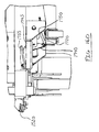
- FIGS. 3-6 illustrate one embodiment of a hitch assembly including a rotating hitch stop.
- the hitch assembly 300 may generally include a rotating hitch stop 305 , an elongated body 310 , catch members 315 , and a control assembly, including a control cable 320 and a mechanical arrangement 325 enclosed within the body 310 and which is discussed in further detail below.
- the hitch assembly 300 may also include a biasing member 330 .
- the elongated body 310 includes a cart end 335 and a mover end 340 .
- the cart end 330 of the elongated body 310 may be releasably coupled to a cart 125 .
- the elongated body 310 is generally rectangular in shape with a partially sloped cart end 345 configured to engage a cart 125 .
- the elongated body 310 may be cylindrical or other suitable shape appropriate to engage a cart 125 and a mover 120 .
- the elongated body 310 may be constructed of stainless steel, aluminum, plastic, or other suitable material with strength appropriate for the weight of the load, or any combination thereof.
- the cart end 335 of the body 310 may include a cart face 350 and catch members 315 .
- the cart face 350 of the cart end 335 of the body 310 may be partially sloped and may generally be configured so as to not hinder a cart 125 from engaging the catch members 315 and the rotating hitch stop 305 . In some embodiments, the cart face 350 may be configured to engage a cart 125 .
- the rotating hitch stop 305 may include flanges 355 , a plate 360 , and a fastening member 365 .
- the rotating hitch stop 305 may rotate in a horizontal plane about the fastening member 365 to engage and stop a cart 125 .
- the rotating hitch stop 305 may be pivotally coupled to the elongated body 310 via the fastening member 365 .
- the stop 305 may also be operably coupled to a biasing member 330 .
- the fastening member 365 may be a screw, a bolt, or other suitable mechanical fastener or combination of fasteners.
- the fastening member may further include a washer.
- the rotating hitch stop 305 may be constructed of stainless steel, aluminum, plastic, or other suitable material with strength appropriate for the weight of the load, or any combination thereof.
- the rotating hitch stop 305 may be rotated about the fastening member 365 and engage a cart 125 from one of three different positions with one of three different flanges 355 a , 355 b , 355 c .
- the flanges 355 may vary in height, width, and length from the fastening member 365 , in order to accommodate various types of carts 125 .
- the flanges 355 may also vary in shape and may include a horizontal portion 370 in addition to a vertical portion 375 to abut or engage a vertical wall of the cart 125 , for example, at a lip or hitch engagement feature of the floor 140 of the cart.
- the flanges 355 may increase efficiency because multiple types of carts 125 may be coupled to a mover 120 utilizing a single rotating hitch stop 305 . While a rotating hitch stop 305 having three different flanges 355 is illustrated, it is recognized that the rotating hitch stop 305 may include a suitable number of two or more flanges 355 as may be deemed desirable.
- the biasing member 330 may be a spring, spring-like device, or the like.
- the biasing member 330 may be operably connected to the elongated body 310 and to the rotating hitch stop 305 .
- the biasing member 330 may provide tension to the stop 305 , such that the stop 305 may engage a cart 125 and hinder the progress of the cart 125 towards the cart mover 120 .
- the biasing member 330 can maintain flange 355 a of the rotating hitch stop 305 in a first position (e.g., FIG. 5A ) for engagement with the cart 125 , while not hindering the selection of other flanges 355 b , 355 c .
- the rotating hitch stop 305 may be rotated into, for example, a second or third position, such that flanges 355 b , 355 c , respectively, may be positioned for engagement with the cart 125 as needed.
- the rotating hitch stop 305 may further include a detent mechanism for selecting and maintaining a flange 355 in its respective position for engagement with the cart 125 .
- the mover end 340 of the elongated body 310 may be operably or pivotally coupled to a cart mover 120 via fastening members 380 and the control assembly.
- the fastening members 380 may be screws, bolts, or other suitable mechanical fasteners, or combinations thereof.
- the hitch assembly 300 may pivot about one of the fastening members 380 in a vertical plane and about another fastening member 380 in a horizontal plane.
- the mover 120 may include a spring assembly 600 operably coupled to the mover end 340 of the elongated body 310 of the hitch assembly 300 .
- the spring assembly 600 may provide a control mechanism for the horizontal rotation of the hitch assembly 300 about fastening member 380 a and generally does not hinder the vertical rotation of the assembly 300 about fastening member 380 b , as described in more detail below.
- the spring assembly 600 can bias the hitch assembly 300 to generally align longitudinally with the mover 120 .
- the hitch assembly 300 may rotate in a horizontal plane about fastening member 380 a to allow the assembly 300 and a cart 125 to turn and generally move during transport of the cart 125 .
- the spring assembly 600 can be biased to return the hitch assembly 300 to a generally longitudinally aligned position following a turn.
- the assembly 300 when not in use and when a cart 125 is not coupled to the mover 120 , the assembly 300 may be placed in a storage position on the mover 120 .
- the hitch assembly 300 may rotate in a vertical plane in a direction illustrated by arrows C, about fastening member 380 b , thereby allowing the assembly 300 to “fold up” or “fold into” the mover 120 in a storage position.
- the hitch assembly 300 may rotate in a vertical plane in a direction illustrated by arrows C, about fastening member 380 b , thereby allowing the assembly 300 to come out of the storage position.
- the spring assembly 600 may bias to some extent during vertical rotation, the spring assembly 600 can be configured such that it does not substantially hinder the vertical rotation of the hitch assembly 300 .
- the catch members 315 may include a first face 405 and a second face 410 .
- the faces 405 , 410 may be connected by a rounded or curved edge 415 .
- none, some, or all of the faces 405 , 410 , and edge 415 may contact the cart 125 .
- each catch member 315 may include a pivot point 605 , a spring 610 , and a catch member tab 615 , which, along with the cable 320 , can form part of the control assembly. The release or disengagement of the catch members 315 can be controlled via the control assembly.
- the catch members 315 may be pivotally coupled to the body 310 via their respective catch member tab 615 , which may receive, in a pivotal configuration, a rod 620 that extends through the pivot points 605 and the body 310 .
- the catch members 315 may each be coupled to their respective spring 610 via the catch member tab 615 , and the opposite end of each spring 610 may be coupled to the body 310 .
- the catch members 315 may pivot in unison. In other embodiments, the catch members 315 may not pivot in unison. In one embodiment, there are two catch members 315 . However, in other embodiments, there may be fewer or greater catch members 315 .
- the catch members 315 may be constructed of stainless steel, aluminum, plastic, or other suitable material with strength appropriate for the weight of the load, or any combinations thereof. Each member 315 may have its own dedicated spring 610 or, alternatively, in some embodiments, a single spring 610 may bias both catch members 315 .
- the control assembly may further include a pivot rod 625 , a linkage 630 , a tab 635 , a rotating plate 640 , a cable connective end 645 , and/or a coupling member 650 .
- a first end of the cable 320 may be operably coupled to a lever of the mover 120 , and the opposite end of the cable 320 may include the connective end 645 that couples the second end of the cable 320 to the rotating plate 640 .
- the sheath of the cable 320 may be coupled via the coupling member 650 to the body 310 , such that the inner cable portion can displace relative to the cable sheath when the lever on the mover 120 is displaced.
- the rotating plate 640 may be pivotally coupled to the elongated body 310 via the pivot rod 625 extending through the tab 635 of the body 310 .
- the rotating plate 640 may be further coupled to the linkage 630 , and the linkage 630 may be coupled to a catch member tab 615 .
- the control assembly can control the coupling and release of the catch members 315 to a cart 125 .
- the catch members 315 may pivot about their pivot points 605 in a vertical plane to engage a cart 125 and hinder the movement of the cart 125 once engaged.
- the framework or other aspect of the cart 125 being engaged may press against the catch members 315 to cause the catch members 315 to pivot or rotate about the pivot points 605 and pivot rod 620 in direction D, and thereby extending the spring 610 until the cart 125 abuts the rotating hitch stop 305 .
- the spring 610 may bias the catch members 315 such that the members 315 pivot or rotate in direction E to engage the floor 140 or the lip or hitch engagement feature of the cart 125 .
- a lever of the cart mover 120 may be used or engaged to displace the cable 320 of the control assembly, pulling the cable 320 in direction F.
- the rotating plate 640 can be caused to pivot in a clockwise direction about the pivot rod 625 on the tab 635 .
- the linkage 630 follows, thereby pulling a catch member 315 or catch members, via the catch member tab 615 , in direction D and thereby disengaging the catch members 315 from the cart 125 .
- the cart 125 may also be disengaged from the rotating hitch stop 305 .
- the cart 125 may be removed from the hitch assembly 300 , the lever of the cart may be released, the above described process will be reversed, and the spring biased catch members 315 can bias into their original positions.
- FIGS. 7-10 illustrate another embodiment of a rotating hitch stop 705 .
- the rotating hitch stop 705 may include flanges 755 , a plate 760 , and a fastening member 765 .
- the rotating hitch stop 705 may rotate in a horizontal plane about the fastening member 765 to engage and stop a cart 125 .
- the rotating hitch stop 705 may be pivotally coupled to the elongated body 310 via the fastening member 765 .
- the fastening member 765 may be spring-loaded or fixed, may be a screw, a bolt, or other suitable mechanical fastener or combinations thereof, and may be a part of a detent mechanism.
- the rotating hitch stop 705 may be constructed of stainless steel, aluminum, plastic, or other suitable material with strength appropriate for the weight of the load, or any combinations thereof.
- the plate 760 may include at least three holes 905 .
- the plate 760 may include greater or fewer than three holes.
- the holes 905 form the corner points for a generally triangular shape about the fastening member 765 .
- the holes 905 may form a different shape about the fastening member 765 , such as a circle or other round or polygonal shape.
- the shape formed by the holes 905 may vary depending on the number of holes 905 provided.
- the rotating hitch stop 705 can rotate about the fastening member 765 .
- a spring-loaded fastening member 765 can press down on the rotating hitch stop 705 while still allowing the hitch stop 705 to be rotated, such that a hole 905 may align with a fixed fastening member 910 (see FIG. 10 ), forming a detent arrangement.
- the fastening member 765 may be fixed and the fastening member 910 may be spring loaded.
- the flanges 755 vary in height, width, and length from the fastening member 765 , in order to accommodate various types of carts 125 .
- the flanges 755 may also vary in shape and may include a horizontal portion 770 in addition to a vertical portion 775 to abut or engage a vertical wall of the cart 125 .
- the rotating hitch stop 705 may be rotated about the fastening member 765 until a hole 905 engages the fastening member 910 . Each hole 905 may correspond to one of the flanges 755 .
- a hole 905 a , 905 b , 905 c may be engaged by the fastening member 910 when its respective flange 755 a , 755 b , 755 c is in position for engagement with a cart 125 , for example, at a lip or hitch engagement feature of the floor 140 of the cart.
- the flanges 755 may increase efficiency because multiple types of carts 125 may be coupled to a single mover 120 utilizing a single rotating hitch stop 705 . While a rotating hitch stop 705 having three different flanges 755 is illustrated, it is recognized that the rotating hitch stop 705 may include a suitable number of two or more flanges 755 as may be deemed desirable.
- the rotating hitch stop 705 may include a detent mechanism, such as the fastening member 910 , for selecting and maintaining a flange 755 in a position for engagement with a cart 125 .
- each hole 905 can be configured to receive the fastening member 910 , such that during the rotation of the hitch stop 705 , a hole 905 may align with the fastening member 910 .
- the fastening member 910 can engage the hole 905 , thereby hindering or stopping the rotation of the hitch stop 705 about the fastening member 765 and thereby presenting a respective flange 755 to engage a cart 125 .
- the fastening member 765 may be spring-loaded or the like and may provide enough tension when biased against the plate 760 , such that the fastening member 765 hinders or stops the rotation of the hitch stop 705 about the fastening member 765 and thereby presents a respective flange 755 to engage a cart 125 .
- holes 905 and fastening member 910 may be eliminated.
- FIGS. 11-13 illustrate another embodiment of a hitch assembly 1100 including a sliding hitch stop 1105 .
- the hitch assembly 1100 may include a sliding hitch stop 1105 , an elongated body 1110 , catch members 1115 , and a control assembly, including a control cable 1120 and a mechanical arrangement 1125 enclosed within the body 1110 .
- the catch members 1115 and the control assembly, including the control cable 1120 and the mechanical arrangement 1125 enclosed within the body 1110 may be generally similar to and generally operate similar to the catch members 315 and the control assembly discussed above with respect to FIGS. 3-10 .
- the elongated body 1110 may be generally similar to and generally operate similar to the elongated body 310 as described above with respect to FIGS. 3-10 , except the elongated body 1110 of the hitch assembly 1100 may include a sliding hitch stop 1105 and may include holes configured to accept sliding fastening members 1165 , as described in more detail below.
- the sliding hitch stop 1105 may include sliding fastening members 1165 , flanges 1155 , and a plate 1160 having slots 1190 .
- the sliding hitch stop 1105 may slide in a generally horizontal plane via the slots 1190 about the sliding fastening members 1165 to engage and stop a cart 125 .
- the sliding hitch stop 1105 may be slidingly coupled to the elongated body 1110 via the fastening members 1165 .
- the plate 1160 may include slots 1190 configured to receive and slidingly engage the fastening members 1165 .
- the fastening members 1165 may be screws, bolts, or other suitable mechanical fasteners, or combinations thereof.
- the sliding hitch stop 1105 may be constructed of stainless steel, aluminum, plastic, or other suitable material with strength appropriate for the weight of the load, or any combinations thereof.
- flange 1155 a may vary in shape and may include a vertical portion 1175 and a horizontal portion 1170 .
- Flange 1155 b may include a vertical portion 1175 .
- flanges 1155 a , 1155 b may include both vertical and horizontal portions or only vertical portions, or may be shaped in any other suitable or desirable configuration for engagement with a cart 125 .
- Flanges 1155 may engage a cart 125 , and as part of the hitch stop assembly 1105 , may hinder the cart's forward progress.
- the sliding hitch stop 1105 may slidingly adjust such that the distance between flange 1155 a , for example, and the cart end 1135 of the elongated body 1110 may vary. Such variability allows the hitch stop 1105 to accommodate carts 125 with varying floor shapes, configurations, and sizes.
- the hitch stop 1105 may increase efficiency because multiple types of carts 125 may be coupled to a single mover 120 utilizing the hitch stop 1105 .
- a hitch assembly may include a swinging or rotating latch end.
- FIGS. 14-17F illustrate another embodiment of a hitch assembly 1400 , including a swinging or rotating latch end 1500 , which may also be referred to herein as a hitch stop.
- the hitch assembly 1400 may include an elongated body 1410 , biasing attachment members 1430 , and a rotating or swinging latch end or hitch stop 1500 .
- the swinging latch end 1500 of the hitch assembly 1400 may also include fastening members 1465 a , a tab 1505 , an elongated body end 1510 , a middle portion 1515 , and a hook end 1520 .
- the fastening members 1465 a may be bolts, pivot bolts, screws, or the like.
- the tab 1505 , the elongated body end 1510 , the middle portion 1515 , and the hook end 1520 may be made of material similar to that of the elongated body 1410 .
- the elongated body end 1510 may be pivotally coupled to the elongated body 1410 via fastening members 1465 a .
- the elongated body 1405 may include slotted openings 1490 (see FIG. 17B ) configured to receive the fastening members 1465 a , such that the rotating latch end 1500 and the elongated body 1400 may be operably or pivotally coupled.
- the middle portion 1515 may be operably coupled to the elongated body end 1510 via at least one of fastening members 1465 a and 1465 b
- the hook end 1520 may be operably coupled to the middle portion 1515 via at least one of fastening members 1465 b and 1465 c .
- the rotating latch end 1500 may be separate, individual pieces or sections coupled via fastening members or other coupling methods, such as but not limited to welding, or may be a single continuous piece or may be a combination of individual and continuous pieces.
- the hitch assembly 1400 coupled to the cart mover 120 may be placed into position such that the hitch assembly 1400 may begin engagement with the frame 150 of a cart 125 .
- the hitch assembly 1400 may engage the frame 150 , thereby generally securing the cart 125 to the cart mover 120 .
- the cart 125 may now be moved via the cart mover 120 .
- the swinging latch end 1500 may be subsequently disengaged from the cart frame 150 , thereby releasing the cart 125 from the cart mover 120 .
- a hitch assembly 1400 that is coupled to the frame 150 of a cart 125 may be able to pull additional carts or additional weight and is not affected by items that may be on the floor 140 of the cart and further is not affected by the size or shape of the floor 140 .
- the hitch assembly 1400 may include a mover attachment plate 1705 , one or more biasing members 1430 , a rotating or swinging latch end 1500 , fastening members 1465 , a cart engagement ramp 1745 , an elongated body 1410 , and a control assembly.
- the mover attachment plate 1705 may pivotally couple the hitch assembly 1400 to a mover 120 via biasing members 1430 and fastening members 1780 a , 1780 b .
- the biasing members 1430 may be, but are not limited to, springs, spring-like devices, or the like, and the fastening members 1780 may be, but are not limited to, pivot bolts or the like.
- the biasing members 1430 may bias the hitch assembly 1400 to generally align longitudinally with the mover 120 .
- the hitch assembly 1400 may rotate in a generally horizontal plane about fastening member 1780 a to allow the assembly 1400 and a cart 125 to turn and generally move during transport of the cart 125 .
- the biasing members 1430 may help in returning the hitch assembly 1400 to a generally longitudinally aligned position following a turn.
- the assembly 1400 When not in use, in one embodiment, and when a cart 125 is not coupled to the mover 120 , the assembly 1400 may be placed in a storage position on the mover 120 . That is, the hitch assembly 1400 may rotate in a vertical plane in the direction of arrows I, about fastening member 1780 b , thereby allowing the assembly 1400 to “fold up” or “fold into” the mover 120 in a storage position. To remove the assembly 1400 from the storage position, the previously described process can be reversed. While the biasing members 1430 may bias to some extent during vertical rotation, the biasing members 1430 can be configured such that they do not substantially hinder the vertical rotation of the hitch stop assembly 1400 .
- the control assembly may be generally at least partially housed in the elongated body 1410 and may include one or more fastening members 1710 , one or more biasing members 1715 , an operating cable 1420 , a rod 1720 , a bell crank or swinging bracket 1725 , a vertical plate 1730 , a latch actuator 1740 , a tubular member 1750 , and/or a triangle plate 1755 .
- the release or disengagement of the rotating latch 1500 may be controlled via the control assembly.
- a first end of the cable 1420 may be operably coupled to a lever of the mover 120 , and the opposite end of the cable 1420 may include a connective end 1760 that couples the second end of the cable 1420 to the bell crank or swinging bracket 1725 .
- the sheath of the cable 1420 may be coupled via a coupling member 1765 to the body 1410 , such that the inner cable portion can displace relative to the cable sheath when the lever of the mover 120 is displaced.
- the swinging bracket 1725 may also be coupled to the elongated body 1410 via a tab 1770 , and a fastening member 1710 .
- the swinging bracket 1725 may also be coupled to a rod 1720 and a biasing member 1715 .
- the biasing member 1715 may also be coupled to a vertical plate 1730 .
- the rod 1720 may also be coupled to a latch actuator 1740 .
- the latch actuator 1740 may be coupled to a tubular member 1750 and a triangle plate 1755 .
- the cart 125 may engage the cart engagement ramp 1745 .
- the swinging or rotating latch 1500 of the hitch assembly 1400 may engage the cart frame 150 , thereby generally securing the cart 125 to the mover 120 via the hitch assembly 1400 .
- the hook end 1520 may help to guide the cart 125 into engagement with the latch 1500 .
- the hook end 1520 , the middle portion 1515 , and/or the elongated body end 1510 may each engage a side of the frame 150 .
- the tab 1505 and the triangle plate 1755 may also engage the frame 1500 and help maintain the cart frame 150 in an engaged position.
- the triangle plate 1755 can act as a catch member, allowing a cart frame 150 to slide over the triangle plate 1755 and become engaged between the elongated body end 1510 and the triangle plate 1755 , similar in manner to the catch members described above.
- the tab 1505 may engage a top portion of the cart frame 150 , so as to maintain the cart 125 in an engaged position generally between the elongated body end 1510 and the triangle plate 1755 .
- the triangle plate 1755 may be disengaged, as discussed in more detail below, using the control assembly.
- a lever of the cart mover 120 may be used to displace the cable 1420 of the control assembly, pulling the cable 1420 in the direction of arrow J.
- the swinging bracket 1760 may be caused to pivot in a clockwise direction about the fastening member 1710 .
- the biasing member 1715 and rod 1720 may follow, thereby rotating the latch actuator 1740 and pulling the triangle plate 1755 in a generally downward direction.
- the cart 125 When the triangle plate 1755 is in a generally downward position, the cart 125 may be free to move away from the latch 1500 and out of the engaged position generally held between the elongated body end 1510 and the triangle plate 1755 . In this manner, the cart 125 may now be disengaged from the rotating latch 1500 , such as by pulling the cart 125 away from the latch 1500 and back over the triangle plate 1755 , which has been pulled in a generally downward direction. Once disengaged from the rotating latch 1500 , the cart 125 may be removed from the hitch assembly 1400 , the lever of the mover 120 may be released, and the above-described process may be reversed and the rotating latch 1500 may bias into its original position (as shown, for example, in FIG. 14A ).
- triangle plate 1755 may bias back to its original position (as shown, for example, in FIG. 17F ) from the generally downward position. While the phrase “triangle plate” is used herein, it is understood that the term “triangle” is not limiting, and the plate 1755 may be shaped in any suitable shape useful as a catch member in the manner described herein.
- the cart coupling assembly may include engagement members configured to releasably couple a first cart to a second cart.
- the engagement members of the cart coupling assembly may be pivotally coupled.
- the engagement members may be coupled in a fixed relationship.
- FIGS. 18-20C illustrate one embodiment of components of a cart coupling assembly 115 , including engagement members that may be pivotally coupled.
- the cart coupling assembly 115 may be utilized to move multiple carts 125 at one time.
- the cart coupling assembly 115 may reduce the risk of damage to goods in the carts by hindering a trailing cart from hitting the cart or carts in front of it.
- the cart coupling assembly 115 may also increase efficiency because multiple carts can be moved at one time by a single operator and because the side to side movement during transport and turns can be more controlled.
- a cart coupling assembly 115 may include a first engagement portion 1805 and a second engagement portion 1810 .
- Each portion 1805 , 1810 may include one or more cart engagement members 1815 .
- the first portion 1805 and the second portion 1810 may be pivotally coupled such that the individual cart engagement members 1815 a , 1815 b , 1815 c , 1815 d are pivotally coupled to one another, wherein the members 1815 a , 1815 b , 1815 c , 1815 d share a generally common pivotal connection 1820 .
- the cart engagement members 1815 may be pivotally connected to one another at and through a plurality of pivotal connections 1820 , as shown for example in FIG. 19 .
- cart engagement members 1815 of the first portion 1805 and of the second portion 1810 may be connected such that a single arm 1825 a , 1825 b extends from each of the first and second portions 1805 , 1810 , respectively, and pivotally couples the first portion 1805 to the second portion 1810 .
- the first portion 1805 and the second portion 1810 of the cart coupling assembly 115 may each include cart engagement members 1815 .
- the engagement members 1815 may be constructed of stainless steel, aluminum, plastic, or other suitable material with strength appropriate for the weight of the load, or any combinations thereof.
- the engagement members 1815 may each engage a steel tube 155 of a wall 135 of a cart 125 .
- a cart engagement member 1815 may include an arm 1830 and an engagement device 2005 , which may include a hook 2010 , a latch 2015 , and a pivot rod 2020 .
- the hook 2010 and latch 2015 may be releasably coupled to the steel tube engaging end of the engagement member 1815 .
- the hook 2010 may engage the steel tube 155 of a wall 135 of a cart 125
- the latch 2015 may generally lock/secure or unlock/unsecure the hook 2010 to the steel tube 155 .
- the hook 2010 may be generally C-shaped and may include a lip 2030 and a rod or protrusion 2035 on its inner circumference.
- the lip 2030 can help maintain the steel tube 155 of the cart 125 within the hook 2010 , when engaged with the cart 125 .
- the protrusion 2035 may engage the steel tube 155 of the cart 125 and can help maintain the steel tube 155 in position in the hook 2010 while permitting some rotational movement of the steel tube 155 within the hook 2010 .
- the latch 2015 may include a grip member 2040 and a spring member 2045 .
- the latch 2015 may be operably coupled to the arm 1830 via the pivot rod 2020 .
- the spring loaded latch 2015 may be deflected into an unlocked position upon introduction and engagement with a tube, such as the steel tube 155 .
- the spring member 2045 may slide along an anti-friction slide member 2050 located between the arm 1830 and the spring member 2045 .
- the latch 2015 can be self-locking.
- the spring member 2045 may bias into its original position, as shown in FIGS. 20A and C, generally securing the engagement arm 1815 to the steel tube 155 .
- the latch 2015 may be unlocked and the engagement device 2005 detached from the steel tube 155 by pulling on the grip member 2040 , thereby biasing the spring member 2045 as the latch 2015 rotates about the pivot rod 2020 .
- the arms 1830 of the engagement members 1815 a , 1815 b of the first portion 1805 may be substantially straight and may have substantially equal length, and the arms 1830 of the engagement members 1815 c , 1815 d of the second portion 1810 may include a bend 2025 and may have substantially equal length.
- the arms 1830 of the engagement members 1815 a , 1815 b of the first portion 1805 may have a different length than the arms 1830 of the engagement members 1815 c , 1815 d of the second portion 1810 .
- each of the engagement members 1815 may be configured and sized the same, or one or more of the engagement members 1815 may be configured and sized differently from the other engagement members, and all configurations and sizes are within the spirit and scope of the present disclosure.
- the engagement members 1815 a , 1815 b of the first portion 1805 may be coupled to a leading cart 125 a
- the engagement members 1815 c , 1815 d of the second portion 1810 may be coupled to a trailing cart 125 b .
- the bends 2025 in the arms 1830 of the engagement members 1815 c , 1815 d can help to maintain the orientation of the trailing cart 125 b , such that it is moving forward or in-line with the leading cart 125 a and the mover 120 rather than moving side-to-side relative to the leading cart 125 a and the mover 120 .
- the engagement members 1815 a , 1815 b of the first portion 1805 may be coupled to a trailing cart 125 b
- the engagement members 1815 c , 1815 d of the second portion 1810 may be coupled to a leading cart 125 a .
- any or all of the engagement members may or may not include a bend 2025 in the respective arm 1830 .
- FIGS. 21A-C illustrate another embodiment of a cart coupling assembly 115 having engagement members 1830 , which may each include an arm 1830 and an engagement device 2105 , which may include a hook 2110 , a latch 2115 , and a pivot rod 2120 .
- the cart engagement device 2105 may further include a handle 2160 .
- the latch 2115 may include a first end 2165 and second end 2170 .
- the first end 2165 of the latch 2115 may include a grip member 2140 .
- the second end 2170 of the latch 2115 may include a handle 2160 .
- the latch 2115 may be operably coupled to the arm 1830 via the pivot rod 2120 .
- the spring loaded latch 2115 may be deflected into an unlocked position upon introduction and engagement with a tube, such as the steel tube 155 .
- a spring member 2145 may slide along an anti-friction slide member 2150 located between the arm 1830 and the spring member 2145 .
- the latch 2115 can be self-locking.
- the spring member 2145 may bias into its original position, as shown in FIG. 21A , generally securing the engagement arm 1815 to the steel tube 155 .
- the latch 2115 may be unlocked and the engagement device 2105 detached from the steel tube 155 by pushing on the handle 2160 , thereby biasing the spring member 2145 as the latch 2115 rotates about the pivot rod 2120 .
- the latch 2115 may be unlocked by pulling on the grip member 2140 , thereby biasing the spring member 2145 as the latch 2115 rotates about the pivot rod 2120 .
- the latch 2115 may lock/secure or unlock/unsecure the engagement member 1815 to a steel tube 155 of a cart 125 .
- the engagement member 1815 may be disengaged from the steel tube 155 by pulling on the grip member 2140 , or alternatively, the handle 2160 may be pressed thereby engaging a “press to release” feature and unlocking the latch 2115 . An operator may then disengage the steel tube 155 of the cart 125 from the engagement member 1815 .
- FIGS. 22-24 illustrate one embodiment of components of a cart coupling assembly 2200 , including an engagement member with arms that may be coupled in a fixed relationship.
- the cart coupling assembly 2200 may include an engagement member 2205 .
- the engagement member 2205 may include arms 2210 , first and second attachment members 2215 , a telescoping member 2220 , an engagement plate 2225 , and a spring member 2230 .
- the engagement member 2205 may be made of any suitable material, such as stainless steel, plastic, etc., or any combinations thereof.
- the attachment members 2215 may be hooks and latches with associated operating components, as described above, and may operate similarly as described above.
- the engagement member 2205 may include an arm assembly formed from the arms 2210 .
- a first end portion of a first arm 2210 a may be joined to a first end portion of a second arm 2210 b
- a second end portion of the first arm 2210 a may be joined to a first end portion of a third arm 2210 c .
- a second end portion of the second arm 2210 b may be joined to a second end portion of the third arm 2210 c .
- the arms 2210 may form a generally right triangle shape.
- the arm assembly may include greater or fewer arms 2210 and/or may form a different shape, such as but not limited to a square, rectangle, or equilateral triangle.
- Each arm 2210 may be joined to the other arms by any suitable connection method, including but not limited to welding or mechanically fastening.
- an attachment member 2215 may be joined to each end portion of arm 2210 b.
- arm 2210 a may include the spring member 2230 housed within in the arm 2210 a .
- the spring member 2230 may be secured, at one end, to arm 2210 a , for example, using a mechanical fastener or the like.
- the spring member 2230 may be secured, at its other end, to a first end portion of the telescoping member 2220 , for example, using a mechanical fastener 2305 or the like.
- the first end portion of the telescoping member 2220 may be telescopically received within the arm 2210 a .
- the telescoping member 2220 may generally be slid relative to arm 2210 a .
- the spring 2230 may join the telescoping member 2220 to arm 2210 a and prevent the telescoping member 2220 from being disconnected from arm 2210 a.
- An engagement plate 2225 may be joined to a second end portion of the telescoping member 2220 .
- the engagement plate 2225 may include a long leg portion 2235 and a short leg portion 2240 that together define a generally L-shaped engagement plate 2225 .
- a first end portion of the long leg 2235 may be joined to the telescoping member 2220 .
- the long leg 2235 may extend generally transversely to a longitudinal axis of the telescoping member 2220 in a direction generally away from arm 2210 a .
- the short leg 2240 may be joined at an end of the short leg to a second end portion of the long leg 2235 .
- the short leg 2240 may extend from the long leg 2235 generally parallel to the longitudinal axis of the telescoping member 2220 in a direction generally towards the attachment member 2215 a.
- the engagement member 2205 in one embodiment, may be operably attached to a first cart 125 a . More particularly, the engagement plate 2225 may be positioned such that the long 2235 and short legs 2340 partially encompass a first tube 155 of the first cart 125 a , as shown, for example, in FIG. 24 .
- the arm assembly may be pulled generally in the direction of arrow L. As the arm assembly is pulled in direction L, the long leg 2235 of the engagement plate 2225 may engage the first tube 155 .
- first arm 2210 a sliding relative to the telescoping member 2220 in the direction L, thereby moving the first attachment member 2215 a away from engagement plate 2225 .
- the arm assembly may continue to be moved in the direction L until the first attachment member 2215 a is proximate a second tube 155 .
- the first attachment member 2215 a may then be engaged with or coupled to the second tube 155 of the first cart 125 a , as described in detail above.
- spring member 2230 may stretch from an initial rest position. Upon joining the first attachment member 2215 a to the second tube 155 , spring member 2230 may pull engagement plate 2225 toward the first attachment member 2215 a , thus engaging the long leg 2235 of the engagement plate 2225 with the first tube 155 . Such engagement can help resist separation of the engagement plate 2225 from the first tube 155 in directions generally parallel to L. Further, positioning the short leg 2240 on an inside portion of the first tube 155 can help resist separation of the engagement plate 2225 from the first tube 155 in directions generally toward the arm assembly.
- the first tube 155 can engage the short leg 2240 .
- Such engagement can help prevent further movement of the first cart 125 a away from the first arm 2210 a , thus maintaining the joining of the engagement member 2205 to the first cart 125 a .
- the engagement member 2205 can be constrained to rotate about the first attachment member 2215 a , whereby the rotation is limited by the engagement plate 2225 on the first tube 155 .
- the first attachment member 2215 a may be disconnected from the second tube 155 , as described in detail above.
- spring member 2230 may return toward its initial rest position, thus moving first attachment member 2215 a in a direction toward the engagement plate 2225 .
- Engagement plate 2225 may then be moved away from first tube 155 and disengaged from the cart 125 a.
- the engagement member 2205 may be joined to a second cart 125 b .
- second cart 125 b may be positioned proximate engagement member 2205 .
- the second attachment member 2215 b may then be coupled to a third tube 155 of second cart 125 b .
- the carts 125 a and b may be moved in unison, and the trailing cart may follow the leading cart, for example, as illustrated in FIGS. 25A-I .
- the engagement member 2205 can limit relative rotation of the first cart 125 a to the second cart 125 b . More particularly, if second cart 125 b should rotate relative to first cart 25 a from a first position as shown in FIG. 25A to a second position as shown, for examples, in FIGS. 25D and 25G , such rotation is about second attachment member 2215 b.
- the attachment members 2215 may be released, as described above, to disengage the attachment members 2215 from their respective tubes 155 , and the spring member 2230 may bias into its initial rest position, thus allowing the engagement plate 225 to be disengaged from the first tube 155 of the first cart 125 a , as described above.
- FIGS. 26-29C illustrate another embodiment of a cart coupling assembly 2200 including an engagement member 2605 having attachment members 2615 that are configured as carabiners.
- the carabiners may be attached to the arms 2210 by any suitable connection method, such as but not limited to, using mechanical fasteners 2610 .
- the embodiments of cart coupling assembly 2200 of FIGS. 26-29 having attachment members 2615 that are configured as carabiners may be used and operated similarly to the embodiments of cart coupling assemblies described above with respect to FIGS. 22-25I . While carabiners are illustrated, it is also recognized that other types of latches, hooks, connectors, or the like may be suitable for use as engagement members for the various embodiments of cart coupling assemblies 2200 of the present disclosure.
- hitch assemblies and cart coupling assemblies may be used together as a cart transporting apparatus.
- the hitch assemblies may be utilized to releasably couple a cart mover to a cart.
- the description refers to the movement of the cart relative to the mover as if the mover were in front of the cart.
- an operator may position the mover in front of the cart and engage the catch members.
- a hitch stop can be used to hinder the forward progress of the cart, such that an appropriate flange will abut the floor of the cart.
- Additional carts may be operably or pivotally coupled to the first cart via cart coupling assemblies.
- Engagement members may be releasably coupled to the steel tube of the carts.
- the hook of an engagement member may start to engage the steel tube of a cart, thereby biasing the latch of the engagement member such that the latch is in an unlocked position. Once the steel tube is in position within the hook, the latch can bias into a locked position and the hook maintains the steel tube and the cart in position for transport.
- the carts may be disengaged from the cart transporting apparatus.
- the first cart may be removed from the mover by releasing the catch members via a cable and lever assembly attached to the mover and coupled to the hitch stop assembly, as described above.
- the additional carts may be disengaged from each other by unlocking the latches of the engagement members of the cart coupling assemblies and disengaging the steel tubes from the engagement members.
Abstract
Description
Claims (7)
Priority Applications (3)
| Application Number | Priority Date | Filing Date | Title |
|---|---|---|---|
| US12/420,969 US8360459B2 (en) | 2008-04-11 | 2009-04-09 | Cart transporting apparatus |
| US13/725,212 US8870211B2 (en) | 2008-04-11 | 2012-12-21 | Cart transporting apparatus |
| US14/503,974 US9994246B2 (en) | 2008-04-11 | 2014-10-01 | Cart transporting apparatus |
Applications Claiming Priority (4)
| Application Number | Priority Date | Filing Date | Title |
|---|---|---|---|
| US4419208P | 2008-04-11 | 2008-04-11 | |
| US12778408P | 2008-05-14 | 2008-05-14 | |
| US9590708P | 2008-09-10 | 2008-09-10 | |
| US12/420,969 US8360459B2 (en) | 2008-04-11 | 2009-04-09 | Cart transporting apparatus |
Related Child Applications (2)
| Application Number | Title | Priority Date | Filing Date |
|---|---|---|---|
| US13/725,212 Continuation US8870211B2 (en) | 2008-04-11 | 2012-12-21 | Cart transporting apparatus |
| US13/725,212 Division US8870211B2 (en) | 2008-04-11 | 2012-12-21 | Cart transporting apparatus |
Publications (2)
| Publication Number | Publication Date |
|---|---|
| US20090267322A1 US20090267322A1 (en) | 2009-10-29 |
| US8360459B2 true US8360459B2 (en) | 2013-01-29 |
Family
ID=40910043
Family Applications (3)
| Application Number | Title | Priority Date | Filing Date |
|---|---|---|---|
| US12/420,969 Expired - Fee Related US8360459B2 (en) | 2008-04-11 | 2009-04-09 | Cart transporting apparatus |
| US13/725,212 Expired - Fee Related US8870211B2 (en) | 2008-04-11 | 2012-12-21 | Cart transporting apparatus |
| US14/503,974 Expired - Fee Related US9994246B2 (en) | 2008-04-11 | 2014-10-01 | Cart transporting apparatus |
Family Applications After (2)
| Application Number | Title | Priority Date | Filing Date |
|---|---|---|---|
| US13/725,212 Expired - Fee Related US8870211B2 (en) | 2008-04-11 | 2012-12-21 | Cart transporting apparatus |
| US14/503,974 Expired - Fee Related US9994246B2 (en) | 2008-04-11 | 2014-10-01 | Cart transporting apparatus |
Country Status (3)
| Country | Link |
|---|---|
| US (3) | US8360459B2 (en) |
| EP (1) | EP2108563B1 (en) |
| CA (1) | CA2674932A1 (en) |
Cited By (13)
| Publication number | Priority date | Publication date | Assignee | Title |
|---|---|---|---|---|
| US8870211B2 (en) | 2008-04-11 | 2014-10-28 | Dane Technologies, Inc. | Cart transporting apparatus |
| US8894086B2 (en) | 2011-05-10 | 2014-11-25 | Gatekeeper Systems, Inc. | Cart connection assemblies and methods |
| US20150344086A1 (en) * | 2014-05-28 | 2015-12-03 | Ian SCARTH | Industrial cart comprising a mother or primary cart and a secondary or daughter cart |
| US9227645B2 (en) * | 2012-05-25 | 2016-01-05 | Juan Franco | Modular customizable cart |
| US9308790B1 (en) * | 2014-11-06 | 2016-04-12 | Don Sharp | Towing assembly |
| US20160207554A1 (en) * | 2015-01-21 | 2016-07-21 | Dane Technologies, Inc. | Cart Pusher, Mateable Carts, and Related Systems, Methods, and Devices |
| US9403548B2 (en) | 2014-07-25 | 2016-08-02 | Gatekeeper Systems, Inc. | Monitoring usage or status of cart retrievers |
| US20170015161A1 (en) * | 2015-07-16 | 2017-01-19 | David Earle GRANT | Attachment apparatus for securing implements to a vehicle |
| US10625937B2 (en) * | 2018-07-12 | 2020-04-21 | Sharp Kabushiki Kaisha | Conveying device |
| US10668617B2 (en) * | 2015-04-13 | 2020-06-02 | Mobile Industrial Robots A/S | Robotic cart pulling vehicle for automated pulling of carts |
| US10919666B2 (en) * | 2019-01-15 | 2021-02-16 | Target Brands, Inc. | Sled configured for shipping vessel |
| US11167606B2 (en) * | 2019-05-28 | 2021-11-09 | United States Postal Service | Tow device for automated guided vehicle |
| US11655100B2 (en) | 2020-04-06 | 2023-05-23 | Sailrail Automated Systems, Inc. | Cart loader/unloader and a switcher system |
Families Citing this family (24)
| Publication number | Priority date | Publication date | Assignee | Title |
|---|---|---|---|---|
| US7857342B2 (en) | 2005-06-07 | 2010-12-28 | Dane Technologies, Inc. | Hitch assembly |
| US8684373B2 (en) | 2008-09-23 | 2014-04-01 | Dane Technologies, Inc. | Cart moving machine |
| US9010771B2 (en) | 2009-11-10 | 2015-04-21 | Dane Technologies, Inc. | Utility machine with dual-mode steering |
| PL2468104T3 (en) * | 2010-12-23 | 2019-02-28 | Gea Food Solutions Bakel B.V. | Cleaning method for a mould drum |
| US9008829B2 (en) | 2013-01-28 | 2015-04-14 | Amazon Technologies, Inc. | Inventory system with connectable inventory holders |
| US9008828B2 (en) * | 2013-01-28 | 2015-04-14 | Amazon Technologies, Inc. | Inventory system with connectable inventory holders |
| JP5998091B2 (en) * | 2013-03-26 | 2016-09-28 | Kyb株式会社 | Dolly drive assist unit |
| US10071891B2 (en) | 2015-03-06 | 2018-09-11 | Walmart Apollo, Llc | Systems, devices, and methods for providing passenger transport |
| US20180099846A1 (en) | 2015-03-06 | 2018-04-12 | Wal-Mart Stores, Inc. | Method and apparatus for transporting a plurality of stacked motorized transport units |
| WO2016142794A1 (en) | 2015-03-06 | 2016-09-15 | Wal-Mart Stores, Inc | Item monitoring system and method |
| US9738299B2 (en) * | 2015-09-26 | 2017-08-22 | Toyota Motor Engineering & Manufacturing North America, Inc. | Mother daughter cart system |
| JP6628582B2 (en) * | 2015-12-02 | 2020-01-08 | シャープ株式会社 | Unmanned towing vehicle and unmanned towing system |
| CA2961938A1 (en) | 2016-04-01 | 2017-10-01 | Wal-Mart Stores, Inc. | Systems and methods for moving pallets via unmanned motorized unit-guided forklifts |
| US10093334B1 (en) * | 2017-07-24 | 2018-10-09 | Edmund W. Brown | Mother/daughter industrial cart coupling arrangement |
| US10703151B2 (en) * | 2017-12-21 | 2020-07-07 | Target Brands, Inc. | Tugger cage cart locking device |
| CN108860337B (en) * | 2018-06-03 | 2020-10-20 | 惠安县崇武镇石板然茶叶店 | Shopping cart recycling robot |
| US10913479B1 (en) * | 2018-06-05 | 2021-02-09 | Eddy Cardentey | Motorized stroller accessory |
| CA3126350A1 (en) * | 2019-01-09 | 2020-07-16 | Dane Technologies, Inc. | Manual pallet jack hitch and related systems and methods |
| US10809734B2 (en) | 2019-03-13 | 2020-10-20 | Mobile Industrial Robots A/S | Route planning in an autonomous device |
| US11592299B2 (en) | 2020-03-19 | 2023-02-28 | Mobile Industrial Robots A/S | Using static scores to control vehicle operations |
| NO346887B1 (en) * | 2020-08-18 | 2023-02-13 | Robotnorge As | Apparatus and system for adapting at least one roll container from a nestable configuration to a fillable configuration, and a jig for guiding at least one part of a roll container |
| US11904919B2 (en) | 2021-04-06 | 2024-02-20 | Edmund W. Brown | Apparatus and method for assisting in decoupling a wheels-on-ground daughter cart from a mother cart |
| CN113428205B (en) * | 2021-07-20 | 2023-09-01 | 新疆宏域炜业建设有限公司 | Sewer grating plate carrying device and method for municipal engineering |
| US20230331451A1 (en) * | 2022-04-15 | 2023-10-19 | Sonoco Development, Inc. | Moving system for cores and tubes |
Citations (153)
| Publication number | Priority date | Publication date | Assignee | Title |
|---|---|---|---|---|
| US752300A (en) | 1904-02-16 | Coupling for threshing-machines | ||
| US1050919A (en) | 1911-03-22 | 1913-01-21 | John M Conley | Vise. |
| US2268181A (en) * | 1940-08-17 | 1941-12-30 | Jay O Bolton | Tow bar |
| US2313235A (en) * | 1940-05-06 | 1943-03-09 | Grove Collins Denny | Coupling means for dollys, trailers, and the like |
| US2381190A (en) | 1943-09-13 | 1945-08-07 | Walter J Tiner | Trailer connection |
| US2386195A (en) * | 1944-02-12 | 1945-10-09 | Kenneth C Clark | Vehicle coupler |
| US2497234A (en) | 1947-03-24 | 1950-02-14 | Mylie Salvatore | Tow bar |
| US2518816A (en) | 1946-01-02 | 1950-08-15 | Frank L Powers | Tow bar |
| US2621687A (en) | 1947-12-13 | 1952-12-16 | Rose Gringer | Foldable door supporting clamp |
| US2666654A (en) | 1953-03-12 | 1954-01-19 | Phoenix Engineering & Mfg Comp | Universal bumper hitch |
| US2695179A (en) | 1950-01-04 | 1954-11-23 | Steve Fancsali | Adjustable frame structure for corn detasselers |
| US2733078A (en) * | 1956-01-31 | brehm | ||
| US2790513A (en) | 1956-07-10 | 1957-04-30 | Elwell Parker Electric Co | Control circuit for industrial lift trucks |
| US2790992A (en) | 1954-08-11 | 1957-05-07 | Walter E Schirmer | Hinge construction |
| US2827307A (en) | 1956-04-10 | 1958-03-18 | Clarence E Osborn | Selective implement hitch |
| US2846018A (en) | 1955-09-02 | 1958-08-05 | Ronald G Puckett | Vehicle tow truck |
| US2859050A (en) * | 1956-01-12 | 1958-11-04 | Creed I Stonerock | Tractor towing hitch |
| US2877911A (en) | 1954-11-05 | 1959-03-17 | John Reginald Sharp And Emmanu | Trucks for handling aircraft |
| US2904202A (en) | 1954-03-10 | 1959-09-15 | Clark Equipment Co | Clamp mechanism |
| US2935161A (en) | 1957-11-07 | 1960-05-03 | Allis Chalmers Mfg Co | Safety system for load elevating vehicles |
| US3127209A (en) | 1964-03-31 | Clamping mechanism | ||
| US3454285A (en) * | 1967-08-11 | 1969-07-08 | Winpower Mfg Co | Offset actuated hitch |
| US3524512A (en) | 1968-02-21 | 1970-08-18 | Elton L Voeks | Self-propelled driving and steering truck for shopping carts |
| US3549174A (en) * | 1968-09-27 | 1970-12-22 | Ray P Miles | Tow bar assembly |
| US3575250A (en) | 1968-12-23 | 1971-04-20 | Battery Power Unit Co Inc | Self-propelled electric vehicle and battery mount |
| US3633086A (en) | 1969-02-12 | 1972-01-04 | Siemens Ag | Closed-loop regulating system for a control circuit with a control drive |
| US3791474A (en) | 1971-04-02 | 1974-02-12 | Crown Controls Corp | Motion selector device for a lift truck |
| US3794355A (en) * | 1971-10-01 | 1974-02-26 | W Cracolice | Expansion trailer hitch |
| US3829131A (en) * | 1973-03-07 | 1974-08-13 | Moore J | Aircraft tow bar |
| US3876024A (en) * | 1972-12-07 | 1975-04-08 | Said Charles S Mitchell To Sai | Motorized vehicle for moving hospital beds and the like |
| US3887095A (en) | 1974-03-18 | 1975-06-03 | Todo Seisakusho Ltd | Power-operated vehicle |
| US3922006A (en) | 1974-10-15 | 1975-11-25 | Alfred Richard Borges | Selectable and height adjustable hitch |
| US3951434A (en) | 1975-01-31 | 1976-04-20 | Sause Alfred J | Three-way trailer hitch |
| US4029333A (en) | 1974-12-09 | 1977-06-14 | Roll-Rite Corporation | Double ended warehouse trailer |
| FR2246415B3 (en) | 1973-10-06 | 1977-07-15 | Wiedemann Konrad | |
| US4047734A (en) * | 1976-02-23 | 1977-09-13 | Copperloy Corporation | Tow bar assembly |
| US4053025A (en) | 1976-07-14 | 1977-10-11 | Slusarenko John A | Scaffold including reversible and adjustable driving and steering unit |
| AT340315B (en) | 1975-08-06 | 1977-12-12 | Dickertmann Hebezeugfabrik A G | DEVICE FOR VERTICAL AND HORIZONTAL MOVEMENT OF LOADS |
| US4096920A (en) | 1976-12-30 | 1978-06-27 | Bennington Heyn | Powered shopping cart and trailer |
| US4127202A (en) * | 1977-10-31 | 1978-11-28 | Jennings Frederick R | True tracking trailer |
| US4265337A (en) | 1979-07-16 | 1981-05-05 | Crown Controls Corporation | Fork lift truck speed control dependent upon fork elevation |
| US4266903A (en) | 1979-08-27 | 1981-05-12 | Offset Newspaper Equipment Inc. | Lifting dollie |
| GB1601930A (en) | 1977-12-14 | 1981-11-04 | Icms Ltd | Devices for driving mobile trolleys |
| US4429894A (en) * | 1979-01-03 | 1984-02-07 | Alain Feuvray | Fastening device for a trailer and trailer comprising such a device |
| US4531757A (en) | 1984-03-12 | 1985-07-30 | Deere & Company | Tractor hitch arrangement |
| US4544324A (en) * | 1983-04-29 | 1985-10-01 | Kenhar Products Incorporated | Quickchange fork |
| US4573549A (en) | 1983-09-07 | 1986-03-04 | Pankow Arnold A | Portable golf car |
| US4611948A (en) | 1979-08-09 | 1986-09-16 | Johnson Lawrence N | Boat trailer with pivotal dropped crossbar rolled mounting system |
| US4634337A (en) | 1985-01-10 | 1987-01-06 | Dover Corporation | Integrated wheel lift wrecker |
| JPS62149504A (en) * | 1985-12-24 | 1987-07-03 | Yokohama Yuso Kk | Truck for cargo handling |
| US4730685A (en) | 1983-09-13 | 1988-03-15 | Tana Jyra Ky | Apparatus for moving a multi-wheeled vehicle |
| US4771840A (en) | 1987-04-15 | 1988-09-20 | Orthokinetics, Inc. | Articulated power-driven shopping cart |
| US4793763A (en) | 1985-07-08 | 1988-12-27 | Vulcan Equipment Company Limited | Towing apparatus with front stop |
| US4799705A (en) | 1985-12-02 | 1989-01-24 | Janes John B | Trailer hitching aid |
| EP0326754A2 (en) | 1987-12-09 | 1989-08-09 | Universal Automation Technology Limited | Dolly for vehicles |
| US4878050A (en) | 1987-03-06 | 1989-10-31 | Kelley William L | Motor vehicle remote control system |
| FR2587291B1 (en) | 1985-09-13 | 1990-05-11 | Audouin Jean | MOTORIZED TROLLEY FOR USE IN PARTICULAR IN SUPERMARKETS AND HYPERMARKETS |
| US4942529A (en) | 1988-05-26 | 1990-07-17 | The Raymond Corporation | Lift truck control systems |
| US4964837A (en) | 1989-02-16 | 1990-10-23 | Collier Harry B | Radio controlled model vehicle having coordinated sound effects system |
| US5011169A (en) | 1989-06-05 | 1991-04-30 | Harold Henderson | Human power shopping cart propulsion device |
| US5048626A (en) | 1989-06-01 | 1991-09-17 | Carl Hurth Maschinen- Und Zahnradfabrik Gmbh & Co. | Drive system for an industrial vehicle, in particular for a pedestrian controlled forklift |
| US5064012A (en) | 1989-10-17 | 1991-11-12 | Martine Losego | System for motorizing a shopping cart or trolly, or the like |
| US5082074A (en) | 1988-07-09 | 1992-01-21 | Lafis Lagertechnik Fischer Gmbh & Co Kg | Transport vehicle |
| US5096358A (en) | 1990-09-19 | 1992-03-17 | Fmc Corporation | Method and apparatus for removing a disabled automatic guided vehicle from an elevator |
| US5143393A (en) | 1991-03-19 | 1992-09-01 | Una-Goose Company, Inc. | Gooseneck trailer mounting ball installation for pick-up truck |
| US5161634A (en) | 1990-03-27 | 1992-11-10 | Kubota Corporation | Electric vehicle |
| US5167389A (en) | 1990-10-22 | 1992-12-01 | Reimers Eric W | Self propelled golf bag cart |
| EP0405230B1 (en) | 1989-06-28 | 1993-04-28 | Kahlbacher, Anton | Lifting device for lifting vehicles |
| US5322306A (en) | 1989-04-10 | 1994-06-21 | Rosecall Pty Ltd. | Vehicle for conveying trolleys |
| US5322313A (en) | 1993-04-29 | 1994-06-21 | Schroeder Robert D | Multiple connector trailer hitch |
| US5335856A (en) * | 1992-10-13 | 1994-08-09 | Fmc Corporation | Air boom sprayer trailer hitch and suspension |
| US5340202A (en) | 1991-10-30 | 1994-08-23 | Raymond Corporation | Service braking technique for material handling vehicles |
| US5388176A (en) | 1992-04-06 | 1995-02-07 | Briggs & Stratton Corp. | DC motor speed control system |
| US5439069A (en) | 1992-11-27 | 1995-08-08 | Beeler; Jimmy A. | Nested cart pusher |
| US5483615A (en) | 1994-06-17 | 1996-01-09 | Hallidy; William M. | Direct current electrical motor system and method of using same |
| US5511926A (en) | 1990-09-11 | 1996-04-30 | Iles; Frank | Movement of aircraft |
| US5518260A (en) | 1994-12-12 | 1996-05-21 | Chrysler Corporation | Disabled vehicle mover |
| US5529427A (en) * | 1995-01-09 | 1996-06-25 | Bost; Charles H. | Wheelchair coupler apparatus |
| US5560630A (en) | 1995-06-01 | 1996-10-01 | J.B.J. Mfg. Inc. | Rotating multiple ball trailer hitch |
| US5573078A (en) | 1994-08-18 | 1996-11-12 | Stringer; Calvin R. | Steerable, self-powered shopping cart towing apparatus and method for making same |
| US5580207A (en) | 1993-12-21 | 1996-12-03 | Elaut, Naamloze Vennootschap | Device for moving beds |
| US5592355A (en) | 1994-10-06 | 1997-01-07 | Matsushita Electric Industrial Co., Ltd. | Motor control circuit |
| US5633544A (en) | 1993-09-28 | 1997-05-27 | Honda Giken Kogyo Kabushiki Kaisha | Wheel motor |
| US5711542A (en) * | 1996-02-12 | 1998-01-27 | The United States Of America As Represented By The Secretary Of The Army | Trailer hitch adapter |
| US5743347A (en) | 1993-05-15 | 1998-04-28 | Gingerich; Newton Roy | Electric powered small tractor |
| JPH10127401A (en) * | 1996-10-29 | 1998-05-19 | Takashi Nagata | Movable, and temporary connected chair |
| US5762155A (en) | 1994-11-29 | 1998-06-09 | Richard Van Seenus Nederland B.V. | Wheelchair frame and castor assembly |
| US5769051A (en) | 1996-05-29 | 1998-06-23 | Bayron; Harry | Data input interface for power and speed controller |
| US5775714A (en) * | 1996-03-15 | 1998-07-07 | Meadows; Leon | Tow bar |
| US5783989A (en) | 1992-05-22 | 1998-07-21 | Issa; Darrell E. | Alarm sensor multiplexing |
| US5786542A (en) * | 1996-11-04 | 1998-07-28 | The United States Of America As Represented By The Secretary Of The Army | Anti-personnel mine clearing system |
| US5791669A (en) | 1997-01-24 | 1998-08-11 | Broddon; James L. | Shopping cart caddy |
| US5808376A (en) | 1994-11-28 | 1998-09-15 | Analogic Corporation | Method of and apparatus for power management and distribution in a medical imaging system |
| US5860485A (en) | 1996-05-28 | 1999-01-19 | Rhino Craft, Inc. | Grocery cart mover |
| US5880652A (en) | 1996-06-07 | 1999-03-09 | U.S. Philips Corporation | Stripline filter with stripline resonators of varying distance therebetween |
| US5890727A (en) | 1997-05-08 | 1999-04-06 | May; Gregory B. | Trailer hitch assembly |
| US5934694A (en) | 1996-02-13 | 1999-08-10 | Dane Industries | Cart retriever vehicle |
| US5947490A (en) | 1995-05-26 | 1999-09-07 | Applied Sweepers Limited | Pedestrian operated machine with foldaway seat |
| US5964313A (en) | 1996-07-30 | 1999-10-12 | Raymond Corporation | Motion control system for materials handling vehicle |
| US5984333A (en) | 1996-06-21 | 1999-11-16 | Ligtvoet Products B.V. | Wheelchair which is provided with a swivel castor |
| US5983614A (en) | 1997-12-12 | 1999-11-16 | Snapper, Inc. | Lockable front wheel swivel for lawn mowers |
| US6022031A (en) | 1994-05-27 | 2000-02-08 | Four D, Incorporated | Child carrier accessory attachable to a shopping or luggage cart |
| GB2342327A (en) | 1998-09-17 | 2000-04-12 | Nigel Alexander Buchanan | Powered vehicle mover |
| US6060859A (en) | 1997-09-30 | 2000-05-09 | Kabushiki Kaisha Toshiba | Motor driver having a booster circuit and an inverter both controlled by pulse width modulation |
| US6070679A (en) | 1996-07-11 | 2000-06-06 | Lindbergh Manufacturing, Inc. | Powered utility cart having engagement adapters |
| BE1012207A6 (en) | 1998-07-07 | 2000-07-04 | Pis Nv | Device for repositioning a wheeled bed |
| US6109379A (en) | 1997-07-25 | 2000-08-29 | Madwed; Albert | Independently pivotable drivewheel for a wheeled chassis |
| US6116633A (en) | 1998-12-24 | 2000-09-12 | Pride; William J. | Combination ball and pin trailer hitch |
| US6144125A (en) | 1998-05-11 | 2000-11-07 | Orville J. Birkestrand | Contactless electronic control system for modular motorized wheel hub |
| GB2332405B (en) | 1997-05-15 | 2000-12-20 | Andrew Ernie Glozier | Improvements in shopping trolleys |
| US6168367B1 (en) | 1997-07-31 | 2001-01-02 | Coy J. Robinson | Shopping cart collection vehicle and method |
| US6220379B1 (en) | 1996-02-13 | 2001-04-24 | Dane Industries, Inc. | Cart retriever vehicle |
| US6244366B1 (en) | 1997-08-07 | 2001-06-12 | Smarte Carte, Inc. | Cart transporter |
| US6260643B1 (en) | 1999-05-18 | 2001-07-17 | Rhino Craft, Inc. | Cart puller with retaining cord mechanism |
| US6352130B2 (en) | 1997-05-29 | 2002-03-05 | John J. Klein | Towing apparatus |
| US6378642B1 (en) | 2001-02-26 | 2002-04-30 | Eugene R Sutton | Motorized scooter |
| US20020053782A1 (en) | 2000-11-08 | 2002-05-09 | Peters Weldon J. | Trailer impact suppression apparatus |
| US6394481B1 (en) * | 2000-12-27 | 2002-05-28 | Advanced Micro Devices, Inc. | Draw bar clamp lock |
| US6406250B2 (en) | 2000-02-14 | 2002-06-18 | Steven Charles Jaeger | Method of conveying trollies |
| NL1016924C2 (en) | 2000-12-20 | 2002-06-21 | D D Elan V O F | Motorised cart for moving objects on wheels, has steering device cooperating with two sets of wheels with variable steering ratio |
| US6435803B1 (en) | 1998-07-02 | 2002-08-20 | Coy J. Robinson | Shopping cart collection vehicle and method |
| US6443345B1 (en) * | 1998-07-15 | 2002-09-03 | Graber Products, Inc. | Pivoting extensible rear hitch attachment for equipment carrier |
| US6481514B2 (en) | 2000-03-15 | 2002-11-19 | Fuji Jukogyo Kabushiki Kaisha | Auxiliary power device of wheelchair |
| USD475645S1 (en) | 2002-08-12 | 2003-06-10 | Gary Hoonsbeen | Hand-held remote |
| US20030231945A1 (en) | 2002-06-12 | 2003-12-18 | Weatherly Mason C. | Shopping cart mover |
| US6681877B2 (en) | 2000-09-18 | 2004-01-27 | Fuji Jukogyo Kabushiki Kaisha | Working vehicle |
| US6685211B2 (en) | 2001-05-21 | 2004-02-03 | Arthur R. Iles | Trailer dolly |
| US6729636B1 (en) | 2002-08-16 | 2004-05-04 | Phil Lynch | Utility vehicle hitch device |
| US6729421B1 (en) | 2000-06-06 | 2004-05-04 | Kaback Enterprises Inc. | Motor-assist gurney unit and method |
| US6745926B2 (en) * | 2000-08-10 | 2004-06-08 | Thule Sweden Ab | Securement arrangement for a hitch-mount carrier |
| US20040134692A1 (en) | 2002-11-06 | 2004-07-15 | Kime Mark Chandler | Freestanding self-propelled device for moving objects |
| US6820887B1 (en) | 2003-03-14 | 2004-11-23 | Robert E. Riggle | Dolly for towing trailers |
| US20040245030A1 (en) | 2003-06-09 | 2004-12-09 | Dane Industries, Inc. | Cart pulling vehicle with dual cable drums and dual torsion springs |
| US20040256166A1 (en) | 2003-05-03 | 2004-12-23 | Holtan Paul D. | Cart mover |
| US20050006874A1 (en) | 2003-07-08 | 2005-01-13 | Mrofka Robert J. | Towing hitch extension |
| US6871714B2 (en) | 2001-10-26 | 2005-03-29 | Daniel Johnson | Hospital bed power-assist |
| US20050098364A1 (en) | 2003-09-23 | 2005-05-12 | Johnson Daniel T. | Power-assisted cart retriever with attenuated power output |
| US20050116431A1 (en) | 2003-10-15 | 2005-06-02 | Holtan Paul D. | Cart coupler assembly for cart collection machines |
| US20050269114A1 (en) | 2004-06-07 | 2005-12-08 | Marc Turgeon | Self-aligning and self-locking hitch assembly |
| US20060000664A1 (en) | 2004-07-02 | 2006-01-05 | Chao-Kuo Huang | Motorized apparatus for towing a wheelchair |
| US6997471B1 (en) | 2004-06-03 | 2006-02-14 | Daniel John D | Multi-hitch apparatus and method |
| US7029019B1 (en) | 2003-06-09 | 2006-04-18 | Steven Dye | Attachment for a host vehicle for moving a selected item |
| US20060103094A1 (en) * | 2004-11-01 | 2006-05-18 | Wiff James W | Pallet cart |
| US20060102392A1 (en) | 2001-10-26 | 2006-05-18 | Johnson Daniel T | Bed transfer system |
| US20060197295A1 (en) | 2003-10-15 | 2006-09-07 | Dane Industries, Inc. | Push-pull cart collection device and conversion assembly |
| US20060243500A1 (en) | 2005-02-25 | 2006-11-02 | Wiff James W | Wheelchair transporter |
| US20060244226A1 (en) | 2005-04-28 | 2006-11-02 | Ondrasik V J | Shopping cart tether system and method |
| US7134515B2 (en) | 2002-01-07 | 2006-11-14 | Lenkman Thomas E | Utility transport system |
| US20060273547A1 (en) | 2005-06-07 | 2006-12-07 | Holtan Paul D | Hitch Assembly |
| US20070013157A1 (en) * | 2005-07-18 | 2007-01-18 | Wiff James W | Dual hitch assembly |
| US20070289787A1 (en) | 2005-02-25 | 2007-12-20 | Dane Industries, Inc. | Wheelchair transporter |
| EP1454787B1 (en) | 2003-03-07 | 2008-10-15 | Yamaha Hatsudoki Kabushiki Kaisha | Electric vehicle |
| US7905507B2 (en) * | 2004-05-21 | 2011-03-15 | Ottavio Perri | Trailer reversal self-correcting assembly |
Family Cites Families (14)
| Publication number | Priority date | Publication date | Assignee | Title |
|---|---|---|---|---|
| US1677618A (en) * | 1925-08-24 | 1928-07-17 | Highway Trailer Co | Industrial trailer |
| US3223434A (en) * | 1963-06-28 | 1965-12-14 | Yale & Towne Inc | Pallet truck coupling |
| DE1482482A1 (en) * | 1965-06-29 | 1969-01-16 | Rau Ohg Maschf | Adjustment device on a three-point linkage for attaching an agricultural device to a tractor |
| GB1159135A (en) * | 1965-11-26 | 1969-07-23 | Kloeckner Humboldt Deutz Ag | A Link Bar for an Appliance-attachment Device for Motor Vehicles |
| US3572759A (en) * | 1968-12-23 | 1971-03-30 | Allis Chalmers Mfg Co | Latch control means |
| US4305601A (en) * | 1980-03-17 | 1981-12-15 | Kermit Berge | Shopping cart for the handicapped |
| CA2080446C (en) * | 1992-07-21 | 1996-05-07 | Francis V. Smith | Tow-hitch and gooseneck attachment for hauling vehicles |
| EP0646580B1 (en) * | 1993-09-16 | 2000-05-31 | Ciba SC Holding AG | Vinylether compounds with additional functional groups differing from vinylether and their use in the formulation of curable compositions |
| US5489112A (en) * | 1994-09-27 | 1996-02-06 | Warrington; Bruce | Hitch mount |
| US6485046B1 (en) * | 2001-10-15 | 2002-11-26 | Paul Hsueh | Anti-sway trailer hitch |
| US7004489B2 (en) * | 2003-04-02 | 2006-02-28 | Topper Industrial, Inc. | Connection device for interconnecting tugger carts |
| US7364181B2 (en) * | 2005-10-11 | 2008-04-29 | Macdon Industries Ltd. | Self locking coupling device |
| US7712558B2 (en) * | 2007-09-06 | 2010-05-11 | Mh Logistics Corp. | Rolltainer transporter |
| CA2674932A1 (en) | 2008-04-11 | 2009-10-11 | Dane Technologies, Inc. | Cart transporting apparatus |
-
2009
- 2009-04-09 CA CA002674932A patent/CA2674932A1/en not_active Abandoned
- 2009-04-09 US US12/420,969 patent/US8360459B2/en not_active Expired - Fee Related
- 2009-04-14 EP EP09251094.0A patent/EP2108563B1/en not_active Not-in-force
-
2012
- 2012-12-21 US US13/725,212 patent/US8870211B2/en not_active Expired - Fee Related
-
2014
- 2014-10-01 US US14/503,974 patent/US9994246B2/en not_active Expired - Fee Related
Patent Citations (163)
| Publication number | Priority date | Publication date | Assignee | Title |
|---|---|---|---|---|
| US2733078A (en) * | 1956-01-31 | brehm | ||
| US752300A (en) | 1904-02-16 | Coupling for threshing-machines | ||
| US3127209A (en) | 1964-03-31 | Clamping mechanism | ||
| US1050919A (en) | 1911-03-22 | 1913-01-21 | John M Conley | Vise. |
| US2313235A (en) * | 1940-05-06 | 1943-03-09 | Grove Collins Denny | Coupling means for dollys, trailers, and the like |
| US2268181A (en) * | 1940-08-17 | 1941-12-30 | Jay O Bolton | Tow bar |
| US2381190A (en) | 1943-09-13 | 1945-08-07 | Walter J Tiner | Trailer connection |
| US2386195A (en) * | 1944-02-12 | 1945-10-09 | Kenneth C Clark | Vehicle coupler |
| US2518816A (en) | 1946-01-02 | 1950-08-15 | Frank L Powers | Tow bar |
| US2497234A (en) | 1947-03-24 | 1950-02-14 | Mylie Salvatore | Tow bar |
| US2621687A (en) | 1947-12-13 | 1952-12-16 | Rose Gringer | Foldable door supporting clamp |
| US2695179A (en) | 1950-01-04 | 1954-11-23 | Steve Fancsali | Adjustable frame structure for corn detasselers |
| US2666654A (en) | 1953-03-12 | 1954-01-19 | Phoenix Engineering & Mfg Comp | Universal bumper hitch |
| US2904202A (en) | 1954-03-10 | 1959-09-15 | Clark Equipment Co | Clamp mechanism |
| US2790992A (en) | 1954-08-11 | 1957-05-07 | Walter E Schirmer | Hinge construction |
| US2877911A (en) | 1954-11-05 | 1959-03-17 | John Reginald Sharp And Emmanu | Trucks for handling aircraft |
| US2846018A (en) | 1955-09-02 | 1958-08-05 | Ronald G Puckett | Vehicle tow truck |
| US2859050A (en) * | 1956-01-12 | 1958-11-04 | Creed I Stonerock | Tractor towing hitch |
| US2827307A (en) | 1956-04-10 | 1958-03-18 | Clarence E Osborn | Selective implement hitch |
| US2790513A (en) | 1956-07-10 | 1957-04-30 | Elwell Parker Electric Co | Control circuit for industrial lift trucks |
| US2935161A (en) | 1957-11-07 | 1960-05-03 | Allis Chalmers Mfg Co | Safety system for load elevating vehicles |
| US3454285A (en) * | 1967-08-11 | 1969-07-08 | Winpower Mfg Co | Offset actuated hitch |
| US3524512A (en) | 1968-02-21 | 1970-08-18 | Elton L Voeks | Self-propelled driving and steering truck for shopping carts |
| US3549174A (en) * | 1968-09-27 | 1970-12-22 | Ray P Miles | Tow bar assembly |
| US3575250A (en) | 1968-12-23 | 1971-04-20 | Battery Power Unit Co Inc | Self-propelled electric vehicle and battery mount |
| US3633086A (en) | 1969-02-12 | 1972-01-04 | Siemens Ag | Closed-loop regulating system for a control circuit with a control drive |
| US3791474A (en) | 1971-04-02 | 1974-02-12 | Crown Controls Corp | Motion selector device for a lift truck |
| US3794355A (en) * | 1971-10-01 | 1974-02-26 | W Cracolice | Expansion trailer hitch |
| US3876024A (en) * | 1972-12-07 | 1975-04-08 | Said Charles S Mitchell To Sai | Motorized vehicle for moving hospital beds and the like |
| US3829131A (en) * | 1973-03-07 | 1974-08-13 | Moore J | Aircraft tow bar |
| FR2246415B3 (en) | 1973-10-06 | 1977-07-15 | Wiedemann Konrad | |
| US3887095A (en) | 1974-03-18 | 1975-06-03 | Todo Seisakusho Ltd | Power-operated vehicle |
| US3922006A (en) | 1974-10-15 | 1975-11-25 | Alfred Richard Borges | Selectable and height adjustable hitch |
| US4029333A (en) | 1974-12-09 | 1977-06-14 | Roll-Rite Corporation | Double ended warehouse trailer |
| US3951434A (en) | 1975-01-31 | 1976-04-20 | Sause Alfred J | Three-way trailer hitch |
| AT340315B (en) | 1975-08-06 | 1977-12-12 | Dickertmann Hebezeugfabrik A G | DEVICE FOR VERTICAL AND HORIZONTAL MOVEMENT OF LOADS |
| US4047734A (en) * | 1976-02-23 | 1977-09-13 | Copperloy Corporation | Tow bar assembly |
| US4053025A (en) | 1976-07-14 | 1977-10-11 | Slusarenko John A | Scaffold including reversible and adjustable driving and steering unit |
| US4096920A (en) | 1976-12-30 | 1978-06-27 | Bennington Heyn | Powered shopping cart and trailer |
| US4127202A (en) * | 1977-10-31 | 1978-11-28 | Jennings Frederick R | True tracking trailer |
| GB1601930A (en) | 1977-12-14 | 1981-11-04 | Icms Ltd | Devices for driving mobile trolleys |
| US4429894A (en) * | 1979-01-03 | 1984-02-07 | Alain Feuvray | Fastening device for a trailer and trailer comprising such a device |
| US4265337A (en) | 1979-07-16 | 1981-05-05 | Crown Controls Corporation | Fork lift truck speed control dependent upon fork elevation |
| US4611948A (en) | 1979-08-09 | 1986-09-16 | Johnson Lawrence N | Boat trailer with pivotal dropped crossbar rolled mounting system |
| US4266903A (en) | 1979-08-27 | 1981-05-12 | Offset Newspaper Equipment Inc. | Lifting dollie |
| US4544324A (en) * | 1983-04-29 | 1985-10-01 | Kenhar Products Incorporated | Quickchange fork |
| US4573549A (en) | 1983-09-07 | 1986-03-04 | Pankow Arnold A | Portable golf car |
| US4730685A (en) | 1983-09-13 | 1988-03-15 | Tana Jyra Ky | Apparatus for moving a multi-wheeled vehicle |
| US4531757A (en) | 1984-03-12 | 1985-07-30 | Deere & Company | Tractor hitch arrangement |
| US4634337A (en) | 1985-01-10 | 1987-01-06 | Dover Corporation | Integrated wheel lift wrecker |
| US4793763A (en) | 1985-07-08 | 1988-12-27 | Vulcan Equipment Company Limited | Towing apparatus with front stop |
| FR2587291B1 (en) | 1985-09-13 | 1990-05-11 | Audouin Jean | MOTORIZED TROLLEY FOR USE IN PARTICULAR IN SUPERMARKETS AND HYPERMARKETS |
| US4799705A (en) | 1985-12-02 | 1989-01-24 | Janes John B | Trailer hitching aid |
| JPS62149504A (en) * | 1985-12-24 | 1987-07-03 | Yokohama Yuso Kk | Truck for cargo handling |
| US4878050A (en) | 1987-03-06 | 1989-10-31 | Kelley William L | Motor vehicle remote control system |
| US4771840A (en) | 1987-04-15 | 1988-09-20 | Orthokinetics, Inc. | Articulated power-driven shopping cart |
| EP0326754A2 (en) | 1987-12-09 | 1989-08-09 | Universal Automation Technology Limited | Dolly for vehicles |
| US4942529A (en) | 1988-05-26 | 1990-07-17 | The Raymond Corporation | Lift truck control systems |
| US5082074A (en) | 1988-07-09 | 1992-01-21 | Lafis Lagertechnik Fischer Gmbh & Co Kg | Transport vehicle |
| US4964837A (en) | 1989-02-16 | 1990-10-23 | Collier Harry B | Radio controlled model vehicle having coordinated sound effects system |
| US4964837B1 (en) | 1989-02-16 | 1993-09-14 | B. Collier Harry | Radio controlled model vehicle having coordinated sound effects system |
| US5322306A (en) | 1989-04-10 | 1994-06-21 | Rosecall Pty Ltd. | Vehicle for conveying trolleys |
| US5048626A (en) | 1989-06-01 | 1991-09-17 | Carl Hurth Maschinen- Und Zahnradfabrik Gmbh & Co. | Drive system for an industrial vehicle, in particular for a pedestrian controlled forklift |
| US5011169A (en) | 1989-06-05 | 1991-04-30 | Harold Henderson | Human power shopping cart propulsion device |
| EP0405230B1 (en) | 1989-06-28 | 1993-04-28 | Kahlbacher, Anton | Lifting device for lifting vehicles |
| US5064012A (en) | 1989-10-17 | 1991-11-12 | Martine Losego | System for motorizing a shopping cart or trolly, or the like |
| US5161634A (en) | 1990-03-27 | 1992-11-10 | Kubota Corporation | Electric vehicle |
| US5511926A (en) | 1990-09-11 | 1996-04-30 | Iles; Frank | Movement of aircraft |
| US5096358A (en) | 1990-09-19 | 1992-03-17 | Fmc Corporation | Method and apparatus for removing a disabled automatic guided vehicle from an elevator |
| US5167389A (en) | 1990-10-22 | 1992-12-01 | Reimers Eric W | Self propelled golf bag cart |
| US5143393A (en) | 1991-03-19 | 1992-09-01 | Una-Goose Company, Inc. | Gooseneck trailer mounting ball installation for pick-up truck |
| US5340202A (en) | 1991-10-30 | 1994-08-23 | Raymond Corporation | Service braking technique for material handling vehicles |
| US5388176A (en) | 1992-04-06 | 1995-02-07 | Briggs & Stratton Corp. | DC motor speed control system |
| US5783989A (en) | 1992-05-22 | 1998-07-21 | Issa; Darrell E. | Alarm sensor multiplexing |
| US5335856A (en) * | 1992-10-13 | 1994-08-09 | Fmc Corporation | Air boom sprayer trailer hitch and suspension |
| US5439069A (en) | 1992-11-27 | 1995-08-08 | Beeler; Jimmy A. | Nested cart pusher |
| US5322313A (en) | 1993-04-29 | 1994-06-21 | Schroeder Robert D | Multiple connector trailer hitch |
| US5743347A (en) | 1993-05-15 | 1998-04-28 | Gingerich; Newton Roy | Electric powered small tractor |
| US5633544A (en) | 1993-09-28 | 1997-05-27 | Honda Giken Kogyo Kabushiki Kaisha | Wheel motor |
| US5580207A (en) | 1993-12-21 | 1996-12-03 | Elaut, Naamloze Vennootschap | Device for moving beds |
| US6022031A (en) | 1994-05-27 | 2000-02-08 | Four D, Incorporated | Child carrier accessory attachable to a shopping or luggage cart |
| US5483615A (en) | 1994-06-17 | 1996-01-09 | Hallidy; William M. | Direct current electrical motor system and method of using same |
| US5573078A (en) | 1994-08-18 | 1996-11-12 | Stringer; Calvin R. | Steerable, self-powered shopping cart towing apparatus and method for making same |
| US5592355A (en) | 1994-10-06 | 1997-01-07 | Matsushita Electric Industrial Co., Ltd. | Motor control circuit |
| US5808376A (en) | 1994-11-28 | 1998-09-15 | Analogic Corporation | Method of and apparatus for power management and distribution in a medical imaging system |
| US5762155A (en) | 1994-11-29 | 1998-06-09 | Richard Van Seenus Nederland B.V. | Wheelchair frame and castor assembly |
| US5518260A (en) | 1994-12-12 | 1996-05-21 | Chrysler Corporation | Disabled vehicle mover |
| US5529427A (en) * | 1995-01-09 | 1996-06-25 | Bost; Charles H. | Wheelchair coupler apparatus |
| US5947490A (en) | 1995-05-26 | 1999-09-07 | Applied Sweepers Limited | Pedestrian operated machine with foldaway seat |
| US5560630A (en) | 1995-06-01 | 1996-10-01 | J.B.J. Mfg. Inc. | Rotating multiple ball trailer hitch |
| US5711542A (en) * | 1996-02-12 | 1998-01-27 | The United States Of America As Represented By The Secretary Of The Army | Trailer hitch adapter |
| US6220379B1 (en) | 1996-02-13 | 2001-04-24 | Dane Industries, Inc. | Cart retriever vehicle |
| US5934694A (en) | 1996-02-13 | 1999-08-10 | Dane Industries | Cart retriever vehicle |
| US5775714A (en) * | 1996-03-15 | 1998-07-07 | Meadows; Leon | Tow bar |
| US5860485A (en) | 1996-05-28 | 1999-01-19 | Rhino Craft, Inc. | Grocery cart mover |
| US5769051A (en) | 1996-05-29 | 1998-06-23 | Bayron; Harry | Data input interface for power and speed controller |
| US5880652A (en) | 1996-06-07 | 1999-03-09 | U.S. Philips Corporation | Stripline filter with stripline resonators of varying distance therebetween |
| US5984333A (en) | 1996-06-21 | 1999-11-16 | Ligtvoet Products B.V. | Wheelchair which is provided with a swivel castor |
| US6070679A (en) | 1996-07-11 | 2000-06-06 | Lindbergh Manufacturing, Inc. | Powered utility cart having engagement adapters |
| US5964313A (en) | 1996-07-30 | 1999-10-12 | Raymond Corporation | Motion control system for materials handling vehicle |
| JPH10127401A (en) * | 1996-10-29 | 1998-05-19 | Takashi Nagata | Movable, and temporary connected chair |
| US5786542A (en) * | 1996-11-04 | 1998-07-28 | The United States Of America As Represented By The Secretary Of The Army | Anti-personnel mine clearing system |
| US5791669A (en) | 1997-01-24 | 1998-08-11 | Broddon; James L. | Shopping cart caddy |
| US5890727A (en) | 1997-05-08 | 1999-04-06 | May; Gregory B. | Trailer hitch assembly |
| GB2332405B (en) | 1997-05-15 | 2000-12-20 | Andrew Ernie Glozier | Improvements in shopping trolleys |
| US6352130B2 (en) | 1997-05-29 | 2002-03-05 | John J. Klein | Towing apparatus |
| US6109379A (en) | 1997-07-25 | 2000-08-29 | Madwed; Albert | Independently pivotable drivewheel for a wheeled chassis |
| US6168367B1 (en) | 1997-07-31 | 2001-01-02 | Coy J. Robinson | Shopping cart collection vehicle and method |
| US6244366B1 (en) | 1997-08-07 | 2001-06-12 | Smarte Carte, Inc. | Cart transporter |
| US6060859A (en) | 1997-09-30 | 2000-05-09 | Kabushiki Kaisha Toshiba | Motor driver having a booster circuit and an inverter both controlled by pulse width modulation |
| US5983614A (en) | 1997-12-12 | 1999-11-16 | Snapper, Inc. | Lockable front wheel swivel for lawn mowers |
| US6144125A (en) | 1998-05-11 | 2000-11-07 | Orville J. Birkestrand | Contactless electronic control system for modular motorized wheel hub |
| US6435803B1 (en) | 1998-07-02 | 2002-08-20 | Coy J. Robinson | Shopping cart collection vehicle and method |
| BE1012207A6 (en) | 1998-07-07 | 2000-07-04 | Pis Nv | Device for repositioning a wheeled bed |
| US6443345B1 (en) * | 1998-07-15 | 2002-09-03 | Graber Products, Inc. | Pivoting extensible rear hitch attachment for equipment carrier |
| GB2342327A (en) | 1998-09-17 | 2000-04-12 | Nigel Alexander Buchanan | Powered vehicle mover |
| US6116633A (en) | 1998-12-24 | 2000-09-12 | Pride; William J. | Combination ball and pin trailer hitch |
| US6260643B1 (en) | 1999-05-18 | 2001-07-17 | Rhino Craft, Inc. | Cart puller with retaining cord mechanism |
| US6406250B2 (en) | 2000-02-14 | 2002-06-18 | Steven Charles Jaeger | Method of conveying trollies |
| US6481514B2 (en) | 2000-03-15 | 2002-11-19 | Fuji Jukogyo Kabushiki Kaisha | Auxiliary power device of wheelchair |
| US6729421B1 (en) | 2000-06-06 | 2004-05-04 | Kaback Enterprises Inc. | Motor-assist gurney unit and method |
| US6745926B2 (en) * | 2000-08-10 | 2004-06-08 | Thule Sweden Ab | Securement arrangement for a hitch-mount carrier |
| US6681877B2 (en) | 2000-09-18 | 2004-01-27 | Fuji Jukogyo Kabushiki Kaisha | Working vehicle |
| US20020053782A1 (en) | 2000-11-08 | 2002-05-09 | Peters Weldon J. | Trailer impact suppression apparatus |
| NL1016924C2 (en) | 2000-12-20 | 2002-06-21 | D D Elan V O F | Motorised cart for moving objects on wheels, has steering device cooperating with two sets of wheels with variable steering ratio |
| US6394481B1 (en) * | 2000-12-27 | 2002-05-28 | Advanced Micro Devices, Inc. | Draw bar clamp lock |
| US6378642B1 (en) | 2001-02-26 | 2002-04-30 | Eugene R Sutton | Motorized scooter |
| US6685211B2 (en) | 2001-05-21 | 2004-02-03 | Arthur R. Iles | Trailer dolly |
| US20060102392A1 (en) | 2001-10-26 | 2006-05-18 | Johnson Daniel T | Bed transfer system |
| US7533742B2 (en) | 2001-10-26 | 2009-05-19 | Dane Industries, Inc. | Bed transfer system |
| US20070145707A1 (en) | 2001-10-26 | 2007-06-28 | Dane Industries, Inc. | Hospital bed power-assist |
| US7219754B2 (en) | 2001-10-26 | 2007-05-22 | Dane Industries, Inc. | Hospital bed power-assist |
| US6871714B2 (en) | 2001-10-26 | 2005-03-29 | Daniel Johnson | Hospital bed power-assist |
| US7134515B2 (en) | 2002-01-07 | 2006-11-14 | Lenkman Thomas E | Utility transport system |
| US20030231945A1 (en) | 2002-06-12 | 2003-12-18 | Weatherly Mason C. | Shopping cart mover |
| USD475645S1 (en) | 2002-08-12 | 2003-06-10 | Gary Hoonsbeen | Hand-held remote |
| US6729636B1 (en) | 2002-08-16 | 2004-05-04 | Phil Lynch | Utility vehicle hitch device |
| US20040134692A1 (en) | 2002-11-06 | 2004-07-15 | Kime Mark Chandler | Freestanding self-propelled device for moving objects |
| EP1454787B1 (en) | 2003-03-07 | 2008-10-15 | Yamaha Hatsudoki Kabushiki Kaisha | Electric vehicle |
| US6820887B1 (en) | 2003-03-14 | 2004-11-23 | Robert E. Riggle | Dolly for towing trailers |
| US20040256166A1 (en) | 2003-05-03 | 2004-12-23 | Holtan Paul D. | Cart mover |
| US20040245030A1 (en) | 2003-06-09 | 2004-12-09 | Dane Industries, Inc. | Cart pulling vehicle with dual cable drums and dual torsion springs |
| US7029019B1 (en) | 2003-06-09 | 2006-04-18 | Steven Dye | Attachment for a host vehicle for moving a selected item |
| US6880652B2 (en) | 2003-06-09 | 2005-04-19 | Dane Industries, Inc. | Cart pulling vehicle with dual cable drums and dual torsion springs |
| US20050006874A1 (en) | 2003-07-08 | 2005-01-13 | Mrofka Robert J. | Towing hitch extension |
| US7389836B2 (en) | 2003-09-23 | 2008-06-24 | Dane Industries, Inc. | Power-assisted cart retriever with attenuated power output |
| US20050098364A1 (en) | 2003-09-23 | 2005-05-12 | Johnson Daniel T. | Power-assisted cart retriever with attenuated power output |
| US7493979B2 (en) | 2003-09-23 | 2009-02-24 | Dane Industries, Inc. | Power-assisted cart retriever with attenuated power output |
| US7571914B2 (en) * | 2003-10-15 | 2009-08-11 | Dane Industries, Inc. | Push-pull cart collection device and conversion assembly |
| US7549651B2 (en) | 2003-10-15 | 2009-06-23 | Dane Industries, Inc. | Cart coupler assembly for cart collection machines |
| US20060197295A1 (en) | 2003-10-15 | 2006-09-07 | Dane Industries, Inc. | Push-pull cart collection device and conversion assembly |
| US20050116431A1 (en) | 2003-10-15 | 2005-06-02 | Holtan Paul D. | Cart coupler assembly for cart collection machines |
| US20070181352A1 (en) | 2003-10-15 | 2007-08-09 | Dane Industries, Inc. | Cart coupler assembly for cart collection machines |
| US7905507B2 (en) * | 2004-05-21 | 2011-03-15 | Ottavio Perri | Trailer reversal self-correcting assembly |
| US6997471B1 (en) | 2004-06-03 | 2006-02-14 | Daniel John D | Multi-hitch apparatus and method |
| US20050269114A1 (en) | 2004-06-07 | 2005-12-08 | Marc Turgeon | Self-aligning and self-locking hitch assembly |
| US20060000664A1 (en) | 2004-07-02 | 2006-01-05 | Chao-Kuo Huang | Motorized apparatus for towing a wheelchair |
| US20060103094A1 (en) * | 2004-11-01 | 2006-05-18 | Wiff James W | Pallet cart |
| US20070289787A1 (en) | 2005-02-25 | 2007-12-20 | Dane Industries, Inc. | Wheelchair transporter |
| US20060243500A1 (en) | 2005-02-25 | 2006-11-02 | Wiff James W | Wheelchair transporter |
| US20060244226A1 (en) | 2005-04-28 | 2006-11-02 | Ondrasik V J | Shopping cart tether system and method |
| US20060273547A1 (en) | 2005-06-07 | 2006-12-07 | Holtan Paul D | Hitch Assembly |
| US20070013157A1 (en) * | 2005-07-18 | 2007-01-18 | Wiff James W | Dual hitch assembly |
Non-Patent Citations (1)
| Title |
|---|
| European Search Report issued by European Patent Office on Feb. 6, 2012 in connection with EP Application No. 09251094.0. 5 pages. |
Cited By (21)
| Publication number | Priority date | Publication date | Assignee | Title |
|---|---|---|---|---|
| US8870211B2 (en) | 2008-04-11 | 2014-10-28 | Dane Technologies, Inc. | Cart transporting apparatus |
| US10647342B2 (en) * | 2008-05-14 | 2020-05-12 | Dane Technologies, Inc. | Cart pusher, mateable carts, and related systems, methods, and devices |
| US20180304912A1 (en) * | 2008-05-14 | 2018-10-25 | Dane Technologies, Inc. | Cart Pusher, Mateable Carts, and Related Systems, Methods, and Devices |
| US8894086B2 (en) | 2011-05-10 | 2014-11-25 | Gatekeeper Systems, Inc. | Cart connection assemblies and methods |
| US9227645B2 (en) * | 2012-05-25 | 2016-01-05 | Juan Franco | Modular customizable cart |
| US10150522B2 (en) * | 2014-05-28 | 2018-12-11 | Ian SCARTH | Industrial cart comprising a mother or primary cart and a secondary or daughter cart |
| US20150344086A1 (en) * | 2014-05-28 | 2015-12-03 | Ian SCARTH | Industrial cart comprising a mother or primary cart and a secondary or daughter cart |
| US11186327B2 (en) | 2014-05-28 | 2021-11-30 | Sailrail Automated Systems, Inc. | Industrial cart comprising a mother or primary cart and a secondary or daughter cart |
| US9862435B2 (en) * | 2014-05-28 | 2018-01-09 | Ian SCARTH | Industrial cart comprising a mother or primary cart and a secondary or daughter cart |
| US9403548B2 (en) | 2014-07-25 | 2016-08-02 | Gatekeeper Systems, Inc. | Monitoring usage or status of cart retrievers |
| US10124821B2 (en) | 2014-07-25 | 2018-11-13 | Gatekeeper Systems, Inc. | Monitoring usage or status of cart retrievers |
| US9308790B1 (en) * | 2014-11-06 | 2016-04-12 | Don Sharp | Towing assembly |
| US20160207554A1 (en) * | 2015-01-21 | 2016-07-21 | Dane Technologies, Inc. | Cart Pusher, Mateable Carts, and Related Systems, Methods, and Devices |
| US9701329B2 (en) * | 2015-01-21 | 2017-07-11 | Dane Technologies, Inc. | Cart pusher, mateable carts, and related systems, methods, and devices |
| US10668617B2 (en) * | 2015-04-13 | 2020-06-02 | Mobile Industrial Robots A/S | Robotic cart pulling vehicle for automated pulling of carts |
| US20170015161A1 (en) * | 2015-07-16 | 2017-01-19 | David Earle GRANT | Attachment apparatus for securing implements to a vehicle |
| US10625937B2 (en) * | 2018-07-12 | 2020-04-21 | Sharp Kabushiki Kaisha | Conveying device |
| US10919666B2 (en) * | 2019-01-15 | 2021-02-16 | Target Brands, Inc. | Sled configured for shipping vessel |
| US11167606B2 (en) * | 2019-05-28 | 2021-11-09 | United States Postal Service | Tow device for automated guided vehicle |
| US11707953B2 (en) | 2019-05-28 | 2023-07-25 | United States Postal Service | Tow device for automated guided vehicle |
| US11655100B2 (en) | 2020-04-06 | 2023-05-23 | Sailrail Automated Systems, Inc. | Cart loader/unloader and a switcher system |
Also Published As
| Publication number | Publication date |
|---|---|
| US9994246B2 (en) | 2018-06-12 |
| US20090267322A1 (en) | 2009-10-29 |
| CA2674932A1 (en) | 2009-10-11 |
| EP2108563A2 (en) | 2009-10-14 |
| EP2108563B1 (en) | 2014-04-09 |
| US20150203140A1 (en) | 2015-07-23 |
| US20140008892A1 (en) | 2014-01-09 |
| US8870211B2 (en) | 2014-10-28 |
| EP2108563A3 (en) | 2012-03-07 |
Similar Documents
| Publication | Publication Date | Title |
|---|---|---|
| US9994246B2 (en) | Cart transporting apparatus | |
| US9776650B1 (en) | Hand truck exchangeable tool attachment method | |
| US7374197B2 (en) | Cart having a retractable tongue coupling system | |
| US8544874B2 (en) | Transport device frame assembly | |
| US8366125B2 (en) | Wild game cart | |
| US20070216116A1 (en) | Convertible cart | |
| US11643125B2 (en) | Dolly for attachment to a vehicle hitch | |
| US20050226708A1 (en) | Tugger cart with rotating platform | |
| US20040256166A1 (en) | Cart mover | |
| US20070114765A1 (en) | Foldable wheelbarrow and hand cart | |
| US11383745B2 (en) | Trolley | |
| US20180072335A1 (en) | Mobile gas container cart | |
| US9963163B2 (en) | Systems and methods for assisting hand-propelled vehicles | |
| WO2012003547A1 (en) | Trolley for transporting loads | |
| US6478526B2 (en) | Hay bale lifter device | |
| US9365226B1 (en) | Transport dolly | |
| JP2006142919A (en) | Trailing cart | |
| JP3201493U (en) | Agricultural carrier | |
| EP3010778A1 (en) | Auxiliary trolley and a method using the auxiliary trolley for collecting shop articles | |
| KR20110021220A (en) | One wheel type hand cart | |
| WO2014134683A1 (en) | Cam mechanism |
Legal Events
| Date | Code | Title | Description |
|---|---|---|---|
| AS | Assignment |
Owner name: DANE TECHNOLOGIES, INC., MINNESOTA Free format text: ASSIGNMENT OF ASSIGNORS INTEREST;ASSIGNORS:HOLTAN, PAUL D;DVORAK, ANDREW;REEL/FRAME:022947/0791 Effective date: 20090602 |
|
| AS | Assignment |
Owner name: DANE TECHNOLOGIES, INC., MINNESOTA Free format text: CORRECTIVE ASSIGNMENT TO CORRECT THE ASSIGNOR NAME; ASSIGNEE ADDRESS PREVIOUSLY RECORDED ON REEL 022947 FRAME 0791. ASSIGNOR(S) HEREBY CONFIRMS THE ASSIGNMENT OF ASSIGNOR'S INTEREST;ASSIGNORS:HOLTAN, PAUL D;DVORAK, ANDREW L;REEL/FRAME:023029/0396 Effective date: 20090602 Owner name: DANE TECHNOLOGIES, INC., MINNESOTA Free format text: CORRECTIVE ASSIGNMENT TO CORRECT THE ASSIGNOR NAME; ASSIGNEE ADDRESS PREVIOUSLY RECORDED ON REEL 022947 FRAME 0791;ASSIGNORS:HOLTAN, PAUL D;DVORAK, ANDREW L;REEL/FRAME:023029/0396 Effective date: 20090602 |
|
| AS | Assignment |
Owner name: PARTNERS FOR GROWTH III, L.P., CALIFORNIA Free format text: SECURITY AGREEMENT;ASSIGNOR:DANE TECHNOLOGIES, INC.;REEL/FRAME:024900/0589 Effective date: 20100826 |
|
| AS | Assignment |
Owner name: SILICON VALLEY BANK, COLORADO Free format text: SECURITY AGREEMENT;ASSIGNOR:DANE TECHNOLOGIES, INC.;REEL/FRAME:025366/0205 Effective date: 20100826 |
|
| AS | Assignment |
Owner name: DANE TECHNOLOGIES, INC., MINNESOTA Free format text: RELEASE;ASSIGNOR:SILICON VALLEY BANK;REEL/FRAME:028047/0091 Effective date: 20120410 |
|
| STCF | Information on status: patent grant |
Free format text: PATENTED CASE |
|
| AS | Assignment |
Owner name: ANCHOR BANK, N.A., MINNESOTA Free format text: SECURITY INTEREST;ASSIGNOR:DANE TECHNOLOGIES, INC;REEL/FRAME:033122/0507 Effective date: 20140529 |
|
| FPAY | Fee payment |
Year of fee payment: 4 |
|
| FEPP | Fee payment procedure |
Free format text: MAINTENANCE FEE REMINDER MAILED (ORIGINAL EVENT CODE: REM.); ENTITY STATUS OF PATENT OWNER: SMALL ENTITY |
|
| LAPS | Lapse for failure to pay maintenance fees |
Free format text: PATENT EXPIRED FOR FAILURE TO PAY MAINTENANCE FEES (ORIGINAL EVENT CODE: EXP.); ENTITY STATUS OF PATENT OWNER: SMALL ENTITY |
|
| STCH | Information on status: patent discontinuation |
Free format text: PATENT EXPIRED DUE TO NONPAYMENT OF MAINTENANCE FEES UNDER 37 CFR 1.362 |
|
| FP | Lapsed due to failure to pay maintenance fee |
Effective date: 20210129 |