US8364424B2 - System and method for monitoring a wind turbine gearbox - Google Patents
System and method for monitoring a wind turbine gearbox Download PDFInfo
- Publication number
- US8364424B2 US8364424B2 US12/847,331 US84733110A US8364424B2 US 8364424 B2 US8364424 B2 US 8364424B2 US 84733110 A US84733110 A US 84733110A US 8364424 B2 US8364424 B2 US 8364424B2
- Authority
- US
- United States
- Prior art keywords
- shaft
- speed
- wind turbine
- information
- gearbox
- Prior art date
- Legal status (The legal status is an assumption and is not a legal conclusion. Google has not performed a legal analysis and makes no representation as to the accuracy of the status listed.)
- Expired - Fee Related, expires
Links
Images


Classifications
-
- G—PHYSICS
- G01—MEASURING; TESTING
- G01H—MEASUREMENT OF MECHANICAL VIBRATIONS OR ULTRASONIC, SONIC OR INFRASONIC WAVES
- G01H1/00—Measuring characteristics of vibrations in solids by using direct conduction to the detector
- G01H1/003—Measuring characteristics of vibrations in solids by using direct conduction to the detector of rotating machines
-
- F—MECHANICAL ENGINEERING; LIGHTING; HEATING; WEAPONS; BLASTING
- F03—MACHINES OR ENGINES FOR LIQUIDS; WIND, SPRING, OR WEIGHT MOTORS; PRODUCING MECHANICAL POWER OR A REACTIVE PROPULSIVE THRUST, NOT OTHERWISE PROVIDED FOR
- F03D—WIND MOTORS
- F03D15/00—Transmission of mechanical power
-
- F—MECHANICAL ENGINEERING; LIGHTING; HEATING; WEAPONS; BLASTING
- F03—MACHINES OR ENGINES FOR LIQUIDS; WIND, SPRING, OR WEIGHT MOTORS; PRODUCING MECHANICAL POWER OR A REACTIVE PROPULSIVE THRUST, NOT OTHERWISE PROVIDED FOR
- F03D—WIND MOTORS
- F03D15/00—Transmission of mechanical power
- F03D15/10—Transmission of mechanical power using gearing not limited to rotary motion, e.g. with oscillating or reciprocating members
-
- F—MECHANICAL ENGINEERING; LIGHTING; HEATING; WEAPONS; BLASTING
- F03—MACHINES OR ENGINES FOR LIQUIDS; WIND, SPRING, OR WEIGHT MOTORS; PRODUCING MECHANICAL POWER OR A REACTIVE PROPULSIVE THRUST, NOT OTHERWISE PROVIDED FOR
- F03D—WIND MOTORS
- F03D17/00—Monitoring or testing of wind motors, e.g. diagnostics
-
- F—MECHANICAL ENGINEERING; LIGHTING; HEATING; WEAPONS; BLASTING
- F03—MACHINES OR ENGINES FOR LIQUIDS; WIND, SPRING, OR WEIGHT MOTORS; PRODUCING MECHANICAL POWER OR A REACTIVE PROPULSIVE THRUST, NOT OTHERWISE PROVIDED FOR
- F03D—WIND MOTORS
- F03D9/00—Adaptations of wind motors for special use; Combinations of wind motors with apparatus driven thereby; Wind motors specially adapted for installation in particular locations
- F03D9/20—Wind motors characterised by the driven apparatus
- F03D9/25—Wind motors characterised by the driven apparatus the apparatus being an electrical generator
-
- F—MECHANICAL ENGINEERING; LIGHTING; HEATING; WEAPONS; BLASTING
- F05—INDEXING SCHEMES RELATING TO ENGINES OR PUMPS IN VARIOUS SUBCLASSES OF CLASSES F01-F04
- F05B—INDEXING SCHEME RELATING TO WIND, SPRING, WEIGHT, INERTIA OR LIKE MOTORS, TO MACHINES OR ENGINES FOR LIQUIDS COVERED BY SUBCLASSES F03B, F03D AND F03G
- F05B2260/00—Function
- F05B2260/80—Diagnostics
-
- F—MECHANICAL ENGINEERING; LIGHTING; HEATING; WEAPONS; BLASTING
- F05—INDEXING SCHEMES RELATING TO ENGINES OR PUMPS IN VARIOUS SUBCLASSES OF CLASSES F01-F04
- F05B—INDEXING SCHEME RELATING TO WIND, SPRING, WEIGHT, INERTIA OR LIKE MOTORS, TO MACHINES OR ENGINES FOR LIQUIDS COVERED BY SUBCLASSES F03B, F03D AND F03G
- F05B2260/00—Function
- F05B2260/82—Forecasts
- F05B2260/821—Parameter estimation or prediction
-
- Y—GENERAL TAGGING OF NEW TECHNOLOGICAL DEVELOPMENTS; GENERAL TAGGING OF CROSS-SECTIONAL TECHNOLOGIES SPANNING OVER SEVERAL SECTIONS OF THE IPC; TECHNICAL SUBJECTS COVERED BY FORMER USPC CROSS-REFERENCE ART COLLECTIONS [XRACs] AND DIGESTS
- Y02—TECHNOLOGIES OR APPLICATIONS FOR MITIGATION OR ADAPTATION AGAINST CLIMATE CHANGE
- Y02E—REDUCTION OF GREENHOUSE GAS [GHG] EMISSIONS, RELATED TO ENERGY GENERATION, TRANSMISSION OR DISTRIBUTION
- Y02E10/00—Energy generation through renewable energy sources
- Y02E10/70—Wind energy
- Y02E10/72—Wind turbines with rotation axis in wind direction
Definitions
- Wind power is one of the fastest growing energy sources around the world.
- the long-term economic competitiveness of wind power as compared to other energy production technologies is closely related to the reliability and maintenance costs associated with the wind turbine.
- the wind turbine gearbox is generally the most expensive component to purchase, maintain, and repair.
- a system and method are provided to monitor the health of a wind turbine gearbox.
- the system includes a plurality of sensors coupled to the wind turbine gearbox and a controller coupled to the plurality of sensors.
- the controller is configured to acquire vibration information from a vibration sensor, acquire a tachometer signal, convert the tachometer signal and the vibration information into a cycle domain signal, and perform an order analysis on the cycle domain signal, the order analysis providing information that identifies potential and actual damage within the wind turbine gearbox.
- FIG. 1 is a pictorial view of an exemplary configuration of a wind turbine in accordance with various embodiments.
- FIG. 3 is a simplified schematic illustration of an exemplary system that may be utilized with the wind turbine shown in FIGS. 1 and 2 in accordance with various embodiments.
- FIG. 4 is a flowchart illustrating an exemplary method of detecting bearing and gear damage in accordance with various embodiments.
- FIG. 5-19 are graphical illustrations of exemplary information that may be generated using the system shown in FIG. 3 in accordance with various embodiments.
- the health monitoring system and method enable personnel to monitor the health of the wind turbine gearbox. Specifically, the health monitoring system acquires health information that enables an operator to identify potential or current damage of a variety of components installed in the wind turbine gearbox. Embodiments of the system and method also enable an operator to identify the extent of the damage and to modify the operation of the wind turbine gearbox to extend the operational life of the wind turbine gearbox until repairs may be accomplished. Additionally, embodiments of the system and method enable the operator to ascertain the progression of damage to a component within the wind turbine gearbox and modify the operation of the wind turbine gearbox to based on the extension of the damage.
- FIG. 1 is a pictorial view of an exemplary configuration of a wind turbine 10 in accordance with various embodiments.
- the wind turbine 10 includes a nacelle 12 housing a generator.
- the nacelle 12 is mounted atop a tower 14 , only a portion of which is shown in FIG. 1 .
- the height of the tower 14 is selected based upon various factors and conditions to optimize the operational performance of the wind turbine 10 .
- the wind turbine 10 also includes a rotor 16 that includes a plurality of rotor blades 18 that are attached to a rotating hub 20 .
- the wind turbine 10 illustrated in FIG. 1 is shown as including three rotor blades 18 , it should be realized that the wind turbine 10 may include more than three rotor blades 18 and there are no specific limits on the number of rotor blades 18 that may be installed on the wind turbine 10 .
- FIG. 2 is a cut-away perspective view of the nacelle 12 shown in FIG. 1 .
- the nacelle 12 includes a controller 30 that is configured to perform health monitoring of a gearbox 32 installed in the nacelle 12 .
- the controller 30 may also be configured to perform overall system monitoring and control, including pitch and speed regulation, high-speed shaft and yaw brake application, yaw and pump motor application and fault monitoring.
- the controller may provide control signals to a variable blade pitch drive unit 40 to control the pitch of the rotor blades 18 (shown in FIG. 1 ) that drive the rotating hub 20 as a result of wind.
- the pitch of the rotor blades 18 are individually controlled using the blade pitch drive unit 40 .
- the drive train of the wind turbine 10 includes a main rotor shaft 42 , also referred to as a “low speed shaft”.
- the main rotor shaft 42 is connected to the rotating hub 20 and the gearbox 32 to drive a high-speed shaft enclosed within the gearbox 32 .
- the configuration of the gearbox 32 is discussed in more detail below.
- the gearbox 32 in some embodiments, is secured to a stationary frame 44 utilizing a pair of torque arms 46 and 48 .
- Torque is a pseudo-vector corresponding to the tendency of a force to rotate an object about some axis, e.g., to rotate the main rotor shaft 42 around a central rotational axis.
- the pair of torque arms 46 and 48 facilitate connecting the center of the rotational axis of the main rotor shaft 42 to a point where the force is applied, in this example, to the stationary frame 44 . Accordingly, rotor torque is transmitted via the main rotor shaft 42 to the gearbox 32 . The torque is then transmitted from the gearbox 32 to a generator 50 , via a coupling 52 .
- the generator 50 may be of any suitable type, for example, a wound rotor induction generator.
- a yaw drive 54 and a yaw deck 56 provide a yaw orientation system for the wind turbine 10 .
- the yaw orientation system is electrically operated and controlled by the controller utilizing information received from various sensors installed on the wind turbine 10 .
- the wind turbine 10 may also include a wind vane 58 as a back-up or a redundant system for providing information for the yaw orientation system.
- FIG. 3 is a simplified schematic illustration of an exemplary system 90 that may be utilized to perform wind turbine gearbox health condition monitoring assessment of an exemplary wind turbine gearbox, such as gearbox 32 shown in FIG. 2 .
- a cross-sectional view of the gearbox 32 is shown in FIG. 3 .
- the system 90 is coupled to the wind turbine gearbox 32 .
- the gearbox 32 is preferably coupled between the rotor 16 and the generator 50 .
- wind causes the rotor 16 to rotate.
- the rotational force of the rotor 16 is transmitted, via the gearbox 32 , to the generator 50 , which includes a generator rotor (not shown).
- the generator rotor typically operates at a rotational speed that is greater than a rotational speed of the rotor 16 .
- the gearbox 32 is configured to increase the speed of rotation produced by the rotor 16 to the more desirable speed for driving the rotor of the generator 50 .
- the gearbox 32 includes a gearbox housing 100 , which includes an input end cover 102 , a planet gear cover 104 , and a final stage cover 106 .
- the gearbox housing 100 is supported on the nacelle 12 by a pair of support pins 108 .
- the input end cover 102 of the gearbox housing 100 extends around and supports a planet carrier 110 , for rotation of the planet carrier 110 relative to the housing 100 about a central axis 112 of the planet carrier 110 .
- An input hub 120 on a first end of the planet carrier 110 is coupled to the main rotor shaft 42 , in a suitable manner, not shown, for rotation with the rotor 16 .
- the input hub 120 receives rotational force from the rotor 16 and rotates the planet carrier 110 relative to the gearbox housing 100 in response to that rotational force.
- the second end of the planet carrier 110 is substantially open, with a detachably mounted end plate 122 attached to the second end of the planet carrier 110 .
- This removable carrier end plate 122 acts as a planet bearing support, as explained below.
- the planet carrier 110 supports a plurality of planet pinions 124 therein for orbital movement about the central axis 112 .
- three planet pinions 124 are provided, spaced apart equally about the central axis 112 .
- Bearings support the planet pinions 124 for rotation relative to the planet carrier 110 .
- a first planet bearing 130 mounted at the first end of the planet carrier 110 , engages and supports a first end of each planet pinion 124 , supporting that end of the planet pinion 124 directly from the planet carrier 110 .
- a second planet hearing 132 which is mounted on a planet carrier end plate 134 engages and supports a second end of each planet pinion 124 , thereby supporting the second end of the planet pinion 124 indirectly from the planet carrier 110 .
- Each one of the planet pinions 124 has a plurality of external gear teeth 136 which, in the illustrated embodiment, are spur gear teeth.
- the gearbox 32 also includes a ring gear 140 .
- the ring gear 140 is substantially fixed relative to the interior of the gearbox housing 100 . That is, the ring gear 140 has external splines that mate with splines on the interior of the housing 100 , preventing the ring gear 140 from rotating relative to the housing 100 .
- the ring gear 140 basically floats relative to the housing 100 , in that the ring gear 140 can move radially a slight amount, within the clearance between the external splines on the ring gear 140 and the internal splines on the housing 100 .
- the planet pinions 124 are substantially smaller in diameter than the ring gear 140 .
- the ring gear 140 has an array of internal spur or helical gear teeth 142 .
- the internal gear teeth 142 on the ring gear 140 are in meshing engagement with the external gear teeth 136 on the planet pinions 124 .
- orbital movement of the planet pinions 124 about the central axis 112 in response to rotation of the input hub 120 and the planet carrier 110 about the central axis 112 , causes the planet pinions 124 to rotate about their own axes relative to the planet carrier 110 .
- the rotational force transmitted from the rotor 16 to the input hub 120 is thus transmitted entirely to the planet pinions 124 to drive the planet pinions 124 to rotate about their own axes.
- the gearbox 32 also includes a plurality of planet gears 150 .
- the number of planet gears 150 is equal to the number of planet pinions 124 . In the illustrated embodiment, therefore, three planet gears 150 are provided.
- Each of the planet gears 150 is fixed to one of the planet pinions 124 for rotation with its associated planet pinion 124 .
- the gearbox 32 is a “compound” planetary gearbox.
- the planet gears 150 are substantially larger in diameter than the planet pinions 124 .
- Each one of the planet gears 150 has a plurality of external gear teeth 152 which, in the illustrated embodiment, are spur gear teeth.
- the gearbox 32 also includes a single sun gear 160 mounted within the planet carrier 110 , surrounded by the planet pinions 124 .
- the sun gear 160 is radially supported by contact with the surrounding planet gears 150 , for rotation of the sun gear 160 relative to the gear box housing 100 about the central axis 112 .
- the sun gear 160 has a hollow bore along its axis, and along the axis of its shaft extension.
- a hollow tube 162 fixed to the final stage cover 106 on the gearbox housing 100 , passes through the bore of the sun gear 160 and its shaft extension, substantially along the axis 112 , to conduct control wiring (not shown) through the gear box 32 to the rotor 16 .
- the sun gear 160 rotates relative to, but does not contact, the hollow tube 162 .
- the sun gear 160 is substantially smaller in diameter than the planet gears 150 .
- the sun gear 160 has a plurality of external spur or helical gear teeth 164 that are in meshing engagement with the external gear teeth 152 on the planet gears 150 .
- rotation of the planet gears 150 about their axes in response to rotation of the input hub 120 and the planet pinions 124 , causes the sun gear 160 to rotate about the central axis 112 .
- the rotational force of the input hub 120 and the planet carrier 110 is thus entirely transmitted through the planet gears 150 to the sun gear 160 , driving the sun gear 160 for rotation about the central axis 112 .
- the gearbox 32 also includes a final stage 170 , including a final stage end plate 172 , the final stage cover 106 , an output pinion 174 , and an optional final stage gear 176 .
- the output pinion 174 may also be referred to herein as the high-speed shaft 174 .
- the final stage gear 176 is rotated with the sun gear 160 , about the central axis 112 , by a splined connection 178 at the end of the shaft extension of the sun gear 160 .
- the splined end of the shaft extension of the sun gear 160 floats within the clearance in this splined connection to the final stage gear 176 .
- Rotation of the high-speed shaft 174 drives the generator 50 thereby producing electrical energy.
- the final stage 170 is optional, and many gearboxes use the sun gear 160 as an input to the generator 50 .
- Input torque from the rotor 16 and the input hub 120 is split among the three planet pinions 124 and thus among the three planet gears 150 , for transmission to the sun gear 160 .
- This configuration spreads the high torque provided by the rotating input hub 120 among the planets.
- the sun gear 160 is the one point in the gear train in which all the torque is concentrated.
- the system 90 also includes various sensing devices that are coupled to the gearbox 32 .
- the sensing devices are configured to collect various information that is related to the health of the gearbox 32 .
- the information collected from the sensors enables personnel to monitor both the health of the gearbox 32 and implement corrective repairs or upgrades based on the information.
- the sensing devices may include for example, a first tachometer 200 that is installed proximate to the main rotor shaft 42 . In operation, the first tachometer 200 is configured to generate a signal that represents the rotational speed of the rotor shaft 42 .
- the system 90 may include a second tachometer 202 that is installed proximate to the high-speed shaft 174 . In operation, the second tachometer 202 is configured to generate a signal that represents the rotational speed of the high-speed shaft 174 and also the rotational speed of the generator 50 .
- the system 90 may include at least one vibration sensor, such as displacement sensor, velocity sensor or accelerometer, that is configured to provide information that represents the vibration of various components in the gearbox 32 .
- Accelerometers are the most commonly used vibration sensors.
- the sensors may also provide information that indicates vibration, inclination, dynamic distance, or the speed of the various components within the gearbox.
- the system 90 may include an accelerometer 250 that is mounted proximate to a main shaft bearing 252 .
- the system 90 may also include an accelerometer 254 that is mounted proximate to the ring gear 140 .
- the accelerometer 254 is configured to monitor the meshing between the ring gear 140 and the sun gear 160 .
- the system 90 may further include an accelerometer 256 that is mounted proximate to the high-speed shaft 174 , and an accelerometer 258 that is mounted proximate to the final stage gear 176 .
- the outputs from the various sensors described herein are coupled to the controller 30 .
- the controller 30 forms a portion of the exemplary wind turbine gearbox health condition monitoring system 90 .
- the controller 30 includes a computer 300 .
- the term “computer” may include any processor or processor-based system including systems using controllers, reduced instruction set circuits (RISC), application specific integrated circuits (ASICs), logic circuits, and any other circuit or processor capable of executing the functions described herein.
- RISC reduced instruction set circuits
- ASICs application specific integrated circuits
- the above examples are exemplary only, and are thus not intended to limit in any way the definition and/or meaning of the term “computer”.
- the computer 300 carries out various functions in accordance with routines stored in an associated memory circuitry 302 .
- the associated memory circuitry 302 may also store configuration parameters, imaging protocols, operational logs, raw and/or processed operational information received from the sensors, and so forth.
- the controller 30 may further include interface circuitry 304 , also referred to herein as a front end that is configured to receive the inputs from the various sensors described herein.
- the interface circuitry 304 may include an analog-to-digital converter (not shown) that converts the analog signals received from the sensors to digital signals that may be utilized by the computer 300 .
- the interface circuitry 304 may also include signal conditioning capabilities for operating the various sensors.
- the controller 30 may be coupled to a range of external devices via a communications interface. Such devices may include, for example, an operator workstation 306 for interacting with the controller 30 .
- the operator workstation 306 may be embodied as a personal computer (PC) that is positioned near the controller 30 and hard-wired to the controller 30 via a communication link 308 .
- the workstation 306 may also be embodied as a portable computer such as a laptop computer or a hand-held computer that transmits information to the system controller 30 .
- the communication link 308 may be hardwired between the controller 30 and the workstation 306 .
- the communication link 308 may be a wireless communication link that enables information to be transmitted to or from the controller 30 to the workstation 306 wirelessly.
- the workstation 306 is configured to receive information from the controller 30 in real-time operation to enable a remote operator to monitor the performance of the gearbox 32 .
- the workstation 306 may include a central processing unit (CPU) or computer 310 .
- the computer 310 executes a set of instructions that are stored in one or more tangible and non-transitory storage elements, e.g. computer readable media, or memories, in order to process input data received from the controller 30 .
- the storage elements may also store data or other information as desired or needed.
- the storage elements may be in the form of an information source or a physical memory element within the computer 310 .
- the set of instructions may include various commands that instruct the computer 310 to perform various gearbox monitoring functions.
- the computer 310 may be programmed to receive the various sensor inputs generated by the sensors described above.
- the computer 310 may be further programmed to compare the sensors inputs to various design parameters stored in the computer 310 . Based on the comparison, the computer 310 may generate an output that represents a significant variation, or performance deficiency, between the actual operational characteristics of the gearbox 32 and the expected or operational characteristics as determined based on the design information. Based on the information output from the various sensors, in some embodiments, the controller 30 or computer 310 may automatically stop the operation of the wind turbine 10 when the health or performance information indicates that a component within the gearbox 32 is damaged or may have potential damage.
- Described herein are methods and algorithms configured to provide accurate bearing and gear damage feature extraction when the wind turbine is operating under variable speed conditions or operating at a constant speed. Some embodiments described herein utilize the speed information to perform vibration analysis, thus the speed variation effect is reduced or eliminated and the damage features extracted from the shaft speed information are more accurate.
- the controller 30 or the computer 310 are programmed to implement the methods and algorithms described herein.
- FIG. 4 is a flowchart illustrating an exemplary method 400 of detecting potential or actual bearing and gear damage within a wind turbine gearbox while the wind turbine is operating under variable or fixed speed conditions.
- the method 400 includes acquiring at 402 vibration information from a vibration sensor.
- the vibration information may be acquired, for example, from the accelerometer 250 that is mounted proximate to the main shaft bearing 252 , the accelerometer 254 that is mounted proximate to the ring gear 140 , the accelerometer 256 that is mounted proximate to the high-speed shaft 174 , and an accelerometer 258 that is mounted proximate to the final stage gear 176 .
- the accelerometers described above are exemplary, and that the vibration information may be acquired from any accelerometer coupled to the gearbox 32 .
- the top portion of FIG. 5 illustrates an exemplary vibration signal 500 that is acquired from the accelerometer 256 that is mounted proximate to the high-speed shaft 174 .
- the X-axis represents time and the Y-axis represents the acceleration output from the accelerometer 256 .
- the method 400 further includes acquiring at 404 shaft speed information.
- the shaft speed information may be acquired directly from a tachometer coupled to the gearbox 32 .
- the shaft speed information may represent the speed of the high-speed shaft 174 acquired directly from the tachometer 202 .
- the shaft speed information may also represent the speed of the main rotor shaft 42 acquired directly from the tachometer 200 .
- the tachometers described above are exemplary, and that the shaft speed information may be acquired from any tachometer coupled to the gearbox 32 . For example, the middle portion of FIG.
- FIG. 5 illustrates an exemplary shaft once-per-revolution pulse train signal 502 that is acquired from the tachometer 202 that is mounted proximate to the high-speed shaft 174 .
- the X-axis represents time and the Y-axis represents the voltage output from the tachometer 202 .
- the method 400 may further include synthesizing at 408 shaft speed information using the controller 30 and/or the computer 310 .
- the exemplary wind turbine may not include a tachometer to provide shaft speed pulse train information from either the high-speed shaft 174 or the main rotor shaft 42 .
- the shaft speed information is generated or synthesized based on an exemplary shaft speed profile.
- the shaft speed pulse train information may be synthesized using shaft speed profile received from either the tachometer 200 , the tachometer 202 , or any other means.
- the shaft speed of the highs-speed shaft 174 may be synthesized using information received from the tachometer 200 that is mounted proximate to the main rotor shaft 42 .
- the shaft speed of the main rotor shaft 42 may be synthesized using information received from the tachometer 202 that is mounted proximate to the highs-speed shaft 174 .
- the top portion of FIG. 6 illustrates an exemplary speed profile 510 that may be used for synthesizing a pulse train.
- the X-axis represents time and the Y-axis represents the actual speed of the high-speed shaft 174 in RPM.
- the speed signal 510 is acquired directly from, for example, the wind turbine operation control system and represents the actual speed of the high-speed shaft 174 while the high-speed shaft 174 is slowing down. It should be realized that a synthesized signal may be generated while the high-speed shaft 174 is operating a fixed speed or is increasing.
- the gearbox 32 may not include the tachometer 200 , therefore the speed signal 520 may be used to generate a synthesized speed signal 512 , shown in the bottom portion of FIG. 6 , that represents the speed of the main rotor shaft 42 .
- a time t i is initially identified in the speed signal 510 .
- a target (not shown), installed on the high-speed shaft 174 , passes the tachometer 202 , a pulse 514 is generated.
- FIG. 6 illustrates the pulse 514 is generated at the time t i . Therefore, the method includes identifying the next time the target passes the tachometer 202 , e.g. when a subsequent pulse 516 is generated.
- the second pulse 516 is denoted as occurring at time t i+1 .
- the average speed, n, between t i and t i+1 can be calculated numerically since the speed of the high-speed shaft 174 has been calculated as a function of time.
- t i+1 may then be calculated for the next pulse location.
- an approximation procedure may be used instead of calculating an exact solution to t i+1 .
- n ⁇ ( t i + 1 ) 1 t i + 1 - t i ⁇ ⁇ t i t i + 1 ⁇ ShaftSpeed ⁇ ( t ) ⁇ d t . Equation ⁇ ⁇ ( 1 )
- the location of the second pulse 516 is solved such that
- t i+1 represents the approximate location of the (i+1) th synchrophaser pulse.
- the synthesized tachometer signal 512 may then be generated from the synchrophaser, by for example, spacing between the consecutive synchrophaser pulses. In use, the maximum error in the shaft period is
- n ⁇ ( t i + 1 ) 1 t i + 1 - t i ⁇ ⁇ t i t i + 1 ⁇ ShaftSpeed ⁇ ( t ) ⁇ ⁇ d t . Equation ⁇ ⁇ ( 1 ) where T is the sampling period.
- the frequency of interest is generally significantly greater than the shaft speed.
- the digitization rate is usually several orders of magnitude higher than the shaft speed.
- a synchronous sampling signal is generated.
- the synchronous sampling signal may be generated using either shaft speed information acquired directly from a tachometer at 406 shown as signal 502 in the middle portion of FIG. 5 .
- the synchronous sampling signal may be generated using the synthesized speed signal generated at 408 shown as signal 512 in FIG. 6 .
- FIG. 5 illustrates an exemplary synchronous sampling signal 504 that may be generated using the actual shaft speed signal 502 or the synthesized shaft speed signal 512 .
- a pulse 506 is generated.
- the graph illustrates a plurality of pulses 506 and the time between each pulse 506 indicates one whole rotation of either the high-speed shaft 174 or the main rotor shaft 42 .
- the time interval between two pulses is different.
- the method 400 includes modifying at least one of the signal 502 or the signal 512 to generate the synchronous sampling signal 504 such that, for each rotation, there is an equal distance between pulses that is not based on time, but rather is based on the actual rotational position of the shaft.
- the target (not shown) is installed on the high-speed shaft 174 at a single location each time the high-speed shaft 174 rotates through a single rotation, the target passes the tachometer 202 and a pulse 506 is generated.
- the time between two sequential pulses 506 thus represents a single rotation of the high-speed shaft 174 .
- the conversion from equal time discretization to equal rotation discretization can be achieved with various methods.
- the signal 502 or 512 is divided into a plurality of segments 508 . As shown in the middle portion of FIG. 5 , the segments 508 are based, not on the shaft rotational speed or time, but on the rotational position of the high-speed shaft 174 .
- each pulse 506 is divided into an equal quantity of N segments 508 .
- the quantity of N segments may be selected by the operator or automatically selected by the controller 30 .
- the signal 502 is divided into 4 segments 508 wherein each segment represents the approximation of a 1 ⁇ 4 rotation of the high-speed shaft 174 .
- the segments 508 represent the high-speed shaft 174 at positions 0, 1 ⁇ 4 ⁇ , 1 ⁇ 2 ⁇ , and 3 ⁇ 4 ⁇ of the shaft circumferential positions. The locations of each segment 508 are illustrated using the dashed lines shown in FIG. 5 .
- each pulse 506 may be divided into an equal number of segments 508 , where each segment 508 represents a predetermined portion of a single rotation high-speed shaft 174 .
- N may be equal to 1024, for example, such that 1024 segments 508 are defined between each pulse 506 .
- the combination of the signal 500 and the segments 508 are then used to generate the synchronous sampling signal 504 shown in the bottom of FIG. 5 .
- the synchronous sampling signal 504 includes a plurality of cycles 509 , wherein each cycle 509 represents a single rotation of the high-speed shaft 174 .
- the synchronous sampling signal 504 includes five cycles 509 wherein each cycle 509 is formed from N segments 508 .
- the quantity N is selected such that there are sufficient segments 508 defined to form the synchronous sampling signal 504 .
- FIG. 5 between cycle 0 and cycle 1 , if each cycle were to be reconstructed using only eight points, e.g.
- N 4 segments, the four points would be insufficient to generate any higher harmonic signal of the synchronous sampling signal 504 .
- N may be set at 1024, for example such that 1024 segments or points are used to generate the synchronous sampling signal 504 .
- the synchronous sampling signal 504 represents the rotational cycles of the high-speed shaft 174 .
- the synchronous sampling signal 504 represents a cycle domain signal, i.e. a shaft rotation domain signal subdivided into equal circumference or angle domain signal portions. Accordingly, when a Fast Fourier Transform (FFT) is applied to the synchronous sampling signal 504 to perform order domain analysis, an order domain signal is generated.
- FFT Fast Fourier Transform
- the method described in FIG. 4 utilizes shaft speed pulse train information acquired from an installed tachometer or synthesized shaft speed pulse train information from a speed profile acquired from either the main rotor shaft 42 , the high-speed shaft 174 , or any other means, to perform order domain analysis.
- the order domain analysis enables the system or an operator to identify wear or damage to gearbox components under any operational conditions, e.g. variable speed or torque loading conditions.
- the condition monitoring system 90 extracts the gearbox condition features more accurately and utilizes the methods described herein to enhance the feature extraction, and thus provide earlier warnings to an operator monitoring the wind turbine gearbox 32 .
- FIG. 7 is a graphical illustration of exemplary information 520 that may be generated using the tachometer 202 shown in FIG. 3 in accordance with various embodiments.
- a pulse 522 is generated.
- the graph illustrates a plurality of pulses 522 and the time between each pulse indicating one complete rotation of the high-speed shaft 174 .
- the raw data received from the tachometer 202 is utilized by the controller 30 to generate the high-speed shaft rotational speed information shown in FIG. 8 .
- FIG. 8 is a graphical illustration of the raw data shown in FIG. 7 that has been converted to a shaft speed graph 530 using the controller 30 .
- FIG. 7 represents the raw tachometer data received from the tachometer 202 mounted to the high-speed shaft 174 .
- FIG. 8 represents actual rotational speed of the shaft 174 over time.
- the raw signal 520 shown in FIG. 7 is converted to the shaft speed graph 530 shown in FIG. 8 using the controller 30 .
- FIG. 8 represents the high-speed shaft rotational speed during a speed up process after being digitized by the controller 30 . As shown in FIG.
- the rotational speed of the high-speed shaft 174 increases from approximately 9.96 Hz to approximately 13.24 Hz in 8 seconds.
- the high-speed shaft 174 speed change is relatively small, because the gearmeshing frequency and bearing frequencies are multiples (not necessarily an integer order) of the high-speed shaft 174 speed, the variations at the gearmeshing frequency and bearing frequencies is amplified.
- the rotational speed of the high-speed shaft 174 varies based on the wind speed and other factors.
- FIG. 9 is a graphical illustration of an exemplary signal 550 generated using information received from the accelerometer 256 that is mounted proximate to the high-speed shaft 174 where the X-axis represents frequency and the Y-axis represents the acceleration output from the accelerometer 256 .
- the controller 30 applies a Fast-Fourier Transform (FFT) to the raw data received from the accelerometer 256 to generate the signal 550 shown in FIG. 9 .
- FFT Fast-Fourier Transform
- HSSGM 552 represents the fundamental gearmeshing frequency extracted from the signal acquired from the accelerometer 256 .
- HSSGM 554 , HSSGM 556 , and HSSGM 558 are high order harmonics of the fundamental HSSGM 502 .
- the signal HSS represents the averaged speed of the high-speed shaft 174 .
- the signal 550 indicates that the high-speed shaft frequency is approximately 10.5 Hz under the frequency resolution of 0.5 Hz.
- the blurring around the points is caused by the speed variation of the highs-speed shaft 174 .
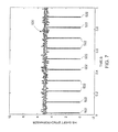
- FIG. 10 is a graphical illustration of exemplary signal processing results 560 generated using the same information received from the accelerometer 256 as is used to generate the line 550 shown in FIG. 9 using the order analysis method described herein.
- the X-axis represents order domain of the signal 550 shown in FIG. 9 and the Y-axis represents the acceleration (in g) output from the accelerometer 256 .
- the signals that are blurred humps in the frequency domain shown in FIG. 9 appear as distinguished peaks 562 - 570 in the order domain shown in FIG. 10 .
- point 562 represents the rotational speed of the high-speed shaft 174 .
- point 564 corresponds to the gearmeshing order, while points 566 , 568 , and 570 , etc., represent higher orders of the gearmeshing order 564 .
- the high-speed shaft 174 has twenty teeth, thus the high-speed gearmeshing order 564 is 20, which means 20 times meshing occurred in one revolution of the high-speed shaft.
- the controller 30 applies the order analysis method to the raw data received from the accelerometer 256 to generate the line 560 shown in FIG. 10 .
- the sidebands around each point 564 , 566 , 568 , 570 , etc. are also easily distinguished enabling an operator or design engineer to identify the sidebands around each peak, which may contain the gear teeth health information. This information may then be utilized by the operator to monitor the health condition of the gearbox 32 .
- the variation due to the shaft speed change has been eliminated. Because the order analysis shown in FIG. 10 is based on the high-speed shaft 174 , the order of the high-speed shaft 174 is exactly at 1 and the high-speed gearmeshing fundamental order is at 20 in this exemplary configuration. Furthermore, the higher orders of the high-speed gearmeshing frequencies are also clearly identifiable.
- an operator may identify gearbox damage by visually inspecting the results shown in FIG. 10 .
- the system 90 may be configured to automatically identify and present potential damage results to an operator.
- the system 90 may be programmed to receive a predetermined index number. The index number representing an index space about each point identified in FIG. 10 , for example.
- the index space may be a percentage of change in a sideband frequency around each point. For example, if the system 90 determines that there is a sideband frequency that is approximately 20% of total energy, the system 90 may generate a visual or audio indication that a potential component failure has occurred or may occur in the near future. The visual or audio indication may also indicate the spread of potential damage in the gearbox 32 .
- FIG. 11 is a zoomed version of the signal 550 shown in FIG. 9 .
- FIG. 12 is a zoomed version of the signal 560 shown in FIG. 10 .
- the conventional power spectrum of the signal 550 produces blurring or distortion around 240 Hz which represents the high-speed gear meshing frequency.
- the accelerometer information is processed with order analysis as discussed above to generate the signal 560
- the order spectrum of the high-speed shaft gear meshing frequency is more clean and identifiable. For example, in addition to the high-speed shaft frequency and higher order frequency harmonics, peaks at 4.46 and 8.84, other orders are clearly shown as marked in FIG. 12 .
- the second stage gearmeshing order (4.4347 order) and second harmonics (8.8694 order) and third harmonics (13.3041 order) are also clearly identifiable.
- the first stage gearmeshing (1.1087 order) is also identifiable, but is small and close to the shaft speed.
- the order analysis methods described herein may be used to improve the identification of damage or potential damage, when the wind turbine 10 is operating at a variable speed or a fixed speed. More specifically, because many bearing and gear features are high orders of the shaft frequency, any slight variation in the shaft speed will influence the power spectrum amplitude at the gearing and bearing condition feature frequency locations. As a result, those feature frequencies are not always at the frequency bins of the power spectrum. Thus, the amplitude of the gear and bearing condition features may vary in the power spectrum.
- the sampling points within a shaft cycle are fixed, thus the sampling point within a feature frequency cycle is also a fixed number, as a result, the feature amplitude is fixed as well.
- FIG. 13 is a graphical illustration of an exemplary speed signal 600 acquired from the tachometer 202 when the high-speed shaft 174 is operating at an approximately constant speed.
- the X-axis represents time and the Y-axis represents the frequency of the shaft speed.
- the high-speed shaft 174 is controlled at a constant speed of approximately 24 Hz or 1440 RPM.
- the speed variation is less than approximately 0.06 Hz, or 3.6 RPM.
- FIG. 14 is a graphical illustration of an exemplary power spectrum 602 generated using the signal 600 shown in FIG. 13 .
- FIG. 15 is a graphical illustration of an exemplary order spectrum 604 generated using the signal 600 shown in FIG. 13 .
- the operator may observe that the magnitude of the power spectrum 604 , at 24 Hz, is very close to the corresponding magnitude from the order spectrum 604 for a first order harmonic 606 . This is as expected because the speed variation at the shaft speed is very small.
- the distortion in the power spectrum 606 at this frequency is relatively small because there is a 0.5 Hz frequency resolution, which results in a frequency bin at 24 Hz.
- the amplitude difference becomes significant, especially at the higher orders.
- the power spectrum magnitude is approximately 45% lower than the order spectrum magnitude (true amplitude).
- This difference between the power spectrum harmonics and the order spectrum harmonics indicates that vibration energy did smear in the power spectrum 602 shown in FIG. 14 , while in the order spectrum 604 , the signal energy is tightly located at the specified order (60 order in this case) as expected from the results of the synchronous sampling technique described above.
- FIG. 16 is a detailed graphical illustration of exemplary results obtained using the conventional power spectrum analysis shown in FIG. 14 .
- FIG. 17 is a detailed graphical illustration of the exemplary results obtained using the order analysis method shown in FIG. 15 .
- the harmonics indicate that the vibration energy is smeared around a point 610 at approximately 1440 Hz in the power spectrum using the conventional power spectrum analysis. While FIG. 17 illustrates that the signal energy at point 610 is tightly located at the specified order using the synchronous sampling method described herein.
- FIG. 18 is a graphical illustration of vibration analysis results 620 for twelve constant speed cases obtained using power spectrum analysis.
- FIG. 18 also illustrates vibration analysis results 622 for twelve constant speed cases obtained using the order analysis method described herein. It should be realized that both the power spectra and order spectra were analyzed using information acquired from the same accelerometer on gearbox 32 . For each result, amplitudes of the high-speed gear meshing response (1 ⁇ HSS GM) and its 2 nd and 3 rd harmonics (2 ⁇ HSS GM and 3 ⁇ HSS GM) were extracted.
- the distribution of the 1 ⁇ HSS GM versus 2 ⁇ HSS GM amplitude from power spectrum and order spectrum are each shown in FIG. 18 , where the vertical axis is the 1 ⁇ HSS GM amplitude and the horizontal axis is the 2 ⁇ HSS GM amplitude.
- the solid dots 630 are the amplitudes extracted from the power spectrum while the circles 632 are the amplitudes extracted using the order spectrum.
- the amplitudes extracted from the order analysis are generally higher and more tightly clustered than those extracted from the conventional power spectrum. This result is made more apparent in higher frequency regions, such as those shown in FIG. 19 , where the distributions of 2 ⁇ HSS GM versus 3 ⁇ HSS GM are plotted.
- a technical effect of the various embodiments is to provide a system that is configured to monitor both the performance of a wind turbine gearbox and also to determine the health of the wind turbine gearbox.
- the system includes various sensors that are coupled to the gearbox. The outputs from the various sensors are input to a controller. Information obtained from various sensors installed in the gearbox may be transmitted to the controller via a wired or wireless connection. Digitized sensor signals are then processed by the controller to extract bearing component health conditions and to assess gearbox performance. The information may also be transmitted to gearbox providers and engineers through a wired or wireless communication devices. Additionally, operators and designers may request actions needed through the communication device and the controller.
- Various embodiments described herein utilize either an actual tachometer signal or a synthesized tachometer signal.
- the tachometer signal is divided into segments based on the rotational position of the shaft to generate a synchronous sampling signal.
- the synchronous sampling signal is formed such that for each rotation there is an equal distance that is not based on time, but is a position of the shaft during rotation.
- An FFT is then applied to the cycle based synchronous sampling signal to generate a graphical illustration of actual or potential gearbox damage.
Abstract
Description
Δt 1 =t i+1 −t i Equation (2); and
Δt 2=60/n Equation (3).
where T is the sampling period. As a result, for bearing and gear dynamic response analysis, the frequency of interest is generally significantly greater than the shaft speed. In other words, the digitization rate is usually several orders of magnitude higher than the shaft speed. Thus, synthesizing errors from the digitization error are negligibly small.
Claims (17)
Priority Applications (2)
| Application Number | Priority Date | Filing Date | Title |
|---|---|---|---|
| US12/847,331 US8364424B2 (en) | 2010-07-30 | 2010-07-30 | System and method for monitoring a wind turbine gearbox |
| PCT/US2011/044316 WO2012015614A2 (en) | 2010-07-30 | 2011-07-18 | System and method for monitoring a wind turbine gearbox |
Applications Claiming Priority (1)
| Application Number | Priority Date | Filing Date | Title |
|---|---|---|---|
| US12/847,331 US8364424B2 (en) | 2010-07-30 | 2010-07-30 | System and method for monitoring a wind turbine gearbox |
Publications (2)
| Publication Number | Publication Date |
|---|---|
| US20120029838A1 US20120029838A1 (en) | 2012-02-02 |
| US8364424B2 true US8364424B2 (en) | 2013-01-29 |
Family
ID=44504192
Family Applications (1)
| Application Number | Title | Priority Date | Filing Date |
|---|---|---|---|
| US12/847,331 Expired - Fee Related US8364424B2 (en) | 2010-07-30 | 2010-07-30 | System and method for monitoring a wind turbine gearbox |
Country Status (2)
| Country | Link |
|---|---|
| US (1) | US8364424B2 (en) |
| WO (1) | WO2012015614A2 (en) |
Cited By (7)
| Publication number | Priority date | Publication date | Assignee | Title |
|---|---|---|---|---|
| US9651443B2 (en) | 2014-06-06 | 2017-05-16 | General Electric Company | System and method for protecting rotary machines |
| US20190154007A1 (en) * | 2016-05-04 | 2019-05-23 | Vestas Wind Systems A/S | Method of identifying a fault in a system of gears in a wind turbine |
| US11002318B2 (en) | 2017-03-28 | 2021-05-11 | Ge Avio S.R.L. | Output assembly for an accessory gearbox of a gas turbine engine |
| US11536202B2 (en) | 2017-03-28 | 2022-12-27 | Ge Avio S.R.L. | Gas turbine engine turning system |
| US11708815B2 (en) | 2021-02-08 | 2023-07-25 | General Electronic Company | System and method for controlling a wind turbine |
| US11774324B2 (en) | 2021-03-12 | 2023-10-03 | General Electric Renovables Espana, S.L. | System and method for detecting actual slip in a coupling of a rotary shaft |
| US11913429B2 (en) | 2021-04-29 | 2024-02-27 | General Electric Renovables Espana, S.L. | System and method for slip detection and surface health monitoring in a slip coupling of a rotary shaft |
Families Citing this family (19)
| Publication number | Priority date | Publication date | Assignee | Title |
|---|---|---|---|---|
| US20120025526A1 (en) * | 2010-07-30 | 2012-02-02 | General Electric Company | System and method for monitoring wind turbine gearbox health and performance |
| US9645046B2 (en) | 2012-12-17 | 2017-05-09 | General Electric Company | Fault detection system and associated method |
| US20150083168A1 (en) * | 2013-09-22 | 2015-03-26 | Us Gov't Represented By Secretary Of The Navy Chief Of Naval Research Onr/Nrl | Liquid solvent spray brush station for surface cleaning in nano-microtronics processing |
| US9797808B2 (en) * | 2014-05-16 | 2017-10-24 | RMCI, Inc. | Diagnosis of gear condition by comparing data from coupled gears |
| WO2016099645A1 (en) * | 2014-12-18 | 2016-06-23 | Sikorsky Aircraft Corporation | Virtual tachometers based on time series filtering |
| CN109416298A (en) | 2016-05-04 | 2019-03-01 | 维斯塔斯风力系统集团公司 | The method for identifying the failure in the gear train in wind turbine |
| KR101863781B1 (en) * | 2016-09-08 | 2018-06-01 | 두산중공업 주식회사 | Apparatus and method for detecting abnormal vibration |
| EP4245992A3 (en) * | 2017-04-13 | 2023-11-08 | NTN Corporation | State monitoring device, state monitoring system, and state monitoring method |
| RU174229U1 (en) * | 2017-08-03 | 2017-10-10 | Александр Николаевич Филин | Gearbox vibration control device |
| US10488372B2 (en) * | 2017-08-16 | 2019-11-26 | General Electric Company | Systems and methods for detecting damage in rotary machines |
| US10935001B2 (en) * | 2017-11-02 | 2021-03-02 | General Electric Company | System and method for monitoring wear on a gearbox of a wind turbine |
| DE102017220179A1 (en) * | 2017-11-13 | 2019-05-16 | Fraunhofer-Gesellschaft zur Förderung der angewandten Forschung e.V. | Apparatus and method for rotationally synchronous monitoring of a rotating element |
| CN110017957B (en) * | 2018-01-10 | 2021-08-31 | 国家能源投资集团有限责任公司 | Synchronous analysis method, device and system |
| CN108240305A (en) * | 2018-03-29 | 2018-07-03 | 珠海市鑫世达测控技术有限公司 | Generator centering monitors system and method |
| EP3644037A1 (en) | 2018-10-26 | 2020-04-29 | Flender GmbH | Improved method of operating transmission |
| EP3951167B1 (en) * | 2019-03-28 | 2024-01-31 | NTN Corporation | Condition monitoring system |
| US11780610B2 (en) * | 2019-11-07 | 2023-10-10 | Ge Aviation Systems Limited | Monitoring of a revolving component employing time-synchronized multiple detectors |
| CN111611943A (en) * | 2020-05-24 | 2020-09-01 | 哈尔滨理工大学 | Gear classification method based on sound analysis |
| CN113358212B (en) * | 2021-06-21 | 2022-09-30 | 重庆理工大学 | Electromechanical fault diagnosis method and system based on relative harmonic order and modeling method |
Citations (12)
| Publication number | Priority date | Publication date | Assignee | Title |
|---|---|---|---|---|
| US5602757A (en) | 1994-10-20 | 1997-02-11 | Ingersoll-Rand Company | Vibration monitoring system |
| US20050096873A1 (en) | 2002-12-30 | 2005-05-05 | Renata Klein | Method and system for diagnostics and prognostics of a mechanical system |
| US20050284225A1 (en) | 2004-06-28 | 2005-12-29 | Huageng Luo | System and method for monitoring the condition of a drive train |
| US7013210B2 (en) | 2001-11-16 | 2006-03-14 | Goodrich Pump & Engine Control Systems, Inc. | Vibration monitoring system for gas turbine engines |
| US7191073B2 (en) | 2003-01-10 | 2007-03-13 | Oxford Biosignals Limited | Bearing anomaly detection and location |
| US20080069693A1 (en) | 2006-08-24 | 2008-03-20 | Olga Malakhova | Method and apparatus of monitoring a machine |
| US20080140349A1 (en) | 2006-12-08 | 2008-06-12 | General Electric Company | Method and system for estimating life of a gearbox |
| US20090093975A1 (en) | 2006-05-01 | 2009-04-09 | Dynamic Measurement Consultants, Llc | Rotating bearing analysis and monitoring system |
| US20090266160A1 (en) * | 2008-04-24 | 2009-10-29 | Mike Jeffrey | Method and system for determining an imbalance of a wind turbine rotor |
| WO2009133161A2 (en) | 2008-04-29 | 2009-11-05 | Romax Technology Limited | Methods, apparatus and computer readable storage mediums for model-based diagnosis of gearboxes |
| US20100071469A1 (en) | 2008-09-22 | 2010-03-25 | General Electric Company | Synthesized synchronous sampling and acceleration enveloping for differential bearing damage signature |
| US20110020122A1 (en) * | 2009-07-24 | 2011-01-27 | Honeywell International Inc. | Integrated condition based maintenance system for wind turbines |
-
2010
- 2010-07-30 US US12/847,331 patent/US8364424B2/en not_active Expired - Fee Related
-
2011
- 2011-07-18 WO PCT/US2011/044316 patent/WO2012015614A2/en active Application Filing
Patent Citations (14)
| Publication number | Priority date | Publication date | Assignee | Title |
|---|---|---|---|---|
| US5602757A (en) | 1994-10-20 | 1997-02-11 | Ingersoll-Rand Company | Vibration monitoring system |
| US7013210B2 (en) | 2001-11-16 | 2006-03-14 | Goodrich Pump & Engine Control Systems, Inc. | Vibration monitoring system for gas turbine engines |
| US20050096873A1 (en) | 2002-12-30 | 2005-05-05 | Renata Klein | Method and system for diagnostics and prognostics of a mechanical system |
| US7191073B2 (en) | 2003-01-10 | 2007-03-13 | Oxford Biosignals Limited | Bearing anomaly detection and location |
| US7912659B2 (en) * | 2004-06-28 | 2011-03-22 | General Electric Company | System and method for monitoring the condition of a drive train |
| US20050284225A1 (en) | 2004-06-28 | 2005-12-29 | Huageng Luo | System and method for monitoring the condition of a drive train |
| US20090093975A1 (en) | 2006-05-01 | 2009-04-09 | Dynamic Measurement Consultants, Llc | Rotating bearing analysis and monitoring system |
| US20080069693A1 (en) | 2006-08-24 | 2008-03-20 | Olga Malakhova | Method and apparatus of monitoring a machine |
| US20080140349A1 (en) | 2006-12-08 | 2008-06-12 | General Electric Company | Method and system for estimating life of a gearbox |
| US20090266160A1 (en) * | 2008-04-24 | 2009-10-29 | Mike Jeffrey | Method and system for determining an imbalance of a wind turbine rotor |
| WO2009133161A2 (en) | 2008-04-29 | 2009-11-05 | Romax Technology Limited | Methods, apparatus and computer readable storage mediums for model-based diagnosis of gearboxes |
| US20100071469A1 (en) | 2008-09-22 | 2010-03-25 | General Electric Company | Synthesized synchronous sampling and acceleration enveloping for differential bearing damage signature |
| US7930111B2 (en) * | 2008-09-22 | 2011-04-19 | General Electric Company | Synthesized synchronous sampling and acceleration enveloping for differential bearing damage signature |
| US20110020122A1 (en) * | 2009-07-24 | 2011-01-27 | Honeywell International Inc. | Integrated condition based maintenance system for wind turbines |
Non-Patent Citations (1)
| Title |
|---|
| Search Report from corresponding PCT Application No. PCT/US2011/044316 dated Aug. 16, 2012. |
Cited By (8)
| Publication number | Priority date | Publication date | Assignee | Title |
|---|---|---|---|---|
| US9651443B2 (en) | 2014-06-06 | 2017-05-16 | General Electric Company | System and method for protecting rotary machines |
| US20190154007A1 (en) * | 2016-05-04 | 2019-05-23 | Vestas Wind Systems A/S | Method of identifying a fault in a system of gears in a wind turbine |
| US11047364B2 (en) * | 2016-05-04 | 2021-06-29 | Vestas Wind Systems A/S | Method of identifying a fault in a system of gears in a wind turbine |
| US11002318B2 (en) | 2017-03-28 | 2021-05-11 | Ge Avio S.R.L. | Output assembly for an accessory gearbox of a gas turbine engine |
| US11536202B2 (en) | 2017-03-28 | 2022-12-27 | Ge Avio S.R.L. | Gas turbine engine turning system |
| US11708815B2 (en) | 2021-02-08 | 2023-07-25 | General Electronic Company | System and method for controlling a wind turbine |
| US11774324B2 (en) | 2021-03-12 | 2023-10-03 | General Electric Renovables Espana, S.L. | System and method for detecting actual slip in a coupling of a rotary shaft |
| US11913429B2 (en) | 2021-04-29 | 2024-02-27 | General Electric Renovables Espana, S.L. | System and method for slip detection and surface health monitoring in a slip coupling of a rotary shaft |
Also Published As
| Publication number | Publication date |
|---|---|
| US20120029838A1 (en) | 2012-02-02 |
| WO2012015614A2 (en) | 2012-02-02 |
| WO2012015614A3 (en) | 2012-11-01 |
Similar Documents
| Publication | Publication Date | Title |
|---|---|---|
| US8364424B2 (en) | System and method for monitoring a wind turbine gearbox | |
| US20120025526A1 (en) | System and method for monitoring wind turbine gearbox health and performance | |
| EP1760311B1 (en) | Method and apparatus for condition-based monitoring of wind turbine components | |
| KR101764540B1 (en) | Vibration Monitoring and Diagnosis System for Wind Turbine | |
| Villa et al. | Statistical fault diagnosis based on vibration analysis for gear test-bench under non-stationary conditions of speed and load | |
| US7417332B2 (en) | Method and apparatus of monitoring a machine | |
| US9915585B2 (en) | Wear-monitoring of a gearbox in a power station | |
| Yoon et al. | On the use of a single piezoelectric strain sensor for wind turbine planetary gearbox fault diagnosis | |
| CA2889107C (en) | Wind turbine diagnostic device for generator components | |
| US9459179B2 (en) | Method and device for monitoring a drive train of a wind power plant | |
| JP2017525891A (en) | Drive system early error detection method, early error detection system, wind generator with early error detection system, and use of early error detection system | |
| KR101358397B1 (en) | Fault detection appaturas and method for wind turbin base on acceleration sensor and output power | |
| KR102226971B1 (en) | Method for fault diagnosis based on multiple variables and apparatus using the method | |
| EP3819607A1 (en) | Monitoring of a revolving component employing time-synchronized multiple detectors | |
| JP2017207435A (en) | Abnormality diagnostic method | |
| JP2017181267A (en) | Ball bearing diagnostic device | |
| EP3317628B1 (en) | A method and a device for determining torsional deformation in a drivetrain | |
| CN110219816A (en) | Method and system for Fault Diagnosis of Fan | |
| Gutierrez Santiago et al. | Input torque measurements for wind turbine gearboxes using fiber optical strain sensors | |
| JP6577394B2 (en) | Abnormality diagnosis equipment for wind power generation facilities | |
| CN110455528B (en) | Method and system for planetary gear damage diagnosis | |
| Franco-Piña et al. | Real time conditioning monitoring for failure prediction | |
| CN113669214A (en) | Method and system for detecting planet-level running state of wind power gear box and storage medium | |
| Luo et al. | Synchronous Analysis in Wind Turbine Gearbox Condition Monitoring |
Legal Events
| Date | Code | Title | Description |
|---|---|---|---|
| AS | Assignment |
Owner name: GENERAL ELECTRIC COMPANY, NEW YORK Free format text: ASSIGNMENT OF ASSIGNORS INTEREST;ASSIGNORS:LUO, HUAGENG;HALLMAN, DARREN LEE;HEDEEN, ROBERT;AND OTHERS;REEL/FRAME:024768/0684 Effective date: 20100727 |
|
| AS | Assignment |
Owner name: GENERAL ELECTRIC COMPANY, NEW YORK Free format text: ASSIGNMENT OF ASSIGNORS INTEREST;ASSIGNOR:RICHTER, DENNIS;REEL/FRAME:025096/0317 Effective date: 20100930 |
|
| FEPP | Fee payment procedure |
Free format text: PAYOR NUMBER ASSIGNED (ORIGINAL EVENT CODE: ASPN); ENTITY STATUS OF PATENT OWNER: LARGE ENTITY |
|
| STCF | Information on status: patent grant |
Free format text: PATENTED CASE |
|
| CC | Certificate of correction | ||
| FPAY | Fee payment |
Year of fee payment: 4 |
|
| AS | Assignment |
Owner name: GE GLOBAL SOURCING LLC, CONNECTICUT Free format text: ASSIGNMENT OF ASSIGNORS INTEREST;ASSIGNOR:GENERAL ELECTRIC COMPANY;REEL/FRAME:047736/0140 Effective date: 20181101 |
|
| FEPP | Fee payment procedure |
Free format text: MAINTENANCE FEE REMINDER MAILED (ORIGINAL EVENT CODE: REM.); ENTITY STATUS OF PATENT OWNER: LARGE ENTITY |
|
| LAPS | Lapse for failure to pay maintenance fees |
Free format text: PATENT EXPIRED FOR FAILURE TO PAY MAINTENANCE FEES (ORIGINAL EVENT CODE: EXP.); ENTITY STATUS OF PATENT OWNER: LARGE ENTITY |
|
| STCH | Information on status: patent discontinuation |
Free format text: PATENT EXPIRED DUE TO NONPAYMENT OF MAINTENANCE FEES UNDER 37 CFR 1.362 |
|
| FP | Lapsed due to failure to pay maintenance fee |
Effective date: 20210129 |