US8390508B1 - Generating radar cross-section signatures - Google Patents
Generating radar cross-section signatures Download PDFInfo
- Publication number
- US8390508B1 US8390508B1 US12/753,982 US75398210A US8390508B1 US 8390508 B1 US8390508 B1 US 8390508B1 US 75398210 A US75398210 A US 75398210A US 8390508 B1 US8390508 B1 US 8390508B1
- Authority
- US
- United States
- Prior art keywords
- spectrum
- radar
- chaff
- objects
- macro
- Prior art date
- Legal status (The legal status is an assumption and is not a legal conclusion. Google has not performed a legal analysis and makes no representation as to the accuracy of the status listed.)
- Active, expires
Links
Images


Classifications
-
- G—PHYSICS
- G01—MEASURING; TESTING
- G01S—RADIO DIRECTION-FINDING; RADIO NAVIGATION; DETERMINING DISTANCE OR VELOCITY BY USE OF RADIO WAVES; LOCATING OR PRESENCE-DETECTING BY USE OF THE REFLECTION OR RERADIATION OF RADIO WAVES; ANALOGOUS ARRANGEMENTS USING OTHER WAVES
- G01S7/00—Details of systems according to groups G01S13/00, G01S15/00, G01S17/00
- G01S7/02—Details of systems according to groups G01S13/00, G01S15/00, G01S17/00 of systems according to group G01S13/00
- G01S7/41—Details of systems according to groups G01S13/00, G01S15/00, G01S17/00 of systems according to group G01S13/00 using analysis of echo signal for target characterisation; Target signature; Target cross-section
- G01S7/411—Identification of targets based on measurements of radar reflectivity
- G01S7/412—Identification of targets based on measurements of radar reflectivity based on a comparison between measured values and known or stored values
Definitions
- a radar system emits radio waves that are reflected by an object in a form of a reflected signal that is detected by the radar system. Based on the round trip time duration and the angle of the reflected signal, the location of the object may be determined. In training scenarios, instead of using actual objects, it is more practical and cost effective to use simulated radar objects.
- the simulated radar objects may be generated using radar signature modeling tools that emulate the radar object.
- Chaff is used by aircraft to evade hostile forces or by ballistic missiles to mask the objects in the missile complex.
- the chaff is released by an aircraft and used to create radar objects to draw enemy fire away from the aircraft.
- chaff includes metallic structures that are easily detected by radar.
- a missile 12 includes a chaff dispenser 14 .
- the chaff dispenser releases (dispenses) chaff packages 16 a , 16 b , 16 c (called herein “pucks”) into the air.
- the pucks are dispensed at different times.
- the pucks 16 a - 16 c disperse a cloud of chaff 18 .
- a radar 20 detects the chaff from the pucks 16 a - 16 c and the missile 12 so that it appears to a user there are more missiles so that more enemy munitions are directed towards the chaff than the missile.
- a method to generate radar cross section (RCS) signatures includes determining a spectrum of an object and using the spectrum of the object to generate RCS signatures of a plurality of objects.
- an apparatus to generate radar cross section (RCS) signatures includes circuitry to determine a spectrum of an object; and use the spectrum of the object to generate RCS signatures of a plurality of objects.
- an article includes a machine-readable medium that stores executable instructions to generate radar cross section signatures (RCS). The executable instructions cause a machine to determine a spectrum of an object and use the spectrum of the object to generate RCS signatures of a plurality of objects.
- One or more of the aspects above may include one or more of the following features.
- Using the spectrum of the object to generate RCS signatures of a plurality of objects may include using the spectrum of the object that includes chaff to generate RCS signatures of a plurality of objects that includes chaff.
- Using the spectrum of the object that includes chaff to generate RCS signatures of a plurality of objects that includes chaff may include interpolating time, selecting frequencies to match a center frequency and bandwidth of a radar pulse, resampling to frequency sampling of radar to match a range bin size and shifting and applying trajectory phase and scaling.
- FIG. 1A is a view of a missile releasing chaff.
- FIG. 1B is a drawing of coordinate systems of importance for this process.
- FIG. 1C is a drawing of a radar antenna showing four quadrants and the different line of sight distances from them used in phase comparison monopulse.
- FIG. 2 is a flowchart of an example of a process to generate radar cross section (RCS) signatures.
- RCS radar cross section
- FIG. 3 is a flowchart of an example of a process to generate RCS signatures for multiple pucks of chaff.
- FIG. 4 is a diagram depicting range determination.
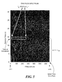
- FIG. 5 is an example of spectrum of one puck of chaff.
- FIGS. 6A to 6C are a set of drawings of sequences of radar pulses in the time domain.
- FIG. 7 is a block diagram of an example of a computer on which the process of FIG. 4 may be implemented.
- Prior art radar cross section (RCS) signature prediction models are used to generate radar chaff signatures for each scenario and stored in lookup tables.
- a single database for multiple scenarios is not practical to generate all potential scenarios and waveforms for chaff.
- the alternative approach to a massive database generation for chaff is to predict RCS signature in real-time using a much smaller lookup table.
- the methods described herein provide a technique to generate chaff RCS signatures, for example, in real-time, while retaining a high-fidelity model.
- the Acceleration Method is a technique to quickly generate RCS signatures for the multiple puck and dispenser activities.
- Emulating chaff signatures for the multiple puck/dispenser activities has been achieved by combining corresponding puck signatures, extracted from single puck's signature database, after linear phase shifts according to scenario trajectories and radar beam scheduling.
- chaff While the particular examples described herein focus on chaff, the techniques described herein may be applied to other types of objects like reentry vehicles and rocket bodies. The focus is on chaff in this description because of the large numbers of pieces of chaff that can be deployed (e.g., thousands or tens of thousands deployed) whereas for other object types (e.g., reentry vehicles, rocket bodies and so forth) the numbers are typically on the order of ones to tens.
- a Final Look-up Table (LUT) of chaff is determined and a chaff cloud trajectory is generated.
- the Final LUT may be substituted with a target LUT of target scattering data as a function of aspect angle and chaff puck trajectory information substituted with target Center of Gravity (CG) trajectory and rotational orientation information.
- CG Center of Gravity
- Fourier transformation provides a frequency spectrum with a peak at f.
- LFM Linear Frequency Modulation
- the convention is to use the intermediate radar pulse, prior to Fourier Transformation, as a frequency domain signal.
- the time reference is the beginning or middle of the pulse.
- a Fourier transform performed on this signal will have a peak at ⁇ in the resulting spectrum that represents the target's time offset from the pulse's reference time.
- the sign convention of the signal varies from radar to radar so that one will see the use of a Fourier transform or an inverse Fourier transform depending on the radar's convention.
- This final Fourier transform to complete ‘Pulse Compression’ can be a multi-step process with windowing and shifts such that any implementation of this algorithm has to match the specific radar's final Fourier transform process and sign convention.
- This electromagnetic pulse reflects off the target and returns to the radar.
- the received pulse On arrival at the radar the received pulse is mixed with the conjugate of a duplicate of the transmitted pulse that is triggered at the expected time of arrival of the reflected pulse and has used a stable oscillator as carrier frequency reference (f c ).
- the resulting deramped signal then has the form exp(i2 ⁇ (B ⁇ roff t/T+f c ⁇ rt )) ignoring Doppler effects.
- the Doppler effect on the frequency slope is pre-compensated on transmit or receive and the residual effects are negligible.
- the Doppler shift component due to the carrier frequency gives rise to the Range Doppler Coupling (RDC) effect and is treated as a time/range offset in later processing and may be pre-compensated.
- ⁇ rt is the round trip time for the pulse from the radar to the target and back for a coherent radar.
- ⁇ roff is a time offset between the time when the reflected pulse arrived at the radar and the reference pulse was triggered.
- the time offset, ⁇ roff would be zero if the radar could determine exactly where the target was as a function time and choose to trigger the reference pulse appropriately.
- N # of samples
- ⁇ rt 2R(t)/c
- R(t) is the target center of gravity slant range from the radar as a function of time
- c is the speed of light in vacuum.
- the actual term is (2R(t)+ ⁇ R)/c for Phase Comparison Monopulse with ⁇ R depending on which quadrant the antenna phase data is processed from and where c is the speed of light.
- a phase correction is applied for this trajectory motion.
- an estimate of target e.g., chaff puck
- center of gravity (CG) location as a function of time pulse to pulse phase variation is reduced to scatterer motion about the CG by this phase correction.
- the phase corrected frequency domain LFM signal to generate the Final LUT is of the form: S n exp( i 2 ⁇ ( B ⁇ roff n /( N ⁇ 1)+ f c ⁇ roff )), where the phase term depends on ⁇ roff , the same as the frequency varying time offset.
- This time offset is the time offset of a scatterer/chaff piece from the CG of the target/chaff puck, the round trip time of an EM wave from the scatterer to the CG along the direction defined by the radar line of sight.
- FIG. 1B shows a radar located on the surface of the earth.
- coordinate systems there are many variations of coordinate systems one could employ for this problem. Of note are Cartesian coordinate systems centered in the earth, centered at the radar antenna with z axis vertical and centered at the radar antenna center with z axis perpendicular to a plane tangent to the antenna.
- RAE Range
- Azimuth the angle of the object relative to the radar measured clockwise from north
- elevation is the angle of the object relative to the radar measured up from the horizontal.
- RUV, Range, U, V is a phased array radar coordinate system
- Range is the distance from the antenna center to the object
- U is the direction cosine of the line of sight of the object from the radar with the transverse direction of the antenna.
- x-axis of FIG. 1C V is the direction cosine of the line of sight of the object from the radar with the vertical direction of the antenna.
- y-axis of FIG. 1C is the direction cosine of the line of sight of the object from the radar with the vertical direction of the antenna.
- phase centers q 1 , q 2 , q 3 , q 4 .
- phase centers can be offset from the physical antenna by appropriate relative phasing of transmit and receive processing.
- all four quadrants of the radar antenna transmit energy.
- the resulting signal arrives at the target as if it was transmitted as a point source located at the antenna center, t c .
- the radar energy is reflected off the target and returns to the radar antenna.
- Each of the four quadrants operates as its own receiver channel that is centered in the quadrant.
- B/c(2 ⁇ R tc + ⁇ R tqs )n/(N ⁇ 1) is not substantially affected since ⁇ R tqs is less than 1/10 of the
- the ratios ⁇ ⁇ / ⁇ and ⁇ ⁇ / ⁇ then give the appropriate monopulse ratios for computing the horizontal ( ⁇ ) and vertical ( ⁇ ) angle offsets of the target from the beam center.
- the symbol q which denoted the quadrant has been changed to ⁇ to denote the alpha channel which corresponds to the sums and differences of the different quadrants in the horizontal, ⁇ would correspond to the sums and differences of the different quadrants in the vertical.
- radar signature data is a radar pulse prior to any detection processing.
- I and Q data is a radar pulse prior to any detection processing, where I is the real component and Q is the imaginary component.
- B represents radar pulse bandwidth, and is the span of wave frequencies in the electromagnetic energy processed in the receive radar pulse.
- f c represents a center frequency of the transmitted radar pulse.
- PW is a pulse width of the radar pulse (duration in time).
- Monopulse is a term describing the collection and processing of data and the data itself to support the measurement of angular offsets of objects in radar data.
- RDC Range Doppler Coupling effect in LFM radar data and is the apparent shift in range (time) of an object due to Doppler shift of radar carrier frequency given by object range rate multiplied by PW*f c /B.
- R range, slant range.
- U is the direction cosine of the line of sight of the object from the radar with the transverse direction of the antenna.
- V is the direction cosine of the line of sight of the object from the radar with the vertical direction of the antenna.
- ⁇ r bin size c/(2B) (N s ⁇ 1)/(N fft ⁇ 1). Distance spanned between one range bin and another in the time domain radar pulse.
- B is pulse bandwidth
- c speed of light
- N s is the number of samples of the pulse in the frequency domain
- N fft is the size of the Fourier Transform applied to the pulse).
- ⁇ Sum of m phase centers channel data
- ⁇ ⁇ Appropriate sum and difference of m phase centers' data is beta difference channel pulse
- the Final LUT table is generated that includes the radar LFM response of a particular instance of a chaff cloud (e.g., a single chaff puck or a dispenser of multiple pucks) centered in the radar beam and radar range window. This is done for the full operational bandwidth of the radar, for a sequence of radar pulses at a fixed PRF (Pulse Repetition Frequency) from the chaff deployment time until it is expected that, for the scenarios of use, the chaff cloud will exit the FOV (Field of View) or move beyond the detectable range for the radar.
- PRF Pulse Repetition Frequency
- the Final LUT generation process accesses a chaff dipole electromagnetic Scattering LUT.
- This Scattering LUT would typically be generated with Method of Moments electromagnetic scattering code and stores the scattering amplitude and phase for an individual chaff piece as a function of frequency and angle of incidence of the radar beam.
- radar RCS Radar Cross Section prediction code to generate a LUT (called herein a “Scattering LUT”) of the amplitude and phase of the monostatic reflected electromagnetic energy from the radar for a single piece of chaff as a function of frequency and aspect angle is used generate the Final LUT.
- the aspect angle is the angle between the incident radar electromagnetic wave and the vector normal to the long axis (axis of symmetry assuming a wire dipole, this can be easily generalized to asymmetric objects) of the chaff piece.
- the amplitude and phase are generated for a sampling of frequencies between the minimum and maximum operating frequency of the radar, for a sampling of chaff object orientations (aspect angles) relative to the radar line of sight.
- the Scattering LUT can be reused for multiple chaff puck types and scenarios. A different Scattering LUT is required for each chaff type (Different chaff piece types) to be simulated.
- the Final LUT (A single instance of radar data of a chaff puck, one could generate several Final LUTs and mix and match at random to introduce additional statistical variation of the chaff) is used in a real time or near real time radar simulation as the reference data to insert the chaff data into radar pulses as the pulses are placed by the real time tracking and scheduling algorithms of the radar software. This is accomplished by appropriate interpolation, time shifting and application of trajectory phase to be described in more detail later.
- This approach retains a very high fidelity representation of chaff data and reduces the real time computations from being done thousands or tens of thousands of times to a few times per radar pulse and allows for Monte Carlo runs to be performed with different target trajectories and statistical variation of the chaff cloud trajectories using the radar real time tracking, discrimination and pulse scheduling algorithms.
- the Final LUT is used to generate multiple chaff pucks.
- radar pulses with chaff from multiple chaff pucks along various trajectory offsets from the baseline complex trajectory can be produced with limited computation load.
- This process can be applied to multiple macro-objects of the same type (see processing block 230 of FIG. 2 ). For example, if the macro-object is a chaff dispenser that holds chaff pucks, then the RCS signatures of multiple chaff dispensers and their chaff may be determined as a way to reduce computational load further.
- the appropriate pulses from the Final LUT are selected based on time from the beginning of dispensing of chaff from each puck.
- the difference between the radar pulse time and the puck dispensing start time is used to select pulses from just before and just after the radar pulse time.
- the appropriate frequency samples from these selected Final LUT pulses are selected for the current pulse's center frequency and bandwidth. This data is used to interpolate to the time of the radar pulse under construction and interpolated in frequency to ensure a match in radar range bin size with the radar pulse's range bin size.
- the radar pulse's pulse width (The time duration of a pulse) and the Analog to Digital converter rate that produces the frequency sampling that is the equivalent of what is in the Final LUT.
- the radar will generate a specific number of frequency samples for a given pulse width and then zero pad (Zero padding is the appending of zeros to a data vector until the data vector has length that is a power of two in preparation of applying a FFT.) the data up to a power of two in preparation for application of a Fast Fourier Transform (FFT) to complete pulse compression.
- FFT Fast Fourier Transform
- the frequency data is resampled from the Final LUT such that after zero padding and FFT the range bin size is the same as the radar pulse being added to the simulated chaff.
- the Final LUT may have substantially fewer or substantially greater number of frequency samples than the radar pulse. (e.g., equivalent to coming from a longer or shorter pulse width pulse, but as long as B (bandwidth) and range bin size are matched the final data combination is valid).
- the single puck radar signatures will in general be sampled at a different frequency sampling interval than the radar pulse and have a different number of frequency samples within the pulse's bandwidth.
- N L s can be more than two times greater or more than two times smaller than N.
- This data is then time shifted (e.g., shifted in relative range within the pulse) based on the difference between the radar scheduled pulse nominal range and the particular chaff puck centroid trajectory (Remember the Final LUT had the chaff centered in the radar range window as if the radar knew exactly where to place the range window).
- the trajectory phase of the puck centroid is applied to the data at this point (Since each chaff piece has a phase reference to the chaff puck centroid in the LUT, this combined with the chaff puck centroid trajectory phase produces the appropriate trajectory phase for each chaff piece.
- This process can be applied to produce monopulse data to provide high fidelity radar angle measurements.
- a full implementation for a phase comparison monopulse system would produce four Final LUT's for each of four phase center offsets (Assuming four is the appropriate number for the modeled radar) by doing the Final LUT generation process for each phase center, but with the radar reference location shifted for each to that particular monopulse channel phase center. Then the real time process is performed for each of the four monopulse channel phase center offsets and appropriate sum and difference channel data is produced for each radar pulse.
- An initial implementation includes the real time portion described herein, but not the four Final LUT's. The four Final LUT's for highest fidelity monopulse data is more closely tied to the trajectories that the data was created for.
- the approach is based on recognition that for each monopulse channel the outgoing EM wave's radar slant range, R, is considered to be the same for all channels, which is the equivalent of a single transmitter located at the mid point of the monopulse channel locations. Then for each channel the receive slant range is slightly different, R+ ⁇ R q . Then when the Acceleration Method range shift is computed for the q th channel, 2R+ ⁇ R q is used for computation of the time (range) shift of the chaff pulse and for the trajectory phase addition.
- one example of determining RCS signatures of objects is a process 200 .
- the approach for generating the Final LUT to be used in the real time processing is as follows.
- a sequence of radar pulses of the form of a deramped LFM waveform frequency spectrum is determined for an object (Chaff Puck) ( 210 ).
- This LFM is the equivalent of a radar LFM waveform that has the full operational bandwidth of the radar and operational center frequency of the radar.
- the chaff cloud centroid is centered in the radar pulse range window.
- Centering means the chaff cloud centroid trajectory is the radar range window center reference for each simulated pulse, the final sequence of simulated pulses is exactly the aligned and phase corrected data one would expect if the radar had placed a sequence of wideband LFM pulses on the chaff puck centroid and applied a trajectory phase correction based on the puck trajectory, but it is stored in the frequency domain.
- the Final LUT is made up of radar pulses in the frequency domain.
- S k (m,n) is the k th chaff piece scattering amplitude and phase from the Scattering LUT for chaff piece orientation at m th time at n th frequency.
- a 6 degree of freedom trajectory (6-DOF, CG trajectory+rotational motion of piece) is flown for each chaff piece.
- the radar slant range offset of the chaff piece is computed from the chaff puck trajectory and the difference in radar slant range (Line of sight) between the chaff puck and each chaff piece is computed.
- the PRF (Pulse Repetition Frequency) of the Final LUT should be high enough that the chaff cloud expansion rate is still within the unambiguous Doppler window if one expects to use Doppler processing.
- the radar pulse range window should be large enough to encompass the whole chaff cloud at the end of the data interval for true fidelity also.
- This one LUT is then useful for multiple Monte Carlo runs of the same baseline target complex trajectory and radar location. For example, threat object and chaff puck trajectory offsets can be varied around this baseline trajectory. This limitation of same baseline target complex trajectory and radar location may be relaxed somewhat also.
- signatures of other objects of the same type may be determined ( 220 ). For example, if the spectrum is of one chaff puck, then the spectrum of one chaff puck may be applied to multiple chaff pucks. The process of applying to cover multiple objects of the same type is applied to macro-objects ( 230 ). For example, if the macro-object is a chaff dispenser that holds chaff pucks, then the RCS signatures of multiple chaff dispensers and their chaff may be determined.
- an example of a process to perform processing block 220 with respect to chaff, and in particular, determining RCS values for k pucks of chaff is a process 300 .
- a frequency response of a dipole e.g., cylindrical
- the spectrum of one puck or dispenser may be generated from the Scattering LUT.
- This spectrum, a sequence of radar signature data pulses, is the Final LUT used in the real time process. This final LUT is accessed to generate radar pulses with multiple pucks inserted in real time thereby accelerating the high fidelity simulation capability timeline.
- simulating chaff signatures for multiple puck/dispenser activities may be achieved in real time by applying linear phase shifts, (e.g., according to scenario trajectories and radar beam scheduling), to pre-computed single puck radar signatures from the Final LUT and then coherently summing them with simulated real time radar pulses.
- linear phase shifts e.g., according to scenario trajectories and radar beam scheduling
- Radar data is obtained ( 302 ). For example for a time t, simulated I & Q radar pulse data for other targets within the radar beam is obtained; Radar beam placement data, R; U; V; Rd; Radar beam parameters, bandwidth, B; center frequency, f c ; pulse width, PW; scaling, S c ; and the pulse's range bin size, ⁇ r bin size .
- Puck data is obtained ( 304 ). For example, for each puck a trajectory and dispense time information is obtained. For example, for a k-th puck, the initial puck dispense time for the k-th puck, t 0,k , is obtained and a slant range, R k is obtained.
- k th chaff puck trajectory is propagated to current radar pulse time.
- the slant range R k from the radar antenna center to the chaff puck is determined.
- R k is measured from an origin 402 of a radar (Antenna center) to the k-th puck 404 along a direction of the radar beam 408 .
- a slant range difference, ⁇ R k is the difference of the slant range, R k , of the chaff puck and the reference range of a radar pulse beam 408 .
- a puck pulse is selected for time, t ( 310 ).
- a frequency domain simulated pulse is obtained from a look-up table, the Final LUT, representing a spectrum of a puck shown in FIG. 5 .
- the frequency domain simulated pulse to be added into the radar pulse is interpolated to the current time offset of the radar pulse by using the Final LUT pulses from just before and just after the current pulse time ( 320 ).
- an interpolated time, ⁇ t k is equal to time, t, minus the dispense time of the k-th puck, t 0,k .
- the dispense time corresponds to the time the chaff is first dispensed from the puck.
- the frequencies are selected ( 330 ).
- frequency bins are selected to match the current radar pulse's center frequency, f c , and bandwidth, B.
- B bandwidth
- f c ⁇ B/2 to f c +B/2.
- a resampling is performed to frequency sampling of the radar to match range bin size, ⁇ r bin size ( 340 ).
- a range shift, trajectory phase and scaling for each radar phase center is applied ( 350 ).
- the chaff puck data is shifted from the center of the pulse, as stored in the Final LUT, to the offset due to the radar's pulse placement, adding in the trajectory phase component of the chaff puck to the pulse from the Final LUT data and then scaling for beam shape, atmospheric and other losses and unit conversion from meters for chaff signal amplitude as stored in the Final LUT to the radar internal signal processing units.
- the radar LFM signal model is exp(i2 ⁇ (B ⁇ roff n/(N s ⁇ 1)+f c ⁇ rt )).
- the fractional portion and integer portion, ⁇ R fmk and ⁇ R ik , of ( ⁇ R k + ⁇ R mk )/2 modulo ⁇ r bin size are computed where
- S c is the scaling for losses and unit conversion and w n the window, applied in preparation for Fourier transformation, for sidelobe reduction in the time domain.
- 2 ⁇ (R k +R mrtk )/ ⁇ c is the trajectory phase term for the chaff puck.
- a summation is performed ( 360 ). For example, sums and differences are performed to form ⁇ , ⁇ ⁇ , ⁇ ⁇ data, this is the sum signal and monopulse information, so angular information can be measured on targets.
- FIGS. 6A to 6C show sequences of radar pulses in the time domain.
- FIG. 6A shows aligned chaff cloud data as stored in the Final LUT.
- FIG. 6B shows the chaff cloud data shifted based on a radar's reference pulse alignment as done in the Real Time Process.
- FIG. 6C shows the chaff cloud with wrapping at the end of the data if the shift done in the Real Time Process were not broken into integer and fractional parts.
- the following pseudo code may be used to determine RCS for chaff. References in the pseudo code are made to process 300 .
- S c is scaling for beam shape, atmospheric and other losses and scaling.
- a computer 700 includes a processor 722 and a volatile memory 724 , a non-volatile memory 726 (e.g., a hard disk).
- the non-volatile memory 726 stores computer instructions 734 , an operating system 736 and data 738 including a one puck spectrum lookup table 750 (e.g., Final Look-Up Table), radar data 760 and puck data 770 .
- the radar data includes I & Q, time, R, U, V, B, f c , PW Scaling, and bin size.
- the puck data 770 includes puck dispense time and puck trajectory.
- the computer instructions 734 are executed by the processor 722 out of volatile memory 724 to perform all or part of the process 300 .
- Process 300 is not limited to use with the hardware and software of FIG. 7 ; they may find applicability in any computing or processing environment and with any type of machine or set of machines that is capable of running a computer program.
- Process 300 may be implemented in hardware, software, or a combination of the two.
- Process 300 may be implemented in computer programs executed on programmable computers/machines that each includes a processor, a storage medium or other article of manufacture that is readable by the processor (including volatile and non-volatile memory and/or storage elements), at least one input device, and one or more output devices.
- Program code may be applied to data entered using an input device to perform process 300 and to generate output information.
- the system may be implemented, at least in part, via a computer program product, (e.g., in a machine-readable storage device), for execution by, or to control the operation of, data processing apparatus (e.g., a programmable processor, a computer, or multiple computers)).
- data processing apparatus e.g., a programmable processor, a computer, or multiple computers
- Each such program may be implemented in a high level procedural or object-oriented programming language to communicate with a computer system.
- the programs may be implemented in assembly or machine language.
- the language may be a compiled or an interpreted language and it may be deployed in any form, including as a stand-alone program or as a module, component, subroutine, or other unit suitable for use in a computing environment.
- a computer program may be deployed to be executed on one computer or on multiple computers at one site or distributed across multiple sites and interconnected by a communication network.
- a computer program may be stored on a storage medium or device (e.g., CD-ROM, hard disk, or magnetic diskette) that is readable by a general or special purpose programmable computer for configuring and operating the computer when the storage medium or device is read by the computer to perform process 300 .
- Process 300 may also be implemented as a machine-readable storage medium, configured with a computer program, where upon execution, instructions in the computer program cause the computer to operate in accordance with process 300 .
- process 300 is not limited to the specific processing order of FIG. 3 . Rather, any of the processing blocks of FIG. 3 may be re-ordered, combined or removed, performed in parallel or in serial, as necessary, to achieve the results set forth above.
- the processing blocks in FIG. 3 associated with implementing the system may be performed by one or more programmable processors executing one or more computer programs to perform the functions of the system. All or part of the system may be implemented as, special purpose logic circuitry (e.g., an FPGA (field programmable gate array) and/or an ASIC (application-specific integrated circuit)).
- special purpose logic circuitry e.g., an FPGA (field programmable gate array) and/or an ASIC (application-specific integrated circuit)
Abstract
Description
exp(i2π(Bτ roff n/(N−1)+f cτrt)), n={−N/2 to N/2},
which is considered to be the LFM frequency domain radar signal and is the final form of the simulated pulse that is added into the radar data.
S nexp(i2π(Bτ roff n/(N−1)+f cτroff)),
where the phase term depends on τroff, the same as the frequency varying time offset. This time offset is the time offset of a scatterer/chaff piece from the CG of the target/chaff puck, the round trip time of an EM wave from the scatterer to the CG along the direction defined by the radar line of sight. It has a correspondence to the scatterer range offset from the pulse's reference range of τroff=2ΔRroff/c. The actual term is τroff=(2ΔRroff+δR)/c for Phase Comparison Monopulse with δR depending on which quadrant of antenna phase data is processed from.
S qs=exp(i2πB/c(2ΔR tc +δR tqs)n/(N−1)+i2π(2R tc +δR tqs)/λ)
The frequency dependent term, B/c(2ΔRtc+δRtqs)n/(N−1), is not substantially affected since δRtqs is less than 1/10 of the range resolution. In the time domain this quadrant's return is then, sqs=Aexp(i2π(2Rtc+δRtqs)/λ)). The phase term is altered by 2πδRtqs/λ and is the effect of interest in capturing a measurement of the angle offset of the target from the beam center. One determines the sums and differences:
Δα =S q1 +S q2 −S q3 −S q4,
Δβ =S q1 +S q3 −S q1 −S q4 and
Σ=S q1 +S q2 +S q3 +S q4.
After a Fourier transformation of these signals to the time domain, the ratios Δα/Σ and Δβ/Σ then give the appropriate monopulse ratios for computing the horizontal (α) and vertical (β) angle offsets of the target from the beam center. One can see this easily when the difference between the received time domain signals from two phase centers (e.g., 1 and 3) is divided by the sum of the two to form the monopulse input for the target range bin, the resulting form is, i tan(2πδRtα/λ)=i tan(2πdα/λδθt) (i=√−1) with dα the distance from the array center to the quadrant's phase center. The symbol q which denoted the quadrant has been changed to α to denote the alpha channel which corresponds to the sums and differences of the different quadrants in the horizontal, β would correspond to the sums and differences of the different quadrants in the vertical.
s f(n,m)=τk S k(m,n)exp(i2π(Bτ(m)roff
Sum over k is sum over chaff pieces' (scatterers') radar slant range offset from chaff puck CG at mth time, n is pulse frequency sample index, n={−N/2 to N/2}. Sk(m,n) is the kth chaff piece scattering amplitude and phase from the Scattering LUT for chaff piece orientation at mth time at nth frequency. A 6 degree of freedom trajectory (6-DOF, CG trajectory+rotational motion of piece) is flown for each chaff piece. The radar slant range offset of the chaff piece is computed from the chaff puck trajectory and the difference in radar slant range (Line of sight) between the chaff puck and each chaff piece is computed. (τ(m)roff
| Algorithm Pseudo Code |
| Offline |
| Construct |
| Scattering LUT |
| Final LUT |
| Real Time/Near Real Time Portion (Example implementation of |
| algorithm) |
| While Radar Makes Pulse Requests (302) |
| For each chaff puck (Index k) |
| Propagate kth chaff puck trajectory to pulse time (304) |
| Compute Rk, the slant range from the radar antenna |
| center to the chaff puck |
| Compute ΔRk = Rk − Rp, Rp is the slant range to the |
| pulse's nominal reference point as placed by the radar |
| pulse scheduler. |
| Interpolate to pulse time and frequency bins from Final |
| LUT, S′n (310, 320, 330, 340) |
| (Frequency Index n) |
| (Could be Mphase_center of Final LUT's and S′mn ′s |
| if highest fidelity desired) ( |
| Zk mn is mth phase center frequency domain chaff puck radar |
| pulse data |
| For each radar antenna phase center (Index m) (350) |
| Compute ΔRmk and Rmrtk, k is index of current puck, |
| Rmrtk is the slant range from the mth phase center to |
| the chaff puck, and ΔRmk = Rmrtk − Rp |
| Compute ΔRmfk and ΔRik, |
| The fractional portion and integer portion of |
| (ΔRk + ΔRmk)/2 modulo Δrbin size |
| τrt = (Rk + Rmrtk)/c and |
| τroff = (ΔRk + ΔRmk)/c, Δrbin size = c/(2B) |
| (Ns − 1)/(Ns − 1) |
| One should compute one value of ΔRik to be used for |
| all four phase centers since the integer shift is most |
| efficiently applied after the phase center data is |
| combined. |
| zk mn = ScS′nexp(i2π ΔRmfk/Δrbin size n/(Ns − 1) + |
| i2π(Rk + Rmrtk)/λ) |
| n = {−Ns/2 to Ns/2} to minimize additional phase |
| variation that can bias Doppler processing results |
| Sc is scaling for beam shape, atmospheric and other |
| losses and scaling. (i = √ − 1) |
| End for each radar phase center (End 350) |
| Frequency domain fractional shift pulse data (360) |
| fΔk αn = zk 1n + zk 2n − zk 3n − zk 4n, Alpha channel for kth puck |
| fΔk βn = zk 1n + zk 3n − zk 2n − zk 4n, Beta channel for kth puck |
| fΣk n = zk 1n + zk 2n + zk 3n + zk 4n, Sum channel for kth puck, |
| (End 360) |
| Transform fΔk αn, fΔk βn, fπk to time domain |
| Δk αt = transform(fΔk αn) |
| Δk βt = transform(fΔk αn) |
| πk t = transform(fπk n) |
| Perform integer shift corresponding to ΔRik/Δrbin size |
| Δk αs = integer shift of Δk αt |
| Δk βs = integer shift of Δk βt |
| πk s = integer shift of πk t |
| Sum with current radar pulse under construction (380) |
| ZΔα = ZΔα + Δk αs |
| ZΔβ = ZΔβ + Δk βs |
| Zπ = Zπ + πk s (End 380) |
| End for each chaff puck |
| Pulse data is now constructed and ready for detection processing |
| π = Sum of m phase centers' Zπ is sum channel pulse |
| Δα = Appropriate sum and difference of m phase centers' ZΔα is |
| alpha difference channel pulse |
| Δβ = Appropriate sum and difference of m phase centers' ZΔβ is beta |
| difference channel pulse |
| End While Radar Makes Pulse Requests (End 302) |
Claims (20)
Priority Applications (1)
| Application Number | Priority Date | Filing Date | Title |
|---|---|---|---|
| US12/753,982 US8390508B1 (en) | 2010-04-05 | 2010-04-05 | Generating radar cross-section signatures |
Applications Claiming Priority (1)
| Application Number | Priority Date | Filing Date | Title |
|---|---|---|---|
| US12/753,982 US8390508B1 (en) | 2010-04-05 | 2010-04-05 | Generating radar cross-section signatures |
Publications (2)
| Publication Number | Publication Date |
|---|---|
| US20130038486A1 US20130038486A1 (en) | 2013-02-14 |
| US8390508B1 true US8390508B1 (en) | 2013-03-05 |
Family
ID=47677207
Family Applications (1)
| Application Number | Title | Priority Date | Filing Date |
|---|---|---|---|
| US12/753,982 Active 2031-02-15 US8390508B1 (en) | 2010-04-05 | 2010-04-05 | Generating radar cross-section signatures |
Country Status (1)
| Country | Link |
|---|---|
| US (1) | US8390508B1 (en) |
Cited By (1)
| Publication number | Priority date | Publication date | Assignee | Title |
|---|---|---|---|---|
| US20180259622A1 (en) * | 2017-03-08 | 2018-09-13 | Raytheon Company | Frequency domain sampling technique for target identification |
Families Citing this family (11)
| Publication number | Priority date | Publication date | Assignee | Title |
|---|---|---|---|---|
| CN103810319B (en) * | 2013-10-31 | 2016-09-21 | 西安电子工程研究所 | A kind of phased array antenna iteration based on FPGA joins the implementation method of phase algorithm |
| US9057785B1 (en) * | 2014-05-29 | 2015-06-16 | Robert W. Lee | Radar operation with increased doppler capability |
| JP5766896B1 (en) | 2014-07-10 | 2015-08-19 | 一史 阿久津 | Peak frequency detection apparatus, method and program |
| WO2017064264A1 (en) * | 2015-10-15 | 2017-04-20 | Huawei Technologies Co., Ltd. | Method and appratus for sinusoidal encoding and decoding |
| CN106546978B (en) * | 2016-09-22 | 2019-01-25 | 中国运载火箭技术研究院 | A kind of half prototype system of networking ground-based radar based on time-division multiplex technology |
| CN109215072B (en) * | 2018-07-24 | 2021-07-20 | 杭州电子科技大学 | Foil strip cloud RCS acquisition method |
| US10754030B2 (en) * | 2018-10-23 | 2020-08-25 | Baidu Usa Llc | Methods and systems for radar simulation and object classification |
| CN111199097B (en) * | 2019-12-25 | 2022-09-13 | 西安电子科技大学 | Foil cloud scattering processing method based on transient vector radiation transmission theory |
| CN111123225B (en) * | 2019-12-25 | 2022-01-04 | 西安电子科技大学 | Sea background foil strip cloud scattering method based on vector transport theory |
| CN113759322B (en) * | 2021-09-08 | 2023-08-11 | 中国人民解放军海军航空大学 | Foil cloud RCS prediction method and system for countermeasure radar |
| CN117452368B (en) * | 2023-12-21 | 2024-04-02 | 西安电子科技大学 | SAR load radiation signal detection method and device based on broadband imaging radar |
Citations (51)
| Publication number | Priority date | Publication date | Assignee | Title |
|---|---|---|---|---|
| US4123165A (en) | 1977-05-31 | 1978-10-31 | The United States Of America As Represented By The Secretary Of The Army | Attitude determination using two color, dual-sweeping laser system |
| US4373808A (en) | 1980-10-20 | 1983-02-15 | The United States Of America As Represented By The Secretary Of The Army | Laser doppler attitude measurement |
| US5086396A (en) | 1989-02-02 | 1992-02-04 | Honeywell Inc. | Apparatus and method for an aircraft navigation system having improved mission management and survivability capabilities |
| US5096281A (en) | 1987-10-21 | 1992-03-17 | Optical Profile, Inc. | Optical transform system |
| USH1181H (en) | 1985-05-16 | 1993-05-04 | The United States Of America As Represented By The Secretary Of The Air Force | Method for high resolution radar imagery and accurate dimensional measurements |
| US5227801A (en) * | 1992-06-26 | 1993-07-13 | The United States Of America As Represented By The Secretary Of The Navy | High resolution radar profiling using higher-order statistics |
| US5305430A (en) | 1990-12-26 | 1994-04-19 | Xerox Corporation | Object-local sampling histories for efficient path tracing |
| US5317689A (en) | 1986-09-11 | 1994-05-31 | Hughes Aircraft Company | Digital visual and sensor simulation system for generating realistic scenes |
| US5355442A (en) | 1992-12-16 | 1994-10-11 | Loral Aerospace Corp. | Terrain visualization by ray tracing a conical height field transformation |
| US5392050A (en) | 1993-08-12 | 1995-02-21 | Grumman Aerospace Corporation | Method of recognizing a radar target object type and apparatus therefor |
| US5583975A (en) | 1993-01-22 | 1996-12-10 | Matsushita Electric Industrial Co., Ltd. | Image generating apparatus and method of generating an image by parallel processing thread segments |
| US5588032A (en) | 1992-10-14 | 1996-12-24 | Johnson; Steven A. | Apparatus and method for imaging with wavefields using inverse scattering techniques |
| US5594844A (en) | 1993-01-26 | 1997-01-14 | Hitachi, Ltd. | Three dimensional view using ray tracing through voxels subdivided numerically using object based parameters |
| US5616031A (en) | 1991-03-21 | 1997-04-01 | Atari Games Corporation | System and method of shadowing an object in motion |
| US5933146A (en) | 1994-12-01 | 1999-08-03 | Advanced Rendering Technology Limited | Method of and apparatus for constructing an image of a notional scene by a process of ray tracing |
| US5953722A (en) | 1996-10-25 | 1999-09-14 | Navigation Technologies Corporation | Method and system for forming and using geographic data |
| US6005916A (en) | 1992-10-14 | 1999-12-21 | Techniscan, Inc. | Apparatus and method for imaging with wavefields using inverse scattering techniques |
| US6031542A (en) | 1996-02-12 | 2000-02-29 | Gmd - Forschungszentrum Informationstechnik Gmbh | Image processing method and arrangement for the display of reflective objects |
| US6212132B1 (en) | 1998-08-04 | 2001-04-03 | Japan Radio Co., Ltd. | Three-dimensional radar apparatus and method for displaying three-dimensional radar image |
| US20020060784A1 (en) | 2000-07-19 | 2002-05-23 | Utah State University | 3D multispectral lidar |
| US20020075260A1 (en) | 2000-12-18 | 2002-06-20 | Ibm Corporation | Method and apparatus using primitive bounding volumes to improve the accuracy of BSP-trees |
| US20020087858A1 (en) | 2000-12-29 | 2002-07-04 | Oliver Neal C. | System and method for providing authentication and verification services in an enhanced media gateway |
| US20030011519A1 (en) | 2000-08-16 | 2003-01-16 | Caroline Breglia | Slot antenna element for an array antenna |
| US20030022395A1 (en) | 2001-07-17 | 2003-01-30 | Thoughtbeam, Inc. | Structure and method for fabricating an integrated phased array circuit |
| US20030093430A1 (en) | 2000-07-26 | 2003-05-15 | Mottur Peter A. | Methods and systems to control access to network devices |
| US20030112234A1 (en) | 1998-03-10 | 2003-06-19 | Brown Bruce Leonard | Statistical comparator interface |
| US6750805B1 (en) | 2002-12-20 | 2004-06-15 | The Boeing Company | Full polarization synthetic aperture radar automatic target detection algorithm |
| US6750859B2 (en) | 2000-06-28 | 2004-06-15 | Sun Microsystems, Inc. | Size conditioned visibility search system and method |
| US20050138073A1 (en) | 2003-12-22 | 2005-06-23 | International Business Machines Corporation | Method, computer program product, and system of optimized data translation from relational data storage to hierarchical structure |
| US6924763B2 (en) | 2001-02-07 | 2005-08-02 | Onera | Clutter rejection in a passive radar receiver of OFDM signals |
| US6941303B2 (en) | 2000-09-20 | 2005-09-06 | Ndsu Research Foundation | System and method for organizing, compressing and structuring data for data mining readiness |
| US20060059494A1 (en) | 2004-09-16 | 2006-03-16 | Nvidia Corporation | Load balancing |
| US20060160495A1 (en) | 2005-01-14 | 2006-07-20 | Peter Strong | Dual payload and adaptive modulation |
| US20060210169A1 (en) | 2005-03-03 | 2006-09-21 | General Dynamics Advanced Information Systems, Inc. | Apparatus and method for simulated sensor imagery using fast geometric transformations |
| US7123548B1 (en) | 2005-08-09 | 2006-10-17 | Uzes Charles A | System for detecting, tracking, and reconstructing signals in spectrally competitive environments |
| US20070061619A1 (en) | 1998-12-16 | 2007-03-15 | Nemirovsky Mario D | Interrupt and exception handling for multi-streaming digital processors |
| US20070165042A1 (en) | 2005-12-26 | 2007-07-19 | Seitaro Yagi | Rendering apparatus which parallel-processes a plurality of pixels, and data transfer method |
| US7289118B2 (en) | 2002-08-26 | 2007-10-30 | Universität des Saarlandes | Method and device for creating a two-dimensional representation of a three-dimensional structure |
| US20080052334A1 (en) | 2006-07-12 | 2008-02-28 | Canon Kabushiki Kaisha | Original data producing method and original data producing program |
| US7348975B2 (en) | 2004-12-28 | 2008-03-25 | Intel Corporation | Applications of interval arithmetic for reduction of number of computations in ray tracing problems |
| US7369081B1 (en) * | 2005-02-25 | 2008-05-06 | Hrl Laboratories, Llc | Smart chaff |
| US7382397B2 (en) | 2000-07-26 | 2008-06-03 | Smiths Detection, Inc. | Systems and methods for controlling devices over a network |
| US20080132174A1 (en) | 2006-11-30 | 2008-06-05 | Motorola, Inc. | Method and system for adaptive ray launching |
| WO2009021100A2 (en) | 2007-08-09 | 2009-02-12 | Raytheon Company | Rcs signature generation for closely spaced multiple objects using n-point models |
| US20090040096A1 (en) | 2007-08-09 | 2009-02-12 | Lee Chul J | Method and apparatus for interleaved gridding in distributed multiple computing for real-time RCS prediction |
| US7535408B2 (en) | 2007-08-31 | 2009-05-19 | Lockheed Martin Corporation | Apparatus and methods for detection of multiple targets within radar resolution cell |
| US7567205B1 (en) | 2008-09-18 | 2009-07-28 | Raytheon Company | Dynamic ray traversing |
| US7592947B1 (en) | 2008-09-18 | 2009-09-22 | Raytheon Company | Generating radar signatures for multiple objects |
| US7602332B1 (en) | 2008-06-13 | 2009-10-13 | Raytheon Company | Reducing scattering center data using multi-volume aggregation |
| US7616151B1 (en) | 2008-06-13 | 2009-11-10 | Raytheon Company | Reducing scattering center data using magnitude-based reduction |
| US7750842B2 (en) | 2008-09-18 | 2010-07-06 | Raytheon Company | Parallel processing to generate radar signatures for multiple objects |
-
2010
- 2010-04-05 US US12/753,982 patent/US8390508B1/en active Active
Patent Citations (55)
| Publication number | Priority date | Publication date | Assignee | Title |
|---|---|---|---|---|
| US4123165A (en) | 1977-05-31 | 1978-10-31 | The United States Of America As Represented By The Secretary Of The Army | Attitude determination using two color, dual-sweeping laser system |
| US4373808A (en) | 1980-10-20 | 1983-02-15 | The United States Of America As Represented By The Secretary Of The Army | Laser doppler attitude measurement |
| USH1181H (en) | 1985-05-16 | 1993-05-04 | The United States Of America As Represented By The Secretary Of The Air Force | Method for high resolution radar imagery and accurate dimensional measurements |
| US5317689A (en) | 1986-09-11 | 1994-05-31 | Hughes Aircraft Company | Digital visual and sensor simulation system for generating realistic scenes |
| US5096281A (en) | 1987-10-21 | 1992-03-17 | Optical Profile, Inc. | Optical transform system |
| US5086396A (en) | 1989-02-02 | 1992-02-04 | Honeywell Inc. | Apparatus and method for an aircraft navigation system having improved mission management and survivability capabilities |
| US5305430A (en) | 1990-12-26 | 1994-04-19 | Xerox Corporation | Object-local sampling histories for efficient path tracing |
| US5616031A (en) | 1991-03-21 | 1997-04-01 | Atari Games Corporation | System and method of shadowing an object in motion |
| US5227801A (en) * | 1992-06-26 | 1993-07-13 | The United States Of America As Represented By The Secretary Of The Navy | High resolution radar profiling using higher-order statistics |
| US6005916A (en) | 1992-10-14 | 1999-12-21 | Techniscan, Inc. | Apparatus and method for imaging with wavefields using inverse scattering techniques |
| US5588032A (en) | 1992-10-14 | 1996-12-24 | Johnson; Steven A. | Apparatus and method for imaging with wavefields using inverse scattering techniques |
| US5355442A (en) | 1992-12-16 | 1994-10-11 | Loral Aerospace Corp. | Terrain visualization by ray tracing a conical height field transformation |
| US5583975A (en) | 1993-01-22 | 1996-12-10 | Matsushita Electric Industrial Co., Ltd. | Image generating apparatus and method of generating an image by parallel processing thread segments |
| US5594844A (en) | 1993-01-26 | 1997-01-14 | Hitachi, Ltd. | Three dimensional view using ray tracing through voxels subdivided numerically using object based parameters |
| US5392050A (en) | 1993-08-12 | 1995-02-21 | Grumman Aerospace Corporation | Method of recognizing a radar target object type and apparatus therefor |
| US5933146A (en) | 1994-12-01 | 1999-08-03 | Advanced Rendering Technology Limited | Method of and apparatus for constructing an image of a notional scene by a process of ray tracing |
| US6031542A (en) | 1996-02-12 | 2000-02-29 | Gmd - Forschungszentrum Informationstechnik Gmbh | Image processing method and arrangement for the display of reflective objects |
| US5953722A (en) | 1996-10-25 | 1999-09-14 | Navigation Technologies Corporation | Method and system for forming and using geographic data |
| US20030112234A1 (en) | 1998-03-10 | 2003-06-19 | Brown Bruce Leonard | Statistical comparator interface |
| US6212132B1 (en) | 1998-08-04 | 2001-04-03 | Japan Radio Co., Ltd. | Three-dimensional radar apparatus and method for displaying three-dimensional radar image |
| US20070061619A1 (en) | 1998-12-16 | 2007-03-15 | Nemirovsky Mario D | Interrupt and exception handling for multi-streaming digital processors |
| US6750859B2 (en) | 2000-06-28 | 2004-06-15 | Sun Microsystems, Inc. | Size conditioned visibility search system and method |
| US20020060784A1 (en) | 2000-07-19 | 2002-05-23 | Utah State University | 3D multispectral lidar |
| US20030093430A1 (en) | 2000-07-26 | 2003-05-15 | Mottur Peter A. | Methods and systems to control access to network devices |
| US7382397B2 (en) | 2000-07-26 | 2008-06-03 | Smiths Detection, Inc. | Systems and methods for controlling devices over a network |
| US20030011519A1 (en) | 2000-08-16 | 2003-01-16 | Caroline Breglia | Slot antenna element for an array antenna |
| US6941303B2 (en) | 2000-09-20 | 2005-09-06 | Ndsu Research Foundation | System and method for organizing, compressing and structuring data for data mining readiness |
| US20020075260A1 (en) | 2000-12-18 | 2002-06-20 | Ibm Corporation | Method and apparatus using primitive bounding volumes to improve the accuracy of BSP-trees |
| US20020087858A1 (en) | 2000-12-29 | 2002-07-04 | Oliver Neal C. | System and method for providing authentication and verification services in an enhanced media gateway |
| US6924763B2 (en) | 2001-02-07 | 2005-08-02 | Onera | Clutter rejection in a passive radar receiver of OFDM signals |
| US20030022395A1 (en) | 2001-07-17 | 2003-01-30 | Thoughtbeam, Inc. | Structure and method for fabricating an integrated phased array circuit |
| US7289118B2 (en) | 2002-08-26 | 2007-10-30 | Universität des Saarlandes | Method and device for creating a two-dimensional representation of a three-dimensional structure |
| US6750805B1 (en) | 2002-12-20 | 2004-06-15 | The Boeing Company | Full polarization synthetic aperture radar automatic target detection algorithm |
| US20050138073A1 (en) | 2003-12-22 | 2005-06-23 | International Business Machines Corporation | Method, computer program product, and system of optimized data translation from relational data storage to hierarchical structure |
| US20060059494A1 (en) | 2004-09-16 | 2006-03-16 | Nvidia Corporation | Load balancing |
| US7348975B2 (en) | 2004-12-28 | 2008-03-25 | Intel Corporation | Applications of interval arithmetic for reduction of number of computations in ray tracing problems |
| US20060160495A1 (en) | 2005-01-14 | 2006-07-20 | Peter Strong | Dual payload and adaptive modulation |
| US7369081B1 (en) * | 2005-02-25 | 2008-05-06 | Hrl Laboratories, Llc | Smart chaff |
| US20060210169A1 (en) | 2005-03-03 | 2006-09-21 | General Dynamics Advanced Information Systems, Inc. | Apparatus and method for simulated sensor imagery using fast geometric transformations |
| US7123548B1 (en) | 2005-08-09 | 2006-10-17 | Uzes Charles A | System for detecting, tracking, and reconstructing signals in spectrally competitive environments |
| US20070165042A1 (en) | 2005-12-26 | 2007-07-19 | Seitaro Yagi | Rendering apparatus which parallel-processes a plurality of pixels, and data transfer method |
| US20080052334A1 (en) | 2006-07-12 | 2008-02-28 | Canon Kabushiki Kaisha | Original data producing method and original data producing program |
| US20080132174A1 (en) | 2006-11-30 | 2008-06-05 | Motorola, Inc. | Method and system for adaptive ray launching |
| WO2009021100A2 (en) | 2007-08-09 | 2009-02-12 | Raytheon Company | Rcs signature generation for closely spaced multiple objects using n-point models |
| US20090040098A1 (en) | 2007-08-09 | 2009-02-12 | Lee Chul J | RCS signature generation for closely spaced multiple objects using N-point models |
| US20090040096A1 (en) | 2007-08-09 | 2009-02-12 | Lee Chul J | Method and apparatus for interleaved gridding in distributed multiple computing for real-time RCS prediction |
| WO2009038894A2 (en) | 2007-08-09 | 2009-03-26 | Raytheon Company | Method and apparatus for interleaved gridding in distributed multiple computing for real-time rcs prediction |
| US7652620B2 (en) | 2007-08-09 | 2010-01-26 | Raytheon Company | RCS signature generation for closely spaced multiple objects using N-point models |
| US7646332B2 (en) | 2007-08-09 | 2010-01-12 | Raytheon Company | Method and apparatus for interleaved gridding in distributed multiple computing for real-time RCS prediction |
| US7535408B2 (en) | 2007-08-31 | 2009-05-19 | Lockheed Martin Corporation | Apparatus and methods for detection of multiple targets within radar resolution cell |
| US7616151B1 (en) | 2008-06-13 | 2009-11-10 | Raytheon Company | Reducing scattering center data using magnitude-based reduction |
| US7602332B1 (en) | 2008-06-13 | 2009-10-13 | Raytheon Company | Reducing scattering center data using multi-volume aggregation |
| US7592947B1 (en) | 2008-09-18 | 2009-09-22 | Raytheon Company | Generating radar signatures for multiple objects |
| US7567205B1 (en) | 2008-09-18 | 2009-07-28 | Raytheon Company | Dynamic ray traversing |
| US7750842B2 (en) | 2008-09-18 | 2010-07-06 | Raytheon Company | Parallel processing to generate radar signatures for multiple objects |
Non-Patent Citations (43)
| Title |
|---|
| 3D scattering center extraction from Xpatch, Bhalla, R. Hao Ling, Dept. of Electr. & Comput. Eng., Texas Univ., Austin, TX; Antennas and Propagation Society International Symposium, 1995. AP-S. Digest, Jun. 18-23, 1995, vol. 4, on pp. 1906-1909 vol. 4, Jun. 18-23, 1995. |
| Antenna Handbook, vol. I Fundamentals and Mathematical Techniques; P.H. Pathak, Ohio State University ElectroScience Laboratory; Edited by Y.T. Lo and S.W. Lee; Chapter 4, pp. 4-1-4-110. |
| Bhalla et al.: "Near-field signature prediction using far-field scattering centers extracted from the shooting and bouncing ray technique"; Antennas and Propagation, IEEE Transactions, vol. 48, Issue 2, Feb. 2000, pp. 337-338. |
| Bhalla et al.: "Three-dimensional scattering center extraction using the shooting and bouncing ray technique", Antennas and Propagation, IEEE Transactions , vol. 44, Issue 11, Nov. 1996, pp. 1445-1453. |
| Book, Edited by Andrew S. Glassner, "An Introduction to Ray Tracing", U.S. Edition Published by Academic Press, 1989, 329 pages. |
| Hansen, "Corner Diffraction Coefficients for the Quarter Plate", IEEE transactions on Antennas Propagation, vol. 39, No. 7, pp. 976-984, Jul. 1991. |
| Havran: "Heuristic Ray Shooting Algorithms", PhD thesis, Czech Technical University in Prague, Nov. 2000, 220 pages. |
| Hu et al.: "RCS computation of jet engine with complex termination based on multiplaten Z-buffer algorithm", Microwave Conference, 1999 Asia Pacific Singapore, Nov. 30-Dec. 3, 1999, Piscataway, NJ, USA, IEEE, US, Nov. 30, 1999, pp. 781-784, XP010374299, ISBN: 978-0-7803-5761-7, abstract. |
| Ling et al.: "Shooting and bouncing rays: calculating the RCS of an arbitrarily shaped cavity", IEEE Transactions on Antennas and Propagation USA, vol. 37, No. 2, Feb. 1989, pp. 194-205, XP002528225, ISSN: 0018-926X. |
| Lozano et al.: "Improvements in Ray-Tracing Acceleration Techniques to Compute Diffraction Effect and Doubles and Triples Effects in the RCS Prediction of Complex Targets" Antennas and Propagation Society Symposium, 2005. IEEE Washington, DC, Jul. 3-8, 2005, Piscataway, NJ: IEEE, US, vol. 3A, Jul. 3, 2005, pp. 93-96, XP010859931, ISBN: 978-0-7803-8883-3. |
| Ngoly et al.: "Parallel Post-Processing Techniques for Fast Radar Cross-Section Computation", 2006 12th Biennial IEEE Conference on Electromagnetic Field Computation, Apr. 30, 2006, Piscataway, NJ, USA, IEEE, pp. 377-377, XP010917223, ISBN: 978-1-4244-0320-2. |
| Notice of Allowance and Fee(s) Due dated Jul. 14, 2010, U.S. Appl. No. 12/212,783, filed Sep. 18, 2008, 8 pages. |
| Notification Concerning Transmittal of International Preliminary Report on Patentability (Chapter 1 of the Patent Cooperation Treaty), PCT/US2008/072434 dated Feb. 18, 2010, 11 pages. |
| Notification Concerning Transmittal of Intrnational Preliminary Report on Patentability (Chapter 1 of the Patent Cooperation Treaty), PCT/US2008/072433 dated Feb. 18, 2010, 11 pages. |
| Notification of Transmittal of the International Search Report and the Written Opinion of the International Searching Authority, or the Declaration, PCT/US2008/072433 dated Feb. 24, 2009, 5 pages. |
| Notification of Transmittal of the International Search Report and the Written Opinion of the International Searching Authority, or the Declaration, PCT/US2008/072434 dated Jun. 2, 2009, 4 pages. |
| Oguzer et al., "On the Elimination of Infinities in the PO Component of Equivalent Edge Currents", Wave Motion, vol. 18, pp. 1-10, 1993. |
| Ozdemir et al.: "Fast ASAR Imag Formation Using the Shooting and Bouncing Ray Technique", IEEE Antennas and Propagation Society International Symposium, vol. 4, pp. 2605-2608, Jul. 13-18, 1997. |
| Ozturk: "Implementation of Physical Theory of Diffraction for Radar Cross Section Calculations", The Institute of Engineering and Sciences of Bilkent University, in Partial Fulfillment of the Requirements for the Degree of Master of Science, Jul. 2002, 72 pages. |
| Pathak et al., "An Efficient Hybrid FE-BI-TW-Collective Ray Formulation for Analysis of Large Conformal Arrays", 2008 Union Radio Scientifique Internationale-(URSI) General Assembly, Aug. 7-16, 2008, 4 pages. |
| Pathak et al., "Model, Ray, and Beam Techniques for Analyzing the EM Scattering by Open-Ended Waveguide Cavities", IEEE Transaction on Antennas and Propagation, vol. 37, No. 5, May 1989, pp. 635-647. |
| Prabhakar H. Pathak, "High-Frequency Techniques for Antenna Analysis", Proceedings of the IEEE, vol. 80, No. 1, Jan. 1992, pp. 44-65. |
| Real-time radar cross section of complex targets by physical optics graphical processing; Rius, J.M.; Ferrando, M.; Antennas and Propagation Society International Symposium, 1990, AP-S. Merging Technologies for the 90's'. Digest. May 7-11, 1990 pp. 1280-1283 vol. 3. |
| Savides et al.: "Radar simulation using the shooting and bouncing ray technique" CCECE 2003, Canadian Conference on Electrical and Computer Engineering, Montreal, Canada, May 4-7, 2003, New York, NY, IEEE, US, vol. 1, May 4, 2003, pp. 307-310, XP010653888, ISBN: 978-0/7803-7781-3, abstract. |
| Schmitz et al.:"Zpatch. A high frequency bistatic signature prediction code" Radar conference, 1997, IEEE National Syracuse, NY, USA, May 13-15, 1997, New York, NY, USA, IEEE, US, May 13, 1997, pp. 232-236, XP010224771, ISBN: 978-0-7803-3731-2. |
| Shore et al.: "Application of incremental length diffraction coefficients to calculate the pattern effects of the rim and surface cracks of a reflector antenna", Antennas and Propagation Society International Symposium, 1993, AP-S Digest, pp. 1350-1353. |
| Shore et al.: "Application of Incremental Length Diffraction Coefficients to Calculate the Pattern Effects of the Rim and Surface Cracks of a Reflector Antenna", IEEE Antennas and Propagation Society International Symposium, 1993. |
| Steve Kosanovich, "Fundamentals of Xpatch", Training Class Manual, SAIC DEMACO, Apr. 28, 2008. |
| The Written Opinion of the International Searching Authority, PCT/US2008/072434 dated Jun. 2, 2009, 9 pages. |
| The Written Opinion of the International Searching Authority,PCT/US2008/072433 dated Feb. 24, 2009, 8 pages. |
| U.S. Appl. No. 11/889,197, filed Aug. 9, 2007, 254 pages. |
| U.S. Appl. No. 11/889,198, filed Aug. 9, 2007, 219 pages. |
| U.S. Appl. No. 12/138,711, filed Jun. 13, 2008, 313 pages. |
| U.S. Appl. No. 12/138,814, filed Jun. 13, 2008, 216 pages. |
| U.S. Appl. No. 12/212,779, filed Sep. 18, 2008, 398 pages. |
| U.S. Appl. No. 12/212,783, filed Sep. 18, 2008, 339 pages. |
| U.S. Appl. No. 12/212,783, filed Sep. 18, 2008, 76 pages. |
| U.S. Appl. No. 12/212,786, filed Sep. 18, 2008, 232 pages. |
| U.S. Appl. No. 12/212,787, filed Sep. 18, 2008, 291 pages. |
| Ufimtsev, P. Ya., "Diffraction of Plane Electromagnetic Waves by a Thin Cylindrical Conductor", Radio Eng. Electron Phys., vol. 7, pp. 241-249, 1962. |
| Walker et al.: "Parallel Computation of Time-Domain Integral Equation Analyses of Electromagnetic Scattering and RCS", IEEE Transactions on Antennas and Propagation, IEEE Service Center, Piscataway, NJ, US, vol. 45, No. 4, Apr. 1, 1997, XP011002960, ISSN: 0018-926X. |
| Xpatch 4: the next generation in high frequency electromagnetic modeling and simulation software; Andersh, D.; Moore, J.; Kosanovich, S.; Kapp, D.; Bhalla, R.; Kipp, R.; Courtney, T.: Nolan, A.; German, F.; Cook, J.; Hughes, J.; Radar Conference, 2000. The Record of the IEEE 2000 International. |
| Yu et al.: "Radar cross section computation and visualization by shooting-and-bouncing ray (SBR) technique" Proceedings of the Antennas and Propagation Society International Symposium (APSIS). Chicago, Jul. 20-24, 1992; [Proceedings of the Antennas and Propagation Society International Symposium (APSIS)], New York, IEEE, US, vol. -, Jul. 18, 1992, pp. 1323-1326, XP010065787, ISBN: 978-0-7803-0730-8. |
Cited By (1)
| Publication number | Priority date | Publication date | Assignee | Title |
|---|---|---|---|---|
| US20180259622A1 (en) * | 2017-03-08 | 2018-09-13 | Raytheon Company | Frequency domain sampling technique for target identification |
Also Published As
| Publication number | Publication date |
|---|---|
| US20130038486A1 (en) | 2013-02-14 |
Similar Documents
| Publication | Publication Date | Title |
|---|---|---|
| US8390508B1 (en) | Generating radar cross-section signatures | |
| CN101833095B (en) | Star machine united SAR (Synthetic Aperture Radar) two-dimensional frequency domain imaging method based on airspace domain expansion | |
| CN101526614B (en) | SAR echo rapid simulation method based on sub-aperture and equivalent scatterer | |
| CN109471080B (en) | High-speed platform radar echo signal simulation system based on simulink | |
| Xu et al. | An improved digital false-target image synthesizer method for countering inverse synthetic aperture radar | |
| Almslmany et al. | Advanced deceptive jamming model based on DRFM sub-Nyquist sampling | |
| Chen et al. | Synthetic impulse and aperture radar (SIAR): a novel multi-frequency MIMO radar | |
| CN109738893B (en) | Method and device for generating echo data of bistatic synthetic aperture radar | |
| RU2568899C2 (en) | Radar target simulator when probing with primarily long signals | |
| Huang et al. | Multi-targets deception jamming for ISAR with frequency diverse array | |
| Wei et al. | False-target image synthesizer for countering ISAR via inverse dechirping | |
| Liu et al. | Efficient and precise frequency-modulated continuous wave synthetic aperture radar raw signal simulation approach for extended scenes | |
| Fan et al. | Transmit-receive design for non-uniform pulse repetition interval airborne radar in the presence of signal-dependent clutter | |
| Ly | Fast and unambiguous direction finding for digital radar intercept receivers. | |
| Hongtu et al. | Efficient raw signal generation based on equivalent scatterer and subaperture processing for SAR with arbitrary motion | |
| Yang et al. | Efficient bistatic SAR raw signal simulator of extended scenes | |
| Bergin et al. | A new approach for testing autonomous and fully adaptive radars | |
| Kastinen et al. | Next-generation space object radar tracking simulator: Sorts++ | |
| Jarvis et al. | Application of Statistical Linear Time-Varying System Theory to Modeling of High Grazing Angle Sea Clutter | |
| Lin et al. | Human tracking using a two-element antenna array | |
| Ergezer et al. | Real-time radar, target, and environment simulator | |
| Agaba | System design of the MeerKAT L-band 3D radar for monitoring near earth objects | |
| Ugarte et al. | Simulation model for sea clutter in airborne radars | |
| Jia et al. | Detection of fast air moving din targets via STAP with low computation burden | |
| Olson et al. | Fast methods for computing scene raw signals in millimeter-wave sensor simulations |
Legal Events
| Date | Code | Title | Description |
|---|---|---|---|
| AS | Assignment |
Owner name: RAYTHEON COMPANY, MASSACHUSETTS Free format text: ASSIGNMENT OF ASSIGNORS INTEREST;ASSIGNORS:LEE, CHUL J.;GILSTRAP, RICHARD A.;REEL/FRAME:024787/0288 Effective date: 20100708 |
|
| FEPP | Fee payment procedure |
Free format text: PAYOR NUMBER ASSIGNED (ORIGINAL EVENT CODE: ASPN); ENTITY STATUS OF PATENT OWNER: LARGE ENTITY |
|
| STCF | Information on status: patent grant |
Free format text: PATENTED CASE |
|
| FPAY | Fee payment |
Year of fee payment: 4 |
|
| MAFP | Maintenance fee payment |
Free format text: PAYMENT OF MAINTENANCE FEE, 8TH YEAR, LARGE ENTITY (ORIGINAL EVENT CODE: M1552); ENTITY STATUS OF PATENT OWNER: LARGE ENTITY Year of fee payment: 8 |