US8417393B2 - Demand response appliance module - Google Patents

Demand response appliance module Download PDF

Info

Publication number
US8417393B2
US8417393B2 US12/644,509 US64450909A US8417393B2 US 8417393 B2 US8417393 B2 US 8417393B2 US 64450909 A US64450909 A US 64450909A US 8417393 B2 US8417393 B2 US 8417393B2
Authority
US
United States
Prior art keywords
energy
event
appliance
hem
operating mode
Prior art date
Legal status (The legal status is an assumption and is not a legal conclusion. Google has not performed a legal analysis and makes no representation as to the accuracy of the status listed.)
Active, expires
Application number
US12/644,509
Other versions
US20110153109A1 (en
Inventor
Jeff Donald Drake
Timothy Dale Worthington
Michael F. Finch
John K. Besore
Current Assignee (The listed assignees may be inaccurate. Google has not performed a legal analysis and makes no representation or warranty as to the accuracy of the list.)
Haier US Appliance Solutions Inc
Original Assignee
General Electric Co
Priority date (The priority date is an assumption and is not a legal conclusion. Google has not performed a legal analysis and makes no representation as to the accuracy of the date listed.)
Filing date
Publication date
Application filed by General Electric Co filed Critical General Electric Co
Priority to US12/644,509 priority Critical patent/US8417393B2/en
Assigned to GENERAL ELECTRIC COMPANY reassignment GENERAL ELECTRIC COMPANY ASSIGNMENT OF ASSIGNORS INTEREST (SEE DOCUMENT FOR DETAILS). Assignors: BESORE, JOHN K., DRAKE, JEFF DONALD, FINCH, MICHAEL F., WORTHINGTON, TIMOTHY DALE
Publication of US20110153109A1 publication Critical patent/US20110153109A1/en
Application granted granted Critical
Publication of US8417393B2 publication Critical patent/US8417393B2/en
Assigned to HAIER US APPLIANCE SOLUTIONS, INC. reassignment HAIER US APPLIANCE SOLUTIONS, INC. ASSIGNMENT OF ASSIGNORS INTEREST (SEE DOCUMENT FOR DETAILS). Assignors: GENERAL ELECTRIC COMPANY
Active legal-status Critical Current
Adjusted expiration legal-status Critical

Links

Images

Classifications

    • HELECTRICITY
    • H04ELECTRIC COMMUNICATION TECHNIQUE
    • H04LTRANSMISSION OF DIGITAL INFORMATION, e.g. TELEGRAPHIC COMMUNICATION
    • H04L12/00Data switching networks
    • H04L12/02Details
    • H04L12/10Current supply arrangements
    • HELECTRICITY
    • H02GENERATION; CONVERSION OR DISTRIBUTION OF ELECTRIC POWER
    • H02JCIRCUIT ARRANGEMENTS OR SYSTEMS FOR SUPPLYING OR DISTRIBUTING ELECTRIC POWER; SYSTEMS FOR STORING ELECTRIC ENERGY
    • H02J3/00Circuit arrangements for ac mains or ac distribution networks
    • H02J3/12Circuit arrangements for ac mains or ac distribution networks for adjusting voltage in ac networks by changing a characteristic of the network load
    • H02J3/14Circuit arrangements for ac mains or ac distribution networks for adjusting voltage in ac networks by changing a characteristic of the network load by switching loads on to, or off from, network, e.g. progressively balanced loading
    • HELECTRICITY
    • H04ELECTRIC COMMUNICATION TECHNIQUE
    • H04LTRANSMISSION OF DIGITAL INFORMATION, e.g. TELEGRAPHIC COMMUNICATION
    • H04L12/00Data switching networks
    • H04L12/28Data switching networks characterised by path configuration, e.g. LAN [Local Area Networks] or WAN [Wide Area Networks]
    • H04L12/2803Home automation networks
    • H04L12/2823Reporting information sensed by appliance or service execution status of appliance services in a home automation network
    • H04L12/2827Reporting to a device within the home network; wherein the reception of the information reported automatically triggers the execution of a home appliance functionality
    • H04L12/2829Reporting to a device within the home network; wherein the reception of the information reported automatically triggers the execution of a home appliance functionality involving user profiles according to which the execution of a home appliance functionality is automatically triggered
    • HELECTRICITY
    • H02GENERATION; CONVERSION OR DISTRIBUTION OF ELECTRIC POWER
    • H02JCIRCUIT ARRANGEMENTS OR SYSTEMS FOR SUPPLYING OR DISTRIBUTING ELECTRIC POWER; SYSTEMS FOR STORING ELECTRIC ENERGY
    • H02J13/00Circuit arrangements for providing remote indication of network conditions, e.g. an instantaneous record of the open or closed condition of each circuitbreaker in the network; Circuit arrangements for providing remote control of switching means in a power distribution network, e.g. switching in and out of current consumers by using a pulse code signal carried by the network
    • H02J13/00004Circuit arrangements for providing remote indication of network conditions, e.g. an instantaneous record of the open or closed condition of each circuitbreaker in the network; Circuit arrangements for providing remote control of switching means in a power distribution network, e.g. switching in and out of current consumers by using a pulse code signal carried by the network characterised by the power network being locally controlled
    • HELECTRICITY
    • H02GENERATION; CONVERSION OR DISTRIBUTION OF ELECTRIC POWER
    • H02JCIRCUIT ARRANGEMENTS OR SYSTEMS FOR SUPPLYING OR DISTRIBUTING ELECTRIC POWER; SYSTEMS FOR STORING ELECTRIC ENERGY
    • H02J13/00Circuit arrangements for providing remote indication of network conditions, e.g. an instantaneous record of the open or closed condition of each circuitbreaker in the network; Circuit arrangements for providing remote control of switching means in a power distribution network, e.g. switching in and out of current consumers by using a pulse code signal carried by the network
    • H02J13/00006Circuit arrangements for providing remote indication of network conditions, e.g. an instantaneous record of the open or closed condition of each circuitbreaker in the network; Circuit arrangements for providing remote control of switching means in a power distribution network, e.g. switching in and out of current consumers by using a pulse code signal carried by the network characterised by information or instructions transport means between the monitoring, controlling or managing units and monitored, controlled or operated power network element or electrical equipment
    • H02J13/00022Circuit arrangements for providing remote indication of network conditions, e.g. an instantaneous record of the open or closed condition of each circuitbreaker in the network; Circuit arrangements for providing remote control of switching means in a power distribution network, e.g. switching in and out of current consumers by using a pulse code signal carried by the network characterised by information or instructions transport means between the monitoring, controlling or managing units and monitored, controlled or operated power network element or electrical equipment using wireless data transmission
    • H02J13/00026Circuit arrangements for providing remote indication of network conditions, e.g. an instantaneous record of the open or closed condition of each circuitbreaker in the network; Circuit arrangements for providing remote control of switching means in a power distribution network, e.g. switching in and out of current consumers by using a pulse code signal carried by the network characterised by information or instructions transport means between the monitoring, controlling or managing units and monitored, controlled or operated power network element or electrical equipment using wireless data transmission involving a local wireless network, e.g. Wi-Fi, ZigBee or Bluetooth
    • HELECTRICITY
    • H02GENERATION; CONVERSION OR DISTRIBUTION OF ELECTRIC POWER
    • H02JCIRCUIT ARRANGEMENTS OR SYSTEMS FOR SUPPLYING OR DISTRIBUTING ELECTRIC POWER; SYSTEMS FOR STORING ELECTRIC ENERGY
    • H02J2310/00The network for supplying or distributing electric power characterised by its spatial reach or by the load
    • H02J2310/10The network having a local or delimited stationary reach
    • H02J2310/12The local stationary network supplying a household or a building
    • HELECTRICITY
    • H04ELECTRIC COMMUNICATION TECHNIQUE
    • H04LTRANSMISSION OF DIGITAL INFORMATION, e.g. TELEGRAPHIC COMMUNICATION
    • H04L12/00Data switching networks
    • H04L12/28Data switching networks characterised by path configuration, e.g. LAN [Local Area Networks] or WAN [Wide Area Networks]
    • H04L12/2803Home automation networks
    • H04L2012/2847Home automation networks characterised by the type of home appliance used
    • H04L2012/285Generic home appliances, e.g. refrigerators
    • YGENERAL TAGGING OF NEW TECHNOLOGICAL DEVELOPMENTS; GENERAL TAGGING OF CROSS-SECTIONAL TECHNOLOGIES SPANNING OVER SEVERAL SECTIONS OF THE IPC; TECHNICAL SUBJECTS COVERED BY FORMER USPC CROSS-REFERENCE ART COLLECTIONS [XRACs] AND DIGESTS
    • Y02TECHNOLOGIES OR APPLICATIONS FOR MITIGATION OR ADAPTATION AGAINST CLIMATE CHANGE
    • Y02BCLIMATE CHANGE MITIGATION TECHNOLOGIES RELATED TO BUILDINGS, e.g. HOUSING, HOUSE APPLIANCES OR RELATED END-USER APPLICATIONS
    • Y02B70/00Technologies for an efficient end-user side electric power management and consumption
    • Y02B70/30Systems integrating technologies related to power network operation and communication or information technologies for improving the carbon footprint of the management of residential or tertiary loads, i.e. smart grids as climate change mitigation technology in the buildings sector, including also the last stages of power distribution and the control, monitoring or operating management systems at local level
    • Y02B70/3225Demand response systems, e.g. load shedding, peak shaving
    • YGENERAL TAGGING OF NEW TECHNOLOGICAL DEVELOPMENTS; GENERAL TAGGING OF CROSS-SECTIONAL TECHNOLOGIES SPANNING OVER SEVERAL SECTIONS OF THE IPC; TECHNICAL SUBJECTS COVERED BY FORMER USPC CROSS-REFERENCE ART COLLECTIONS [XRACs] AND DIGESTS
    • Y02TECHNOLOGIES OR APPLICATIONS FOR MITIGATION OR ADAPTATION AGAINST CLIMATE CHANGE
    • Y02BCLIMATE CHANGE MITIGATION TECHNOLOGIES RELATED TO BUILDINGS, e.g. HOUSING, HOUSE APPLIANCES OR RELATED END-USER APPLICATIONS
    • Y02B90/00Enabling technologies or technologies with a potential or indirect contribution to GHG emissions mitigation
    • Y02B90/20Smart grids as enabling technology in buildings sector
    • YGENERAL TAGGING OF NEW TECHNOLOGICAL DEVELOPMENTS; GENERAL TAGGING OF CROSS-SECTIONAL TECHNOLOGIES SPANNING OVER SEVERAL SECTIONS OF THE IPC; TECHNICAL SUBJECTS COVERED BY FORMER USPC CROSS-REFERENCE ART COLLECTIONS [XRACs] AND DIGESTS
    • Y04INFORMATION OR COMMUNICATION TECHNOLOGIES HAVING AN IMPACT ON OTHER TECHNOLOGY AREAS
    • Y04SSYSTEMS INTEGRATING TECHNOLOGIES RELATED TO POWER NETWORK OPERATION, COMMUNICATION OR INFORMATION TECHNOLOGIES FOR IMPROVING THE ELECTRICAL POWER GENERATION, TRANSMISSION, DISTRIBUTION, MANAGEMENT OR USAGE, i.e. SMART GRIDS
    • Y04S20/00Management or operation of end-user stationary applications or the last stages of power distribution; Controlling, monitoring or operating thereof
    • Y04S20/20End-user application control systems
    • Y04S20/222Demand response systems, e.g. load shedding, peak shaving
    • YGENERAL TAGGING OF NEW TECHNOLOGICAL DEVELOPMENTS; GENERAL TAGGING OF CROSS-SECTIONAL TECHNOLOGIES SPANNING OVER SEVERAL SECTIONS OF THE IPC; TECHNICAL SUBJECTS COVERED BY FORMER USPC CROSS-REFERENCE ART COLLECTIONS [XRACs] AND DIGESTS
    • Y04INFORMATION OR COMMUNICATION TECHNOLOGIES HAVING AN IMPACT ON OTHER TECHNOLOGY AREAS
    • Y04SSYSTEMS INTEGRATING TECHNOLOGIES RELATED TO POWER NETWORK OPERATION, COMMUNICATION OR INFORMATION TECHNOLOGIES FOR IMPROVING THE ELECTRICAL POWER GENERATION, TRANSMISSION, DISTRIBUTION, MANAGEMENT OR USAGE, i.e. SMART GRIDS
    • Y04S40/00Systems for electrical power generation, transmission, distribution or end-user application management characterised by the use of communication or information technologies, or communication or information technology specific aspects supporting them
    • Y04S40/12Systems for electrical power generation, transmission, distribution or end-user application management characterised by the use of communication or information technologies, or communication or information technology specific aspects supporting them characterised by data transport means between the monitoring, controlling or managing units and monitored, controlled or operated electrical equipment
    • Y04S40/126Systems for electrical power generation, transmission, distribution or end-user application management characterised by the use of communication or information technologies, or communication or information technology specific aspects supporting them characterised by data transport means between the monitoring, controlling or managing units and monitored, controlled or operated electrical equipment using wireless data transmission

Definitions

  • This disclosure relates to energy management, and more particularly to electrical device control methods and electrical energy consumption systems.
  • the disclosure finds particular application to energy management of home appliances, for example, dishwashers, clothes washers, dryers, HVAC systems, etc.
  • One proposed third party solution is to provide a system where a controller “switches” the actual energy supply to the power consuming device on and off.
  • a controller “switches” the actual energy supply to the power consuming device on and off.
  • One difficulty is that different electrical companies use different methods of communicating periods of high electrical demand to their consumers. Other electrical utility companies simply have rate schedules for different times of day.
  • the present disclosure reduces power consumption by reducing the energy demand on the power generation facility, and also enabling the user/consumer to pay less to operate appliances on an annual basis.
  • This disclosure also advantageously provides modes of load shedding in appliances, lighting, or HVAC other than “on/off” to make the situation more acceptable from the perspective of the customer.
  • a home energy management system comprising at least one appliance including one or more power consuming functions connected with the HEM including an associated utility derived energy signal.
  • the HEM includes all the energy events wherein each energy event includes at least a duration of event.
  • An energy profile is controlled by a user through the HEM wherein the energy profile includes a calendar of energy events.
  • a method of managing energy comprising: profiling at least one appliance including one or more power consuming functions connected with a home energy management system (HEM); defining an energy event corresponding to each of the one or more power consuming functions; developing a home energy profile in the HEM of all the energy events including a calendar of energy events; and, manipulating the home energy profile by a user.
  • HEM home energy management system
  • a method of controlling an appliance comprising: profiling at least one appliance including one or more power consuming functions connected with a home energy management system (HEM); defining an energy event corresponding to each of the one or more power consuming functions; developing a home energy profile in the HEM of all the energy events including a calendar of energy events; manipulating the home energy profile by a user wherein the user cancels, delays, reschedules, or enables processing of the calendar of energy events; and, communicating through a translator board wireless communication between the HEM and the at least one appliance.
  • HEM home energy management system
  • An advantage is the ability to control functions and features within the appliance and/or unit at various energy levels, without burdening the microprocessor memory usage on each appliance.
  • Another benefit is the increased flexibility with an associated electrical service provider, and the provision of several modes of operation (not simply an on/off mode).
  • Still other benefits relate to modularity, the ability to handle multiple communication methods and protocols without adversely impacting the cost of the appliance, opening up appliances to a variety of protocols, enabling demand side management or energy management, and/or providing for a standard interface to the appliance (for example, offering prechill and/or temperature set change during on-peak hours).
  • FIG. 1 illustrates an exemplary embodiment of an energy management system for household appliances.
  • FIG. 2 illustrates an exemplary operational flow chart of managing an appliance based on one exemplary threshold variable.
  • FIG. 3 illustrates an exemplary embodiment of a communication network between appliances and the translator board.
  • a system is provided to handle energy management between the utility and the homeowner's appliances.
  • the system can include one or more of the following: a controller, utility meter, communication network, a module translator board, intelligent appliances, local storage, local generator and/or demand server.
  • the demand server is a computer system that notifies the controller when the utility is in peak demand and what is the utility's current demand limit.
  • a utility meter can also provide the controller the occurrence of peak demand and demand limit.
  • the demand limit can also be set by the home owner. Additionally, the homeowner can choose to force various modes in the appliance control based on the rate the utility is charging at different times of the day.
  • Each intelligent appliance has a communication interface that links itself to the translator board. This interface can be wireless, and/or wired.
  • the translator board will interact with the appliance and lighting controls as well as thermostat (for HVAC) to execute the users preferences/settings.
  • Enabled appliances receive signals from the utility meter and help lower the peak load on the utility and lower the amount of energy that the consumer uses during high energy cost periods of the day.
  • wireless communication ZigBee, proprietary 802.15.4, FM radio, WiFi, etc
  • wired communication any wireless communication protocol.
  • passive RFID tags that resonate at different frequencies resonated by the master, or one or more active RFID tags that can store data that can be manipulated by the master device and read by the slave devices(s) is an effective and potentially lower cost communication solution since there is no protocol. Rather, a pulse of energy at a particular frequency will allow a low cost method with an open protocol for transmitting/communicating between a master device and one or more slave devices, and appropriate functions/actions can be taken based upon these signals.
  • the central controller can handle energy management between the utility and the translator board.
  • the controller can include notification of an energy saving mode based on demand limit read from one or more of a utility meter, utility, demand server or user.
  • An energy savings mode of an appliance can thereby be controlled or regulated based on priority and energy need level sent from the controller and/or the customer ( FIG. 6 ).
  • consideration to use of local energy storage and use of a local generator to offset peak demand limit can be incorporated into the energy management considerations, or provide the ability to override mode of energy savings through the controller or at the translator board.
  • How much energy the appliance consumes in peak demand and/or in a demand response setting is based on priority of the device and the energy need level. If the appliance's priority is high, then the appliance will most likely not go into a saving mode.
  • the energy need level is based on how little energy the appliance can consume during peak demand and still provide the function setting it is in (i.e. in a refrigerator, ensuring that the temperature is cool enough to prevent spoiling). It will also be appreciated that an appliance may have multiple energy need levels.
  • a method of communicating data between a master device, i.e. translator board, and one or more slave devices, i.e. appliances, may advantageously use continuous tone-coded transmission system.
  • This can be a number of states or signals, either using one or more continuous tones that signify different rate states coming from the home area network (from meter) or the utility. Additionally, one could send a combination of tones to transmit binary messages using a few tones.
  • the slave devices will incorporate a receiver that receives the carrier frequency and then decodes the continuous tone which corresponds to the particular state of the utility rate. Once the “receiver board” detects the tone, then the downstream circuitry will trigger the appropriate response in the appliance.
  • the carrier frequency in this scheme can be numerous spectrums, one being the FM broadcast band or a specific FM band allocated by the FCC for low level power output.
  • the advantage of broadcast band FM is the low cost of such devices and the potential to penetrate walls, etc. within a home with very low levels of power due to the long wavelength of the 89-106 MHz carrier.
  • This process is used today in 2-way radio communications to reduce the annoyance of listening to multiple users on shared 2-way radio frequencies.
  • the process in these radios is referred to as CTCSS (continuous tone-coded squelch system) and would find application in this end use.
  • FIGS. 1-3 An exemplary embodiment of a managed appliance system 100 is schematically illustrated in FIGS. 1-3 .
  • An exemplary embodiment of a home energy management system 100 having one or managed appliances 102 is schematically illustrated in FIG. 1 .
  • the appliances 102 each comprise at least one power consuming feature/function 104 .
  • the home energy management system (HEM) 100 is operatively associated with the power consuming features/functions 104 .
  • the HEM 100 can include a controller or micro computer 108 which is programmed to selectively control the energization of the power consuming features/functions 104 .
  • the HEM 100 is configured to receive and process a signal 106 from an associated utility, whereby the HEM 100 , through the controller 108 , is in signal communication with the associated utility.
  • the controller 108 is configured to receive and process the signal 106 from the associated utility.
  • the HEM can convert the signal 106 through a series of variables and compare to a series of demand response (DR) threshold variables.
  • the appliance can be operated including the one or more power consuming functions based on the comparison of the converted signal to the demand response threshold variables ( FIG. 2 ).
  • the HEM 100 can operate one or more associated appliances 102 along with respective one or more power consuming functions 104 , selectively when the comparison of the converted signals are within the DR threshold variable parameters.
  • the DR threshold variables or parameters can be established by a user interface 128 and/or though a computer 112 .
  • the threshold variables can comprise the group of variables including dollars per kilowatt hour, carbon usage, maximum criticality level of demand, minimum criticality level of demand, price tiers, et al.
  • a control method in accordance with the present disclosure comprises communicating with an associated utility and receiving and processing the signal indicative of at least one threshold variable (S 200 ), determining a current value in relation to the one threshold variable (S 202 ), operating the appliance in a first operating mode during one period relative to a first comparison between the current value and the threshold variable (S 204 ), operating the appliance in a second operating mode during another period relative to a second comparison between the current value and the threshold variable (S 206 ), selectively adjusting any number of one or more power consuming features/functions of the appliance to adjust power consumption of the appliance in the second operating mode (S 206 ), and returning to the first operating mode (S 210 ) after the threshold variable is over (S 212 ).
  • the selective adjustment can include adjusting power in the second operating mode, for example, selecting one or more of the operational adjustments described above.
  • appliances can be delayed in their operation, rescheduled for a later start time, and/or altered in their functioning/features in order to reduce energy demands.
  • Some appliances lend themselves to an altered operation due to their functionality.
  • dishwashers, clothes washers, and clothes dryers all have the capacity to run as needed because demand on these appliances is either not constant and/or the functions of these appliances are such that immediate response is not necessary.
  • a dishwasher that has been loaded during the daytime, i.e., on-peak demand period hours, can be programmed to start its operations for a later, albeit off-peak demand hours. It is to be appreciated that on-peak and off-peak demand hours can correspond to high utility costs and relatively low utility costs ($/kilowatt), respectively.
  • the operation of the appliance may vary as a function of a characteristic of the supplied energy, e.g., availability and/or price. Because some energy suppliers offer what is known as time-of-use pricing in their tariffs, price points could be tied directly to the tariff structure for the energy supplier. If real time pricing is offered by the energy supplier serving the site, this variance could be utilized to generate savings and reduce chain demand.
  • Another load management program offered by energy supplier utilizes price tiers which the utility manages dynamically to reflect the total cost of energy delivery to its customers. These tiers provide the customer a relative indicator of the price of energy and are usually defined as being LOW (level 1), MEDIUM (level 2), HIGH (level 3), and CRITICAL (level 4).
  • tiers i.e. threshold variables.
  • a dishwasher sanitize cycle, and/or other functions can be prevented or ‘blocked’ from activating if the pricing tier is at level 3 or 4
  • the translator board 300 can provide the ability (via card slot, connector connection, etc.) to interact with a variety of different radio or wireless cards including: Zigbee, Proprietary 802.15.4, FM radio, and WiFi.
  • the translator board 300 can also act as a translator for protocol profiles e.g. Smart Energy Profile or any Home Automation profile. These profiles require a lot of software overhead so the translator board 300 will translate these profiles into a simple current energy level to each appliance.
  • Zigbee Smart Energy Profile data events can be given a time an event starts and a time an event ends.
  • the translator board 300 can create a calendar of events with each of these Smart Energy Profile messages. For example, a Smart Energy Profile event with a start time and an end time will be converted to a calendar event and at the time the event is supposed to begin the calendar will send the appropriate event with all of the appropriate data included in this event.
  • the calendar can store many events and one important feature if you use an event calendar technique is that you can remove any event at any time with an appropriate event ID.
  • Smart Energy profile commands contain “Cancel Event” messages if an event that was previously sent out needs to be canceled. Event calendars do not hold events in any order so any events can be removed from the calendar at any time.
  • the translator board 300 can use MOBDUS or MODBUS ASCII to communicate to appropriate radios or wireless modules 306 .
  • the translator board 300 will also have the capability to communicate via Spi, I2C, RS232 Uart, or LVTTL (or TTL) full duplex serial to any radio or wireless module that will be connected to it. If the translator board 300 loses connectivity to the wireless host or server for a designated amount of time, then the translator can communicate the lowest energy level, or other pre-selected energy level, to all appliances in order for the appliances to function in full operation without needing to remove the translator board.
  • test mode on the translator board that can be entered via button press, user interface sequence, or any kind of serial or wireless communication that will allow the module to scroll through each energy level rate and observe the reaction or response on the appliance.
  • the idea of this mode is to enable an easy means of testing appliance response without needing to wait for utility or energy manager server energy level updates.
  • the use of the translator board 300 reduces the problem of increasing microcontroller ROM/RAM/EEPROM size by the incorporation of wireless/energy management technologies onto each appliance control 302 .
  • the smart energy profile data can be sent as event start and stop time commands. All of these commands can be accumulated into a calendar of events wherein the events are in no particular order but can contain their event ID, the time/date the event needs to occur, data in the event, and an event name. With this calendar method, many events can be stored. Since the events are stored in memory in no particular order, any event can be removed at any time. Once an event occurs it is automatically removed from the calendar.
  • the translator board can contain a “card” connection or “circuit board” connection via a board to board connection interface for all radio or wireless technologies. This provides for a way to accommodate many radio or wireless technologies with the same translator board.
  • the translator board can detect what interface/protocol the card is using and map the internal software accordingly.

Abstract

The present disclosure provides a method of controlling an appliance comprising: profiling at least one appliance including one or more power consuming functions connected with a home energy management system (HEM); defining an energy event corresponding to each of the one or more power consuming functions; developing a home energy profile in the HEM of all the energy events including a calendar of energy events; manipulating the home energy profile by a user wherein the user cancels, delays, reschedules, or enables processing of the calendar of energy events; and, communicating through a translator board wireless communication between the HEM and the at least one appliance.

Description

BACKGROUND
This disclosure relates to energy management, and more particularly to electrical device control methods and electrical energy consumption systems. The disclosure finds particular application to energy management of home appliances, for example, dishwashers, clothes washers, dryers, HVAC systems, etc.
Many utilities are currently experiencing a shortage of electric generating capacity due to increasing consumer demand for electricity. Currently utilities generally charge a flat rate, but with increasing cost of fuel prices and high energy usage at certain parts of the day, utilities have to buy more energy to supply customers during peak demand. Consequently, utilities are charging higher rates during peak demand. If peak demand can be lowered, then a potential huge cost savings can be achieved and the peak load that the utility has to accommodate is lessened. In order to reduce high peak power demand, many utilities have instituted time of use metering and rates which include higher rates for energy usage during on-peak times and lower rates for energy usage during off-peak times. As a result, consumers are provided with an incentive to use electricity at off-peak times rather than on-peak times.
Presently, to take advantage of the lower cost of electricity during off-peak times, a user must manually operate power consuming devices during the off-peak times. This is undesirable because a consumer may not always be present in the home to operate the devices during off-peak hours. This is also undesirable because the consumer is required to manually track the current time to determine what hours are off-peak and on-peak.
One proposed third party solution is to provide a system where a controller “switches” the actual energy supply to the power consuming device on and off. However, there is no active control beyond the mere on/off switching. There are also currently different methods used to determine when variable electricity-pricing schemes go into effect. There are phone lines, schedules, and wireless signals sent by the electrical utility company. One difficulty is that different electrical companies use different methods of communicating periods of high electrical demand to their consumers. Other electrical utility companies simply have rate schedules for different times of day.
Therefore, there is a need to provide a system that can automatically operate power consuming devices during off-peak hours in order to reduce consumer's electric bills and also to reduce the load on generating plants during on-peak hours.
BRIEF DESCRIPTION
The present disclosure reduces power consumption by reducing the energy demand on the power generation facility, and also enabling the user/consumer to pay less to operate appliances on an annual basis.
One advantage of this approach is that customers have complete control of their power. There have been proposals by utilities to shut off customers if they exceed demand limits or increase the number of rolling brownouts. The proposed method also gives a customer finer granulity in their home in terms of control. A customer does not have to load shed a room, or load shed completely an appliance, in order to manage energy savings of a single device.
This disclosure also advantageously provides modes of load shedding in appliances, lighting, or HVAC other than “on/off” to make the situation more acceptable from the perspective of the customer.
In one aspect of the disclosure, a home energy management system (HEM) is provided comprising at least one appliance including one or more power consuming functions connected with the HEM including an associated utility derived energy signal. The HEM includes all the energy events wherein each energy event includes at least a duration of event. An energy profile is controlled by a user through the HEM wherein the energy profile includes a calendar of energy events.
In another aspect of the disclosure, a method of managing energy is provided comprising: profiling at least one appliance including one or more power consuming functions connected with a home energy management system (HEM); defining an energy event corresponding to each of the one or more power consuming functions; developing a home energy profile in the HEM of all the energy events including a calendar of energy events; and, manipulating the home energy profile by a user.
In still a further aspect of the disclosure, a method of controlling an appliance is provided comprising: profiling at least one appliance including one or more power consuming functions connected with a home energy management system (HEM); defining an energy event corresponding to each of the one or more power consuming functions; developing a home energy profile in the HEM of all the energy events including a calendar of energy events; manipulating the home energy profile by a user wherein the user cancels, delays, reschedules, or enables processing of the calendar of energy events; and, communicating through a translator board wireless communication between the HEM and the at least one appliance.
An advantage is the ability to control functions and features within the appliance and/or unit at various energy levels, without burdening the microprocessor memory usage on each appliance.
Another benefit is the increased flexibility with an associated electrical service provider, and the provision of several modes of operation (not simply an on/off mode).
Still other benefits relate to modularity, the ability to handle multiple communication methods and protocols without adversely impacting the cost of the appliance, opening up appliances to a variety of protocols, enabling demand side management or energy management, and/or providing for a standard interface to the appliance (for example, offering prechill and/or temperature set change during on-peak hours).
Still other features and benefits of the present disclosure will become apparent from reading and understanding the following detailed description.
BRIEF DESCRIPTION OF THE DRAWINGS
FIG. 1 illustrates an exemplary embodiment of an energy management system for household appliances.
FIG. 2 illustrates an exemplary operational flow chart of managing an appliance based on one exemplary threshold variable.
FIG. 3 illustrates an exemplary embodiment of a communication network between appliances and the translator board.
DETAILED DESCRIPTION
In one embodiment, a system is provided to handle energy management between the utility and the homeowner's appliances. The system can include one or more of the following: a controller, utility meter, communication network, a module translator board, intelligent appliances, local storage, local generator and/or demand server. The demand server is a computer system that notifies the controller when the utility is in peak demand and what is the utility's current demand limit. A utility meter can also provide the controller the occurrence of peak demand and demand limit. The demand limit can also be set by the home owner. Additionally, the homeowner can choose to force various modes in the appliance control based on the rate the utility is charging at different times of the day.
Each intelligent appliance has a communication interface that links itself to the translator board. This interface can be wireless, and/or wired. The translator board will interact with the appliance and lighting controls as well as thermostat (for HVAC) to execute the users preferences/settings.
Enabled appliances receive signals from the utility meter and help lower the peak load on the utility and lower the amount of energy that the consumer uses during high energy cost periods of the day. There are several ways to accomplish this, through wireless communication (ZigBee, proprietary 802.15.4, FM radio, WiFi, etc) or through wired communication. Alternatively, using passive RFID tags that resonate at different frequencies resonated by the master, or one or more active RFID tags that can store data that can be manipulated by the master device and read by the slave devices(s) is an effective and potentially lower cost communication solution since there is no protocol. Rather, a pulse of energy at a particular frequency will allow a low cost method with an open protocol for transmitting/communicating between a master device and one or more slave devices, and appropriate functions/actions can be taken based upon these signals.
The central controller can handle energy management between the utility and the translator board. The controller can include notification of an energy saving mode based on demand limit read from one or more of a utility meter, utility, demand server or user. An energy savings mode of an appliance can thereby be controlled or regulated based on priority and energy need level sent from the controller and/or the customer (FIG. 6). Likewise, consideration to use of local energy storage and use of a local generator to offset peak demand limit can be incorporated into the energy management considerations, or provide the ability to override mode of energy savings through the controller or at the translator board.
How much energy the appliance consumes in peak demand and/or in a demand response setting is based on priority of the device and the energy need level. If the appliance's priority is high, then the appliance will most likely not go into a saving mode. The energy need level is based on how little energy the appliance can consume during peak demand and still provide the function setting it is in (i.e. in a refrigerator, ensuring that the temperature is cool enough to prevent spoiling). It will also be appreciated that an appliance may have multiple energy need levels.
A method of communicating data between a master device, i.e. translator board, and one or more slave devices, i.e. appliances, may advantageously use continuous tone-coded transmission system. This can be a number of states or signals, either using one or more continuous tones that signify different rate states coming from the home area network (from meter) or the utility. Additionally, one could send a combination of tones to transmit binary messages using a few tones. The slave devices will incorporate a receiver that receives the carrier frequency and then decodes the continuous tone which corresponds to the particular state of the utility rate. Once the “receiver board” detects the tone, then the downstream circuitry will trigger the appropriate response in the appliance. The carrier frequency in this scheme can be numerous spectrums, one being the FM broadcast band or a specific FM band allocated by the FCC for low level power output. The advantage of broadcast band FM is the low cost of such devices and the potential to penetrate walls, etc. within a home with very low levels of power due to the long wavelength of the 89-106 MHz carrier. This process is used today in 2-way radio communications to reduce the annoyance of listening to multiple users on shared 2-way radio frequencies. The process in these radios is referred to as CTCSS (continuous tone-coded squelch system) and would find application in this end use.
Generally, it is not known to have modular interfaces that can receive signals from a control source. Also, no prior arrangements have functioned by addressing the control board of the appliance with a signal that directs the appliance to respond.
An exemplary embodiment of a managed appliance system 100 is schematically illustrated in FIGS. 1-3. An exemplary embodiment of a home energy management system 100 having one or managed appliances 102 is schematically illustrated in FIG. 1. The appliances 102 each comprise at least one power consuming feature/function 104. The home energy management system (HEM) 100 is operatively associated with the power consuming features/functions 104. The HEM 100 can include a controller or micro computer 108 which is programmed to selectively control the energization of the power consuming features/functions 104. The HEM 100 is configured to receive and process a signal 106 from an associated utility, whereby the HEM 100, through the controller 108, is in signal communication with the associated utility. The controller 108 is configured to receive and process the signal 106 from the associated utility. The HEM can convert the signal 106 through a series of variables and compare to a series of demand response (DR) threshold variables. The appliance can be operated including the one or more power consuming functions based on the comparison of the converted signal to the demand response threshold variables (FIG. 2).
The HEM 100 can operate one or more associated appliances 102 along with respective one or more power consuming functions 104, selectively when the comparison of the converted signals are within the DR threshold variable parameters. The DR threshold variables or parameters can be established by a user interface 128 and/or though a computer 112. The threshold variables can comprise the group of variables including dollars per kilowatt hour, carbon usage, maximum criticality level of demand, minimum criticality level of demand, price tiers, et al.
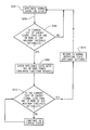
With reference to FIG. 2, a control method in accordance with the present disclosure comprises communicating with an associated utility and receiving and processing the signal indicative of at least one threshold variable (S200), determining a current value in relation to the one threshold variable (S202), operating the appliance in a first operating mode during one period relative to a first comparison between the current value and the threshold variable (S204), operating the appliance in a second operating mode during another period relative to a second comparison between the current value and the threshold variable (S206), selectively adjusting any number of one or more power consuming features/functions of the appliance to adjust power consumption of the appliance in the second operating mode (S206), and returning to the first operating mode (S210) after the threshold variable is over (S212). The selective adjustment can include adjusting power in the second operating mode, for example, selecting one or more of the operational adjustments described above.
It is to be appreciated that appliances can be delayed in their operation, rescheduled for a later start time, and/or altered in their functioning/features in order to reduce energy demands. Some appliances lend themselves to an altered operation due to their functionality. For example, dishwashers, clothes washers, and clothes dryers all have the capacity to run as needed because demand on these appliances is either not constant and/or the functions of these appliances are such that immediate response is not necessary. As one illustrative example, a dishwasher that has been loaded during the daytime, i.e., on-peak demand period hours, can be programmed to start its operations for a later, albeit off-peak demand hours. It is to be appreciated that on-peak and off-peak demand hours can correspond to high utility costs and relatively low utility costs ($/kilowatt), respectively.
The operation of the appliance may vary as a function of a characteristic of the supplied energy, e.g., availability and/or price. Because some energy suppliers offer what is known as time-of-use pricing in their tariffs, price points could be tied directly to the tariff structure for the energy supplier. If real time pricing is offered by the energy supplier serving the site, this variance could be utilized to generate savings and reduce chain demand. Another load management program offered by energy supplier utilizes price tiers which the utility manages dynamically to reflect the total cost of energy delivery to its customers. These tiers provide the customer a relative indicator of the price of energy and are usually defined as being LOW (level 1), MEDIUM (level 2), HIGH (level 3), and CRITICAL (level 4). The operational and functional adjustments described above, and others, can be initiated and/or dependent upon the tiers, i.e. threshold variables. For example, a dishwasher sanitize cycle, and/or other functions, can be prevented or ‘blocked’ from activating if the pricing tier is at level 3 or 4
The use of the module translator board (FIG. 3) 300 in between the appliance and a utility, wireless energy device, communication network 304, HEM 100, etc. to handle all wireless protocol information (including proprietary wireless on 802.15.4, Zigbee, and Smart Energy Profile information) reduces the demand on microprocessor/microcontroller memory usage on the appliances 302 (including dishwashers, refrigerators, oven ranges, clothes washing machines, clothes dryers, microwave ovens, water heaters, and room air conditioners). The translator board 300 can provide the ability (via card slot, connector connection, etc.) to interact with a variety of different radio or wireless cards including: Zigbee, Proprietary 802.15.4, FM radio, and WiFi. The translator board 300 can also act as a translator for protocol profiles e.g. Smart Energy Profile or any Home Automation profile. These profiles require a lot of software overhead so the translator board 300 will translate these profiles into a simple current energy level to each appliance.
Zigbee Smart Energy Profile data events can be given a time an event starts and a time an event ends. The translator board 300 can create a calendar of events with each of these Smart Energy Profile messages. For example, a Smart Energy Profile event with a start time and an end time will be converted to a calendar event and at the time the event is supposed to begin the calendar will send the appropriate event with all of the appropriate data included in this event. The calendar can store many events and one important feature if you use an event calendar technique is that you can remove any event at any time with an appropriate event ID. Smart Energy profile commands contain “Cancel Event” messages if an event that was previously sent out needs to be canceled. Event calendars do not hold events in any order so any events can be removed from the calendar at any time.
The translator board 300 can use MOBDUS or MODBUS ASCII to communicate to appropriate radios or wireless modules 306. The translator board 300 will also have the capability to communicate via Spi, I2C, RS232 Uart, or LVTTL (or TTL) full duplex serial to any radio or wireless module that will be connected to it. If the translator board 300 loses connectivity to the wireless host or server for a designated amount of time, then the translator can communicate the lowest energy level, or other pre-selected energy level, to all appliances in order for the appliances to function in full operation without needing to remove the translator board. There can be a “test” mode on the translator board that can be entered via button press, user interface sequence, or any kind of serial or wireless communication that will allow the module to scroll through each energy level rate and observe the reaction or response on the appliance. The idea of this mode is to enable an easy means of testing appliance response without needing to wait for utility or energy manager server energy level updates.
The use of the translator board 300 reduces the problem of increasing microcontroller ROM/RAM/EEPROM size by the incorporation of wireless/energy management technologies onto each appliance control 302. The smart energy profile data can be sent as event start and stop time commands. All of these commands can be accumulated into a calendar of events wherein the events are in no particular order but can contain their event ID, the time/date the event needs to occur, data in the event, and an event name. With this calendar method, many events can be stored. Since the events are stored in memory in no particular order, any event can be removed at any time. Once an event occurs it is automatically removed from the calendar.
The translator board can contain a “card” connection or “circuit board” connection via a board to board connection interface for all radio or wireless technologies. This provides for a way to accommodate many radio or wireless technologies with the same translator board. When the “card” or “circuit board” is connected the translator board can detect what interface/protocol the card is using and map the internal software accordingly. There can be one common connection from the translator board to all of the respective appliances in order to enable a single translator board to function with all of the appliances.
The disclosure has been described with reference to the preferred embodiments. Obviously, modifications and alterations will occur to others upon reading and understanding the preceding detailed description. It is intended that the disclosure be construed as including all such modifications and alterations.

Claims (7)

What is claimed is:
1. A home energy management system comprising:
at least one appliance including one or more power consuming functions connected with the home energy management system (HEM);
an energy profile comprising at least one calendared energy event;
a controller configured to receive and process a demand response signal from an associated utility, the demand response signal indicative of a current energy cost level associated with a current energy cost data supplied by the associated utility;
a translator board for wireless communication of the current energy cost level and/or a calendared energy event of the at least one calendared energy event from the HEM to the at least one appliance;
wherein (i) the controller effects a load controlling scheme of at least one of the at least one appliance, wherein the at least one of the at least one appliance operates in a full operating mode when the current energy cost level is at or below a predetermined threshold level and/or before or after the calendared energy event, and in a second operating mode when the energy cost level is above the threshold value and/or during the calendared energy event, (ii) in the second operating mode, the at least one of the at least one appliance skips at least one of the power consuming functions from a cycle of functions to shed a load, and (iii) in an event the translator board loses connectivity with an associated wireless host or server, the translator board is configured to automatically communicate a signal to enable the at least one of the at least one appliance to function in the full operating mode without requiring a removal of the translator board.
2. The home energy management system according to claim 1, wherein the translator board includes duplex serial capability.
3. The home energy management system according to claim 1, wherein the at least one appliance includes a default control which enables functions in the full operating mode in an event any communication between the HEM and the at least one appliance is compromised.
4. A method of managing energy comprising:
profiling at least one appliance including one or more power consuming functions connected with a home energy management system (HEM);
defining an energy event corresponding to each of the one or more power consuming functions;
developing a home energy profile in the HEM of all the energy events including a calendar of energy events;
receiving and processing via a controller a demand response signal indicative of at least one of the calendared energy events; and
wirelessly communicating the at least one calendared energy event via a translator board from the HEM to at least one of the at least one appliance;
wherein (i) effecting, via the controller, a load controlling scheme of the at least one of the at least one appliance, wherein the at least one of the at least one appliance operates in a full operating mode before and after the at least one calendared energy event and in a second operating mode during the at least one calendared energy event, (ii) in the second operating mode, skipping at least one of the power consuming functions from a cycle of functions of the at least one of the at least one appliance and shedding a load, and (iii) in an event the translator board loses connectivity with an associated wireless host or server, automatically communicating a signal via the translator board to the at least one of the at least one appliance so that the at least one of the at least one appliance is able to function in the full operating mode without requiring a removal of the translator board.
5. The method of managing energy according to claim 4, wherein the translator board includes duplex serial capability.
6. The method of managing energy according to claim 4, wherein each energy event includes information selected from the group consisting of event ID, date of event, time of event, duration of event, functional data of event, energy consumption of event, and event name.
7. The method of managing energy according to claim 4, wherein the at least one appliance includes a default control which functions in the full operating mode in an event any communication between the HEM and the at least one appliance is compromised.
US12/644,509 2009-12-22 2009-12-22 Demand response appliance module Active 2030-10-16 US8417393B2 (en)

Priority Applications (1)

Application Number Priority Date Filing Date Title
US12/644,509 US8417393B2 (en) 2009-12-22 2009-12-22 Demand response appliance module

Applications Claiming Priority (1)

Application Number Priority Date Filing Date Title
US12/644,509 US8417393B2 (en) 2009-12-22 2009-12-22 Demand response appliance module

Publications (2)

Publication Number Publication Date
US20110153109A1 US20110153109A1 (en) 2011-06-23
US8417393B2 true US8417393B2 (en) 2013-04-09

Family

ID=44152234

Family Applications (1)

Application Number Title Priority Date Filing Date
US12/644,509 Active 2030-10-16 US8417393B2 (en) 2009-12-22 2009-12-22 Demand response appliance module

Country Status (1)

Country Link
US (1) US8417393B2 (en)

Cited By (7)

* Cited by examiner, † Cited by third party
Publication number Priority date Publication date Assignee Title
US20120101652A1 (en) * 2010-10-25 2012-04-26 Samsung Electronics Co., Ltd. Power management apparatus, power management system including the power management apparatus, and method for controlling the power management system
US20120197455A1 (en) * 2011-01-31 2012-08-02 Samsung Electronics Co., Ltd. Method and apparatus for managing power of smart appliance
US20170116688A1 (en) * 2010-06-26 2017-04-27 Lg Electronics Inc. Network system
US20170148039A1 (en) * 2014-05-23 2017-05-25 Singapore University Of Technology And Design Power monitoring apparatus, a method for power monitoring and a base station used with the aforementioned
US9819261B2 (en) 2012-10-25 2017-11-14 Semiconductor Energy Laboratory Co., Ltd. Central control system
US9979337B2 (en) 2014-04-24 2018-05-22 Generac Power Systems, Inc. Method of loadshedding for a variable speed, constant frequency generator
US10069331B2 (en) 2015-01-09 2018-09-04 Generac Power Systems, Inc. Load shed module

Families Citing this family (19)

* Cited by examiner, † Cited by third party
Publication number Priority date Publication date Assignee Title
US8239073B2 (en) * 2008-04-17 2012-08-07 Asoka Usa Corporation Systems and methods for controlling energy consumption
US8996184B2 (en) * 2010-05-13 2015-03-31 Lsis Co., Ltd. Apparatus and method for energy management
US9146604B2 (en) * 2010-12-16 2015-09-29 Lg Electronics Inc. Power control apparatus and power control method
US20120065798A1 (en) * 2010-12-29 2012-03-15 General Electric Company Demand response of devices when different devices are being signaled to shed load
US8947245B2 (en) 2011-08-30 2015-02-03 General Electric Company Apparatus and method for transmitting operating cycle alerts
US9209624B2 (en) 2011-11-03 2015-12-08 General Electric Company System and method for overriding demand system management enabled functions
WO2013080984A1 (en) * 2011-11-28 2013-06-06 京セラ株式会社 Power control device, power control system, and power control method
DE102011087277A1 (en) 2011-11-29 2013-05-29 BSH Bosch und Siemens Hausgeräte GmbH Energy management system for household appliances with a communication bridge by means of a power grid as required, as well as the associated process
DE102011087278A1 (en) 2011-11-29 2013-05-29 BSH Bosch und Siemens Hausgeräte GmbH System for home appliance energy management taking into account an evolutionary mobile radio standard and associated method
DE102011089105A1 (en) 2011-12-20 2013-06-20 BSH Bosch und Siemens Hausgeräte GmbH Radio module for a domestic appliance with adaptable radio standard and associated domestic appliance
KR20130091845A (en) * 2012-02-09 2013-08-20 한국전자통신연구원 Apparatus and method for control smart appliance using smart terminal
US9010133B2 (en) 2012-06-20 2015-04-21 Whirlpool Corporation On-line energy consumption optimization adaptive to environmental condition
US20140025219A1 (en) * 2012-07-18 2014-01-23 Jay Andrew Broniak Home energy management system with sabbath compliant functionality
US9375125B2 (en) 2012-12-20 2016-06-28 Whirlpool Corporation Household appliance having antennas
US9541421B2 (en) * 2013-10-03 2017-01-10 Landis+Gyr Innovations, Inc. In-premises management of home area networks
US9924849B2 (en) 2014-10-07 2018-03-27 Whirlpool Corporation Dishwasher with integrated closure element having an antenna
US10152074B2 (en) * 2015-06-09 2018-12-11 Honeywell International Inc. Energy management using a wearable device
DE102016210885A1 (en) * 2016-06-17 2017-12-21 Siemens Aktiengesellschaft A method for controlling an energy flow in a multiple network energy network
US10479166B2 (en) * 2017-12-29 2019-11-19 Denso International America, Inc. Toggle button

Citations (9)

* Cited by examiner, † Cited by third party
Publication number Priority date Publication date Assignee Title
US4847781A (en) * 1986-09-23 1989-07-11 Associated Data Consoltants Energy management system
US20030233201A1 (en) * 2002-06-13 2003-12-18 Horst Gale Richard Total home energy management
US20040224630A1 (en) * 2003-05-05 2004-11-11 Macfarland Darin Wireless communications system - tractor / trailer
US20060036350A1 (en) * 1994-10-25 2006-02-16 Bohrer Philip J Profile based method for deriving a temperature setpoint using a 'delta' based on cross-indexing a received price-point level signal
US7010363B2 (en) 2003-06-13 2006-03-07 Battelle Memorial Institute Electrical appliance energy consumption control methods and electrical energy consumption systems
US7079967B2 (en) 2001-05-11 2006-07-18 Field Diagnostic Services, Inc. Apparatus and method for detecting faults and providing diagnostics in vapor compression cycle equipment
US20070021874A1 (en) * 2005-07-22 2007-01-25 Roger Rognli Load shedding control for cycled or variable load appliances
US20080315000A1 (en) 2007-06-21 2008-12-25 Ravi Gorthala Integrated Controller And Fault Indicator For Heating And Cooling Systems
US8073573B2 (en) * 2003-06-13 2011-12-06 Battelle Memorial Institute Electrical power distribution control methods, electrical energy demand monitoring methods, and power management devices

Patent Citations (9)

* Cited by examiner, † Cited by third party
Publication number Priority date Publication date Assignee Title
US4847781A (en) * 1986-09-23 1989-07-11 Associated Data Consoltants Energy management system
US20060036350A1 (en) * 1994-10-25 2006-02-16 Bohrer Philip J Profile based method for deriving a temperature setpoint using a 'delta' based on cross-indexing a received price-point level signal
US7079967B2 (en) 2001-05-11 2006-07-18 Field Diagnostic Services, Inc. Apparatus and method for detecting faults and providing diagnostics in vapor compression cycle equipment
US20030233201A1 (en) * 2002-06-13 2003-12-18 Horst Gale Richard Total home energy management
US20040224630A1 (en) * 2003-05-05 2004-11-11 Macfarland Darin Wireless communications system - tractor / trailer
US7010363B2 (en) 2003-06-13 2006-03-07 Battelle Memorial Institute Electrical appliance energy consumption control methods and electrical energy consumption systems
US8073573B2 (en) * 2003-06-13 2011-12-06 Battelle Memorial Institute Electrical power distribution control methods, electrical energy demand monitoring methods, and power management devices
US20070021874A1 (en) * 2005-07-22 2007-01-25 Roger Rognli Load shedding control for cycled or variable load appliances
US20080315000A1 (en) 2007-06-21 2008-12-25 Ravi Gorthala Integrated Controller And Fault Indicator For Heating And Cooling Systems

Cited By (14)

* Cited by examiner, † Cited by third party
Publication number Priority date Publication date Assignee Title
US20170116688A1 (en) * 2010-06-26 2017-04-27 Lg Electronics Inc. Network system
US10296989B2 (en) * 2010-06-26 2019-05-21 Lg Electronics Inc. Network system
US8918224B2 (en) * 2010-10-25 2014-12-23 Samsung Electronics Co., Ltd. Power management apparatus, power management system including the power management apparatus, and method for controlling the power management system
US20120101652A1 (en) * 2010-10-25 2012-04-26 Samsung Electronics Co., Ltd. Power management apparatus, power management system including the power management apparatus, and method for controlling the power management system
US9564755B2 (en) * 2011-01-31 2017-02-07 Samsung Electronics Co., Ltd Method and apparatus for managing power of smart appliance
US20120197455A1 (en) * 2011-01-31 2012-08-02 Samsung Electronics Co., Ltd. Method and apparatus for managing power of smart appliance
US9819261B2 (en) 2012-10-25 2017-11-14 Semiconductor Energy Laboratory Co., Ltd. Central control system
US10630176B2 (en) 2012-10-25 2020-04-21 Semiconductor Energy Laboratory Co., Ltd. Central control system
US9979337B2 (en) 2014-04-24 2018-05-22 Generac Power Systems, Inc. Method of loadshedding for a variable speed, constant frequency generator
US20170148039A1 (en) * 2014-05-23 2017-05-25 Singapore University Of Technology And Design Power monitoring apparatus, a method for power monitoring and a base station used with the aforementioned
US10069331B2 (en) 2015-01-09 2018-09-04 Generac Power Systems, Inc. Load shed module
US10554074B2 (en) 2015-01-09 2020-02-04 Generac Power Systems, Inc. Load shed system
US11108265B2 (en) 2015-01-09 2021-08-31 Generac Power Systems, Inc. Load shed system
US11831197B2 (en) 2015-01-09 2023-11-28 Generac Power Systems, Inc. Load shed system

Also Published As

Publication number Publication date
US20110153109A1 (en) 2011-06-23

Similar Documents

Publication Publication Date Title
US8417393B2 (en) Demand response appliance module
US8369998B2 (en) Updating demand response settings
US9058037B2 (en) Return of appliance state after demand response event
US8355826B2 (en) Demand side management module
AU2011203530B2 (en) Appliance incorporating load selectivity without employment of smart meters
US20110153101A1 (en) Household energy management system and method for one or more appliances
CN102377182A (en) Load shed system for demand response without AMI/AMR system

Legal Events

Date Code Title Description
AS Assignment

Owner name: GENERAL ELECTRIC COMPANY, NEW YORK

Free format text: ASSIGNMENT OF ASSIGNORS INTEREST;ASSIGNORS:DRAKE, JEFF DONALD;FINCH, MICHAEL F.;BESORE, JOHN K.;AND OTHERS;REEL/FRAME:023688/0801

Effective date: 20091216

STCF Information on status: patent grant

Free format text: PATENTED CASE

FPAY Fee payment

Year of fee payment: 4

AS Assignment

Owner name: HAIER US APPLIANCE SOLUTIONS, INC., DELAWARE

Free format text: ASSIGNMENT OF ASSIGNORS INTEREST;ASSIGNOR:GENERAL ELECTRIC COMPANY;REEL/FRAME:038966/0459

Effective date: 20160606

MAFP Maintenance fee payment

Free format text: PAYMENT OF MAINTENANCE FEE, 8TH YEAR, LARGE ENTITY (ORIGINAL EVENT CODE: M1552); ENTITY STATUS OF PATENT OWNER: LARGE ENTITY

Year of fee payment: 8