US8424074B2 - Method for deploying a firewall and virtual private network to a computer network - Google Patents
Method for deploying a firewall and virtual private network to a computer network Download PDFInfo
- Publication number
- US8424074B2 US8424074B2 US12/486,133 US48613309A US8424074B2 US 8424074 B2 US8424074 B2 US 8424074B2 US 48613309 A US48613309 A US 48613309A US 8424074 B2 US8424074 B2 US 8424074B2
- Authority
- US
- United States
- Prior art keywords
- firewall
- vst
- computer network
- internet
- client
- Prior art date
- Legal status (The legal status is an assumption and is not a legal conclusion. Google has not performed a legal analysis and makes no representation as to the accuracy of the status listed.)
- Expired - Fee Related, expires
Links
Images


Classifications
-
- H—ELECTRICITY
- H04—ELECTRIC COMMUNICATION TECHNIQUE
- H04L—TRANSMISSION OF DIGITAL INFORMATION, e.g. TELEGRAPHIC COMMUNICATION
- H04L63/00—Network architectures or network communication protocols for network security
- H04L63/02—Network architectures or network communication protocols for network security for separating internal from external traffic, e.g. firewalls
- H04L63/0209—Architectural arrangements, e.g. perimeter networks or demilitarized zones
-
- H—ELECTRICITY
- H04—ELECTRIC COMMUNICATION TECHNIQUE
- H04L—TRANSMISSION OF DIGITAL INFORMATION, e.g. TELEGRAPHIC COMMUNICATION
- H04L63/00—Network architectures or network communication protocols for network security
- H04L63/02—Network architectures or network communication protocols for network security for separating internal from external traffic, e.g. firewalls
- H04L63/0272—Virtual private networks
-
- H—ELECTRICITY
- H04—ELECTRIC COMMUNICATION TECHNIQUE
- H04L—TRANSMISSION OF DIGITAL INFORMATION, e.g. TELEGRAPHIC COMMUNICATION
- H04L63/00—Network architectures or network communication protocols for network security
- H04L63/20—Network architectures or network communication protocols for network security for managing network security; network security policies in general
Definitions
- This invention relates to the security of local networks; for example, in business establishments. Unauthorized access often results in theft of critical data, such as credit card information, personal identification information, business proprietary information and the like.
- critical data such as credit card information, personal identification information, business proprietary information and the like.
- the present invention is a method and system for remotely securing a network from unauthorized access, and simultaneously creating a virtual private network (VPN) structure, with minimal human intervention at the business establishment allowing for a highly secure, highly scalable solution.
- VPN virtual private network
- IP Internet Protocol
- This process can take significantly more time to perform a firewall installation than the present invention requires, and it may be necessary to shut down the site for an extended period of time, wait for a lull in the site's transaction processing, or possibly require skilled technical personnel to perform the installation overnight.
- firewalls used for security purposes are typically shipped at least twice; first, from the manufacturer to the vendor for customization and, second, from the vendor to the site for installation. If customization errors occur, in addition to rendering the local network inoperative, the firewall may need to be shipped a third time, back to the vendor for correction, and then a fourth time, back to the site for another installation attempt.
- the present invention addresses all the above-mentioned drawbacks in the prior art.
- the present invention enables the installation of a network security system without the need for on-site visits by technicians and can be implemented remotely.
- several unique techniques have been developed as will be apparent in the following detailed description of the invention. Briefly, in order to achieve remote installation, the following hurdles needed to be overcome. First, it would not be feasible to have employees at the business site renumber the Internet Protocol (IP) addresses of all the local devices on the network. Second, in the event of an installation error, the site must be capable of being restored to its pre-installation state to permit the business to continue to operate while the installation problems are diagnosed and solved. Third, remote access to the firewall may not be possible from the public Internet.
- IP Internet Protocol
- An object of this invention is to secure a local network in a manner that does not require the IP addresses of any devices on the local network (e.g., router, workstations, servers) to be renumbered.
- Another object of the invention is to have the system automatically revert to its previous code by programming the firewall from the protected local area network (LAN) side, not the unprotected Internet side, if an error occurs.
- LAN local area network
- Further objects of the invention include securing a remote network by utilizing a person with minimal technical skill to install, and, if necessary, uninstall the solution and to minimize shipping costs by allowing the hardware device to be shipped directly from a distributor.
- a further object of the invention is to establish a VPN for multiple related local networks where the established VPN allows devices at different sites to have the same IP address.
- a further object of the invention is to allow for the site to be restored to its pre-installation state if hardware installation fails.
- An additional object of the invention is to secure a local network in a manner that does not require public static IP addresses to the Internet in order to manage the solution.
- FIG. 1 illustrates a typical business network.
- FIG. 2 illustrates the network of FIG. 1 with a typical firewall installation.
- FIG. 3 illustrates the network of FIG. 1 with the firewall configured in route-mode according to the invention.
- FIG. 4 is a diagram of the network address translation (NAT) functions. This aspect of the invention allows the local IP addresses to remain unchanged.
- NAT network address translation
- FIG. 5 is a flowchart of the VST Client command processing sequence.
- the interaction of VST Tracking, SQL Database, VST Client Web Service and the VST Client allows for remote management and configuration of the site's local network.
- FIG. 6 is a flowchart of Step 1 of the VST Firewall installation process: Installation of the VST Client software.
- FIG. 7 is a flowchart of Step 2 of the VST Firewall installation process: LAN Scan.
- FIG. 8 is a flowchart of Step 3 of the VST Firewall installation process: Physical installation of the firewall.
- FIG. 9 is a flowchart of Step 4 of the VST Firewall installation process: Firewall logs activities.
- FIG. 10 is a flowchart of Step 5 of the VST Firewall installation process: retrieve firewall logs.
- FIG. 11 is a flowchart of Step 6 of the VST Firewall installation process: Create the firewall configuration.
- FIG. 12 is a flowchart of Step 7 of the VST Firewall installation process: Configure the firewall to route-mode.
- FIG. 13 is a flowchart of optional Step 8 of the VST Firewall installation process: Remove router. This process further illustrates the present invention's ability to remotely manage and modify the site's configuration with minimal downtime and without onsite technical expertise.
- FIG. 14 is a flowchart illustrating the setup and enforcement of the Rogue Device Detection and Rogue Device Prevention functionality that protects the network from unauthorized network access from within the site without the expense of additional hardware support.
- FIG. 15 illustrates the network of FIG. 1 with the firewall configured in bridge-mode according to the invention.
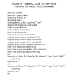
- FIG. 16 provides an example of firewall code that places the firewall into a bridge configuration.
- a typical business network would include a plurality of workstations 10 and at least one server 11 .
- the business may be a restaurant that includes a plurality of workstations that waitpersons use to record food orders and settle checks by appropriate charges to credit card accounts.
- the transactions are stored on a server 11 and are settled in batches over the Internet 15 at any convenient time.
- the workstations 10 and server(s) 11 are connected to a switch 12 which in turn is connected to a router 13 .
- the router is connected to the Internet 15 via a modem 14 .
- the functions of switch 12 , router 13 , and modem 14 may be provided by one or more physical devices.
- the prior art approach as shown in FIG. 2 is to replace the router with a firewall and have technicians visit the site to ascertain all the required information about the network, including the number and type of network-connected devices, their IP addresses, etc., and then make the necessary programming changes and settings for the firewall. This process has all of the disadvantages of the prior art mentioned above.
- a known firewall 17 as indicated in FIG. 15 (e.g. model SSG-5-SB-M manufactured by Juniper) is sent to the restaurant, for example, with instructions on how to connect it to the network. This requires minimal computer skills.
- the Juniper is put inline with the network traffic. If the site has an existing router, a non-technical person at the site disconnects a network device from the existing router, and the Juniper 0/0 port is connected to that port on the site's router ( FIG. 8 , 306 - 307 ). If the site's network does not have a router, the Juniper's 0/0 port is connected to the Ethernet/LAN port on the site's Internet connection device ( FIG. 8 , 308 ).
- the site's network devices are then connected to the Juniper's open ports, 0/2-0/6, or to a switch that is connected to one of those ports ( FIG. 8 , 309 ).
- the person performing the installation then powers on the firewall ( FIG. 8 , 310 ).
- This configuration adds the Juniper firewall to the network without disrupting the flow of network traffic.
- the firewall is sent to the site in a bridge-mode configuration that transparently passes data between the firewall interfaces.
- FIG. 16 provides VST code that places the Juniper firewall into a bridge-mode configuration.
- any device that attempts to communicate to the Internet uses its default gateway address which will generally be that of the original router. With the original site deployment of the firewall in bridge-mode, the firewall will not interrupt this flow of network traffic.
- the LAN side of the firewall must take over the role of the default gateway for the local network, and the default gateway for the firewall must be set to the LAN IP address of the router, which is now also the firewall's LAN address. To accomplish this task, the firewall must support virtual routers.
- the Juniper SSG series firewalls have two default virtual routers called “Trust-VR” and “Untrust-VR” indicated as VR1 and VR2, respectively, in FIG. 3 within firewall 19 .
- Route-mode configuration starts by putting the firewall LAN interface into the TRUST-VR. The next step is to set the default gateway of the Trust-VR to the Untrust VR. The firewall WAN interface is then put into the Untrust-VR.
- the firewall WAN interface IP address can be set to any legitimate IP address on the LAN network other than the LAN interface IP address.
- the default gateway for the Untrust-VR is set to the LAN IP address of the site's router. This IP address in the Untrust-VR is also the same as the firewall's LAN interface IP address. Packets from the firewall's LAN interface can now route out of the firewall. Returning packets are properly routed because the firewall has session data which is evaluated before a route lookup and therefore has a path back to the initiating host.
- FIG. 4 illustrates how the VPN communicates so that renumbering the IP addresses at the site is not necessary.
- IP masquerading also known as NAT.
- a backbone network whose IP network is 1.0.0.0/8 is created. Each site is given a network segment in the form of 1.X.Y.0/24 that is unique across the entire VPN.
- Backbone firewalls need to have the corresponding security association information configured to setup a site's VPN.
- the X and Y are created sequentially so that a starting and ending range of X's and Y's belong to a specific backbone firewall.
- not all backbone Juniper firewalls can terminate the same number of security associations.
- VPN growth cost can be tied to the number of security associations that need to be created by mapping X and Y values to a specific backbone firewall.
- backbone firewall 1 For example, 1.4.0.0 to 1.7.255.0 belong to backbone firewall 1 , and 1.8.0.0 to 1.15.255.0 belong to backbone firewall 2 . In this way, when additional security associations are required backbone firewall 3 may be purchased.
- the firewalls use either static routes or dynamic routing protocols to intercommunicate with each other.
- DNS Domain Name System
- the site's firewall performs the NAT translation between the LAN network and the site's backbone addresses.
- a loopback interface is used to hold the NAT table, so that multiple physical interfaces can be set up allowing for multiple fault tolerant paths to the Internet.
- FIG. 4 A detailed example is shown in FIG. 4 .
- firewalls managed by the present invention could potentially have the same subnets on their local networks.
- all three subnets are 192.168.1.0/24. Since site to site communication over the VPN is possible, a NAT system is required. The invention's implementation of NAT allows for this communication without having to renumber the site.
- the process begins by assigning each site a backbone subnet of 1.X.Y.0/24 that is unique on the VPN.
- Each local device that is accessible over the VPN is mapped in a NAT table in that site's local firewall to a 1.X.Y.Z/32 address which is unique to the VPN.
- publicly accessible DNS servers are used to map DNS A-record names to the VPN NAT host addresses.
- the DNS servers are public so that hosts can access the records without changing their local host DNS server settings.
- WRK 1 at store 1 of location mac-001 needs to communicate to WRK 1 at store 2
- WRK 1 at store 1 would first query its public DNS servers to obtain the 1.X.Y.Z/32 address for WRK 1 at store 2 , 1.10.16.2, in this case.
- a data packet then could be sent to that address which would be interpreted by the site's firewall as an address that belongs on the VPN (rather than the Internet). This causes the firewall to translate the source address of WRK 1 at store 1 to 1.10.15.2 and then forward the packet over the VPN to the backbone firewalls.
- the backbone firewalls know how to address all 1.X.Y.0/24 sites via destination table look ups and would forward the packet to the firewall at store 2 .
- the firewall at store 2 When the firewall at store 2 received these packets, it would translate the destination address to the appropriate local address, 192.168.1.10 in this case, and pass the packets to WRK 1 at store 2 .
- WRK 1 at store 2 replies to WRK 1 at store 1 , the process will work in reverse.
- WRK 1 at store 2 will send its response to WRK 1 at store 1 , 1.10.15.2 in this case, which will be interpreted by the firewall at store 2 and sent over the backbone VPN to the firewall at store 1 .
- the firewall at store 1 When the firewall at store 1 receives the packets, it will translate the destination address back to the local address of WRK 1 at store 1 , 192.168.1.10 in this case, and forward the packets.
- This example demonstrates successful communication over the VPN between devices with the same local IP address.
- VST has developed a Windows-based software client that operates on the LAN side of the firewall.
- VST calls this client software the “VST Client.”
- the VST Client implements Rogue Device Detection to provide notification whenever an unauthorized device is detected by the firewall.
- the VST Client implements Rogue Device Prevention to prevent unauthorized devices from passing traffic through the firewall.
- the VST Client keeps a record of all IP address/MAC address pairs which are authorized to access the network. This record, which VST calls the “Reference ARP Table”, is stored in the VST Client's encrypted configuration file. Changes to the Reference ARP Table can be made by VST personnel using the VST Tracking application. These changes are then transmitted to the VST Client via the VST Client Web Service. Using the VST Tracking application, VST personnel can choose to have unauthorized devices prevented from communicating through the firewall (Rogue Device Prevention), or to have the presence of unauthorized devices on the network merely reported (Rogue Device Detection).
- the VST Client configures the firewall ARP table so that only devices with an IP address/MAC address pair in the Reference ARP Table may pass traffic through the firewall. This is done by making all ARP entries on the firewall static. If an IP address/MAC address pair is authorized to access the network, a static entry is made to the firewall ARP table using this IP address/MAC address pair. For all IP addresses which are on the subnet, but not authorized to access the network, a static entry is made to the firewall ARP table using a randomly generated, fictitious MAC address, thus preventing network traffic passing through the firewall from this IP address.
- the VST Client retrieves the current ARP table from the firewall and checks that it matches the Reference ARP Table. If there are devices on the network that are not authorized, the VST Client reports this fact via the VST Client Web Service, which in turn alerts VST personnel.
- VST Tracking is a Microsoft DotNet 3.5 software application developed by VST that provides a User Interface to a SQL Database. Through this interface VST employees can send instructions to the VST Client to support the network at any site. VST Tracking is also used by VST to track security deployments, customer specific data, remote access permissions, firewall inventory, and the associations between resellers, owners, customers and locations (sites).
- the VST Client Web Service is a Microsoft DotNet 3.5 web service developed by VST that provides a method for the VST Client to make use of data in the SQL Database.
- the VST Client Web Service publishes a set of Internet available commands for use by the VST Client.
- the VST Client is a Microsoft DotNet 2.0 software application developed by VST that provides a VST presence on the site's local network. It periodically makes an SSL encrypted call over the public Internet to the VST Client Web Service. If the SQL database contains a command for the VST Client to execute, the command is returned to the VST Client by the VST Client Web Service.
- the commands available in the SQL database are entered by the VST Tracking program through VST personnel's interaction with the VST Tracking user interface. This sequence of events is illustrated in FIG. 5 .
- the process of installing and configuring the present invention involves seven steps.
- An optional step 8 is described in FIG. 13 .
- Step one in the process begins by VST personnel entering initial information about the site into a database through the VST Tracking application ( FIG. 6 , 100 ).
- a person at the site downloads the VST Client application to one of the servers or workstations on the local network.
- the VST Client installer is available on a public web server and the application is installed via the Internet on one of the local workstations or servers ( FIG. 6 , 101 - 103 ).
- There are other known methods of loading the VST Client application on the local network for example, by loading the client application on a hard disk or flash drive and physically sending it to the site for installation.
- the VST Client ID must be registered ( FIG. 6 , 104 - 106 ).
- the VST Client ID is a unique identifier supplied by VST for each instance of the VST Client.
- the VST Client provides a user interface that allows the person at the business to enter the unique VST Client ID and initiate the registration of the VST Client at that site.
- the VST Client is designed to communicate back to the VST network over the Internet for updating itself and receiving command execution instructions.
- Step two prompts the VST Client to conduct a LAN Scan.
- This process is shown in FIG. 7 .
- VST personnel Using the VST Tracking application, VST personnel will request that a LAN Scan be performed by the VST Client at a selected site. This command is stored in a database and transmitted to the VST Client via the VST Client Web Service ( FIG. 7 , 201 - 205 ).
- VST Client When performing a LAN Scan the VST Client gathers the following data and then returns it to the VST Client Web Service which stores the data in a database where it may be accessed by VST personnel via the VST Tracking application ( FIG. 7 , 206 - 214 ):
- VST firewall management server tests and reports if a TCP connection can be made to the address of the VST firewall management server. This address is specified in the command received from the VST Client Web Service ( FIG. 7 , 208 );
- trace route i.e., tracert
- VST Client Web Service All of this information is then sent to the VST Client Web Service to be stored in a database for later analysis by VST personnel ( FIG. 7 , 214 - 215 ).
- Step three is to install the firewall on the site's local network as shown in FIG. 8 .
- a distributor updates the firewall with the current firmware version ( FIG. 8 , 301 ).
- the distributor configures the firewall to bridge-mode using the VST bridge-mode code as previously described ( FIG. 8 , 302 ). All firewalls are shipped with a default configuration that allows the VST Client to access the firewall via IP address 1.0.0.1. Throughout the configuration, this IP address will always be available either as a VLAN interface in bridge-mode, or as a secondary IP address in route-mode.
- the distributor then ships the physical firewall to the site for installation in bridge-mode ( FIG. 8 , 303 ). A non-technical person at the site physically installs the firewall into the existing local network, as previously described ( FIG. 8 , 305 - 310 ).
- step four the firewall gathers information into its logs ( FIG. 9 , 401 ).
- step five through the VST Tracking application, VST personnel request that firewall logs be retrieved by the VST Client at a selected site. This command is stored in a database and transmitted to the VST Client via the VST Client Web Service ( FIG. 10 , 501 - 505 ).
- the VST Client uses a TFTP server to receive the logs from the firewall.
- a TFTP server is built into the VST Client.
- the VST Client employs an algorithm for intelligently selecting the IP address most likely to be accessible to the firewall. In some network topologies, this algorithm will not make the correct choice.
- the VST Tracking application may be used to store a preferred TFTP server address for the VST Client.
- the preferred TFTP server address (if any) is passed to the VST Client by the VST Client Web Service.
- the VST client starts its TFTP server on the appropriate IP address ( FIG. 10 , 507 - 509 ).
- the Windows Firewall is temporarily configured to allow the TFTP transmission of the logs ( FIG. 10 , 510 - 511 ).
- the Windows Firewall is restored to its former status ( FIG. 10 , 519 - 520 ).
- the VST Client then connects to the firewall and instructs it to send the event and traffic logs to the TFTP server ( FIG. 10 , 512 - 514 ).
- the logs are then read by the VST Client and returned to the VST Client Web Service ( FIG. 10 , 515 - 516 ).
- the log files are deleted from the host machine and the TFTP server is stopped ( FIG. 10 , 517 - 518 ).
- the VST Client Web Service then stores the logs in a database where they may be accessed by VST personnel using the VST Tracking application ( FIG. 10 , 521 ).
- step 6 VST personnel will instruct the VST Tracking application to generate a configuration file for a firewall at a selected site from a user-supplied template and configuration data for the location as stored in a database ( FIG. 11 , 601 - 603 ).
- the firewall configuration is then stored in a database ( FIG. 11 , 604 ).
- step 7 using the VST Tracking application, VST personnel will designate a configuration file to be used to program the firewall to route-mode at a selected location ( FIG. 12 , 701 - 702 ).
- the command to configure the firewall is transmitted to the VST Client via the VST Client Web Service ( FIG. 12 , 703 - 705 ).
- the VST Client receives a file to use for programming the firewall it starts the built-in TFTP server ( FIG. 12 , 707 - 709 ), reconfigures the Windows Firewall if needed ( FIG. 12 , 710 - 11 ), logs into the firewall ( FIG. 12 , 712 - 713 ), saves the current firewall configuration ( FIG.
- FIG. 12 , 714 programs the firewall with the new configuration ( FIG. 12 , 715 ) and tests to be sure that the new configuration allows the minimum required connectivity. This includes verifying that the VST Client can ping the firewall ( FIG. 12 , 716 ) and that the VST Client can ping the VST collocation facility through the firewall ( FIG. 12 , 719 ).
- the VST Client will restore the previous firewall configuration ( FIG. 12 , 717 ).
- the VST Client then stops the TFTP server ( FIG. 12 , 720 ), restores the Windows Firewall configuration if needed ( FIG. 12 , 721 - 722 ), and reports the success or failure of the update to the VST Client Web Service ( FIG. 12 , 723 ). This completes the installation process with the firewall configured to route-mode.
- An optional step 8 allows a site that has an existing router to remove the router once the invention is in place. This optional step only applies if the site had an onsite router prior to installation of the invention ( FIG. 13 , 801 ), and there is a desire to remove the router ( FIG. 13 , 803 ).
- VST Tracking application VST personnel generate a new configuration file for the firewall to allow the firewall to take over the Internet gateway functionality handled by the router ( FIG. 13 , 805 ).
- the standard firewall configuration process as described in FIG. 12 , is performed to update the firewall configuration. During this process, between FIG.
- a non-technical person at the site moves the cable from the router's WAN/Internet port to the Juniper 0/0 port ( FIG. 13 , 809 ). If successful, then the process is complete ( FIG. 13 , 810 - 811 ). If the new configuration fails, the VST Client restores the previous firewall configuration ( FIG. 13 , 812 ), a non-technical person at the site moves the cable back to the router's WAN/Internet port ( FIG. 13 , 813 ) and the site is restored to its previous state. VST personnel can then use information gathered from the update failure to diagnose the problem, create a new firewall configuration, and attempt the router removal again ( FIG. 13 , 814 ). All this can be accomplished with minimum downtime for the location and handled without placing technical personnel onsite.
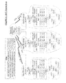
- the flowcharts illustrated in FIG. 14 describe the set up and enforcement of Rogue Device Detection and Rogue Device Prevention, which are part of the invention that further protect the local network once the firewall is installed.
- VST Tracking To enable Rogue Device Detection or Rogue Device Prevention, the VST Tracking user interface is used to indicate whether dynamic or static ARP table control is to be implemented for each firewall interface ( FIG. 14 , 901 - 902 ). Rogue Device Detection is implemented via dynamic ARP table control. Rogue Device Prevention is implemented via static ARP table control. VST Tracking generates firewall configuration data in the firewall's command line interface (CLI) language to clear all static entries for all addresses on all firewall interfaces ( FIG. 14 , 903 ).
- CLI command line interface
- VST Tracking For each firewall interface that is configured for static ARP table control ( FIG. 14 , 904 ), and for each address on such an interface's subnet, VST Tracking determines if the Reference ARP Table held in a database contains the IP address ( FIG. 14 , 907 ). If it does, VST Tracking retrieves the MAC address for the selected IP address from the Reference ARP Table ( FIG. 14 , 909 ). If not, VST Tracking generates a random, fictitious MAC address ( FIG. 14 , 908 ). VST Tracking then uses the MAC address to append additional commands to the firewall configuration data that will create a static ARP table entry for the selected IP address/MAC address pair ( FIG. 14 , 910 ). Once all addresses on each interface's subnet have been handled, VST Tracking writes the Update ARP Table command to a database ( FIG. 14 , 911 ).
- the VST Client When the VST Client receives the Update ARP Table command, it receives the following information with the command: list of all interfaces under dynamic ARP control, list of all interfaces under static ARP control, copy of the Reference ARP Table from a database and the firewall configuration data (i.e., firewall CLI language commands) generated by VST Tracking ( FIG. 14 , 915 ).
- the firewall configuration data i.e., firewall CLI language commands
- the VST Client saves the lists of static and dynamic interfaces to its local encrypted configuration file ( FIG. 14 , 916 - 917 ).
- the VST Client determines whether or not the updates to the firewall ARP table will continue to allow the firewall to communicate with the VST Client's TFTP server ( FIG. 14 , 919 ). If not, the VST Client aborts the command and reports the problem to the VST Client Web Service ( FIG. 14 , 922 ).
- the VST Client saves the ARP table configuration to its encrypted configuration file ( FIG. 14 , 920 ).
- the VST Client uses the configuration data that contains the sequence of firewall CLI commands to update the firewall ARP table via a Merge Configuration command ( FIG. 14 , 921 ). This completes the setup and configuration of the VST Client and the firewall for Rogue Device Detection and Prevention and enables enforcement of Rogue Device Detection and Prevention.
- the VST Client compares the Reference ARP Table with the firewall's current ARP table ( FIG. 14 , 924 ). If there are any IP address/MAC address pairs in the firewall ARP table that are not in the Reference ARP Table ( FIG. 14 , 925 ), then the VST Client sends an alert to VST Tracking via the VST Client Web Service ( FIG. 14 , 926 ).
- the VST Client compares the Reference ARP Table with the firewall's current ARP table ( FIG. 14 , 928 ). If there are any IP address/MAC address pairs in the firewall ARP table that are not in the Reference ARP Table ( FIG. 14 , 929 ), or if there are any IP address/MAC address pairs in the Reference ARP Table that are not in the firewall ARP table as static entries ( FIG. 14 , 930 ), then the VST Client sends an alert to VST Tracking via the VST Client Web Service ( FIG. 14 , 931 ) and attempts to reconfigure the firewall ARP table to match the Reference ARP Table ( FIG. 14 , 932 ).
- the VST Client sends an alert to VST Tracking via the VST Client Web Service ( FIG. 14 , 934 ). In all cases, the VST Client continues to execute its normal polling cycle ( FIG. 14 , 935 ).
Abstract
Description
Claims (5)
Priority Applications (1)
| Application Number | Priority Date | Filing Date | Title |
|---|---|---|---|
| US12/486,133 US8424074B2 (en) | 2009-06-17 | 2009-06-17 | Method for deploying a firewall and virtual private network to a computer network |
Applications Claiming Priority (1)
| Application Number | Priority Date | Filing Date | Title |
|---|---|---|---|
| US12/486,133 US8424074B2 (en) | 2009-06-17 | 2009-06-17 | Method for deploying a firewall and virtual private network to a computer network |
Publications (2)
| Publication Number | Publication Date |
|---|---|
| US20100325730A1 US20100325730A1 (en) | 2010-12-23 |
| US8424074B2 true US8424074B2 (en) | 2013-04-16 |
Family
ID=43355473
Family Applications (1)
| Application Number | Title | Priority Date | Filing Date |
|---|---|---|---|
| US12/486,133 Expired - Fee Related US8424074B2 (en) | 2009-06-17 | 2009-06-17 | Method for deploying a firewall and virtual private network to a computer network |
Country Status (1)
| Country | Link |
|---|---|
| US (1) | US8424074B2 (en) |
Cited By (2)
| Publication number | Priority date | Publication date | Assignee | Title |
|---|---|---|---|---|
| US10623374B2 (en) | 2017-06-09 | 2020-04-14 | Microsoft Technology Licensing, Llc | Automatic network identification for enhanced communications administration |
| US10791064B2 (en) | 2014-12-31 | 2020-09-29 | Samsung Electronics Co., Ltd. | Method and apparatus for allocating server in wireless communication system |
Families Citing this family (6)
| Publication number | Priority date | Publication date | Assignee | Title |
|---|---|---|---|---|
| WO2011027352A1 (en) | 2009-09-03 | 2011-03-10 | Mcafee, Inc. | Network access control |
| US8380863B2 (en) * | 2010-05-05 | 2013-02-19 | Cradle Technologies | Control of security application in a LAN from outside the LAN |
| DE102011076350A1 (en) * | 2011-05-24 | 2012-11-29 | Siemens Aktiengesellschaft | Method and control unit for detecting tampering with a vehicle network |
| KR101599060B1 (en) * | 2014-08-06 | 2016-03-04 | 주식회사 케이티 | Method for determining connection structure of home device, management server and system |
| US10218712B2 (en) * | 2017-01-25 | 2019-02-26 | International Business Machines Corporation | Access control using information on devices and access locations |
| CN110896403A (en) * | 2019-12-31 | 2020-03-20 | 沈阳骏杰卓越软件科技有限公司 | Application firewall architecture |
Citations (5)
| Publication number | Priority date | Publication date | Assignee | Title |
|---|---|---|---|---|
| US6182226B1 (en) | 1998-03-18 | 2001-01-30 | Secure Computing Corporation | System and method for controlling interactions between networks |
| US20020080752A1 (en) * | 2000-12-22 | 2002-06-27 | Fredrik Johansson | Route optimization technique for mobile IP |
| US20060031476A1 (en) * | 2004-08-05 | 2006-02-09 | Mathes Marvin L | Apparatus and method for remotely monitoring a computer network |
| US20100121903A1 (en) * | 2008-11-07 | 2010-05-13 | Sun Microsystems, Inc. | Distributed denial of service deterrence using outbound packet rewriting |
| US20100199345A1 (en) * | 2009-02-04 | 2010-08-05 | Breach Security, Inc. | Method and System for Providing Remote Protection of Web Servers |
-
2009
- 2009-06-17 US US12/486,133 patent/US8424074B2/en not_active Expired - Fee Related
Patent Citations (5)
| Publication number | Priority date | Publication date | Assignee | Title |
|---|---|---|---|---|
| US6182226B1 (en) | 1998-03-18 | 2001-01-30 | Secure Computing Corporation | System and method for controlling interactions between networks |
| US20020080752A1 (en) * | 2000-12-22 | 2002-06-27 | Fredrik Johansson | Route optimization technique for mobile IP |
| US20060031476A1 (en) * | 2004-08-05 | 2006-02-09 | Mathes Marvin L | Apparatus and method for remotely monitoring a computer network |
| US20100121903A1 (en) * | 2008-11-07 | 2010-05-13 | Sun Microsystems, Inc. | Distributed denial of service deterrence using outbound packet rewriting |
| US20100199345A1 (en) * | 2009-02-04 | 2010-08-05 | Breach Security, Inc. | Method and System for Providing Remote Protection of Web Servers |
Non-Patent Citations (1)
| Title |
|---|
| Juniper Networks Integrated Firewall/VPN Platforms, Juniper Networks-Product Category Brochure, pp. 1-8, May 2009. |
Cited By (3)
| Publication number | Priority date | Publication date | Assignee | Title |
|---|---|---|---|---|
| US10791064B2 (en) | 2014-12-31 | 2020-09-29 | Samsung Electronics Co., Ltd. | Method and apparatus for allocating server in wireless communication system |
| US11533275B2 (en) | 2014-12-31 | 2022-12-20 | Samsung Electronics Co., Ltd. | Method and apparatus for allocating server in wireless communication system |
| US10623374B2 (en) | 2017-06-09 | 2020-04-14 | Microsoft Technology Licensing, Llc | Automatic network identification for enhanced communications administration |
Also Published As
| Publication number | Publication date |
|---|---|
| US20100325730A1 (en) | 2010-12-23 |
Similar Documents
| Publication | Publication Date | Title |
|---|---|---|
| US8424074B2 (en) | Method for deploying a firewall and virtual private network to a computer network | |
| CA2555567C (en) | Automated provisioning of phones in packet voice networks | |
| US6816897B2 (en) | Console mapping tool for automated deployment and management of network devices | |
| US11171914B2 (en) | Systems and methods for automatic inventory and DNS record generation | |
| US7539769B2 (en) | Automated deployment and management of network devices | |
| US9461969B2 (en) | Migration of complex applications within a hybrid cloud environment | |
| US8825816B2 (en) | Various methods and apparatuses for a central management station for automatic distribution of configuration information to remote devices | |
| US8214451B2 (en) | Network service version management | |
| US8131850B2 (en) | Apparatus and methods for managing network resources | |
| US20060031476A1 (en) | Apparatus and method for remotely monitoring a computer network | |
| US20020194497A1 (en) | Firewall configuration tool for automated deployment and management of network devices | |
| JP2003032277A (en) | Management method and system of network equipment | |
| EP1639781B1 (en) | Security checking program for communication between networks | |
| US8799466B2 (en) | Method and apparatus for automatic verification of a network access control construct for a network switch | |
| US20020161888A1 (en) | Template-based system for automated deployment and management of network devices | |
| US8359377B2 (en) | Interface for automated deployment and management of network devices | |
| FR2801754A1 (en) | Double IP address assignment procedure uses configuration file allows resource control across networks of LANs. | |
| GB2523123A (en) | Method and hardware device for remotely connecting to and controlling a private branch exchange | |
| Cisco | Configuring Sensor Nodes | |
| WO2023015311A1 (en) | Multiplexing tenant tunnels in software-as-a-service deployments | |
| Headquarters | Cisco Intercompany Media Engine Installation and Configuration Guide | |
| Linder | Network monitoring of automated harbor terminals: Nätverksövervakning av automatiserade hamnterminaler | |
| Headquarters | Cisco Unified Communications Manager Administration Guide, Release 10.0 (1) |
Legal Events
| Date | Code | Title | Description |
|---|---|---|---|
| AS | Assignment |
Owner name: VENDOR SAFE TECHNOLOGIES, TEXAS Free format text: ASSIGNMENT OF ASSIGNORS INTEREST;ASSIGNORS:CYPRUS, MARK E., MR.;FERRILL, JAY R., MR.;REEL/FRAME:022839/0458 Effective date: 20090617 |
|
| STCF | Information on status: patent grant |
Free format text: PATENTED CASE |
|
| AS | Assignment |
Owner name: VENDOR SAFE TECHNOLOGIES, LLC, TEXAS Free format text: CONVERSION OF TX ENTITY TO DE ENTITY;ASSIGNOR:VENDOR SAFE TECHNOLOGIES, LLC;REEL/FRAME:036449/0477 Effective date: 20141110 Owner name: NETSURION LLC, TEXAS Free format text: CHANGE OF NAME;ASSIGNOR:VENDOR SAFE TECHNOLOGIES, LLC;REEL/FRAME:036449/0521 Effective date: 20150228 |
|
| AS | Assignment |
Owner name: SILICON VALLEY BANK, MASSACHUSETTS Free format text: SECURITY AGREEMENT;ASSIGNOR:NETSURION LLC;REEL/FRAME:036539/0442 Effective date: 20150903 |
|
| REMI | Maintenance fee reminder mailed | ||
| FPAY | Fee payment |
Year of fee payment: 4 |
|
| SULP | Surcharge for late payment | ||
| AS | Assignment |
Owner name: SILICON VALLEY BANK, AS ADMINISTRATIVE AGENT, CALI Free format text: PATENT SECURITY AGREEMENT;ASSIGNOR:NETSURION LLC;REEL/FRAME:048877/0746 Effective date: 20190412 |
|
| FEPP | Fee payment procedure |
Free format text: MAINTENANCE FEE REMINDER MAILED (ORIGINAL EVENT CODE: REM.); ENTITY STATUS OF PATENT OWNER: SMALL ENTITY |
|
| LAPS | Lapse for failure to pay maintenance fees |
Free format text: PATENT EXPIRED FOR FAILURE TO PAY MAINTENANCE FEES (ORIGINAL EVENT CODE: EXP.); ENTITY STATUS OF PATENT OWNER: SMALL ENTITY |
|
| STCH | Information on status: patent discontinuation |
Free format text: PATENT EXPIRED DUE TO NONPAYMENT OF MAINTENANCE FEES UNDER 37 CFR 1.362 |
|
| FP | Lapsed due to failure to pay maintenance fee |
Effective date: 20210416 |
|
| AS | Assignment |
Owner name: NETSURION LLC, FLORIDA Free format text: TERMINATION AND RELEASE OF INTELLECTUAL PROPERTY SECURITY AGREEMENT;ASSIGNOR:SILICON VALLEY BANK;REEL/FRAME:060248/0091 Effective date: 20220601 Owner name: NETSURION LLC, FLORIDA Free format text: TERMINATION AND RELEASE OF PATENT SECURITY AGREEMENT;ASSIGNOR:SILICON VALLEY BANK, AS ADMINISTRATIVE AGENT;REEL/FRAME:060248/0087 Effective date: 20220601 |