US8424777B2 - Reducing agent heating system - Google Patents

Reducing agent heating system Download PDF

Info

Publication number
US8424777B2
US8424777B2 US12/070,498 US7049808A US8424777B2 US 8424777 B2 US8424777 B2 US 8424777B2 US 7049808 A US7049808 A US 7049808A US 8424777 B2 US8424777 B2 US 8424777B2
Authority
US
United States
Prior art keywords
reducing agent
engine coolant
engine
heating
heating component
Prior art date
Legal status (The legal status is an assumption and is not a legal conclusion. Google has not performed a legal analysis and makes no representation as to the accuracy of the status listed.)
Active, expires
Application number
US12/070,498
Other versions
US20090205320A1 (en
Inventor
Mahesh K. Mokire
Rishabh Sinha
Current Assignee (The listed assignees may be inaccurate. Google has not performed a legal analysis and makes no representation or warranty as to the accuracy of the list.)
Caterpillar Inc
Original Assignee
Caterpillar Inc
Priority date (The priority date is an assumption and is not a legal conclusion. Google has not performed a legal analysis and makes no representation as to the accuracy of the date listed.)
Filing date
Publication date
Application filed by Caterpillar Inc filed Critical Caterpillar Inc
Priority to US12/070,498 priority Critical patent/US8424777B2/en
Assigned to CATERPILLAR INC. reassignment CATERPILLAR INC. ASSIGNMENT OF ASSIGNORS INTEREST (SEE DOCUMENT FOR DETAILS). Assignors: SINHA, RISHABH, MOKIRE, MAHESH K.
Publication of US20090205320A1 publication Critical patent/US20090205320A1/en
Application granted granted Critical
Publication of US8424777B2 publication Critical patent/US8424777B2/en
Active legal-status Critical Current
Adjusted expiration legal-status Critical

Links

Images

Classifications

    • FMECHANICAL ENGINEERING; LIGHTING; HEATING; WEAPONS; BLASTING
    • F01MACHINES OR ENGINES IN GENERAL; ENGINE PLANTS IN GENERAL; STEAM ENGINES
    • F01NGAS-FLOW SILENCERS OR EXHAUST APPARATUS FOR MACHINES OR ENGINES IN GENERAL; GAS-FLOW SILENCERS OR EXHAUST APPARATUS FOR INTERNAL COMBUSTION ENGINES
    • F01N3/00Exhaust or silencing apparatus having means for purifying, rendering innocuous, or otherwise treating exhaust
    • F01N3/08Exhaust or silencing apparatus having means for purifying, rendering innocuous, or otherwise treating exhaust for rendering innocuous
    • F01N3/10Exhaust or silencing apparatus having means for purifying, rendering innocuous, or otherwise treating exhaust for rendering innocuous by thermal or catalytic conversion of noxious components of exhaust
    • F01N3/18Exhaust or silencing apparatus having means for purifying, rendering innocuous, or otherwise treating exhaust for rendering innocuous by thermal or catalytic conversion of noxious components of exhaust characterised by methods of operation; Control
    • F01N3/20Exhaust or silencing apparatus having means for purifying, rendering innocuous, or otherwise treating exhaust for rendering innocuous by thermal or catalytic conversion of noxious components of exhaust characterised by methods of operation; Control specially adapted for catalytic conversion ; Methods of operation or control of catalytic converters
    • F01N3/2066Selective catalytic reduction [SCR]
    • FMECHANICAL ENGINEERING; LIGHTING; HEATING; WEAPONS; BLASTING
    • F01MACHINES OR ENGINES IN GENERAL; ENGINE PLANTS IN GENERAL; STEAM ENGINES
    • F01NGAS-FLOW SILENCERS OR EXHAUST APPARATUS FOR MACHINES OR ENGINES IN GENERAL; GAS-FLOW SILENCERS OR EXHAUST APPARATUS FOR INTERNAL COMBUSTION ENGINES
    • F01N2610/00Adding substances to exhaust gases
    • F01N2610/02Adding substances to exhaust gases the substance being ammonia or urea
    • FMECHANICAL ENGINEERING; LIGHTING; HEATING; WEAPONS; BLASTING
    • F01MACHINES OR ENGINES IN GENERAL; ENGINE PLANTS IN GENERAL; STEAM ENGINES
    • F01NGAS-FLOW SILENCERS OR EXHAUST APPARATUS FOR MACHINES OR ENGINES IN GENERAL; GAS-FLOW SILENCERS OR EXHAUST APPARATUS FOR INTERNAL COMBUSTION ENGINES
    • F01N2610/00Adding substances to exhaust gases
    • F01N2610/10Adding substances to exhaust gases the substance being heated, e.g. by heating tank or supply line of the added substance
    • FMECHANICAL ENGINEERING; LIGHTING; HEATING; WEAPONS; BLASTING
    • F01MACHINES OR ENGINES IN GENERAL; ENGINE PLANTS IN GENERAL; STEAM ENGINES
    • F01NGAS-FLOW SILENCERS OR EXHAUST APPARATUS FOR MACHINES OR ENGINES IN GENERAL; GAS-FLOW SILENCERS OR EXHAUST APPARATUS FOR INTERNAL COMBUSTION ENGINES
    • F01N2610/00Adding substances to exhaust gases
    • F01N2610/14Arrangements for the supply of substances, e.g. conduits
    • F01N2610/1406Storage means for substances, e.g. tanks or reservoirs
    • YGENERAL TAGGING OF NEW TECHNOLOGICAL DEVELOPMENTS; GENERAL TAGGING OF CROSS-SECTIONAL TECHNOLOGIES SPANNING OVER SEVERAL SECTIONS OF THE IPC; TECHNICAL SUBJECTS COVERED BY FORMER USPC CROSS-REFERENCE ART COLLECTIONS [XRACs] AND DIGESTS
    • Y02TECHNOLOGIES OR APPLICATIONS FOR MITIGATION OR ADAPTATION AGAINST CLIMATE CHANGE
    • Y02ATECHNOLOGIES FOR ADAPTATION TO CLIMATE CHANGE
    • Y02A50/00TECHNOLOGIES FOR ADAPTATION TO CLIMATE CHANGE in human health protection, e.g. against extreme weather
    • Y02A50/20Air quality improvement or preservation, e.g. vehicle emission control or emission reduction by using catalytic converters
    • YGENERAL TAGGING OF NEW TECHNOLOGICAL DEVELOPMENTS; GENERAL TAGGING OF CROSS-SECTIONAL TECHNOLOGIES SPANNING OVER SEVERAL SECTIONS OF THE IPC; TECHNICAL SUBJECTS COVERED BY FORMER USPC CROSS-REFERENCE ART COLLECTIONS [XRACs] AND DIGESTS
    • Y02TECHNOLOGIES OR APPLICATIONS FOR MITIGATION OR ADAPTATION AGAINST CLIMATE CHANGE
    • Y02TCLIMATE CHANGE MITIGATION TECHNOLOGIES RELATED TO TRANSPORTATION
    • Y02T10/00Road transport of goods or passengers
    • Y02T10/10Internal combustion engine [ICE] based vehicles
    • Y02T10/12Improving ICE efficiencies

Definitions

  • the present disclosure relates to a system for heating a reducing agent, and, more particularly, to a system and method for heating a reducing agent disposed in a tank and in various supply lines on an engine.
  • SCR is a process where a gaseous or liquid reductant or reducing agent, e.g., a urea/water solution, is added to the exhaust gas stream of an engine and absorbed onto a catalyst.
  • the reducing agent reacts with NOx in the exhaust gas to form H 2 O and N 2 , thereby reducing harmful emissions.
  • the reducing agent is typically stored in a tank that has a supply line for providing the reducing agent to the exhaust stream.
  • Engines are often used in machines or in stationary applications that are located in extreme cold temperature environments.
  • the cold temperature environments are particularly harsh on an engine when the engine is shut off over extended periods of time, such as overnight.
  • the reducing agent may freeze, either in the tank and/or in the supply line.
  • the reducing agent needs to be liquefied such that the exhaust stream receives the required dosage of reducing agent from the tank.
  • the reducing agent needs to be liquefied within a certain time period after engine starting to ensure that the engine meets the exhaust emission standards within a certain amount of time after engine starting.
  • the system disclosed in the '599 application may provide a system for heating a reducing agent
  • the system does not address all of the requirements listed above.
  • the engine must warm up and heat the cooling water circulating therein prior to having any heat exchanging effect on the reducing agent. Since this may create a delay from when the engine is started to when the cooling water can deliver a heating effect to the reducing agent, the engine may fail to satisfy exhaust emission standards within the required time period. This is due to the reducing agent not being sufficiently thawed, and thus the nitrogen oxide reduction is not sufficiently completed prior to expelling the exhaust gases from the engine.
  • the disclosed system is directed to addressing the desire to have a liquefied reducing agent available shortly after the start-up of the engine.
  • the present disclosure is directed toward a reducing agent heating system for an engine including a reducing agent storage container configured for housing a reducing agent, a first heating component positioned proximate the reducing agent storage container, and a second heating component disposed at least partially in the reducing agent storage container.
  • the present disclosure is directed toward a heating apparatus for use with an engine including a reducing agent distribution system for distributing a reducing agent, the heating apparatus including at least one engine coolant line extending from the engine and positioned proximate the reducing agent distribution system, and an electric heater positioned proximate the reducing agent distribution system.
  • the present disclosure is directed toward a method for heating a reducing agent for use in an engine, the method including the steps of providing a reducing agent storage container configured for housing a reducing agent, providing a first heating component positioned proximate the reducing agent storage container, activating the first heating component, providing a second heating component disposed at least partially in the reducing agent storage container, and activating the second heating component.
  • FIG. 1 is a schematic view of a portion of an exhaust system for an engine including a reducing agent system
  • FIG. 2 is a perspective view of a reducing agent system according to one embodiment of the present disclosure
  • FIG. 3 is a top view of the reducing agent system of FIG. 2 ;
  • FIG. 4 is a diagram of an exemplary control system according to the present disclosure.
  • FIG. 5 is a diagram of an exemplary control strategy according to the present disclosure.
  • FIG. 1 illustrates a schematic view of a reducing agent system 100 , which forms a portion of an exhaust aftertreatment system for an engine (not shown).
  • the aftertreatment system may be configured to direct exhaust gas from the engine to the atmosphere and to reduce the amount of certain exhaust gas constituents within the expelled exhaust gas.
  • nitrogen oxide (NOx) within the exhaust gas passes through a catalyst which is configured to react with a reducing agent mixed with the exhaust gas to convert NOx into N 2 .
  • the system 100 may include a reducing agent 104 housed in a reducing agent tank or storage container 102 .
  • the reducing agent 104 may include, for example, an urea/water solution, ammonia, and/or AdBlue® solution (AdBlue® is a registered trademark of the Verband Der Automobilindustrie E.V. (VDA) Association of Germany).
  • AdBlue® is a registered trademark of the Verband Der Automobilindustrie E.V. (VDA) Association of Germany.
  • the reducing agent 104 is distributed to an exhaust gas stream (not shown) via a reducing agent distribution or supply line 106 and, optionally, a reducing agent pump 108 .
  • a third heating component 110 which may include a wound-wire heating element, may be circumferentially disposed around the reducing agent supply line 106 either upstream or downstream of the pump 108 to prevent freezing of the reducing agent 104 disposed in the reducing agent supply line 106 .
  • the third heating component 110 may also be formed as a long, cable-like electric heating element which is wrapped around the reducing agent supply line 106 , or as a thermal insulator which covers the reducing agent supply line 106 to melt frozen reducing agent 104 contained therein and/or to prevent freezing of the reducing agent 104 contained therein.
  • FIG. 2 illustrates a portion of an exhaust system, which includes an exemplary reducing agent system 100 for heating the reducing agent 104 contained in the reducing agent tank 102 .
  • the tank 102 may include two reducing agent tank openings 103 which provide openings or pathways for passage of a first heating component or an engine coolant line 112 into the tank 102 .
  • the engine coolant line 112 may be formed as stainless steel tubing, or any other non-corrosive material, that extends into the tank 102 .
  • the engine coolant line 112 may enter the tank 102 via a first opening 103 , as denoted at the ENTER arrow, and exit the tank 102 via a second opening 103 , as denoted at the EXIT arrow. As shown in FIGS.
  • the engine coolant line 112 may be formed in a “zigzag” pattern inside the tank 102 such that a maximum surface area, i.e., heat transfer circumferential area, of the engine coolant line 112 contacts the reducing agent 104 . This facilitates warming and/or thawing of the reducing agent 104 .
  • the engine coolant line 112 may be formed in a “sine-wave” pattern, or any other suitable pattern that increases the amount of surface area of the engine coolant line 112 in contact with reducing agent 104 .
  • the engine coolant line 112 may be positioned near a portion of the tank 102 from which the reducing agent supply line 106 extends, such that a portion of the reducing agent 104 closest to the supply line 106 is warmed and/or thawed first.
  • the engine coolant line 112 may include one or more engine coolant line valves 114 that can control the flow of engine coolant through the engine coolant line 112 , as described below.
  • the reducing agent tank 102 also may include at least one reducing agent temperature sensor 120 positioned oh or proximate a wall of the reducing agent tank 102 .
  • the sensors 120 are positioned a sufficient distance from the engine coolant line 112 such that the sensors 120 do not detect the temperature of the engine coolant, but instead only detect the temperature of the reducing agent 104 .
  • the system 100 further includes a second heating component or an electric heater 116 disposed within the reducing agent tank 102 and at least partially immersed in the reducing agent 104 .
  • the electric heater 116 includes an electric heater cord 118 which may exit the reducing agent tank 102 to provide power and control to the electric heater 116 .
  • FIG. 4 illustrates a control system for controlling operation of the engine coolant line 112 , the electric heater 116 , and the third heating component 110 .
  • a controller 130 may receive inputs from an engine coolant temperature sensor 132 , a reducing agent temperature sensor 120 , and an ambient air temperature sensor 134 . Based on the input received, the controller 130 may provide control signals to the engine coolant line 112 , the electric heater 116 , and the third heating component 110 .
  • the sensors 132 , 120 , 134 may be in communication with the controller 130 via communication lines 133 , 121 , 135 , respectively, and be configured to generate input signals indicative of temperatures of the engine coolant, the reducing agent, and the ambient air, respectively.
  • the controller 130 may operate one or all of the engine coolant line 112 , the electric heater 116 , and the third heating component 110 by sending control signals via communication lines 113 , 115 , and 111 , respectively, to facilitate thawing the reducing agent 104 .
  • the controller 130 may embody a single microprocessor or multiple microprocessors that include a means for controlling an operation of the system 100 . Numerous commercially available microprocessors can be configured to perform the functions of the controller 130 . It should be appreciated that the controller 130 could readily embody a general machine or power unit microprocessor capable of controlling numerous machine or engine functions.
  • the controller 130 may include all the components required to run an application, such as, for example, a memory, a secondary storage device, and a processor, such as a central processing unit or any other mechanism that can be used for controlling the system 100 .
  • Various other circuits may be associated with the controller 130 , including power supply circuitry, signal-conditioning circuitry, solenoid driver circuitry, communication circuitry, and other appropriate circuitry.
  • FIG. 5 illustrates a control strategy, which may be implemented in the controller 130 ( FIG. 4 ).
  • the control strategy begins with step 200 in which an operator starts an engine equipped with the system 100 .
  • the controller 130 receives an input via the communication line 135 from the ambient air temperature sensor 134 and determines whether the ambient air temperature is less than or equal to ⁇ 11° C. If the ambient air temperature is above ⁇ 11° C., the control strategy ends with step 204 in which no heating components are activated because there is no danger of the reducing agent 104 freezing or being frozen.
  • step 206 the controller 130 sends control signals to activate the engine coolant line 112 , the electric heater 116 , and the third heating component 110 via the communication lines 113 , 115 , 111 , respectively.
  • Activation of the engine coolant line 112 causes the engine coolant line valves 114 to open, thereby permitting engine coolant from the engine to circulate through and/or proximate the reducing agent tank 102 .
  • Activation of the electric heater 116 causes a power source (not shown) to provide power to the electric heater 116 , thereby warming the reducing agent 104 proximate the electric heater 116 .
  • the electric heater 116 warms up the reducing agent 104
  • the warmed reducing agent 104 begins to proliferate throughout the remainder of the tank 102 , thereby facilitating further warming of the reducing agent 104 .
  • Activation of the third heating component 110 causes any frozen reducing agent 104 in the supply line 106 to thaw or prevents any reducing agent 104 in the supply line 106 from freezing.
  • the controller 130 then periodically monitors signal inputs from the engine coolant temperature sensor 132 until the sensor 132 indicates that engine coolant has reached a sufficient temperature, e.g., above ⁇ 11° C., at which the engine coolant can heat frozen or freezing reducing agent 104 . Once the sensor 132 indicates that the engine coolant has reached this threshold temperature, the electric heater 116 is deactivated in step 210 to prevent causing evaporation of the water portion of the reducing agent 104 due to overheating of the reducing agent 104 . The engine coolant line 112 and the third heating component 110 remain activated as long as the temperature of the reducing agent 104 remains less than or equal to ⁇ 11° C., as shown in steps 212 and 214 .
  • step 212 If the result of step 212 is that the reducing agent temperature sensor 120 indicates that the temperature of the reducing agent 104 is greater than ⁇ 11° C., then the engine coolant line 112 is deactivated in step 216 to prevent overheating of the reducing agent 104 . Deactivation of the engine coolant line 112 involves the step of closing at least one valve 114 to prevent any flow of engine coolant through or proximate the reducing agent tank 102 .
  • the third heating component 110 remains activated as long as the ambient air temperature remains less than or equal to ⁇ 11° C., as shown in-steps 218 and 222 . If the result of step 218 is that the ambient air temperature sensor 134 indicates that the ambient air temperature is greater than ⁇ 11° C., then the third heating component 110 is deactivated in step 220 .
  • the controller 130 monitors inputs from the engine coolant temperature sensor 132 , the reducing agent temperature sensor 120 , and the ambient air temperature sensor 134 throughout the duration of engine use and provides control signals to the engine coolant line 112 , the electric heater 116 , and the third heating component 110 as necessary to prevent freezing of the reducing agent 104 .
  • the controller 130 may start the control strategy at step 202 to ensure that the reducing agent 104 does not freeze.
  • the engine may be placed into an idling state during use, at which point the engine coolant temperature may drop below the threshold temperature.
  • the controller 130 may start the control strategy at step 208 and activate the engine coolant line 112 , the electric heater 116 , and the third heating component 110 .
  • the controller 130 may start the control strategy at step 212 and activate the engine coolant line 112 and the third heating component 110 .
  • the disclosed reducing agent heating system may be applicable to any engine operating in extreme cold environments, such as engines used with on-highway trucks, construction equipment, mining equipment, and power generation equipment, for example.
  • the reducing agent heating system provides a dual energy heating strategy using both an electric heater and engine coolant lines such that emission control may be promoted efficiently.
  • the engine coolant line 112 and the electric heater 116 may heat frozen or freezing reducing agent 104 to return the reducing agent 104 to a liquid state in the tank 102 .
  • the third heating component 110 may heat frozen or freezing reducing agent 104 to return the reducing agent 104 to a liquid state in the supply line 106 .
  • the controller 130 determines whether the ambient air temperature is less than or equal to ⁇ 11° C. If the ambient air temperature is less than or equal to ⁇ 11° C., the reducing agent 104 is highly likely to be frozen or freezing. The controller 130 then activates the engine coolant line 112 , the electric heater 116 , and the third heating component 110 . The engine coolant line 112 and the electric heater 116 together form a dual energy heating mechanism for initially thawing frozen or freezing reducing agent 104 in the tank 102 . The electric heater 116 is utilized to initially heat the reducing agent 104 because the engine coolant from the engine immediately after starting is potentially not warm enough to heat the reducing agent 104 .
  • both the engine coolant line 112 and the electric heater 116 are activated until the engine coolant reaches a threshold temperature at which the engine coolant may be solely used to heat the reducing agent 104 .
  • the electric heater 116 is deactivated.
  • the engine coolant is used to warm the reducing agent 104 until the reducing agent temperature sensors 120 indicate that the temperature of the reducing agent 104 is greater than ⁇ 11° C., at which point the engine coolant line 112 is deactivated by closing the valves 114 to prevent overheating of the reducing agent 104 .
  • the third heating component 110 provides an additional protective measure for the system 100 by ensuring that the reducing agent 104 in the supply line 106 thaws and remains thawed.
  • the third heating component 110 remains activated by the controller 130 until the ambient air temperature exceeds ⁇ 11° C., at which point the third heating component 110 is deactivated because the danger of the reducing agent 104 freezing in the supply line 106 no longer exists.
  • the system 100 can immediately begin to thaw the reducing agent 104 in the tank 102 without requiring engine warm-up after starting.
  • the electric heater 116 provides an immediate thawing capability to the system 100 and then can be selectively deactivated to prevent overheating of the reducing agent 104 once the engine has sufficiently warmed. Therefore, the engine can more efficiently and quickly comply with exhaust emission standards after engine starting.

Abstract

A reducing agent heating system. The reducing agent heating system provides a dual energy heating strategy using both an electric heater and an engine coolant line such that emission control may be promoted efficiently. The electric heater and engine coolant line are disposed in close proximity to the reducing agent such that efficient and quick thawing of frozen or freezing reducing agent is facilitated.

Description

TECHNICAL FIELD
The present disclosure relates to a system for heating a reducing agent, and, more particularly, to a system and method for heating a reducing agent disposed in a tank and in various supply lines on an engine.
BACKGROUND
Internal combustion engines, including diesel engines, gasoline engines, gaseous fuel-powered engines, and other engines known in the art exhaust a complex mixture of air pollutants. These air pollutants are composed of gaseous compounds, such as, for example, the oxides of nitrogen (NOx). Due to increased awareness of the environment, exhaust-emission standards have become more stringent, and the amount of NOx emitted from an engine may be regulated depending on the type of engine, size of engine, and/or class of engine. In order to ensure compliance with the regulation of these compounds, some engine manufacturers have implemented a strategy called Selective Catalytic Reduction (SCR). SCR is a process where a gaseous or liquid reductant or reducing agent, e.g., a urea/water solution, is added to the exhaust gas stream of an engine and absorbed onto a catalyst. The reducing agent reacts with NOx in the exhaust gas to form H2O and N2, thereby reducing harmful emissions. The reducing agent is typically stored in a tank that has a supply line for providing the reducing agent to the exhaust stream.
Engines are often used in machines or in stationary applications that are located in extreme cold temperature environments. The cold temperature environments are particularly harsh on an engine when the engine is shut off over extended periods of time, such as overnight. In cold temperature environments, for example, when the ambient air temperature is less than −11° C., the reducing agent may freeze, either in the tank and/or in the supply line. In view of increased demands of exhaust emission standards, the reducing agent needs to be liquefied such that the exhaust stream receives the required dosage of reducing agent from the tank. Furthermore, the reducing agent needs to be liquefied within a certain time period after engine starting to ensure that the engine meets the exhaust emission standards within a certain amount of time after engine starting.
One system for heating a reducing agent is described in U.S. Patent Application Publication No. 2007/0079599 (the '599 application), published on Apr. 12, 2007 in the name of Osaku et al. and assigned to Nissan Diesel Motor Co., Ltd. The '599 application discloses a system that uses cooling water from an engine as a heat carrier to heat urea water in a urea storage tank via a heat exchanger pipe routed through the urea storage tank.
Although the system disclosed in the '599 application may provide a system for heating a reducing agent, the system does not address all of the requirements listed above. For example, the engine must warm up and heat the cooling water circulating therein prior to having any heat exchanging effect on the reducing agent. Since this may create a delay from when the engine is started to when the cooling water can deliver a heating effect to the reducing agent, the engine may fail to satisfy exhaust emission standards within the required time period. This is due to the reducing agent not being sufficiently thawed, and thus the nitrogen oxide reduction is not sufficiently completed prior to expelling the exhaust gases from the engine.
The disclosed system is directed to addressing the desire to have a liquefied reducing agent available shortly after the start-up of the engine.
SUMMARY
In one aspect, the present disclosure is directed toward a reducing agent heating system for an engine including a reducing agent storage container configured for housing a reducing agent, a first heating component positioned proximate the reducing agent storage container, and a second heating component disposed at least partially in the reducing agent storage container.
In another aspect, the present disclosure is directed toward a heating apparatus for use with an engine including a reducing agent distribution system for distributing a reducing agent, the heating apparatus including at least one engine coolant line extending from the engine and positioned proximate the reducing agent distribution system, and an electric heater positioned proximate the reducing agent distribution system.
In yet another aspect, the present disclosure is directed toward a method for heating a reducing agent for use in an engine, the method including the steps of providing a reducing agent storage container configured for housing a reducing agent, providing a first heating component positioned proximate the reducing agent storage container, activating the first heating component, providing a second heating component disposed at least partially in the reducing agent storage container, and activating the second heating component.
BRIEF DESCRIPTION OF THE DRAWINGS
FIG. 1 is a schematic view of a portion of an exhaust system for an engine including a reducing agent system;
FIG. 2 is a perspective view of a reducing agent system according to one embodiment of the present disclosure;
FIG. 3 is a top view of the reducing agent system of FIG. 2;
FIG. 4 is a diagram of an exemplary control system according to the present disclosure; and
FIG. 5 is a diagram of an exemplary control strategy according to the present disclosure.
DETAILED DESCRIPTION
FIG. 1 illustrates a schematic view of a reducing agent system 100, which forms a portion of an exhaust aftertreatment system for an engine (not shown). The aftertreatment system may be configured to direct exhaust gas from the engine to the atmosphere and to reduce the amount of certain exhaust gas constituents within the expelled exhaust gas. In one example, nitrogen oxide (NOx) within the exhaust gas passes through a catalyst which is configured to react with a reducing agent mixed with the exhaust gas to convert NOx into N2. The system 100 may include a reducing agent 104 housed in a reducing agent tank or storage container 102. The reducing agent 104 may include, for example, an urea/water solution, ammonia, and/or AdBlue® solution (AdBlue® is a registered trademark of the Verband Der Automobilindustrie E.V. (VDA) Association of Germany). The reducing agent 104 is distributed to an exhaust gas stream (not shown) via a reducing agent distribution or supply line 106 and, optionally, a reducing agent pump 108. A third heating component 110, which may include a wound-wire heating element, may be circumferentially disposed around the reducing agent supply line 106 either upstream or downstream of the pump 108 to prevent freezing of the reducing agent 104 disposed in the reducing agent supply line 106. The third heating component 110 may also be formed as a long, cable-like electric heating element which is wrapped around the reducing agent supply line 106, or as a thermal insulator which covers the reducing agent supply line 106 to melt frozen reducing agent 104 contained therein and/or to prevent freezing of the reducing agent 104 contained therein.
FIG. 2 illustrates a portion of an exhaust system, which includes an exemplary reducing agent system 100 for heating the reducing agent 104 contained in the reducing agent tank 102. The tank 102 may include two reducing agent tank openings 103 which provide openings or pathways for passage of a first heating component or an engine coolant line 112 into the tank 102. The engine coolant line 112 may be formed as stainless steel tubing, or any other non-corrosive material, that extends into the tank 102. The engine coolant line 112 may enter the tank 102 via a first opening 103, as denoted at the ENTER arrow, and exit the tank 102 via a second opening 103, as denoted at the EXIT arrow. As shown in FIGS. 2 and 3, the engine coolant line 112 may be formed in a “zigzag” pattern inside the tank 102 such that a maximum surface area, i.e., heat transfer circumferential area, of the engine coolant line 112 contacts the reducing agent 104. This facilitates warming and/or thawing of the reducing agent 104. Alternatively, the engine coolant line 112 may be formed in a “sine-wave” pattern, or any other suitable pattern that increases the amount of surface area of the engine coolant line 112 in contact with reducing agent 104.
Referring again to FIG. 2, the engine coolant line 112 may be positioned near a portion of the tank 102 from which the reducing agent supply line 106 extends, such that a portion of the reducing agent 104 closest to the supply line 106 is warmed and/or thawed first. The engine coolant line 112 may include one or more engine coolant line valves 114 that can control the flow of engine coolant through the engine coolant line 112, as described below. The reducing agent tank 102 also may include at least one reducing agent temperature sensor 120 positioned oh or proximate a wall of the reducing agent tank 102. The sensors 120 are positioned a sufficient distance from the engine coolant line 112 such that the sensors 120 do not detect the temperature of the engine coolant, but instead only detect the temperature of the reducing agent 104. The system 100 further includes a second heating component or an electric heater 116 disposed within the reducing agent tank 102 and at least partially immersed in the reducing agent 104. The electric heater 116 includes an electric heater cord 118 which may exit the reducing agent tank 102 to provide power and control to the electric heater 116.
FIG. 4 illustrates a control system for controlling operation of the engine coolant line 112, the electric heater 116, and the third heating component 110. A controller 130 may receive inputs from an engine coolant temperature sensor 132, a reducing agent temperature sensor 120, and an ambient air temperature sensor 134. Based on the input received, the controller 130 may provide control signals to the engine coolant line 112, the electric heater 116, and the third heating component 110. The sensors 132, 120, 134 may be in communication with the controller 130 via communication lines 133, 121, 135, respectively, and be configured to generate input signals indicative of temperatures of the engine coolant, the reducing agent, and the ambient air, respectively. For example, given inputs from the sensors 132, 120, 134, the controller 130 may operate one or all of the engine coolant line 112, the electric heater 116, and the third heating component 110 by sending control signals via communication lines 113, 115, and 111, respectively, to facilitate thawing the reducing agent 104.
The controller 130 may embody a single microprocessor or multiple microprocessors that include a means for controlling an operation of the system 100. Numerous commercially available microprocessors can be configured to perform the functions of the controller 130. It should be appreciated that the controller 130 could readily embody a general machine or power unit microprocessor capable of controlling numerous machine or engine functions. The controller 130 may include all the components required to run an application, such as, for example, a memory, a secondary storage device, and a processor, such as a central processing unit or any other mechanism that can be used for controlling the system 100. Various other circuits may be associated with the controller 130, including power supply circuitry, signal-conditioning circuitry, solenoid driver circuitry, communication circuitry, and other appropriate circuitry.
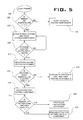
FIG. 5 illustrates a control strategy, which may be implemented in the controller 130 (FIG. 4). The control strategy begins with step 200 in which an operator starts an engine equipped with the system 100. At step 202, the controller 130 receives an input via the communication line 135 from the ambient air temperature sensor 134 and determines whether the ambient air temperature is less than or equal to −11° C. If the ambient air temperature is above −11° C., the control strategy ends with step 204 in which no heating components are activated because there is no danger of the reducing agent 104 freezing or being frozen. However, if the ambient air temperature is less than or equal to −11° C., the control strategy proceeds to step 206 in which the controller 130 sends control signals to activate the engine coolant line 112, the electric heater 116, and the third heating component 110 via the communication lines 113, 115, 111, respectively.
Activation of the engine coolant line 112 causes the engine coolant line valves 114 to open, thereby permitting engine coolant from the engine to circulate through and/or proximate the reducing agent tank 102. Activation of the electric heater 116 causes a power source (not shown) to provide power to the electric heater 116, thereby warming the reducing agent 104 proximate the electric heater 116. As the electric heater 116 warms up the reducing agent 104, the warmed reducing agent 104 begins to proliferate throughout the remainder of the tank 102, thereby facilitating further warming of the reducing agent 104. Activation of the third heating component 110 causes any frozen reducing agent 104 in the supply line 106 to thaw or prevents any reducing agent 104 in the supply line 106 from freezing.
The controller 130 then periodically monitors signal inputs from the engine coolant temperature sensor 132 until the sensor 132 indicates that engine coolant has reached a sufficient temperature, e.g., above −11° C., at which the engine coolant can heat frozen or freezing reducing agent 104. Once the sensor 132 indicates that the engine coolant has reached this threshold temperature, the electric heater 116 is deactivated in step 210 to prevent causing evaporation of the water portion of the reducing agent 104 due to overheating of the reducing agent 104. The engine coolant line 112 and the third heating component 110 remain activated as long as the temperature of the reducing agent 104 remains less than or equal to −11° C., as shown in steps 212 and 214. If the result of step 212 is that the reducing agent temperature sensor 120 indicates that the temperature of the reducing agent 104 is greater than −11° C., then the engine coolant line 112 is deactivated in step 216 to prevent overheating of the reducing agent 104. Deactivation of the engine coolant line 112 involves the step of closing at least one valve 114 to prevent any flow of engine coolant through or proximate the reducing agent tank 102.
The third heating component 110 remains activated as long as the ambient air temperature remains less than or equal to −11° C., as shown in- steps 218 and 222. If the result of step 218 is that the ambient air temperature sensor 134 indicates that the ambient air temperature is greater than −11° C., then the third heating component 110 is deactivated in step 220.
The controller 130 monitors inputs from the engine coolant temperature sensor 132, the reducing agent temperature sensor 120, and the ambient air temperature sensor 134 throughout the duration of engine use and provides control signals to the engine coolant line 112, the electric heater 116, and the third heating component 110 as necessary to prevent freezing of the reducing agent 104. For example, during use of the engine, if the ambient air temperature falls below or equal to −11° C., the controller 130 may start the control strategy at step 202 to ensure that the reducing agent 104 does not freeze. In another example, the engine may be placed into an idling state during use, at which point the engine coolant temperature may drop below the threshold temperature. If this scenario occurs, the controller 130 may start the control strategy at step 208 and activate the engine coolant line 112, the electric heater 116, and the third heating component 110. In yet another example, if the temperature of the reducing agent 104 falls below or equal to −11° C., the controller 130 may start the control strategy at step 212 and activate the engine coolant line 112 and the third heating component 110.
Industrial Applicability
The disclosed reducing agent heating system may be applicable to any engine operating in extreme cold environments, such as engines used with on-highway trucks, construction equipment, mining equipment, and power generation equipment, for example. The reducing agent heating system provides a dual energy heating strategy using both an electric heater and engine coolant lines such that emission control may be promoted efficiently.
In operation, the engine coolant line 112 and the electric heater 116 may heat frozen or freezing reducing agent 104 to return the reducing agent 104 to a liquid state in the tank 102. Moreover, the third heating component 110 may heat frozen or freezing reducing agent 104 to return the reducing agent 104 to a liquid state in the supply line 106.
After starting the engine, the controller 130 determines whether the ambient air temperature is less than or equal to −11° C. If the ambient air temperature is less than or equal to −11° C., the reducing agent 104 is highly likely to be frozen or freezing. The controller 130 then activates the engine coolant line 112, the electric heater 116, and the third heating component 110. The engine coolant line 112 and the electric heater 116 together form a dual energy heating mechanism for initially thawing frozen or freezing reducing agent 104 in the tank 102. The electric heater 116 is utilized to initially heat the reducing agent 104 because the engine coolant from the engine immediately after starting is potentially not warm enough to heat the reducing agent 104. Thus, both the engine coolant line 112 and the electric heater 116 are activated until the engine coolant reaches a threshold temperature at which the engine coolant may be solely used to heat the reducing agent 104. Once the engine coolant reaches this threshold temperature, the electric heater 116 is deactivated. After the electric heater 116 is deactivated to prevent overheating of the reducing agent 104, the engine coolant is used to warm the reducing agent 104 until the reducing agent temperature sensors 120 indicate that the temperature of the reducing agent 104 is greater than −11° C., at which point the engine coolant line 112 is deactivated by closing the valves 114 to prevent overheating of the reducing agent 104.
The third heating component 110 provides an additional protective measure for the system 100 by ensuring that the reducing agent 104 in the supply line 106 thaws and remains thawed. The third heating component 110 remains activated by the controller 130 until the ambient air temperature exceeds −11° C., at which point the third heating component 110 is deactivated because the danger of the reducing agent 104 freezing in the supply line 106 no longer exists.
By providing a dual energy heating mechanism, the system 100 can immediately begin to thaw the reducing agent 104 in the tank 102 without requiring engine warm-up after starting. The electric heater 116 provides an immediate thawing capability to the system 100 and then can be selectively deactivated to prevent overheating of the reducing agent 104 once the engine has sufficiently warmed. Therefore, the engine can more efficiently and quickly comply with exhaust emission standards after engine starting.
It will be apparent to those skilled in the art that various modifications and variations can be made to the disclosed reducing agent heating system without departing from the scope of the disclosure. Other embodiments of the reducing agent heating system will be apparent to those skilled in the art from consideration of the specification and practice of the reducing agent heating system disclosed herein. It is intended that the specification and examples be considered as exemplary only, with a true scope of the disclosure being indicated by the following claims and their equivalents.

Claims (7)

What is claimed is:
1. A reducing agent heating system for an engine, comprising:
a reducing agent storage container configured for housing a reducing agent and including a reducing agent supply line extending therefrom;
a first heating component positioned proximate said reducing agent storage container;
a second heating component disposed at least partially in said reducing agent storage container;
a third heating component disposed proximate said reducing agent supply line;
an ambient air temperature sensor coupled to a controller;
an engine coolant temperature sensor coupled to a controller; and
a reducing agent temperature sensor coupled to the controller, the controller being configured to control activation and deactivation of the first, second, and third heating components based on signals received from the ambient air temperature sensor, the engine coolant temperature sensor, and the reducing agent temperature sensor.
2. The reducing agent heating system of claim 1, wherein said second heating component comprises an electric heater positioned proximate said reducing agent.
3. The reducing agent heating system of claim 1, wherein said first heating component comprises at least one engine coolant line extending from the engine and positioned proximate said reducing agent storage container.
4. The reducing agent heating system of claim 3, wherein said engine coolant line includes at least one valve, said valve configured to control flow of engine coolant through said engine coolant line.
5. The reducing agent heating system of claim 1, wherein said first heating component comprises at least one engine coolant line extending from the engine and into said reducing agent storage container.
6. The reducing agent heating system of claim 5, wherein said engine coolant line includes at least one valve, said valve configured to control flow of engine coolant through said engine coolant line.
7. The reducing agent heating system of claim 1, wherein said third heating component comprises a wound wire heating element disposed circumferentially around at least a portion of said reducing agent supply line.
US12/070,498 2008-02-19 2008-02-19 Reducing agent heating system Active 2031-08-14 US8424777B2 (en)

Priority Applications (1)

Application Number Priority Date Filing Date Title
US12/070,498 US8424777B2 (en) 2008-02-19 2008-02-19 Reducing agent heating system

Applications Claiming Priority (1)

Application Number Priority Date Filing Date Title
US12/070,498 US8424777B2 (en) 2008-02-19 2008-02-19 Reducing agent heating system

Publications (2)

Publication Number Publication Date
US20090205320A1 US20090205320A1 (en) 2009-08-20
US8424777B2 true US8424777B2 (en) 2013-04-23

Family

ID=40953822

Family Applications (1)

Application Number Title Priority Date Filing Date
US12/070,498 Active 2031-08-14 US8424777B2 (en) 2008-02-19 2008-02-19 Reducing agent heating system

Country Status (1)

Country Link
US (1) US8424777B2 (en)

Cited By (4)

* Cited by examiner, † Cited by third party
Publication number Priority date Publication date Assignee Title
US20110027740A1 (en) * 2008-03-11 2011-02-03 Inergy Automotive Systems Research (Société Anonym Method for Heating a SCR System
US20130330065A1 (en) * 2010-12-08 2013-12-12 Otfried Schwarzkopf Heatable fluid line, use thereof and method for producing same
US9188043B1 (en) * 2014-04-24 2015-11-17 Fca Us Llc Techniques for thawing a reductant injector and reductant tank prior to an injection attempt
US10245534B2 (en) 2015-05-28 2019-04-02 Shaw Development, Llc Filter inline heater

Families Citing this family (17)

* Cited by examiner, † Cited by third party
Publication number Priority date Publication date Assignee Title
JP5139765B2 (en) * 2007-10-12 2013-02-06 ボッシュ株式会社 Control device and control method for reducing agent supply system
US8455784B2 (en) * 2008-05-07 2013-06-04 GM Global Technology Operations LLC Method and system for welding workpieces
RU2547544C2 (en) * 2009-12-24 2015-04-10 Инержи Отомоутив Системз Рисерч (Сосьете Аноним) Container and tank, which are equipped with self-adjusting heating element
US8495868B2 (en) * 2010-03-22 2013-07-30 Caterpillar Inc. Control strategy for heated fluid lines
CN103097166B (en) 2010-06-15 2016-04-27 肖恩发展有限责任公司 For the groove module interface of fluid reservoir
US8822887B2 (en) 2010-10-27 2014-09-02 Shaw Arrow Development, LLC Multi-mode heater for a diesel emission fluid tank
US20120275773A1 (en) * 2011-04-26 2012-11-01 Floyd Ryan A Reductant Heater
US20130026244A1 (en) * 2011-07-28 2013-01-31 Cnh America Llc Work vehicle heating system and method
US20130186349A1 (en) * 2012-01-24 2013-07-25 Caterpillar Inc. Reductant supply line heating system
US9458746B2 (en) * 2013-03-01 2016-10-04 Cummins Emission Solutions Inc. Systems and techniques for heating urea injection systems
US8959903B2 (en) 2013-03-01 2015-02-24 Cummins Emission Solutions Inc. Systems and techniques for heating urea injection systems
US9016043B2 (en) * 2013-03-14 2015-04-28 Tenneco Automotive Operating Company Inc. Exhaust treatment system with urea temperature rationality diagnostic
JP5685679B1 (en) * 2014-02-26 2015-03-18 株式会社小松製作所 Work vehicle
USD729722S1 (en) 2014-05-28 2015-05-19 Shaw Development LLC Diesel emissions fluid tank floor
USD729141S1 (en) 2014-05-28 2015-05-12 Shaw Development LLC Diesel emissions fluid tank
CN112554998B (en) * 2020-11-30 2022-08-30 潍柴动力股份有限公司 Anti-adhesion control method and device for urea box heating electromagnetic valve and storage medium
CN115949485B (en) * 2023-03-13 2023-06-13 中国重汽集团济南动力有限公司 Automobile urea temperature control system, control method and automobile

Citations (29)

* Cited by examiner, † Cited by third party
Publication number Priority date Publication date Assignee Title
US5063513A (en) * 1990-06-15 1991-11-05 Nartron Corporation Vehicle preheater control
US5845485A (en) * 1996-07-16 1998-12-08 Lynntech, Inc. Method and apparatus for injecting hydrogen into a catalytic converter
US6063350A (en) 1997-04-02 2000-05-16 Clean Diesel Technologies, Inc. Reducing nox emissions from an engine by temperature-controlled urea injection for selective catalytic reduction
US20020088220A1 (en) * 1999-07-19 2002-07-11 Manfred Weigl Device and method for exhaust-gas aftertreatment in an internal-combustion engine
US6662553B2 (en) * 2000-10-16 2003-12-16 Engelhard Corporation Control system for mobile NOx SCR applications
US6681811B2 (en) 2001-05-17 2004-01-27 Ford Global Technologies, Llc Fuel and reductant delivery system
US6739126B2 (en) 2001-12-03 2004-05-25 Purem Abgassystem Gmbh & Co.Kg Reducing agent dosing device
US6810661B2 (en) 2002-08-09 2004-11-02 Ford Global Technologies, Llc Method and system for freeze protecting liquid NOx reductants for vehicle application
US20040226285A1 (en) * 2003-05-14 2004-11-18 Gomulka Ted Gene Heater system for diesel engines having a selective catalytic reduction system
US20060048503A1 (en) * 2003-05-26 2006-03-09 Martin Havers Device for clearing a supply pipe of a reducing agent that has previously gone from a first phase to a second phase then back again
US20060213473A1 (en) * 2003-12-04 2006-09-28 Volvo Lastvagnar Ab Device for heating
US20070079599A1 (en) 2003-09-05 2007-04-12 Nissan Diesel Motor Co., Ltd. Exhaust gas purifying apparatus in engine
US20070092413A1 (en) 2003-09-19 2007-04-26 Nissan Diesel Motor Co., Ltd. Engine exhaust emission purification apparatus
JP2007113403A (en) * 2005-10-18 2007-05-10 Nissan Diesel Motor Co Ltd Outside air temperature detecting device and exhaust emission control device
US20070157602A1 (en) * 2005-09-26 2007-07-12 Dbk David + Baader Gmbh Tank system with a main tank and a melting device having a melt tank
US20070199308A1 (en) * 2004-10-29 2007-08-30 Nissan Diesel Motor Co., Ltd. Exhaust emission purifying apparatus for engine
US7293408B2 (en) 2003-02-07 2007-11-13 Daimlerchrysler Ag Exhaust gas treatment system and utility vehicle with an exhaust gas treatment system
DE102006046900A1 (en) * 2006-10-04 2008-04-10 Robert Bosch Gmbh Method for operating an internal combustion engine
US20080110158A1 (en) * 2005-08-24 2008-05-15 Nissan Diesel Motor Co., Ltd. Exhaust emission purifying apparatus for engine
US20080179414A1 (en) * 2007-01-30 2008-07-31 Rainer Bentz Heating device for heating a storage device for a complex salt and method and device for operating the heating device
US20080202473A1 (en) * 2007-02-27 2008-08-28 Ford Global Technologies Llc Method and apparatus for rapidly thawing frozen nox reductant
US20080223021A1 (en) * 2007-03-15 2008-09-18 Furqan Shaikh Ammonia vapor management system and method
US20090028533A1 (en) * 2005-07-12 2009-01-29 Eichenauer Heizelemente Gmbh & Co. Kg Tank Heating System
US20090139214A1 (en) * 2007-11-30 2009-06-04 Perkins Engines Company Limited Exhaust Treatment System Having A Diverter Valve
US20100050606A1 (en) * 2008-09-04 2010-03-04 Fulks Gary C Urea tank assembly
US20100095653A1 (en) * 2008-10-22 2010-04-22 Caterpillar Inc. System and method for heating a reducing agent associated with a reducing agent distribution system
US20100199647A1 (en) * 2009-02-10 2010-08-12 Delphi Technologies, Inc. Heat urea strainer for diesel engine
US20110000196A1 (en) * 2008-03-07 2011-01-06 Hiroyuki Kasahara Control device of reducing agent supply apparatus, reducing agent collection method, and exhaust gas purification apparatus
US20110030349A1 (en) * 2009-08-04 2011-02-10 International Engine Intellectual Property Company, Llc Quick-heating of a urea supply conduit for an engine exhaust after-treatment system

Patent Citations (32)

* Cited by examiner, † Cited by third party
Publication number Priority date Publication date Assignee Title
US5063513A (en) * 1990-06-15 1991-11-05 Nartron Corporation Vehicle preheater control
US5845485A (en) * 1996-07-16 1998-12-08 Lynntech, Inc. Method and apparatus for injecting hydrogen into a catalytic converter
US6063350A (en) 1997-04-02 2000-05-16 Clean Diesel Technologies, Inc. Reducing nox emissions from an engine by temperature-controlled urea injection for selective catalytic reduction
US20020088220A1 (en) * 1999-07-19 2002-07-11 Manfred Weigl Device and method for exhaust-gas aftertreatment in an internal-combustion engine
US6519935B2 (en) 1999-07-19 2003-02-18 Siemens Aktiengesellschaft Device and method for exhaust-gas aftertreatment in an internal-combustion engine
US6662553B2 (en) * 2000-10-16 2003-12-16 Engelhard Corporation Control system for mobile NOx SCR applications
US6681811B2 (en) 2001-05-17 2004-01-27 Ford Global Technologies, Llc Fuel and reductant delivery system
US6739126B2 (en) 2001-12-03 2004-05-25 Purem Abgassystem Gmbh & Co.Kg Reducing agent dosing device
US6810661B2 (en) 2002-08-09 2004-11-02 Ford Global Technologies, Llc Method and system for freeze protecting liquid NOx reductants for vehicle application
US7293408B2 (en) 2003-02-07 2007-11-13 Daimlerchrysler Ag Exhaust gas treatment system and utility vehicle with an exhaust gas treatment system
US20040226285A1 (en) * 2003-05-14 2004-11-18 Gomulka Ted Gene Heater system for diesel engines having a selective catalytic reduction system
US6901748B2 (en) 2003-05-14 2005-06-07 Detroit Diesel Corporation Heater system for diesel engines having a selective catalytic reduction system
US20060048503A1 (en) * 2003-05-26 2006-03-09 Martin Havers Device for clearing a supply pipe of a reducing agent that has previously gone from a first phase to a second phase then back again
US20070079599A1 (en) 2003-09-05 2007-04-12 Nissan Diesel Motor Co., Ltd. Exhaust gas purifying apparatus in engine
US20070092413A1 (en) 2003-09-19 2007-04-26 Nissan Diesel Motor Co., Ltd. Engine exhaust emission purification apparatus
US20060213473A1 (en) * 2003-12-04 2006-09-28 Volvo Lastvagnar Ab Device for heating
US20070199308A1 (en) * 2004-10-29 2007-08-30 Nissan Diesel Motor Co., Ltd. Exhaust emission purifying apparatus for engine
US20090028533A1 (en) * 2005-07-12 2009-01-29 Eichenauer Heizelemente Gmbh & Co. Kg Tank Heating System
US20080110158A1 (en) * 2005-08-24 2008-05-15 Nissan Diesel Motor Co., Ltd. Exhaust emission purifying apparatus for engine
US20070157602A1 (en) * 2005-09-26 2007-07-12 Dbk David + Baader Gmbh Tank system with a main tank and a melting device having a melt tank
JP2007113403A (en) * 2005-10-18 2007-05-10 Nissan Diesel Motor Co Ltd Outside air temperature detecting device and exhaust emission control device
DE102006046900A1 (en) * 2006-10-04 2008-04-10 Robert Bosch Gmbh Method for operating an internal combustion engine
US20080179414A1 (en) * 2007-01-30 2008-07-31 Rainer Bentz Heating device for heating a storage device for a complex salt and method and device for operating the heating device
US20080202473A1 (en) * 2007-02-27 2008-08-28 Ford Global Technologies Llc Method and apparatus for rapidly thawing frozen nox reductant
US7930878B2 (en) * 2007-02-27 2011-04-26 Ford Global Technologies, Llc Method and apparatus for rapidly thawing frozen NOx reductant
US20080223021A1 (en) * 2007-03-15 2008-09-18 Furqan Shaikh Ammonia vapor management system and method
US20090139214A1 (en) * 2007-11-30 2009-06-04 Perkins Engines Company Limited Exhaust Treatment System Having A Diverter Valve
US20110000196A1 (en) * 2008-03-07 2011-01-06 Hiroyuki Kasahara Control device of reducing agent supply apparatus, reducing agent collection method, and exhaust gas purification apparatus
US20100050606A1 (en) * 2008-09-04 2010-03-04 Fulks Gary C Urea tank assembly
US20100095653A1 (en) * 2008-10-22 2010-04-22 Caterpillar Inc. System and method for heating a reducing agent associated with a reducing agent distribution system
US20100199647A1 (en) * 2009-02-10 2010-08-12 Delphi Technologies, Inc. Heat urea strainer for diesel engine
US20110030349A1 (en) * 2009-08-04 2011-02-10 International Engine Intellectual Property Company, Llc Quick-heating of a urea supply conduit for an engine exhaust after-treatment system

Non-Patent Citations (1)

* Cited by examiner, † Cited by third party
Title
Matsunaga, JP2007113403 English machine translation, May 10, 2007. *

Cited By (6)

* Cited by examiner, † Cited by third party
Publication number Priority date Publication date Assignee Title
US20110027740A1 (en) * 2008-03-11 2011-02-03 Inergy Automotive Systems Research (Société Anonym Method for Heating a SCR System
US20130330065A1 (en) * 2010-12-08 2013-12-12 Otfried Schwarzkopf Heatable fluid line, use thereof and method for producing same
US9360147B2 (en) * 2010-12-08 2016-06-07 Voss Automotive Gmbh Heatable fluid line, use thereof and method for producing same
US9188043B1 (en) * 2014-04-24 2015-11-17 Fca Us Llc Techniques for thawing a reductant injector and reductant tank prior to an injection attempt
US10245534B2 (en) 2015-05-28 2019-04-02 Shaw Development, Llc Filter inline heater
US11318401B2 (en) 2015-05-28 2022-05-03 Shaw Development, Llc Filter inline heater

Also Published As

Publication number Publication date
US20090205320A1 (en) 2009-08-20

Similar Documents

Publication Publication Date Title
US8424777B2 (en) Reducing agent heating system
US8234854B2 (en) System and method for heating a reducing agent associated with a reducing agent distribution system
US5884475A (en) Method and device for introducing liquid into an exhaust-gas purification system
EP1827887B1 (en) Method and system for storing an additive and injecting it into the exhaust gases of an engine
EP1691046B1 (en) Exhaust emission purification apparatus for an internal combustion engine
EP1388648B1 (en) A Method and System for Freeze Protecting Liquid NOx Reductants for Vehicle Application
US9968886B2 (en) Dual catalyst heating system
JP3686670B1 (en) Exhaust purification device
JP5573351B2 (en) SCR system
KR102309229B1 (en) Combustion engine
US8096112B2 (en) Exhaust after-treatment system having a secondary tank
EP2065578A1 (en) Heating system for chemical used in exhaust purification system
US20090139214A1 (en) Exhaust Treatment System Having A Diverter Valve
US8438838B2 (en) Fuel-fired burner and heat exchanger system for heating a NOx reducing agent supply tank
JP2010138883A (en) Control device for exhaust emission control system
GB2447110A (en) METHOD AND APPARATUS FOR THAWING FROZEN NOx REDUCTANT
US8495868B2 (en) Control strategy for heated fluid lines
RU2546386C2 (en) Method and device for cooling of scr-system proportioners
GB2533099A (en) Method for providing heating to a diesel exhaust fluid (DEF) tank and diesel exhaust fluid (DEF) tank
EP2273082A1 (en) Apparatus for maintening a urea solution in a liquid state for treatment of diesel exhaust
CN112727571B (en) System and method for heating a reducing agent
US20180128140A1 (en) Urea-water solution heating and cooling devices for construction equipment
KR20230053889A (en) Refrigerant Control Method of Urea Injector Cooling System of Exchanging Heat with Urea Tank
SE541586C2 (en) An arrangement for heating and providing a reducing agent to an exhaust treatment device

Legal Events

Date Code Title Description
AS Assignment

Owner name: CATERPILLAR INC., ILLINOIS

Free format text: ASSIGNMENT OF ASSIGNORS INTEREST;ASSIGNORS:MOKIRE, MAHESH K.;SINHA, RISHABH;REEL/FRAME:020870/0515;SIGNING DATES FROM 20080331 TO 20080423

Owner name: CATERPILLAR INC., ILLINOIS

Free format text: ASSIGNMENT OF ASSIGNORS INTEREST;ASSIGNORS:MOKIRE, MAHESH K.;SINHA, RISHABH;SIGNING DATES FROM 20080331 TO 20080423;REEL/FRAME:020870/0515

STCF Information on status: patent grant

Free format text: PATENTED CASE

FPAY Fee payment

Year of fee payment: 4

MAFP Maintenance fee payment

Free format text: PAYMENT OF MAINTENANCE FEE, 8TH YEAR, LARGE ENTITY (ORIGINAL EVENT CODE: M1552); ENTITY STATUS OF PATENT OWNER: LARGE ENTITY

Year of fee payment: 8