US8430444B1 - Vehicle covering system - Google Patents
Vehicle covering system Download PDFInfo
- Publication number
- US8430444B1 US8430444B1 US13/269,934 US201113269934A US8430444B1 US 8430444 B1 US8430444 B1 US 8430444B1 US 201113269934 A US201113269934 A US 201113269934A US 8430444 B1 US8430444 B1 US 8430444B1
- Authority
- US
- United States
- Prior art keywords
- doors
- vehicle
- covering
- seat
- pair
- Prior art date
- Legal status (The legal status is an assumption and is not a legal conclusion. Google has not performed a legal analysis and makes no representation as to the accuracy of the status listed.)
- Active, expires
Links
Images


Classifications
-
- B—PERFORMING OPERATIONS; TRANSPORTING
- B62—LAND VEHICLES FOR TRAVELLING OTHERWISE THAN ON RAILS
- B62J—CYCLE SADDLES OR SEATS; AUXILIARY DEVICES OR ACCESSORIES SPECIALLY ADAPTED TO CYCLES AND NOT OTHERWISE PROVIDED FOR, e.g. ARTICLE CARRIERS OR CYCLE PROTECTORS
- B62J17/00—Weather guards for riders; Fairings or stream-lining parts not otherwise provided for
- B62J17/08—Hoods protecting the rider
-
- B—PERFORMING OPERATIONS; TRANSPORTING
- B60—VEHICLES IN GENERAL
- B60J—WINDOWS, WINDSCREENS, NON-FIXED ROOFS, DOORS, OR SIMILAR DEVICES FOR VEHICLES; REMOVABLE EXTERNAL PROTECTIVE COVERINGS SPECIALLY ADAPTED FOR VEHICLES
- B60J7/00—Non-fixed roofs; Roofs with movable panels, e.g. rotary sunroofs
- B60J7/08—Non-fixed roofs; Roofs with movable panels, e.g. rotary sunroofs of non-sliding type, i.e. movable or removable roofs or panels, e.g. let-down tops or roofs capable of being easily detached or of assuming a collapsed or inoperative position
- B60J7/10—Non-fixed roofs; Roofs with movable panels, e.g. rotary sunroofs of non-sliding type, i.e. movable or removable roofs or panels, e.g. let-down tops or roofs capable of being easily detached or of assuming a collapsed or inoperative position readily detachable, e.g. tarpaulins with frames, or fastenings for tarpaulins
- B60J7/106—Non-fixed roofs; Roofs with movable panels, e.g. rotary sunroofs of non-sliding type, i.e. movable or removable roofs or panels, e.g. let-down tops or roofs capable of being easily detached or of assuming a collapsed or inoperative position readily detachable, e.g. tarpaulins with frames, or fastenings for tarpaulins readily detachable hard-tops
-
- B—PERFORMING OPERATIONS; TRANSPORTING
- B62—LAND VEHICLES FOR TRAVELLING OTHERWISE THAN ON RAILS
- B62K—CYCLES; CYCLE FRAMES; CYCLE STEERING DEVICES; RIDER-OPERATED TERMINAL CONTROLS SPECIALLY ADAPTED FOR CYCLES; CYCLE AXLE SUSPENSIONS; CYCLE SIDE-CARS, FORECARS, OR THE LIKE
- B62K5/00—Cycles with handlebars, equipped with three or more main road wheels
- B62K5/01—Motorcycles with four or more wheels
-
- B—PERFORMING OPERATIONS; TRANSPORTING
- B62—LAND VEHICLES FOR TRAVELLING OTHERWISE THAN ON RAILS
- B62J—CYCLE SADDLES OR SEATS; AUXILIARY DEVICES OR ACCESSORIES SPECIALLY ADAPTED TO CYCLES AND NOT OTHERWISE PROVIDED FOR, e.g. ARTICLE CARRIERS OR CYCLE PROTECTORS
- B62J17/00—Weather guards for riders; Fairings or stream-lining parts not otherwise provided for
- B62J17/08—Hoods protecting the rider
- B62J17/086—Frame mounted hoods specially adapted for motorcycles or the like
Definitions
- the disclosure relates to vehicle covering devices and more particularly pertains to a new covering device for a modified version of an all terrain vehicle for covering a person who is operating an all terrain type vehicle.
- An embodiment of the disclosure meets the needs presented above by generally comprising a vehicle that has a front fender, a rear fender, a pair of floor boards and a seat.
- the seat is positioned between the front and rear fenders and between the floor boards.
- a covering is removably positioned on the vehicle and is coextensive with the front fender, the rear fender and the floor boards to shield a person seated on the seat.
- a pair of doors is removably attached to the vehicle and each of the doors is pivotally coupled to one of a pair of side edges of the front fender.
- Each of a pair of latches is mounted one of the doors and releasably engages the rear fender to retain the doors in a closed position extending between the front and rear fenders.
- An embodiment of the disclosure further meets the needs presented above by generally comprising a vehicle that has a front fender, a rear fender, a pair of floor boards and a seat.
- the seat is positioned between the front and rear fenders and between the floor boards.
- a covering is removably positioned on the vehicle and is coextensive with the front fender, the rear fender and the floor boards to shield a person seated on the seat.
- the covering includes a windshield that is attached to and extends upwardly from an upper portion of the front fender.
- the windshield has a pair of lateral edges each having a lateral window hingedly coupled thereto.
- the seat is positioned between the lateral edges.
- An upper cover includes a top wall and a rear wall. The rear wall is attached to and extends upwardly from the rear fender. The top wall extends over the seat and is coupled to the top edge of the windshield.
- FIG. 1 is a front perspective view of a vehicle covering system according to an embodiment of the disclosure.
- FIG. 2 is a side view of an embodiment of the disclosure.
- FIG. 3A is a front perspective view of an embodiment of a covering of the disclosure.
- FIG. 3B is a front perspective view of an embodiment of a covering of the disclosure.
- FIG. 4 is a cross-sectional view of an embodiment of the disclosure taken along line 4 - 4 of FIG. 5 .
- FIG. 5 is an enlarged exploded view of an embodiment of the disclosure of the area designated “5” of FIG. 2 .
- FIG. 6 is a front view of an embodiment of the disclosure.
- FIG. 7 is an enlarged perspective view of an embodiment of a latch of the disclosure.
- FIG. 8 is a perspective view of an embodiment of the covering of the disclosure.
- FIG. 9 is a side view of an embodiment of a door and lateral window of the disclosure.
- FIG. 10 is a rear view of an embodiment of the disclosure.
- FIG. 11 is rear view of an embodiment of the disclosure.
- FIG. 12 is a side view of a door of an embodiment of the disclosure.
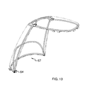
- FIG. 13 is a perspective view of an embodiment of a covering of the disclosure.
- FIG. 14 is a rear view of an embodiment of the disclosure.
- FIGS. 1 through 14 With reference now to the drawings, and in particular to FIGS. 1 through 14 thereof, a new vehicle covering device embodying the principles and concepts of an embodiment of the disclosure and generally designated by the reference numeral 10 will be described.
- the vehicle covering system 14 generally comprises a vehicle 12 that has a front fender 14 , a rear fender 16 , a pair of floor boards 18 and a seat 20 .
- the seat 20 is positioned between the front 14 and rear 16 fenders and between the floor boards 18 .
- the vehicle is modeled after an all terrain vehicle such that the seat is elongated and intended to be straddled.
- the turning mechanism will include handlebars instead of a steering wheel.
- throttle, brake and other controls would likely be mounted on the handlebars.
- the vehicle may be a conventional all terrain vehicle or it may be partially or significantly modified depending on need and usage.
- the vehicle 12 may differ from off road all terrain vehicles by including a wider wheelbase, anti-lock disc brakes, headlights, brake lights, turn signals, larger wheels, a lower ground clearance, rear view mirrors and climate control, such as air conditioning and heating, for the purpose of making the all terrain vehicle safer for street driving and in particular more comfortable for driving at highway rated speeds. Such modifications would typically render the vehicle 12 unsuitable for off road driving due to low clearances and wheels not configured to engage rough terrain.
- the vehicle 12 may be powered by a conventional gasoline powered engine, an electric motor, or a hybrid power supply combining the two.
- a covering 22 is removably positioned on the vehicle 12 to help encapsulate a rider positioned on the seat 20 .
- the covering 22 is coextensive with the front fender 14 , the rear fender 16 and the floor boards 18 to facilitate the encapsulation of the seat 20 within the covering 22 .
- the covering 22 includes a windshield 24 that is attached to and extends upwardly from an upper portion of the front fender 14 .
- the windshield 24 has a pair of lateral edges 26 and the seat 20 is positioned between the lateral edges 26 .
- a pair of lateral windows 28 is provided and each of the lateral windows 28 is hingedly coupled to one of the lateral edges 26 . This allows the lateral windows 28 to be opened as needed for entering or leaving the seat 20 .
- the lateral windows 28 may be constructed such that they are easily removable from the windshield 24 . It should be understood that the windshield 24 may have other configurations than shown in the Figures such as having a front edge coming to a point or being angled more from the front edge rearward to promote more aerodynamic advantages.
- An upper cover 30 includes a top wall 32 and a rear wall 34 .
- the rear wall 34 is attached to and extends upwardly from the rear fender 16 , while the top wall 32 extends over the seat 20 and is coupled to the top edge of the windshield 24 .
- the means of coupling the top wall 32 to the windshield 24 may be effected by way of clamps 36 , pins 38 or other conventional means.
- FIG. 8 depicts an upper cover 30 having pivotally coupled sections 40 covered by a flexible tarp to allow the upper cover 30 to be collapsed if not needed or desired while FIG.
- FIG. 10 depicts an embodiment of the cover 30 wherein the top 32 and rear 34 walls are comprised of a transparent material to allow a rider of the vehicle 12 to clearly see in all directions.
- a seal 42 may be positioned on the windshield 24 and the lateral windows 28 to inhibit air and water from flowing between the windshield 24 and lateral windows 28 and the upper cover 30 .
- FIG. 11 depicts a window 56 which may be positioned in the upper cover 30 . This will allow a person to more easily be able to see rearward while driving in reverse.
- a pair of doors 44 is removably attached to the vehicle 12 .
- Each of the doors 44 is pivotally coupled to one of a pair of side edges of the front fender 14 .
- the doors 44 are each alignable with one of the lateral windows 28 and each is couplable with an aligned one of the lateral windows 28 such that each of the doors 44 and the aligned one of the lateral windows 28 may be opened or closed together.
- FIG. 9 shows a pin mechanism 45 which may be used to couple a lateral window 28 to an associated door 44 .
- FIG. 7 includes an enlarged view of a conventional latch 46 , which is one of a pair of latches 46 , that may be mounted on the doors 44 and releasably engaged with the rear fender 16 to retain the doors 44 in a closed position extending between the front 14 and rear 16 fenders.
- Each of the doors 44 has a bottom edge 48 and each of the floor boards 18 may have a seal 50 thereon against which the doors 44 , adjacent their bottom edges, may abut when closed to prevent water and air from traveling between the floorboards 18 and the doors 44 .
- FIGS. 12-14 teach an embodiment that may be more readily retrofitted to a conventional all terrain vehicle.
- this embodiment will not include a vehicle having mounts welded thereto and therefore may include an upper cover 67 which includes a catch 64 for engaging latch 63 of a door 61 .
- the door 61 includes seal 65 .
- the door 61 includes couplers 62 that are extendable into sleeves 58 mounted on support rods 68 that extend downwardly from a windshield 69 .
- Each side of the windshield 69 includes a pair of support rods 68 as is shown in FIG. 14 which extend downwardly and over the footrest 74 . This allows a housing 59 to be mounted on the support bars 58 .
- the housing 59 includes a bottom wall 70 , front wall 71 , inner wall 72 and rear wall 73 which, in conjunction with the door 61 , encompasses a person's foot.
- a bracket 60 extends through the housing to engage the footrest 74 of the all terrain vehicle.
- the covering 22 is mounted on the vehicle 12 as stated above and as described in the Figures.
- the covering 22 allows a person to ride the vehicle 12 at relatively high speeds in comfort without concern about the elements.
Abstract
A vehicle covering system includes a vehicle that has a front fender, a rear fender, a pair of floor boards and a seat. The seat is positioned between the front and rear fenders and between the floor boards. A covering is removably positioned on the vehicle and is coextensive with the front fender, the rear fender and the floor boards to shield a person seated on the seat. A pair of doors is removably attached to the vehicle and each of the doors is pivotally coupled to one of a pair of side edges of the front fender. Each of a pair of latches is mounted one of the doors and releasably engages the rear fender to retain the doors in a closed position extending between the front and rear fenders.
Description
The disclosure relates to vehicle covering devices and more particularly pertains to a new covering device for a modified version of an all terrain vehicle for covering a person who is operating an all terrain type vehicle.
An embodiment of the disclosure meets the needs presented above by generally comprising a vehicle that has a front fender, a rear fender, a pair of floor boards and a seat. The seat is positioned between the front and rear fenders and between the floor boards. A covering is removably positioned on the vehicle and is coextensive with the front fender, the rear fender and the floor boards to shield a person seated on the seat. A pair of doors is removably attached to the vehicle and each of the doors is pivotally coupled to one of a pair of side edges of the front fender. Each of a pair of latches is mounted one of the doors and releasably engages the rear fender to retain the doors in a closed position extending between the front and rear fenders.
An embodiment of the disclosure further meets the needs presented above by generally comprising a vehicle that has a front fender, a rear fender, a pair of floor boards and a seat. The seat is positioned between the front and rear fenders and between the floor boards. A covering is removably positioned on the vehicle and is coextensive with the front fender, the rear fender and the floor boards to shield a person seated on the seat. The covering includes a windshield that is attached to and extends upwardly from an upper portion of the front fender. The windshield has a pair of lateral edges each having a lateral window hingedly coupled thereto. The seat is positioned between the lateral edges. An upper cover includes a top wall and a rear wall. The rear wall is attached to and extends upwardly from the rear fender. The top wall extends over the seat and is coupled to the top edge of the windshield.
There has thus been outlined, rather broadly, the more important features of the disclosure in order that the detailed description thereof that follows may be better understood, and in order that the present contribution to the art may be better appreciated. There are additional features of the disclosure that will be described hereinafter and which will form the subject matter of the claims appended hereto.
The objects of the disclosure, along with the various features of novelty which characterize the disclosure, are pointed out with particularity in the claims annexed to and forming a part of this disclosure.
The disclosure will be better understood and objects other than those set forth above will become apparent when consideration is given to the following detailed description thereof. Such description makes reference to the annexed drawings wherein:
With reference now to the drawings, and in particular to FIGS. 1 through 14 thereof, a new vehicle covering device embodying the principles and concepts of an embodiment of the disclosure and generally designated by the reference numeral 10 will be described.
As best illustrated in FIGS. 1 through 10 , the vehicle covering system 14 generally comprises a vehicle 12 that has a front fender 14, a rear fender 16, a pair of floor boards 18 and a seat 20. The seat 20 is positioned between the front 14 and rear 16 fenders and between the floor boards 18. The vehicle is modeled after an all terrain vehicle such that the seat is elongated and intended to be straddled. Moreover, the turning mechanism will include handlebars instead of a steering wheel. Additionally, throttle, brake and other controls would likely be mounted on the handlebars. It should be understood that the vehicle may be a conventional all terrain vehicle or it may be partially or significantly modified depending on need and usage. In particular, the vehicle 12 may differ from off road all terrain vehicles by including a wider wheelbase, anti-lock disc brakes, headlights, brake lights, turn signals, larger wheels, a lower ground clearance, rear view mirrors and climate control, such as air conditioning and heating, for the purpose of making the all terrain vehicle safer for street driving and in particular more comfortable for driving at highway rated speeds. Such modifications would typically render the vehicle 12 unsuitable for off road driving due to low clearances and wheels not configured to engage rough terrain. Additionally, the vehicle 12 may be powered by a conventional gasoline powered engine, an electric motor, or a hybrid power supply combining the two.
A covering 22 is removably positioned on the vehicle 12 to help encapsulate a rider positioned on the seat 20. The covering 22 is coextensive with the front fender 14, the rear fender 16 and the floor boards 18 to facilitate the encapsulation of the seat 20 within the covering 22. The covering 22 includes a windshield 24 that is attached to and extends upwardly from an upper portion of the front fender 14. The windshield 24 has a pair of lateral edges 26 and the seat 20 is positioned between the lateral edges 26. A pair of lateral windows 28 is provided and each of the lateral windows 28 is hingedly coupled to one of the lateral edges 26. This allows the lateral windows 28 to be opened as needed for entering or leaving the seat 20. The lateral windows 28 may be constructed such that they are easily removable from the windshield 24. It should be understood that the windshield 24 may have other configurations than shown in the Figures such as having a front edge coming to a point or being angled more from the front edge rearward to promote more aerodynamic advantages.
An upper cover 30 includes a top wall 32 and a rear wall 34. The rear wall 34 is attached to and extends upwardly from the rear fender 16, while the top wall 32 extends over the seat 20 and is coupled to the top edge of the windshield 24. As can be seen in FIGS. 3A and 3B , the means of coupling the top wall 32 to the windshield 24 may be effected by way of clamps 36, pins 38 or other conventional means. Also, FIG. 8 depicts an upper cover 30 having pivotally coupled sections 40 covered by a flexible tarp to allow the upper cover 30 to be collapsed if not needed or desired while FIG. 10 depicts an embodiment of the cover 30 wherein the top 32 and rear 34 walls are comprised of a transparent material to allow a rider of the vehicle 12 to clearly see in all directions. A seal 42 may be positioned on the windshield 24 and the lateral windows 28 to inhibit air and water from flowing between the windshield 24 and lateral windows 28 and the upper cover 30. FIG. 11 depicts a window 56 which may be positioned in the upper cover 30. This will allow a person to more easily be able to see rearward while driving in reverse.
A pair of doors 44 is removably attached to the vehicle 12. Each of the doors 44 is pivotally coupled to one of a pair of side edges of the front fender 14. The doors 44 are each alignable with one of the lateral windows 28 and each is couplable with an aligned one of the lateral windows 28 such that each of the doors 44 and the aligned one of the lateral windows 28 may be opened or closed together. FIG. 9 shows a pin mechanism 45 which may be used to couple a lateral window 28 to an associated door 44. FIG. 7 includes an enlarged view of a conventional latch 46, which is one of a pair of latches 46, that may be mounted on the doors 44 and releasably engaged with the rear fender 16 to retain the doors 44 in a closed position extending between the front 14 and rear 16 fenders. Each of the doors 44 has a bottom edge 48 and each of the floor boards 18 may have a seal 50 thereon against which the doors 44, adjacent their bottom edges, may abut when closed to prevent water and air from traveling between the floorboards 18 and the doors 44.
In use, the covering 22 is mounted on the vehicle 12 as stated above and as described in the Figures. The covering 22 allows a person to ride the vehicle 12 at relatively high speeds in comfort without concern about the elements.
With respect to the above description then, it is to be realized that the optimum dimensional relationships for the parts of an embodiment enabled by the disclosure, to include variations in size, materials, shape, form, function and manner of operation, assembly and use, are deemed readily apparent and obvious to one skilled in the art, and all equivalent relationships to those illustrated in the drawings and described in the specification are intended to be encompassed by an embodiment of the disclosure.
Therefore, the foregoing is considered as illustrative only of the principles of the disclosure. Further, since numerous modifications and changes will readily occur to those skilled in the art, it is not desired to limit the disclosure to the exact construction and operation shown and described, and accordingly, all suitable modifications and equivalents may be resorted to, falling within the scope of the disclosure.
Claims (11)
1. A personal vehicle and covering system comprising:
a vehicle having a front fender, a rear fender, a pair of floor boards and a seat, said seat being positioned between said front and rear fenders and between said floor boards;
a covering being removably positioned on said vehicle, said covering being coextensive with said front fender, said rear fender and said floor boards to shield a person seated on said seat;
a pair of doors being removably attached to said vehicle, each of said doors being pivotally coupled to one of a pair of side edges of said front fender; and
a pair of latches, each of said latches being mounted one of said doors and releasably engaging said rear fender to retain said doors in a closed position extending between said front and rear fenders.
2. The system according to claim 1 , wherein said covering including:
a windshield being attached to and extending upwardly from an upper portion of said front fender, said windshield having a pair of lateral edges; and
an upper cover including a top wall and a rear wall, said rear wall being attached to and extending upwardly from said rear fender, said top wall extending over said seat and being coupled to said top edge of said windshield.
3. The system according to claim 2 , wherein said covering further includes a pair of lateral windows, each of said lateral windows being hingedly coupled to one of said lateral edges, said seat being positioned between said lateral edges.
4. The system according to claim 3 , wherein said covering further includes a seal being positioned on said windshield and said lateral windows to inhibit air and water from flowing between said windshield and lateral windows and said upper cover.
5. The system according to claim 3 , wherein each of said doors is alignable with one of said lateral windows, each of said doors being couplable with an aligned one of said lateral windows such that each of said doors and said aligned one of said lateral windows may be opened or closed together.
6. The system according to claim 1 , wherein said covering including each of said floor boards having a seal thereon configured to abut one of said doors adjacent to an associated one of said bottom edges.
7. A personal vehicle and covering system comprising:
a vehicle having a front fender, a rear fender, a pair of floor boards and a seat, said seat being positioned between said front and rear fenders and between said floor boards;
a covering being removably positioned on said vehicle, said covering being coextensive with said front fender, said rear fender and said floor boards to shield a person seated on said seat, said covering including;
a windshield being attached to and extending upwardly from an upper portion of said front fender, said windshield having a pair of lateral edges;
a pair of lateral windows, each of said lateral windows being hingedly coupled to one of said lateral edges, said seat being positioned between said lateral edges;
an upper cover including a top wall and a rear wall, said rear wall being attached to and extending upwardly from said rear fender, said top wall extending over said seat and being coupled to said top edge of said windshield.
8. The system according to claim 3 , wherein said covering further includes a seal being positioned on said windshield and said lateral windows to inhibit air and water from flowing between said windshield and lateral windows and said upper cover.
9. The system according to claim 1 , wherein said vehicle resembles an all terrain vehicle.
10. A personal vehicle and covering system comprising:
an vehicle having a front fender, a rear fender, a pair of floor boards and a seat, said seat being positioned between said front and rear fenders and between said floor boards;
a covering being removably positioned on said vehicle, said covering being coextensive with said front fender, said rear fender and said floor boards to encapsulate said seat within said covering, said covering including;
a windshield being attached to and extending upwardly from an upper portion of said front fender, said windshield having a pair of lateral edges;
a pair of lateral windows, each of said lateral windows being hingedly coupled to one of said lateral edges, said seat being positioned between said lateral edges;
an upper cover including a top wall and a rear wall, said rear wall being attached to and extending upwardly from said rear fender, said top wall extending over said seat and being coupled to said top edge of said windshield;
a seal being positioned on said windshield and said lateral windows to inhibit air and water from flowing between said windshield and lateral windows and said upper cover;
a pair of doors being removably attached to said vehicle, each of said doors being pivotally coupled to one of a pair of side edges of said front fender, each of said doors being alignable with one of said lateral windows, each of said doors being couplable with an aligned one of said lateral windows such that each of said doors and said aligned one of said lateral windows may be opened or closed together, each of said doors having a bottom edge, each of said floor boards having a seal thereon configured to abut one of said doors adjacent to an associated one of said bottom edges; and
a pair of latches, each of said latches being mounted one of said doors and releasably engaging said rear fender to retain said doors in a closed position extending between said front and rear fenders.
11. The system according to claim 10 , wherein said vehicle resembles an all terrain vehicle.
Priority Applications (1)
| Application Number | Priority Date | Filing Date | Title |
|---|---|---|---|
| US13/269,934 US8430444B1 (en) | 2011-10-10 | 2011-10-10 | Vehicle covering system |
Applications Claiming Priority (1)
| Application Number | Priority Date | Filing Date | Title |
|---|---|---|---|
| US13/269,934 US8430444B1 (en) | 2011-10-10 | 2011-10-10 | Vehicle covering system |
Publications (1)
| Publication Number | Publication Date |
|---|---|
| US8430444B1 true US8430444B1 (en) | 2013-04-30 |
Family
ID=48146010
Family Applications (1)
| Application Number | Title | Priority Date | Filing Date |
|---|---|---|---|
| US13/269,934 Active 2032-01-05 US8430444B1 (en) | 2011-10-10 | 2011-10-10 | Vehicle covering system |
Country Status (1)
| Country | Link |
|---|---|
| US (1) | US8430444B1 (en) |
Cited By (2)
| Publication number | Priority date | Publication date | Assignee | Title |
|---|---|---|---|---|
| US20170050678A1 (en) * | 2013-04-15 | 2017-02-23 | Stephen Douglas Kariniemi | All-Terrain Vehicle with an Arcuate Structural Frame |
| US10899206B2 (en) * | 2018-03-09 | 2021-01-26 | Webasto SE | Attachment assemblies for soft top panels |
Citations (33)
| Publication number | Priority date | Publication date | Assignee | Title |
|---|---|---|---|---|
| US856375A (en) * | 1906-08-01 | 1907-06-11 | Milton D Stocking | Storm protection for carriages. |
| US981771A (en) * | 1908-02-11 | 1911-01-17 | Hermann Kretz | Removable closure for vehicles. |
| US1551889A (en) * | 1923-10-15 | 1925-09-01 | Lopez Manuel | Collapsible cover and windscreen for side cars |
| US3301589A (en) * | 1965-01-21 | 1967-01-31 | James T Hayden | Protective means for motorcycle driver |
| US3819226A (en) * | 1972-10-10 | 1974-06-25 | Coleman Co | Attachment assembly for snowmobile windshield |
| US3979147A (en) * | 1975-03-14 | 1976-09-07 | Kelley Robert F | Transparent cover with connecting devices for motorcycles and riders |
| US4632448A (en) * | 1982-10-26 | 1986-12-30 | Honda Giken Kogyo Kabushiki Kaisha | Light motor vehicles |
| USD332239S (en) | 1990-11-15 | 1993-01-05 | Kawasaki Jukogyo Kabushiki Kaisha | Utility vehicle |
| US5310235A (en) * | 1992-08-07 | 1994-05-10 | Seymour Timothy B | Golf cart weathershield |
| US5393118A (en) * | 1992-10-13 | 1995-02-28 | Welborn; Robert B. | Aluminum framed vinyl closure for golf carts |
| US5458390A (en) * | 1993-04-01 | 1995-10-17 | Gilbert; Randy B. | Soft top |
| US5509717A (en) * | 1994-07-18 | 1996-04-23 | Martin; Robert L. | All-terrain vehicle enclosure |
| US5529369A (en) * | 1995-05-26 | 1996-06-25 | Welborn; Robert B. | Door latches for golf carts and the like |
| USD433651S (en) | 1999-08-18 | 2000-11-14 | Norikazu Matsumura | 4-wheeled vehicle |
| US20020167190A1 (en) * | 2001-05-14 | 2002-11-14 | Mcelwee William E. | Frame with canvas cover for all-terrain vehicle |
| US6543830B1 (en) * | 2002-03-28 | 2003-04-08 | Atv Cabs, Llc | ATV cab assembly |
| US6547027B1 (en) | 2000-05-19 | 2003-04-15 | Bombardier Inc. | All terrain vehicle |
| US6565139B2 (en) * | 2001-01-11 | 2003-05-20 | Jess Bayerle | Vehicle canopy |
| US6916059B2 (en) * | 2002-12-31 | 2005-07-12 | Classic Accessories, Inc. | Golf cart enclosure assembly |
| US6926334B1 (en) * | 2003-04-16 | 2005-08-09 | John F. Diehm | Soft golf cart shield |
| US6942053B2 (en) * | 2003-08-15 | 2005-09-13 | Golden S. Hinton | Vehicle of novel configuration and operation |
| US7066526B2 (en) | 2004-06-02 | 2006-06-27 | Rain Riders, Llc | Convertible top for ATV |
| US7216926B2 (en) * | 2003-10-22 | 2007-05-15 | Hampel Lance T | Vehicle cab |
| US20070182204A1 (en) * | 2006-01-30 | 2007-08-09 | Curtis Fred Jr | Vehicle enclosure |
| US7267388B2 (en) * | 2005-05-03 | 2007-09-11 | Textron Inc. | Windshield attachment |
| US20080023249A1 (en) | 2006-07-28 | 2008-01-31 | Richard Larry Sunsdahl | Side-by-side ATV |
| US7354092B2 (en) * | 2004-12-16 | 2008-04-08 | Tampa G Manufacturing Co., Inc. | Golf cart enclosure |
| US7374190B2 (en) * | 2005-08-26 | 2008-05-20 | Jae Hyun Hong | Tricycle |
| US20080223633A1 (en) | 2007-03-14 | 2008-09-18 | Kim Richard J | Hybrid all-wheel drive train and vehicle |
| US20080280729A1 (en) | 2007-02-14 | 2008-11-13 | Akio Miguchi | Vehicle and four wheeled vehicle for irregular ground |
| US20080289896A1 (en) | 2006-08-18 | 2008-11-27 | Hideyoshi Kosuge | Four wheeled utility vehicle |
| US7464781B2 (en) | 2002-02-22 | 2008-12-16 | Bombardier Recreational Product Inc. | Three-wheeled vehicle having a split radiator and an interior storage compartment |
| US7854463B1 (en) * | 2008-10-24 | 2010-12-21 | Neumann Jason E | Vehicle operator enclosure |
-
2011
- 2011-10-10 US US13/269,934 patent/US8430444B1/en active Active
Patent Citations (34)
| Publication number | Priority date | Publication date | Assignee | Title |
|---|---|---|---|---|
| US856375A (en) * | 1906-08-01 | 1907-06-11 | Milton D Stocking | Storm protection for carriages. |
| US981771A (en) * | 1908-02-11 | 1911-01-17 | Hermann Kretz | Removable closure for vehicles. |
| US1551889A (en) * | 1923-10-15 | 1925-09-01 | Lopez Manuel | Collapsible cover and windscreen for side cars |
| US3301589A (en) * | 1965-01-21 | 1967-01-31 | James T Hayden | Protective means for motorcycle driver |
| US3819226A (en) * | 1972-10-10 | 1974-06-25 | Coleman Co | Attachment assembly for snowmobile windshield |
| US3979147A (en) * | 1975-03-14 | 1976-09-07 | Kelley Robert F | Transparent cover with connecting devices for motorcycles and riders |
| US4632448A (en) * | 1982-10-26 | 1986-12-30 | Honda Giken Kogyo Kabushiki Kaisha | Light motor vehicles |
| USD332239S (en) | 1990-11-15 | 1993-01-05 | Kawasaki Jukogyo Kabushiki Kaisha | Utility vehicle |
| US5310235A (en) * | 1992-08-07 | 1994-05-10 | Seymour Timothy B | Golf cart weathershield |
| US5393118A (en) * | 1992-10-13 | 1995-02-28 | Welborn; Robert B. | Aluminum framed vinyl closure for golf carts |
| US5458390A (en) * | 1993-04-01 | 1995-10-17 | Gilbert; Randy B. | Soft top |
| US5509717A (en) * | 1994-07-18 | 1996-04-23 | Martin; Robert L. | All-terrain vehicle enclosure |
| US5529369A (en) * | 1995-05-26 | 1996-06-25 | Welborn; Robert B. | Door latches for golf carts and the like |
| USD433651S (en) | 1999-08-18 | 2000-11-14 | Norikazu Matsumura | 4-wheeled vehicle |
| US6547027B1 (en) | 2000-05-19 | 2003-04-15 | Bombardier Inc. | All terrain vehicle |
| US6565139B2 (en) * | 2001-01-11 | 2003-05-20 | Jess Bayerle | Vehicle canopy |
| US20020167190A1 (en) * | 2001-05-14 | 2002-11-14 | Mcelwee William E. | Frame with canvas cover for all-terrain vehicle |
| US6530617B2 (en) * | 2001-05-14 | 2003-03-11 | Mcelwee William E. | Frame with canvas cover for all-terrain vehicle |
| US7464781B2 (en) | 2002-02-22 | 2008-12-16 | Bombardier Recreational Product Inc. | Three-wheeled vehicle having a split radiator and an interior storage compartment |
| US6543830B1 (en) * | 2002-03-28 | 2003-04-08 | Atv Cabs, Llc | ATV cab assembly |
| US6916059B2 (en) * | 2002-12-31 | 2005-07-12 | Classic Accessories, Inc. | Golf cart enclosure assembly |
| US6926334B1 (en) * | 2003-04-16 | 2005-08-09 | John F. Diehm | Soft golf cart shield |
| US6942053B2 (en) * | 2003-08-15 | 2005-09-13 | Golden S. Hinton | Vehicle of novel configuration and operation |
| US7216926B2 (en) * | 2003-10-22 | 2007-05-15 | Hampel Lance T | Vehicle cab |
| US7066526B2 (en) | 2004-06-02 | 2006-06-27 | Rain Riders, Llc | Convertible top for ATV |
| US7354092B2 (en) * | 2004-12-16 | 2008-04-08 | Tampa G Manufacturing Co., Inc. | Golf cart enclosure |
| US7267388B2 (en) * | 2005-05-03 | 2007-09-11 | Textron Inc. | Windshield attachment |
| US7374190B2 (en) * | 2005-08-26 | 2008-05-20 | Jae Hyun Hong | Tricycle |
| US20070182204A1 (en) * | 2006-01-30 | 2007-08-09 | Curtis Fred Jr | Vehicle enclosure |
| US20080023249A1 (en) | 2006-07-28 | 2008-01-31 | Richard Larry Sunsdahl | Side-by-side ATV |
| US20080289896A1 (en) | 2006-08-18 | 2008-11-27 | Hideyoshi Kosuge | Four wheeled utility vehicle |
| US20080280729A1 (en) | 2007-02-14 | 2008-11-13 | Akio Miguchi | Vehicle and four wheeled vehicle for irregular ground |
| US20080223633A1 (en) | 2007-03-14 | 2008-09-18 | Kim Richard J | Hybrid all-wheel drive train and vehicle |
| US7854463B1 (en) * | 2008-10-24 | 2010-12-21 | Neumann Jason E | Vehicle operator enclosure |
Cited By (3)
| Publication number | Priority date | Publication date | Assignee | Title |
|---|---|---|---|---|
| US20170050678A1 (en) * | 2013-04-15 | 2017-02-23 | Stephen Douglas Kariniemi | All-Terrain Vehicle with an Arcuate Structural Frame |
| US9988092B2 (en) * | 2013-04-15 | 2018-06-05 | Stephen Kariniemi | All-terrain vehicle with an arcuate structural frame |
| US10899206B2 (en) * | 2018-03-09 | 2021-01-26 | Webasto SE | Attachment assemblies for soft top panels |
Similar Documents
| Publication | Publication Date | Title |
|---|---|---|
| US9216787B2 (en) | Electric vehicle | |
| US8540272B1 (en) | Expandable vehicle chassis and method | |
| JP2007269147A (en) | Vehicle body cover structure of seat type vehicle | |
| TWD163657S (en) | Motor vehicle | |
| TWI574870B (en) | Intake structure for saddle type vehicle | |
| CN104736423A (en) | Fender for a wheeled vehicle | |
| BR102017003924B1 (en) | VEHICLE AIR FILTER STRUCTURE OF THE TYPE TO ASSEMBLE | |
| US8430444B1 (en) | Vehicle covering system | |
| JP6940738B2 (en) | Electric car | |
| JP4546045B2 (en) | vehicle | |
| JP4848550B2 (en) | Scooter type vehicle exterior structure | |
| JP6572282B2 (en) | Two-seater wheelchair structure | |
| CN205469448U (en) | Motorcycle with dismantle combination formula automobile body | |
| CN105501335B (en) | Back structure of vehicle body | |
| CN203439203U (en) | Convertible electric tricycle with cabin door | |
| WO2006112688A1 (en) | Motorised tricycle for transporting goods and passengers | |
| CN204623747U (en) | A kind of roly-poly type storage battery car | |
| JP7403205B1 (en) | camping trike | |
| CN104554525A (en) | Straddle type vehicle | |
| CN106627911A (en) | Children car with rear drawing part | |
| IT201900003567A1 (en) | VEHICLE FOR THE TRANSPORT OF PEOPLE AND / OR GOODS WITH A CLOSED BODY. | |
| CN106697129B (en) | Motorcycle body structure | |
| JP6574408B2 (en) | Electric tricycle | |
| JP6611774B2 (en) | Two-seater wheelchair structure | |
| JP2008037264A (en) | Weatherproof two-wheeled commuter |
Legal Events
| Date | Code | Title | Description |
|---|---|---|---|
| STCF | Information on status: patent grant |
Free format text: PATENTED CASE |
|
| FPAY | Fee payment |
Year of fee payment: 4 |
|
| MAFP | Maintenance fee payment |
Free format text: PAYMENT OF MAINTENANCE FEE, 8TH YR, SMALL ENTITY (ORIGINAL EVENT CODE: M2552); ENTITY STATUS OF PATENT OWNER: SMALL ENTITY Year of fee payment: 8 |