US8435231B2 - Positioning device for deploying at least one locking portion of an anastomotic device and method for carrying out anastomosis in tracts of the digestive tube - Google Patents
Positioning device for deploying at least one locking portion of an anastomotic device and method for carrying out anastomosis in tracts of the digestive tube Download PDFInfo
- Publication number
- US8435231B2 US8435231B2 US12/159,003 US15900307A US8435231B2 US 8435231 B2 US8435231 B2 US 8435231B2 US 15900307 A US15900307 A US 15900307A US 8435231 B2 US8435231 B2 US 8435231B2
- Authority
- US
- United States
- Prior art keywords
- tissue
- guide wires
- head
- positioning device
- distal end
- Prior art date
- Legal status (The legal status is an assumption and is not a legal conclusion. Google has not performed a legal analysis and makes no representation as to the accuracy of the status listed.)
- Expired - Fee Related, expires
Links
Images


Classifications
-
- A—HUMAN NECESSITIES
- A61—MEDICAL OR VETERINARY SCIENCE; HYGIENE
- A61B—DIAGNOSIS; SURGERY; IDENTIFICATION
- A61B17/00—Surgical instruments, devices or methods, e.g. tourniquets
- A61B17/064—Surgical staples, i.e. penetrating the tissue
- A61B17/0643—Surgical staples, i.e. penetrating the tissue with separate closing member, e.g. for interlocking with staple
-
- A—HUMAN NECESSITIES
- A61—MEDICAL OR VETERINARY SCIENCE; HYGIENE
- A61B—DIAGNOSIS; SURGERY; IDENTIFICATION
- A61B17/00—Surgical instruments, devices or methods, e.g. tourniquets
- A61B17/11—Surgical instruments, devices or methods, e.g. tourniquets for performing anastomosis; Buttons for anastomosis
- A61B17/1114—Surgical instruments, devices or methods, e.g. tourniquets for performing anastomosis; Buttons for anastomosis of the digestive tract, e.g. bowels or oesophagus
-
- A—HUMAN NECESSITIES
- A61—MEDICAL OR VETERINARY SCIENCE; HYGIENE
- A61B—DIAGNOSIS; SURGERY; IDENTIFICATION
- A61B17/00—Surgical instruments, devices or methods, e.g. tourniquets
- A61B17/11—Surgical instruments, devices or methods, e.g. tourniquets for performing anastomosis; Buttons for anastomosis
- A61B17/115—Staplers for performing anastomosis in a single operation
-
- A—HUMAN NECESSITIES
- A61—MEDICAL OR VETERINARY SCIENCE; HYGIENE
- A61B—DIAGNOSIS; SURGERY; IDENTIFICATION
- A61B17/00—Surgical instruments, devices or methods, e.g. tourniquets
- A61B17/11—Surgical instruments, devices or methods, e.g. tourniquets for performing anastomosis; Buttons for anastomosis
- A61B2017/1103—Approximator
-
- A—HUMAN NECESSITIES
- A61—MEDICAL OR VETERINARY SCIENCE; HYGIENE
- A61B—DIAGNOSIS; SURGERY; IDENTIFICATION
- A61B17/00—Surgical instruments, devices or methods, e.g. tourniquets
- A61B17/11—Surgical instruments, devices or methods, e.g. tourniquets for performing anastomosis; Buttons for anastomosis
- A61B2017/1139—Side-to-side connections, e.g. shunt or X-connections
-
- A—HUMAN NECESSITIES
- A61—MEDICAL OR VETERINARY SCIENCE; HYGIENE
- A61B—DIAGNOSIS; SURGERY; IDENTIFICATION
- A61B17/00—Surgical instruments, devices or methods, e.g. tourniquets
- A61B17/22—Implements for squeezing-off ulcers or the like on the inside of inner organs of the body; Implements for scraping-out cavities of body organs, e.g. bones; Calculus removers; Calculus smashing apparatus; Apparatus for removing obstructions in blood vessels, not otherwise provided for
- A61B2017/22038—Implements for squeezing-off ulcers or the like on the inside of inner organs of the body; Implements for scraping-out cavities of body organs, e.g. bones; Calculus removers; Calculus smashing apparatus; Apparatus for removing obstructions in blood vessels, not otherwise provided for with a guide wire
Definitions
- the present invention generally relates to devices to be used in methods for carrying out anastomosis in tracts of the digestive tube.
- these devices are suitable for performing anastomoses endoluminally, even if they can be used in partially or wholly laparoscopic techniques or in conventional surgery techniques.
- a positioning device for deploying at least one locking portion of an anastomotic device.
- Said positioning device is particularly suitable for being applied endoluminally, such as using one or more guide wires, even though it can be used in partially or wholly laparoscopic or traditional surgery techniques.
- the present invention relates to a method for carrying out anastomosis in tracts of the digestive tube.
- This method is also particularly suitable for being used endoluminally, even though it can be used in partially or wholly laparoscopic or traditional surgery techniques.
- the known devices for carrying out anastomosis are quite invasive and need the use of positioning devices that are quite complex and bulky. Furthermore, the known devices do not allow an endoluminal, or at least partially endoluminal, approach.
- the endoluminal approach considerably minimizes the drawbacks of the conventional surgical or laparoscopic methodology. In particular, it allows minimizing the invasiveness of the procedure, thus decreasing the risks for the patient and shortening the post-operative course.
- the problem addressed by the present invention is to propose devices for use in methods to perform anastomosis in tracts of the digestive tube, which allow to solve the drawbacks cited herein with reference to the prior art.
- a further problem addressed by the present invention is to propose devices for use in methods to perform anastomoses in tracts of the digestive tube that are particularly suitable for endoluminal use, thus allowing to meet the increasing need to widen the utilization fields for this technique, while being also suitable for use in partially or wholly laparoscopic techniques or in conventional surgery techniques.
- This problem is solved by means of a positioning device for deploying at least one locking portion of an anastomotic device in accordance with claim 1 .
- This problem is also solved by means of a method for carrying out anastomoses in tracts of the digestive tube in accordance with claim 12 .
- FIG. 1 illustrates a perspective view of a portion of stomach and intestine partially in section
- FIG. 2 illustrates a step of a method for performing anastomoses in tracts of the digestive tube carried out on the portion of FIG. 1 ;
- FIGS. 3 to 6 illustrate perspective and enlarged views of a detail from FIG. 1 corresponding to further steps of the method, respectively;
- FIG. 7 illustrates the perspective and partially sectional view of FIG. 1 at the end of a first sequence of steps
- FIG. 8 illustrates the perspective and partially sectional view of FIG. 7 according to a possible variation of the method
- FIG. 9 illustrates a further step of the method carried out on the portion of FIG. 7 ;
- FIGS. 10-11 illustrate perspective and enlarged views of a detail from FIG. 7 corresponding to further steps of the method, respectively;
- FIG. 12 illustrates a further step of the method carried out on the portion of FIG. 7 ;
- FIG. 13 illustrates a perspective and enlarged view of a detail from FIG. 12 corresponding to a further step of the method
- FIG. 14 illustrates a further step of the method carried out on the portion of FIG. 7 ;
- FIG. 15 illustrates the perspective and partially sectional view of FIG. 7 at the end of a second sequence of steps of the method
- FIG. 16 illustrates the perspective and partially sectional view of FIG. 8 according to a possible variation of the method
- FIG. 17 illustrates a perspective view of a portion of an anastomotic device applied in a further step of the method
- FIG. 18 illustrates a further step of the method carried out on the portion of FIG. 16 ;
- FIGS. 19 and 20 illustrate perspective and enlarged views of a detail from FIG. 18 corresponding to further steps of the method, respectively;
- FIG. 21 illustrates a further step of the method carried out on the portion of FIG. 15 ;
- FIG. 22 illustrates a perspective view of a portion of an anastomotic device and a positioning device according to the present invention being applied in a further step of the method
- FIG. 23 illustrates a perspective view and from the interior of the stomach of a further step of the method
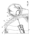
- FIG. 24 illustrates the view in FIG. 23 from a different point of view
- FIG. 25 illustrates a perspective view and from the interior of the stomach of a further step of the method
- FIG. 26 illustrates the view in FIG. 25 from a different point of view
- FIG. 27 illustrates a perspective view and from the interior of the stomach of a further step of the method
- FIG. 28 illustrates a perspective, enlarged and partially phantom view of a detail of the portion of FIG. 1 at the end of a third sequence of steps of the method
- FIG. 29 illustrates a perspective view of the portion of FIG. 1 at the end of the third sequence of steps of the method
- FIG. 30 illustrates a perspective and exploded view of an anastomotic device suitable for being used in some steps of the method
- FIG. 31 illustrates a perspective and enlarged view of a detail of an insertion device suitable for being used in some steps of the method
- FIG. 32 illustrates a perspective view of a positioning device according to the present invention suitable for being used in some steps of the method
- FIG. 33 illustrates a perspective view of the positioning device of FIG. 32 according to a different point of view and associated to a variant embodiment of a portion of the anastomotic device of FIG. 30 ;
- FIG. 34 illustrates a perspective view of a step of the method, carried out with a variant embodiment of the anastomotic device illustrated in FIG. 30 ;
- FIGS. 35 and 36 illustrate two corresponding steps of a possible embodiment of a method for performing anastomoses in tracts of the digestive tube
- FIG. 37 illustrates a possible variant embodiment of an anastomotic device
- FIG. 38 illustrates a possible further variant embodiment of an anastomotic device.
- the positioning device is suitable for deploying at least one locking portion 20 of an anastomotic device 10 for approximating a first tissue portion 12 and a second tissue portion 14 to be connected by means of anastomosis.
- An exemplary embodiment of the anastomotic device will be described below.
- the positioning device is suitable to exert a thrust on the locking portion 20 in order to snap-connect the latter to an abutment portion 18 of the anastomotic device 10 which is placed opposite the first and second tissue portions.
- the positioning device is advantageously suitable to slide along a guide means comprising at least one guide wire A, B and comprises an elongated structure 50 .
- the positioning device comprises a head 52 suitable to be interference-fitted on a distal end of the elongated structure 50 .
- the head 52 is suitable to abut against a portion of the anastomotic device.
- the head 52 comprises elastic tabs 54 which extend from a proximal end of the same head in order to insert and hold the head onto the elongated structure.
- the head 52 comprises at least one channel 56 suitable for receiving a guide wire, such that the aforesaid positioning device is advantageously suitable for sliding along said guide means.
- the head 52 comprises two channels 56 which are suitable for receiving a guide wire, respectively.
- the channels 56 are placed on opposite sides of the head 52 .
- the head 52 comprises a distal end defining a thrust surface 58 for a locking portion 20 of the anastomotic device 10 .
- the distal end is counter-shaped relative to the locking portion 20 of the anastomotic device 10 .
- the distal end of the head 52 comprises at least one opening 60 for receiving said elastic tabs 28 .
- the elongated structure is a visualization device, such as a gastroscope.
- the head 52 can be applied both to a flexible structure and a rigid structure.
- the locking portion 20 is suitable for sliding along a guide means comprising at least one guide wire A, B and has an interaction portion with the positioning device 48 which pushes the latter along the guide wire A, B.
- the positioning device allows adapting previously existing structures, such as visualization devices (gastroscopes), in particular to the purpose of carrying out an endoluminal technique to perform anastomosis of tracts of the digestive tube.
- visualization devices such as gastroscopes
- the elongated structure can however be done both via a flexible structure, and via a rigid structure, in order to exert a higher bias on the anastomotic device, and via a “stiffening” structure, i.e. a flexible structure suitable for becoming rigid.
- the positioning device according to the present invention is easy and efficient and, by being able to slide on guide wires, it allows for a correct positioning of the two portions of the anastomotic device.
- FIG. 30 With reference to FIG. 30 , with 10 has been generally designated an anastomotic device according to a possible embodiment.
- FIGS. 18-28 , 33 and 34 illustrate possible applications of the anastomotic device 10 or variant embodiments thereof.
- the anastomotic device is suitable for approximating and keeping close to each other a first tissue portion 12 and a second tissue portion 14 that are intended to form an anastomosis 16 .
- the anastomotic device 10 is suitable for being used in a method, preferably endoluminally, for performing anastomoses in tracts of the digestive system.
- it can be optionally used in partially or wholly laparoscopic techniques or conventional surgical techniques.
- FIG. 30 illustrates an exploded view of a preferred embodiment of the anastomotic device 10 in which an abutment portion has been designated with 18 and a locking portion has been designated with 20 .
- the abutment portion 18 can also be defined as the intestinal portion, while the locking portion 20 can also be defined as the gastric portion.
- the abutment portion 18 is suitable for abutting against a surface of the first tissue portion 12
- the locking portion 20 is adapted to be arranged opposite the abutment portion 18 with respect to the first tissue portion 12 and to the second tissue portion 14 .
- the locking portion 20 and the abutment portion 18 are mutually connectable or couplable across the first and second tissue portions being drawn together, in order to keep them joined to each other. More particularly, the locking portion 20 and the abutment portion 18 are suitable for being mutually locked in at least two locking positions corresponding to different compression degrees of the first and second tissue portions.
- the abutment portion 18 comprises at least one pin 22 suitable for passing through the first tissue portion 12 and the second tissue portion 14 and to enter a housing 24 of the locking portion 20 in order to fit thereto.
- the pin is adapted to snap fit and lock within the housing 24 of the locking portion 20 .
- the snap fit is for example carried out by means of a pin 22 provided with at least one shaped portion 26 suitable for defining a snap connection with elastic tabs 28 that are associated to the respective housing 24 of the locking portion 20 .
- the elastic tabs 28 extend in the direction of the respective pin 22 away from the abutment portion 18 to extend the housing 24 .
- the shaped portion 26 is provided by means of a sequence of ring ribs 30 . Furthermore, a free end of the pin 22 is shaped so as to promote the snap fitting, for example providing an outwardly tapering or frusto-conical end 32 . Furthermore, the elastic tabs 28 are distributed along a peripheral edge of the respective housing 24 and extend in the direction and sense of insertion of the pin 22 .
- the pin 22 is movably mounted, preferably screwed, to the abutment portion 18 .
- the pin 22 defines internally a channel 34 that is opened on both sides and preferably adapted to receive a guide wire, as it will be described herein below.
- the respective housing 24 is adapted to receive the guide wire passing through the channel 34 .
- the anastomotic device 10 comprises two pins 22 , as described above, which extend from the abutment portion 18 and are adapted to be inserted in respective housings 24 of the locking portion.
- the pins are located at opposite areas or sides of the abutment portion 18 and, similarly, the housings adapted to receive the pins are located at opposite areas or sides of the locking portion 20 .
- each pin defines a channel 34 therein, which is adapted to receive a respective guide wire.
- each pin defines a channel 34 therein to receive a respective guide wire.
- the locking portion 20 presents an opening 36 to access the area intended for the formation of the anastomosis.
- these are located at opposite parts or sides of the opening 36 .
- the locking portion 20 is substantially ring-shaped.
- the abutment portion 18 has an opening 38 to access the area intended for the formation of the anastomosis and corresponding to the opening 36 of the locking portion.
- these are preferably located at opposite parts or sides of the opening 38 .
- the abutment portion 18 is, preferably, substantially ring-shaped.
- a contact surface of the locking portion 20 suitable for the abutment against a surface of the second tissue portion 14 to approximate has been indicated with 40 .
- This contact surface is a surface opposite to the extension of the elastic tabs 28 , when provided.
- the contact surface 40 is rough or presents pointed members 42 ( FIGS. 33 and 34 ).
- annular grooves 43 a can be provided ( FIG. 37 ) or, the roughness can be imparted through a layer 43 b made of reported material for example in granular form ( FIG. 38 ).
- a contact surface of the abutment portion 18 suitable for the abutment against a surface of the first tissue portion 12 to be approximated has been indicated with 44 .
- this contact surface is a surface located on the same side as the at least one pin 22 .
- the contact surface 44 is rough or presents pointed members 46 ( FIG. 34 ).
- annular grooves 43 a can be provided ( FIG. 37 ) or, the roughness can be imparted through a layer 43 b made of material reported for example in granular form ( FIG. 38 ).
- the anastomotic device 10 is a device suitable for approximating and keeping close to each other a first tissue portion and a second tissue portion that are intended to form an anastomosis, which can be connected to a guide means, for example a guide wire or, preferably, at least two guide wires to reach the tissue portions, as it will be described below.
- a guide means for example a guide wire or, preferably, at least two guide wires to reach the tissue portions, as it will be described below.
- At least one of the abutment portion 18 and the locking portion 20 is suitable for being connected to a guide means comprising at least one guide wire to reach the first or second tissue portions.
- the abutment portion 18 is suitable for being locked in a direction on the guide means, for example the guide wires A and B, which are preferably located on two opposite sides of the anastomotic device, through which it is dragged until reaching the first tissue portion 12 .
- the abutment portion 18 is fastened to the guide wires such as to be dragged by the latter at the first tissue portion to draw the two tissue portions together, thus allowing the guide wires to be then taken off in the opposite direction.
- the abutment portion 18 is suitable for being locked on the guide wires A, B for example by means of locking members 61 made integral to a guide wire, respectively, and suitable for defining an obstacle for the sliding movement of the abutment portion 18 in a direction on the guide wires ( FIG. 17 ).
- the abutment portion 18 comprises at least one channel suitable for receiving a guide wire.
- two guide wires are provided, two channels located on opposite sides of the anastomotic device are advantageously provided. Furthermore, it is advantageously provided that the channels pass through the abutment portion 18 .
- the guide means pass through the abutment portion 18 and the locking portion 20 at connecting members between the two portions.
- the anastomotic device 10 comprises at least one pin in order to be connected to the locking portion 20
- this pin 22 defines a channel 34 suitable for receiving a guide wire.
- the anastomotic device 10 comprises at least two pins 22 to be connected to the locking portion
- the two pins 22 define a channel 34 adapted to receive a guide wire, respectively.
- the locking portion 20 is adapted to slide along the guide means and presents an interacting portion with said positioning device 48 which biases the latter along said guide means.
- the pins 22 can be made as one piece with the abutment portion 18 .
- the pins can extend from the locking portion 20 and be inserted in housings of the abutment portion 18 .
- the anastomotic device 10 can be made of any type of material suitable for surgical applications.
- both the abutment portion and the locking portion can be made in not-bioabsorbable material, for example in plastic or metallic material.
- the anastomotic device 10 spontaneously detaches and moves away when the tissue to which it is attached necrotizes.
- the anastomotic device can be made such as to stay in a steady position.
- the choice of the material can be directed towards a bioabsorbable or biofragmentable material, thus providing that the anastomotic device is completely absorbed after a preset period of time.
- the anastomotic device 10 can be partially made of bio-absorbable or biofragmentable material.
- the connecting members between the abutment portion and the locking portion are made of bioabsorbable or biofragmentable material, in order to allow the anastomotic device to disengage from the site to which it has been applied after a preset period of time and to spontaneously move away.
- the pins 22 and/or the housings 24 and/or the elastic tabs 28 are made in bioabsorbable or biofragmentable material.
- An anastomotic device 10 suitable for approximating and keeping close to each other a first tissue portion 12 and a second tissue portion 14 that are intended to form an anastomosis 16 can generally be made in such a way that the abutment portion and the locking portion are mutually connectable across the first and second tissue portions drawn together in order to keep them joined to each other.
- an individual pin 22 can be provided and optionally different from the housing channel of the guide wire.
- this anastomotic device can be inserted and locked even on an individual guide wire or on more than two guide wires.
- the application example relates to a method for performing anastomoses in tracts of the digestive tube, and in particular to a method for endoluminally performing a gastrojejunostomy, for example as illustrated in FIGS. 18-28 .
- Other applications are possible, such as a jejuno-jejunostomy, generally an entero-enteroanastomosis or other kinds of anastomosis.
- FIG. 18 a portion of the digestive system comprising stomach and an intestine tract, corresponding to a jejune tract is illustrated.
- a guide means for example comprising two guide wires has been located starting from a natural orifice, such as the oesophagus, and forms an open ring or loop which passes through the first tissue portion 12 and the second tissue portion 14 .
- the two guide wires A and B extend between proximal end portions A′ and B′ and distal end portions A′′ and B′′.
- the abutment portion 18 of the anastomotic device 10 is inserted on proximal end portions of the guide wires and locked, for example by means of locking members 61 that are firmly connected or made integral to a guide wire, respectively, and suitable for defining an obstacle to the sliding of the abutment portion 18 on said guide wires ( FIG. 17 ).
- other locking means can be provided, for example integrated in the anastomotic device structure.
- the abutment portion 18 is pre-connected or integral to the guide wires in such a way that when the distal ends of the guide wires are dragged, the abutment portion is dragged and drawn against the tissue portions to be connected.
- the abutment portion 18 is subsequently drawn together to the first tissue portion 12 by pulling distal end portions of the guide wires ( FIG. 19 ) until the pins 22 are inserted into and pass through the first tissue portion 12 ( FIG. 20 ).
- FIGS. 18-21 illustrate an application of an anastomotic device 10 , i.e. an anastomotic device suitable for approximating a first tissue portion and a second tissue portion that are intended to form an anastomosis.
- the anastomotic device 10 can be used not only to draw together but also to keep close the two tissue portions to each other.
- FIGS. 22-28 This application is further illustrated in FIGS. 22-28 , in which the application of the locking portion 20 is shown, preferably biased in position along the guide wires by the positioning device 48 .
- the locking portion 20 is inserted on the distal end portions A′′ and B′′ of the guide wires through the housings 24 .
- the head 52 is also subsequently inserted on the distal end portions of the guide wires through the channels 56 .
- the head 52 is fitted on the distal end of the elongated structure 50 , or gastroscope ( FIG. 22 ).
- the positioning device 48 interacts with the locking portion 20 via the thrust surface 58 and the elastic tabs 28 are inserted in the respective openings 60 .
- the head 52 biases the locking portion 20 in position by sliding on the guide wires until approaching to the second tissue portion 14 , oppositely of the abutment portion 18 , i.e. on the stomach side ( FIGS. 23 and 24 ).
- the pins 22 are inserted in the housings 24 of the locking portion and the frusto-conical end 32 enlarges the elastic tabs 28 , which abut between a ring rib 30 and the next one, thus providing a snap fit ( FIGS. 25 and 26 ).
- the bias exerted on the locking portion 20 via the head 52 and the elongated structure 50 allows selecting one of the possible mutual positions of the abutment portion 18 and the locking portion 20 .
- ring ribs 30 allows to define at least two relative positions between the abutment portion 28 and the locking portion 20 , in order to set an optimum compression degree of the tissues, which can be assessed as a function of their more or less ischemic coloration.
- the locking portion 20 remains attached to the abutment portion 18 allowing to keep the two tissue portions ( FIGS. 27 and 28 ) joined to each other. Subsequently, the anastomosis can be completed as will be described below.
- an anastomotic device as described above allows to provide an efficient and user-friendly tool, and moreover a tool suitable for performing endoluminally anastomoses of tracts of the digestive tube, even if its use is possible also in other techniques, for example partially or wholly laparoscopic techniques or conventional surgical techniques.
- a first object of the device is to provide an abutment portion which allows two tissue portions to be approximated, which are to be connected by anastomosis.
- this device can be connected, or even locked, on at least two guide wires, it allows to control and direct the anastomotic device throughout the path within the digestive system, both to draw together and connect the two tissue portions.
- the latter aspect may be independent of the presence of one or more guide wires, even if the combination of the two aspects allows to accurately control and direct also the locking step, in particular in the case where the guide wires pass through the pins and the connecting housings between the two portions. As a consequence, it a very compact anastomotic device is further achieved.
- a method is described below for performing anastomosis in tracts of the digestive tube in which a positioning device is used such as described above.
- This method generally comprises the steps of:
- At least one guide wire (A, B) extending between proximal end portions (A′, B′) and distal end portions (A′′, B′′) and passing through a first tissue portion ( 12 ) and a second tissue portion ( 14 ) in which the anastomosis has to be performed,
- the positioning device is suitable for sliding along said at least one guide wire.
- the guide means comprises at least two guide wires A, B placed side by side, and the positioning device is suitable for sliding along said at least two guide wires.
- the guide wires are arranged to form a loop with end portions at natural orifices or other orifices.
- the loop passes through the first tissue portion 12 and the second tissue portion 14 to be connected, and the anastomotic device 10 is inserted on the ring-shaped guide wires A and B.
- a method for performing a gastro-jejunoanastomosis has been illustrated, in which a positioning device and an anastomotic device 10 are used. It should be understood that further and different uses are possible, for example in a method for performing generally entero-enteroanastomosis or, more particularly, jejuno-jejunoanastomosia or ileo-jejunanastomosis
- a first step of the aforesaid method provides for the introduction, through a natural orifice or other luminal structures, of at least two guide wires A and B placed beside, for example substantially parallel, to each other.
- the guide wires extend between proximal end portions A′ and B′ and distal end portions A′′ and B′′ and pass through a first tissue portion 12 and a second tissue portion 14 where the anastomosis is to be performed.
- the guide wires can be introduced such as to remain at least partially placed side by side at a determined distance from each other or placed side by side and drawn together.
- the guide wires are spaced apart from each other both during the introduction step and during the step of passing through the first tissue portion to be connected by means of anastomosis.
- the guide wires are drawn together and placed side by side also during the introduction and the passing-through step of the first tissue portion. In the latter case, they can also be connected at the distal end to be subsequently separated when the insertion has been completed.
- the aforesaid method provides the insertion of an anastomotic device along the two guide wires and dragging it to the anastomotic site, by drawing the first tissue portion and the second tissue portion together and performing an anastomosis.
- the abutment portion 18 is pre-connected to the guide wires in such a way that when the distal ends of the guide wires are dragged, the abutment portion is dragged and drawn to the tissue portions to be connected.
- the two guide wires are located so as to form a loop with the end portions at natural orifices, or other orifices, while the loop passes through the first tissue portion 12 and the second tissue portion 14 to be connected.
- the anastomotic device is inserted along the two loop-shaped wires to perform the anastomosis, preferably endoluminally.
- the distal ends of the two guide wires are first inserted to the first tissue portion 12 and introduced therethrough until they pass therethrough and project oppositely.
- the two guide wires are inserted by means of an insertion device 62 at least until they reach and pass through the first tissue portion 12 .
- the insertion device 62 comprises an elongated structure that is preferably provided by means of a visualization device, for example, a gastroscope 64 , provided with a first operative channel 66 suitable for receiving and inserting one of the guide wires.
- a connecting head 68 suitable for being mounted to a distal end of the elongated structure (visualization device 64 ) can be further provided.
- the connecting head 68 is integral with at least one second operative channel 70 suitable for receiving and inserting another guide wire of said guide wires.
- the operative channel 70 extends substantially throughout the length of the elongated structure to keep the two guide wires distinct during the insertion.
- the second operative channel 70 is located externally to the elongated structure, made integral with the latter by means of the connecting head 68 .
- first and second operative channels are suitable for displacing a guide wire, respectively, in a method for performing anastomoses in tracts of the digestive tube.
- the operative channels are located at a determined distance from each other, so as to keep the guide wires apart when they are inserted and passed through the first tissue portion.
- the second operative channel 70 is located opposite the visualization device 64 relative to the first operative channel 66 .
- the connecting head 68 is suitable for being interference-fitted on a distal end of the visualization device 64 .
- the connecting head 68 comprises elastic tabs 72 which extend from a proximal end of the head.
- the insertion device has an individual operative channel in order to insert the guide wires simultaneously and placed beside one to the other.
- the guide wires pass through the first tissue portion at a same opening.
- the two guide wires can be originally connected to each other at the distal end and, subsequently, separated at the end of their insertion.
- the insertion device 62 is assembled externally to the patient, by inserting the connecting head 68 on the distal end of the elongated structure (visualization device 64 — FIG. 31 ). Subsequently, the insertion device 62 is introduced in the oesophagus and in the stomach ( FIG. 2 ) to the jejune and the first tissue portion 12 ( FIG. 3 ).
- a guide wire A is inserted through the first operative channel 66 until a distal end of the guide wire projects from the distal end of the insertion device 62 ( FIG. 4 ) and passes through the wall of the first tissue portion.
- a distal end portion A′′ of the guide wire extends beyond the wall of the first tissue portion.
- a second guide wire is inserted through the second operative channel 70 until a distal end of the guide wire projects from the distal end of the insertion device 62 ( FIG. 5 ) and passes through the wall of the first tissue portion.
- a distal end portion B′′ of the second guide wire extends beyond the wall of the first tissue portion ( FIG. 6 ). The insertion device is then withdrawn ( FIG. 7 ).
- the first tissue portion wall is punched for example by means of radiofrequency or via other devices, optionally introduced by means of the same insertion device 62 .
- a sheath 63 containing a radiofrequency needle is inserted along the first operative channel 66 to the first tissue portion wall.
- the radiofrequency needle punches the wall, and subsequently a guide wire A is inserted along the sheath 63 until passing through the first tissue portion wall, at the hole made by the radiofrequency needle.
- the same procedure can be followed when the guide wire B is positioned through the second operative channel 70 .
- the guide wires when the guide wires are inserted, they are drawn together and placed beside one to the other through only one individual operative channel, for example of an insertion device or of a visualization device.
- the first tissue portion wall is punched in an individual point, for example by means of radiofrequency or through other devices, optionally introduced by means of the same insertion device.
- the first tissue portion substantially corresponds to a tract of the jejune, and the guide wires pass therethrough after a jejunostomy has been performed.
- a step is provided of separating and identifying the proximal end portions A′ and B′ of the guide wires coming out of the luminal structure.
- the step of separating and identifying the proximal end portions of the guide wires coming out of the luminal structure is performed by introducing a first sheath 74 on the two guide wires starting from a proximal end of the guide wires.
- the first sheath has a characterizing element, for example it is made in a certain colour ( FIG. 8 ).
- a grasping device 76 through the second tissue portion 14 to be connected in order to grasp the distal end portions A′′ and B′′ of the two guide wires is advantageously provided.
- the creation of a hole 78 is advantageously provided in the second tissue portion 14 , for example by means of a radiofrequency needle or the like.
- the hole 78 is optionally enlarged by a balloon catheter 80 , preferably introduced via an operative channel of the grasping device ( FIGS. 10 and 11 ).
- the grasping device comprises a visualization device, for example of the gastroscopic kind, in which an operative channel is used to insert the balloon catheter 80 and subsequently a snare 82 for grasping the distal end portions A′′ and B′′ of the guide wires.
- the grasping device 76 passes through the hole 78 and reaches the distal ends of the guide wires ( FIG. 12 ).
- the snare closes on the distal end portions of the guide wires ( FIG. 13 )
- the snare, together with the grasping device is retracted through the hole 78 ( FIG. 14 ) to the orifice through which it had been introduced.
- the guide wires are then located to form a loop with distal and proximal end portions preferably brought back in the same orifice ( FIG. 15 ).
- the grasping device can be activated in a wholly endoluminal way, or through laparoscopic supervision.
- the hole 78 gastrostomy
- the surgeon laparoscopically individuates the distal end portions A′′ and B′′ and inserts them into the snare, under laparoscopic control.
- the snare is closed again and dragged back so as to form the loop, as provided in FIG. 15 .
- a step is provided of separating and identifying the distal end portions of the guide wires that come out of the luminal structure after they have passed through the first and second tissue portions.
- this step of separating and identifying the distal end portions of the guide wires is performed by introducing a second sheath 84 on the two guide wires starting from the distal end of the guide wires.
- the second sheath has a characterizing feature, for example a colour other than that of the first sheath 74 ( FIG. 16 ).
- the anastomotic device is inserted on the two guide wires so as to draw and optionally keep drawn the first tissue portion and the second tissue portion together, as described above.
- the abutment portion 18 is pre-associated or integral to the guide wires in such a way that when the distal ends of the guide wires are dragged, the abutment portion is dragged and drawn together to the tissue portions to be connected.
- the abutment portion 18 of the anastomotic device 10 is inserted on the proximal end portions of the guide wires after removing the first sheath 74 which, when the abutment portion of the anastomotic device has drawn the two tissue portions to be connected together, is preferably repositioned on the proximal end portions of the guide wires.
- the locking portion 20 of the anastomotic device 10 is subsequently inserted on the distal end portions A′′ and B′′ of the guide wires after removing the second sheath 84 .
- the final step of the method provides for the completion of the anastomosis.
- the anastomosis is performed at the opening of the two annular structures of the anastomotic device.
- the anastomosis is performed on the side of the jejune, by introducing for example a radiofrequency needle suitable for punching the wall.
- a balloon catheter is then introduced to enlarge the punching and/or a further tool to remove a part of the tissue.
- the anastomosis can be performed on the side of the stomach. In this case, it is possible to provide the introduction of a shielding device in the jejune, in order to avoid that the punching also affects the jejune wall opposite to that in which the anastomosis has to be performed.
- the guide means are removed, for example by pulling the proximal end portions A′ and B′, as in the case where the locking members 61 are provided.
- the guide wires are pulled in the direction in which they can slide relative to the anastomotic device.
- a seal test of the anastomosis based on methylene blue can be provided.
- FIG. 1 illustrates a portion of the digestive apparatus comprising the oesophagus, the stomach and a tract of the intestine corresponding to the jejune.
- the two guide wires A and B are introduced through the oesophagus, which is a natural orifice, or through another orifice, also artificial, until reaching the stomach and a tract of the jejune ( FIG. 7 ).
- the two guide wires A and B are loop-shaped with distal A′′, B′′ and proximal end portions A′, B′ debouching through the aforesaid orifice ( FIG. 15 ).
- the loop passes through the portions to be connected, respectively a jejunectomy and a gastrostomy.
- the two guide wires A and B are introduced through the oesophagus, the stomach and a tract of the jejune and one distal end thereof is passed through the jejune wall corresponding to the first tissue portion to be connected ( FIG. 6 ), for example after punching this wall by means of radiofrequency needles as described above.
- This step is performed preferably via an insertion device 62 as illustrated in FIGS. 2-6 , as described above.
- the guide wires are inserted by being drawn together and placed beside one to the other through a single operative channel, for example of an insertion device or of a visualization device.
- the first tissue portion wall is punched in an individual point, for example by means of radiofrequency or through other devices, optionally introduced by means of the same insertion device.
- the method may be optionally performed also using an individual guide wire when using an anastomotic device suitable to the purpose.
- the aforesaid method allows a continuous control both in the step of positioning the guide wires and in the step of drawing together and connecting the tissue portions.
- the steps provided herein further allow an endoluminal approach for procedures until now applied in the conventional surgery or laparoscopically, even if laparoscopic or partially laparoscopic techniques are not excluded.
- the above-described method can be further used to perform different kinds of anastomoses, for example a jejuno-jejunoanastomosis, particularly in order to achieve a gastro-intestinal by-pass, or a colon-colon anastomosis with transanal access.
- anastomoses for example a jejuno-jejunoanastomosis, particularly in order to achieve a gastro-intestinal by-pass, or a colon-colon anastomosis with transanal access.
- the aforesaid method to perform anastomosis in tracts of the digestive tube can be applied in the case illustrated in FIGS. 35 and 36 , in particular to obtain a gastro-intestinal by-pass.
- This method comprises steps of drawing-together and connecting the tissues 12 , 14 to form anastomoses 88 , 94 suitable for keeping or reintegrating the integrity and the continuity of the intestinal duct after each formation of an anastomosis (both the gastro-jejuno anastomosis and the jejuno-jejuno anastomosis).
- the gastro-jejuno anastomosis and the jejuno-jejuno anastomosis are performed at a closed-up distance, thus allowing for a wide operative and visual field, while remaining only in the upper area of the abdomen.
- the steps of bringing tissues together and creating the gastro-jejunoanastomosis and/or the jejuno-jejunoanastomosis can be performed using a guide means comprising preferably at least two guide wires that are placed side by side and located to form a loop which passes through the tissue portions to be connected.
- the guide means can be associated to an anastomotic device according to the present invention or other anastomotic or positioning devices.
- the aforesaid method can be performed endoluminally, or in a partially or wholly laparoscopic way.
- the partial creation of a pocket 100 into the stomach can be preventively provided, to which the first portion of the jejune will be connected.
- a first guide wire loop is made through the open portion of the gastric pocket and through the portions of the jejune and the stomach to be connected.
- An anastomotic device is inserted and locked on the guide means and dragged, by the guide means, until abutting against the first portion to be connected and drawing it together with the second portion to be connected.
- This first sequence of steps ends by carrying out a gastro-jejunoanastomosis 88 and forming a first intestine loop 86 .
- a guide wire second loop is made through the open portion of the gastric pocket and through the two portions of the jejune to be connected.
- an anastomotic device is inserted and locked in a direction on the guide means and dragged, by means of the same guide means, until abutting against the first portion to be connected and drawing it together with the second portion to be connected.
- This second sequence of steps ends by performing an entero-enteroanastomosis 94 , carrying out a second ring 96 of intestine and completing the gastric pocket 100 .
- a section line of the intestine between the two anastomoses has been designated with 98 .
- the passing of the guide means through the walls of the tissues to be connected can be performed by punching the wall (for example with radiofrequency needles) at the area intended to form the anastomosis, so as that after the formation of the anastomosis, the continuity of the intestinal duct is reintegrated.
- An anastomotic device suitable to the purpose can be that described in the present application, or anastomotic or positioning devices suitable for releasing an anastomotic ring to perform the anastomosis, or a circular stapler sliding on the guide means and cooperating with an anvil, also sliding on the guide means.
- the guide means and the anastomotic device can be spaced apart from each other and suitable for being mutually associated upon use.
- a guide means can be provided in which the anastomotic device (and particularly the abutment portion 18 ) is pre-assembled or integrated on the guide means, so as it can be dragged in a direction and taken off in the opposite direction or be taken off together with the guide wires.
- the guide wires can be at least partially placed side by side at a certain distance from each other, or placed beside and drawn together.
- the guide wires can be introduced by means of a same operative channel, placed side by side and drawn together, so as to pass through the first tissue portion at a common opening.
- the distal ends of the guide wires can be mutually connected. They will be optionally separated after the loop has been made.
- this method allows to reduce the mortality risks in the case of gastro-intestinal by-passes and to considerably minimize the intervention times.
- the preservation of the continuity of the intestine until the completion of the two anastomoses allows for the simultaneous assessment of both. Furthermore, by virtue of the close arrangement of the two anastomoses, the surgical field is restricted to the upper area of the abdomen.
Abstract
Description
-
- inserting a locking
portion 20 of saidanastomotic device 10 on the distal end portion A″, B″ of said at least one guide wire on the opposite side of theabutment portion 18 relative to the first and second tissue portions, - pushing said locking
portion 20 along said at least one guide wire by means of a positioning device as described above, until it is coupled with connecting elements of theabutment portion 18, which pass through the first and second tissue portions, - completing the anastomosis at
openings abutment portion 18 and lockingportion 20.
- inserting a locking
Claims (6)
Applications Claiming Priority (4)
| Application Number | Priority Date | Filing Date | Title |
|---|---|---|---|
| IT000060A ITMI20060060A1 (en) | 2006-01-16 | 2006-01-16 | PR POSITIONING DEVICE DEPLOY AT LEAST ONE BLOCKING PORTION OF AN ANASTOMOTIC DEVICE AND THE PEER METHOD PERFORM ANASTOMOSIS IN THE DIGESTIVE TUBE |
| ITMI2006A000060 | 2006-01-16 | ||
| ITMI2006A0060 | 2006-01-16 | ||
| PCT/EP2007/000196 WO2007080112A1 (en) | 2006-01-16 | 2007-01-11 | Positioning device for deploying at least one locking portion of an anastomotic device and method for carrying out anastomosis in tracts of the digestive tube |
Publications (2)
| Publication Number | Publication Date |
|---|---|
| US20100069933A1 US20100069933A1 (en) | 2010-03-18 |
| US8435231B2 true US8435231B2 (en) | 2013-05-07 |
Family
ID=37969565
Family Applications (1)
| Application Number | Title | Priority Date | Filing Date |
|---|---|---|---|
| US12/159,003 Expired - Fee Related US8435231B2 (en) | 2006-01-16 | 2007-01-11 | Positioning device for deploying at least one locking portion of an anastomotic device and method for carrying out anastomosis in tracts of the digestive tube |
Country Status (8)
| Country | Link |
|---|---|
| US (1) | US8435231B2 (en) |
| EP (1) | EP1973478B1 (en) |
| JP (1) | JP2009523477A (en) |
| CN (1) | CN101374468B (en) |
| AT (1) | ATE465681T1 (en) |
| DE (1) | DE602007006155D1 (en) |
| IT (1) | ITMI20060060A1 (en) |
| WO (1) | WO2007080112A1 (en) |
Families Citing this family (7)
| Publication number | Priority date | Publication date | Assignee | Title |
|---|---|---|---|---|
| BRPI0709278A2 (en) * | 2006-03-25 | 2011-07-12 | Aponos Medical Corp | tissue securing device, method for endoscopically attaching tissue using a fastener and combination of tissue fastener and dispensing device for said fastener |
| EP3456238B1 (en) | 2008-11-18 | 2020-05-13 | United States Endoscopy Group, Inc. | Method of attaching devices to endoscopes using an adapter |
| WO2013004263A1 (en) * | 2011-07-01 | 2013-01-10 | Ethicon Endo-Surgery, Inc. | A connecting device for creating an anastomosis between a hollow organ and a conduit |
| CN105031798A (en) * | 2015-08-06 | 2015-11-11 | 成都迅德科技有限公司 | Medical positioning apparatus |
| CN107296992B (en) * | 2017-06-13 | 2019-09-13 | 中国人民解放军总医院第一附属医院 | Blood vessel docking facilities and Vascular injury including the device give treatment to device |
| CN107536631B (en) * | 2017-08-24 | 2020-01-17 | 王培吉 | Micro-vessel anastomat |
| WO2019217851A1 (en) * | 2018-05-11 | 2019-11-14 | Mayo Foundation For Medical Education And Research | Luminal apposition devices |
Citations (3)
| Publication number | Priority date | Publication date | Assignee | Title |
|---|---|---|---|---|
| US20010016749A1 (en) | 1999-04-16 | 2001-08-23 | Blatter Duane D. | Externally directed anastomosis systems and externally positioned anastomosis fenestra cutting apparatus |
| US20040097994A1 (en) | 1999-04-16 | 2004-05-20 | Blatter Duane D. | Staple and anvil anastomosis system |
| US20050216043A1 (en) | 2004-03-26 | 2005-09-29 | Blatter Duane D | Stented end graft vessel device for anastomosis and related methods for percutaneous placement |
Family Cites Families (9)
| Publication number | Priority date | Publication date | Assignee | Title |
|---|---|---|---|---|
| US4873977A (en) * | 1987-02-11 | 1989-10-17 | Odis L. Avant | Stapling method and apparatus for vesicle-urethral re-anastomosis following retropubic prostatectomy and other tubular anastomosis |
| US5035702A (en) * | 1990-06-18 | 1991-07-30 | Taheri Syde A | Method and apparatus for providing an anastomosis |
| GR1002290B (en) * | 1991-06-03 | 1996-05-02 | Ethicon Inc. | Absorbable anastomosic fastener means. |
| US5197649A (en) * | 1991-10-29 | 1993-03-30 | The Trustees Of Columbia University In The City Of New York | Gastrointestinal endoscoptic stapler |
| JPH0647050A (en) * | 1992-06-04 | 1994-02-22 | Olympus Optical Co Ltd | Tissue suture and ligature device |
| US6569173B1 (en) * | 1999-12-14 | 2003-05-27 | Integrated Vascular Interventional Technologies, L.C. | Compression plate anastomosis apparatus |
| US6543456B1 (en) * | 2002-05-31 | 2003-04-08 | Ethicon Endo-Surgery, Inc. | Method for minimally invasive surgery in the digestive system |
| JP2004147969A (en) * | 2002-10-31 | 2004-05-27 | Univ Waseda | Device and implement for anastomosis |
| US7618427B2 (en) * | 2003-12-29 | 2009-11-17 | Ethicon Endo-Surgery, Inc. | Device and method for intralumenal anastomosis |
-
2006
- 2006-01-16 IT IT000060A patent/ITMI20060060A1/en unknown
-
2007
- 2007-01-11 EP EP07702681A patent/EP1973478B1/en active Active
- 2007-01-11 JP JP2008549829A patent/JP2009523477A/en active Pending
- 2007-01-11 AT AT07702681T patent/ATE465681T1/en not_active IP Right Cessation
- 2007-01-11 CN CN2007800031883A patent/CN101374468B/en not_active Expired - Fee Related
- 2007-01-11 WO PCT/EP2007/000196 patent/WO2007080112A1/en active Application Filing
- 2007-01-11 DE DE602007006155T patent/DE602007006155D1/en active Active
- 2007-01-11 US US12/159,003 patent/US8435231B2/en not_active Expired - Fee Related
Patent Citations (3)
| Publication number | Priority date | Publication date | Assignee | Title |
|---|---|---|---|---|
| US20010016749A1 (en) | 1999-04-16 | 2001-08-23 | Blatter Duane D. | Externally directed anastomosis systems and externally positioned anastomosis fenestra cutting apparatus |
| US20040097994A1 (en) | 1999-04-16 | 2004-05-20 | Blatter Duane D. | Staple and anvil anastomosis system |
| US20050216043A1 (en) | 2004-03-26 | 2005-09-29 | Blatter Duane D | Stented end graft vessel device for anastomosis and related methods for percutaneous placement |
Also Published As
| Publication number | Publication date |
|---|---|
| EP1973478A1 (en) | 2008-10-01 |
| WO2007080112A1 (en) | 2007-07-19 |
| ITMI20060060A1 (en) | 2007-07-17 |
| ATE465681T1 (en) | 2010-05-15 |
| US20100069933A1 (en) | 2010-03-18 |
| CN101374468B (en) | 2010-09-29 |
| DE602007006155D1 (en) | 2010-06-10 |
| JP2009523477A (en) | 2009-06-25 |
| CN101374468A (en) | 2009-02-25 |
| EP1973478B1 (en) | 2010-04-28 |
Similar Documents
| Publication | Publication Date | Title |
|---|---|---|
| US8006701B2 (en) | Device and method for the therapy of obesity | |
| US8845661B2 (en) | Device and method for the therapy of obesity | |
| US8435231B2 (en) | Positioning device for deploying at least one locking portion of an anastomotic device and method for carrying out anastomosis in tracts of the digestive tube | |
| US8187289B2 (en) | Device and method for the therapy of obesity | |
| US8540739B2 (en) | Anastomotic device | |
| EP1908421B1 (en) | A carrier member, anastomotic device and instrumentation for performing endoluminal and/or transluminal anastomosis | |
| EP1973477B1 (en) | Equipment to approximate tissue portions, which are intented to form an anastomosis |
Legal Events
| Date | Code | Title | Description |
|---|---|---|---|
| AS | Assignment |
Owner name: ETHICON ENDO-SURGERY, INC.,OHIO Free format text: ASSIGNMENT OF ASSIGNORS INTEREST;ASSIGNORS:D'ARCANGELO, MICHELE;KUHNS, JESSE J.;PASTORELLI, ALESSANDRO;AND OTHERS;SIGNING DATES FROM 20080715 TO 20080724;REEL/FRAME:021775/0902 Owner name: ETHICON ENDO-SURGERY, INC., OHIO Free format text: ASSIGNMENT OF ASSIGNORS INTEREST;ASSIGNORS:D'ARCANGELO, MICHELE;KUHNS, JESSE J.;PASTORELLI, ALESSANDRO;AND OTHERS;SIGNING DATES FROM 20080715 TO 20080724;REEL/FRAME:021775/0902 |
|
| AS | Assignment |
Owner name: ETHICON ENDO-SURGERY, INC.,OHIO Free format text: ASSIGNMENT OF ASSIGNORS INTEREST;ASSIGNORS:TACCHINO, ROBERT;D'ARCANGELO, MICHELE;PASTORELLI, ALESSANDRO;AND OTHERS;SIGNING DATES FROM 20080714 TO 20080724;REEL/FRAME:022893/0084 Owner name: ETHICON ENDO-SURGERY, INC., OHIO Free format text: ASSIGNMENT OF ASSIGNORS INTEREST;ASSIGNORS:TACCHINO, ROBERT;D'ARCANGELO, MICHELE;PASTORELLI, ALESSANDRO;AND OTHERS;SIGNING DATES FROM 20080714 TO 20080724;REEL/FRAME:022893/0084 |
|
| STCF | Information on status: patent grant |
Free format text: PATENTED CASE |
|
| FPAY | Fee payment |
Year of fee payment: 4 |
|
| FEPP | Fee payment procedure |
Free format text: MAINTENANCE FEE REMINDER MAILED (ORIGINAL EVENT CODE: REM.); ENTITY STATUS OF PATENT OWNER: LARGE ENTITY |
|
| LAPS | Lapse for failure to pay maintenance fees |
Free format text: PATENT EXPIRED FOR FAILURE TO PAY MAINTENANCE FEES (ORIGINAL EVENT CODE: EXP.); ENTITY STATUS OF PATENT OWNER: LARGE ENTITY |
|
| STCH | Information on status: patent discontinuation |
Free format text: PATENT EXPIRED DUE TO NONPAYMENT OF MAINTENANCE FEES UNDER 37 CFR 1.362 |
|
| FP | Lapsed due to failure to pay maintenance fee |
Effective date: 20210507 |