US8470404B2 - Process of manufacturing fiber reinforced composite via selective infusion of resin and resin blocking substance - Google Patents
Process of manufacturing fiber reinforced composite via selective infusion of resin and resin blocking substance Download PDFInfo
- Publication number
- US8470404B2 US8470404B2 US11/792,903 US79290305A US8470404B2 US 8470404 B2 US8470404 B2 US 8470404B2 US 79290305 A US79290305 A US 79290305A US 8470404 B2 US8470404 B2 US 8470404B2
- Authority
- US
- United States
- Prior art keywords
- resin
- fiber reinforced
- blocking
- solution
- resin blocking
- Prior art date
- Legal status (The legal status is an assumption and is not a legal conclusion. Google has not performed a legal analysis and makes no representation as to the accuracy of the status listed.)
- Expired - Fee Related, expires
Links
Images


Classifications
-
- B—PERFORMING OPERATIONS; TRANSPORTING
- B32—LAYERED PRODUCTS
- B32B—LAYERED PRODUCTS, i.e. PRODUCTS BUILT-UP OF STRATA OF FLAT OR NON-FLAT, e.g. CELLULAR OR HONEYCOMB, FORM
- B32B37/00—Methods or apparatus for laminating, e.g. by curing or by ultrasonic bonding
- B32B37/14—Methods or apparatus for laminating, e.g. by curing or by ultrasonic bonding characterised by the properties of the layers
-
- B—PERFORMING OPERATIONS; TRANSPORTING
- B05—SPRAYING OR ATOMISING IN GENERAL; APPLYING FLUENT MATERIALS TO SURFACES, IN GENERAL
- B05D—PROCESSES FOR APPLYING FLUENT MATERIALS TO SURFACES, IN GENERAL
- B05D1/00—Processes for applying liquids or other fluent materials
- B05D1/32—Processes for applying liquids or other fluent materials using means for protecting parts of a surface not to be coated, e.g. using stencils, resists
-
- B—PERFORMING OPERATIONS; TRANSPORTING
- B29—WORKING OF PLASTICS; WORKING OF SUBSTANCES IN A PLASTIC STATE IN GENERAL
- B29C—SHAPING OR JOINING OF PLASTICS; SHAPING OF MATERIAL IN A PLASTIC STATE, NOT OTHERWISE PROVIDED FOR; AFTER-TREATMENT OF THE SHAPED PRODUCTS, e.g. REPAIRING
- B29C65/00—Joining or sealing of preformed parts, e.g. welding of plastics materials; Apparatus therefor
- B29C65/02—Joining or sealing of preformed parts, e.g. welding of plastics materials; Apparatus therefor by heating, with or without pressure
- B29C65/14—Joining or sealing of preformed parts, e.g. welding of plastics materials; Apparatus therefor by heating, with or without pressure using wave energy, i.e. electromagnetic radiation, or particle radiation
- B29C65/1403—Joining or sealing of preformed parts, e.g. welding of plastics materials; Apparatus therefor by heating, with or without pressure using wave energy, i.e. electromagnetic radiation, or particle radiation characterised by the type of electromagnetic or particle radiation
- B29C65/1406—Ultraviolet [UV] radiation
-
- B—PERFORMING OPERATIONS; TRANSPORTING
- B29—WORKING OF PLASTICS; WORKING OF SUBSTANCES IN A PLASTIC STATE IN GENERAL
- B29C—SHAPING OR JOINING OF PLASTICS; SHAPING OF MATERIAL IN A PLASTIC STATE, NOT OTHERWISE PROVIDED FOR; AFTER-TREATMENT OF THE SHAPED PRODUCTS, e.g. REPAIRING
- B29C65/00—Joining or sealing of preformed parts, e.g. welding of plastics materials; Apparatus therefor
- B29C65/48—Joining or sealing of preformed parts, e.g. welding of plastics materials; Apparatus therefor using adhesives, i.e. using supplementary joining material; solvent bonding
- B29C65/4805—Joining or sealing of preformed parts, e.g. welding of plastics materials; Apparatus therefor using adhesives, i.e. using supplementary joining material; solvent bonding characterised by the type of adhesives
- B29C65/483—Reactive adhesives, e.g. chemically curing adhesives
- B29C65/4845—Radiation curing adhesives, e.g. UV light curing adhesives
-
- B—PERFORMING OPERATIONS; TRANSPORTING
- B29—WORKING OF PLASTICS; WORKING OF SUBSTANCES IN A PLASTIC STATE IN GENERAL
- B29C—SHAPING OR JOINING OF PLASTICS; SHAPING OF MATERIAL IN A PLASTIC STATE, NOT OTHERWISE PROVIDED FOR; AFTER-TREATMENT OF THE SHAPED PRODUCTS, e.g. REPAIRING
- B29C65/00—Joining or sealing of preformed parts, e.g. welding of plastics materials; Apparatus therefor
- B29C65/48—Joining or sealing of preformed parts, e.g. welding of plastics materials; Apparatus therefor using adhesives, i.e. using supplementary joining material; solvent bonding
- B29C65/50—Joining or sealing of preformed parts, e.g. welding of plastics materials; Apparatus therefor using adhesives, i.e. using supplementary joining material; solvent bonding using adhesive tape, e.g. thermoplastic tape; using threads or the like
- B29C65/5007—Joining or sealing of preformed parts, e.g. welding of plastics materials; Apparatus therefor using adhesives, i.e. using supplementary joining material; solvent bonding using adhesive tape, e.g. thermoplastic tape; using threads or the like characterised by the structure of said adhesive tape, threads or the like
- B29C65/5028—Joining or sealing of preformed parts, e.g. welding of plastics materials; Apparatus therefor using adhesives, i.e. using supplementary joining material; solvent bonding using adhesive tape, e.g. thermoplastic tape; using threads or the like characterised by the structure of said adhesive tape, threads or the like being textile in woven or non-woven form
-
- B—PERFORMING OPERATIONS; TRANSPORTING
- B29—WORKING OF PLASTICS; WORKING OF SUBSTANCES IN A PLASTIC STATE IN GENERAL
- B29C—SHAPING OR JOINING OF PLASTICS; SHAPING OF MATERIAL IN A PLASTIC STATE, NOT OTHERWISE PROVIDED FOR; AFTER-TREATMENT OF THE SHAPED PRODUCTS, e.g. REPAIRING
- B29C66/00—General aspects of processes or apparatus for joining preformed parts
- B29C66/70—General aspects of processes or apparatus for joining preformed parts characterised by the composition, physical properties or the structure of the material of the parts to be joined; Joining with non-plastics material
- B29C66/72—General aspects of processes or apparatus for joining preformed parts characterised by the composition, physical properties or the structure of the material of the parts to be joined; Joining with non-plastics material characterised by the structure of the material of the parts to be joined
- B29C66/721—Fibre-reinforced materials
- B29C66/7214—Fibre-reinforced materials characterised by the length of the fibres
- B29C66/72141—Fibres of continuous length
-
- B—PERFORMING OPERATIONS; TRANSPORTING
- B29—WORKING OF PLASTICS; WORKING OF SUBSTANCES IN A PLASTIC STATE IN GENERAL
- B29C—SHAPING OR JOINING OF PLASTICS; SHAPING OF MATERIAL IN A PLASTIC STATE, NOT OTHERWISE PROVIDED FOR; AFTER-TREATMENT OF THE SHAPED PRODUCTS, e.g. REPAIRING
- B29C66/00—General aspects of processes or apparatus for joining preformed parts
- B29C66/70—General aspects of processes or apparatus for joining preformed parts characterised by the composition, physical properties or the structure of the material of the parts to be joined; Joining with non-plastics material
- B29C66/73—General aspects of processes or apparatus for joining preformed parts characterised by the composition, physical properties or the structure of the material of the parts to be joined; Joining with non-plastics material characterised by the intensive physical properties of the material of the parts to be joined, by the optical properties of the material of the parts to be joined, by the extensive physical properties of the parts to be joined, by the state of the material of the parts to be joined or by the material of the parts to be joined being a thermoplastic or a thermoset
- B29C66/739—General aspects of processes or apparatus for joining preformed parts characterised by the composition, physical properties or the structure of the material of the parts to be joined; Joining with non-plastics material characterised by the intensive physical properties of the material of the parts to be joined, by the optical properties of the material of the parts to be joined, by the extensive physical properties of the parts to be joined, by the state of the material of the parts to be joined or by the material of the parts to be joined being a thermoplastic or a thermoset characterised by the material of the parts to be joined being a thermoplastic or a thermoset
- B29C66/7392—General aspects of processes or apparatus for joining preformed parts characterised by the composition, physical properties or the structure of the material of the parts to be joined; Joining with non-plastics material characterised by the intensive physical properties of the material of the parts to be joined, by the optical properties of the material of the parts to be joined, by the extensive physical properties of the parts to be joined, by the state of the material of the parts to be joined or by the material of the parts to be joined being a thermoplastic or a thermoset characterised by the material of the parts to be joined being a thermoplastic or a thermoset characterised by the material of at least one of the parts being a thermoplastic
-
- B—PERFORMING OPERATIONS; TRANSPORTING
- B29—WORKING OF PLASTICS; WORKING OF SUBSTANCES IN A PLASTIC STATE IN GENERAL
- B29C—SHAPING OR JOINING OF PLASTICS; SHAPING OF MATERIAL IN A PLASTIC STATE, NOT OTHERWISE PROVIDED FOR; AFTER-TREATMENT OF THE SHAPED PRODUCTS, e.g. REPAIRING
- B29C66/00—General aspects of processes or apparatus for joining preformed parts
- B29C66/70—General aspects of processes or apparatus for joining preformed parts characterised by the composition, physical properties or the structure of the material of the parts to be joined; Joining with non-plastics material
- B29C66/73—General aspects of processes or apparatus for joining preformed parts characterised by the composition, physical properties or the structure of the material of the parts to be joined; Joining with non-plastics material characterised by the intensive physical properties of the material of the parts to be joined, by the optical properties of the material of the parts to be joined, by the extensive physical properties of the parts to be joined, by the state of the material of the parts to be joined or by the material of the parts to be joined being a thermoplastic or a thermoset
- B29C66/739—General aspects of processes or apparatus for joining preformed parts characterised by the composition, physical properties or the structure of the material of the parts to be joined; Joining with non-plastics material characterised by the intensive physical properties of the material of the parts to be joined, by the optical properties of the material of the parts to be joined, by the extensive physical properties of the parts to be joined, by the state of the material of the parts to be joined or by the material of the parts to be joined being a thermoplastic or a thermoset characterised by the material of the parts to be joined being a thermoplastic or a thermoset
- B29C66/7394—General aspects of processes or apparatus for joining preformed parts characterised by the composition, physical properties or the structure of the material of the parts to be joined; Joining with non-plastics material characterised by the intensive physical properties of the material of the parts to be joined, by the optical properties of the material of the parts to be joined, by the extensive physical properties of the parts to be joined, by the state of the material of the parts to be joined or by the material of the parts to be joined being a thermoplastic or a thermoset characterised by the material of the parts to be joined being a thermoplastic or a thermoset characterised by the material of at least one of the parts being a thermoset
-
- B—PERFORMING OPERATIONS; TRANSPORTING
- B29—WORKING OF PLASTICS; WORKING OF SUBSTANCES IN A PLASTIC STATE IN GENERAL
- B29C—SHAPING OR JOINING OF PLASTICS; SHAPING OF MATERIAL IN A PLASTIC STATE, NOT OTHERWISE PROVIDED FOR; AFTER-TREATMENT OF THE SHAPED PRODUCTS, e.g. REPAIRING
- B29C66/00—General aspects of processes or apparatus for joining preformed parts
- B29C66/80—General aspects of machine operations or constructions and parts thereof
- B29C66/81—General aspects of the pressing elements, i.e. the elements applying pressure on the parts to be joined in the area to be joined, e.g. the welding jaws or clamps
- B29C66/814—General aspects of the pressing elements, i.e. the elements applying pressure on the parts to be joined in the area to be joined, e.g. the welding jaws or clamps characterised by the design of the pressing elements, e.g. of the welding jaws or clamps
- B29C66/8145—General aspects of the pressing elements, i.e. the elements applying pressure on the parts to be joined in the area to be joined, e.g. the welding jaws or clamps characterised by the design of the pressing elements, e.g. of the welding jaws or clamps characterised by the constructional aspects of the pressing elements, e.g. of the welding jaws or clamps
- B29C66/81455—General aspects of the pressing elements, i.e. the elements applying pressure on the parts to be joined in the area to be joined, e.g. the welding jaws or clamps characterised by the design of the pressing elements, e.g. of the welding jaws or clamps characterised by the constructional aspects of the pressing elements, e.g. of the welding jaws or clamps being a fluid inflatable bag or bladder, a diaphragm or a vacuum bag for applying isostatic pressure
-
- B—PERFORMING OPERATIONS; TRANSPORTING
- B29—WORKING OF PLASTICS; WORKING OF SUBSTANCES IN A PLASTIC STATE IN GENERAL
- B29C—SHAPING OR JOINING OF PLASTICS; SHAPING OF MATERIAL IN A PLASTIC STATE, NOT OTHERWISE PROVIDED FOR; AFTER-TREATMENT OF THE SHAPED PRODUCTS, e.g. REPAIRING
- B29C70/00—Shaping composites, i.e. plastics material comprising reinforcements, fillers or preformed parts, e.g. inserts
- B29C70/04—Shaping composites, i.e. plastics material comprising reinforcements, fillers or preformed parts, e.g. inserts comprising reinforcements only, e.g. self-reinforcing plastics
- B29C70/28—Shaping operations therefor
- B29C70/54—Component parts, details or accessories; Auxiliary operations, e.g. feeding or storage of prepregs or SMC after impregnation or during ageing
- B29C70/546—Measures for feeding or distributing the matrix material in the reinforcing structure
-
- C—CHEMISTRY; METALLURGY
- C08—ORGANIC MACROMOLECULAR COMPOUNDS; THEIR PREPARATION OR CHEMICAL WORKING-UP; COMPOSITIONS BASED THEREON
- C08L—COMPOSITIONS OF MACROMOLECULAR COMPOUNDS
- C08L29/00—Compositions of homopolymers or copolymers of compounds having one or more unsaturated aliphatic radicals, each having only one carbon-to-carbon double bond, and at least one being terminated by an alcohol, ether, aldehydo, ketonic, acetal or ketal radical; Compositions of hydrolysed polymers of esters of unsaturated alcohols with saturated carboxylic acids; Compositions of derivatives of such polymers
- C08L29/02—Homopolymers or copolymers of unsaturated alcohols
- C08L29/04—Polyvinyl alcohol; Partially hydrolysed homopolymers or copolymers of esters of unsaturated alcohols with saturated carboxylic acids
-
- B—PERFORMING OPERATIONS; TRANSPORTING
- B29—WORKING OF PLASTICS; WORKING OF SUBSTANCES IN A PLASTIC STATE IN GENERAL
- B29C—SHAPING OR JOINING OF PLASTICS; SHAPING OF MATERIAL IN A PLASTIC STATE, NOT OTHERWISE PROVIDED FOR; AFTER-TREATMENT OF THE SHAPED PRODUCTS, e.g. REPAIRING
- B29C35/00—Heating, cooling or curing, e.g. crosslinking or vulcanising; Apparatus therefor
- B29C35/02—Heating or curing, e.g. crosslinking or vulcanizing during moulding, e.g. in a mould
- B29C35/0266—Local curing
-
- B—PERFORMING OPERATIONS; TRANSPORTING
- B29—WORKING OF PLASTICS; WORKING OF SUBSTANCES IN A PLASTIC STATE IN GENERAL
- B29C—SHAPING OR JOINING OF PLASTICS; SHAPING OF MATERIAL IN A PLASTIC STATE, NOT OTHERWISE PROVIDED FOR; AFTER-TREATMENT OF THE SHAPED PRODUCTS, e.g. REPAIRING
- B29C66/00—General aspects of processes or apparatus for joining preformed parts
- B29C66/70—General aspects of processes or apparatus for joining preformed parts characterised by the composition, physical properties or the structure of the material of the parts to be joined; Joining with non-plastics material
- B29C66/71—General aspects of processes or apparatus for joining preformed parts characterised by the composition, physical properties or the structure of the material of the parts to be joined; Joining with non-plastics material characterised by the composition of the plastics material of the parts to be joined
-
- B—PERFORMING OPERATIONS; TRANSPORTING
- B29—WORKING OF PLASTICS; WORKING OF SUBSTANCES IN A PLASTIC STATE IN GENERAL
- B29C—SHAPING OR JOINING OF PLASTICS; SHAPING OF MATERIAL IN A PLASTIC STATE, NOT OTHERWISE PROVIDED FOR; AFTER-TREATMENT OF THE SHAPED PRODUCTS, e.g. REPAIRING
- B29C66/00—General aspects of processes or apparatus for joining preformed parts
- B29C66/70—General aspects of processes or apparatus for joining preformed parts characterised by the composition, physical properties or the structure of the material of the parts to be joined; Joining with non-plastics material
- B29C66/72—General aspects of processes or apparatus for joining preformed parts characterised by the composition, physical properties or the structure of the material of the parts to be joined; Joining with non-plastics material characterised by the structure of the material of the parts to be joined
- B29C66/721—Fibre-reinforced materials
- B29C66/7212—Fibre-reinforced materials characterised by the composition of the fibres
-
- B—PERFORMING OPERATIONS; TRANSPORTING
- B29—WORKING OF PLASTICS; WORKING OF SUBSTANCES IN A PLASTIC STATE IN GENERAL
- B29C—SHAPING OR JOINING OF PLASTICS; SHAPING OF MATERIAL IN A PLASTIC STATE, NOT OTHERWISE PROVIDED FOR; AFTER-TREATMENT OF THE SHAPED PRODUCTS, e.g. REPAIRING
- B29C66/00—General aspects of processes or apparatus for joining preformed parts
- B29C66/70—General aspects of processes or apparatus for joining preformed parts characterised by the composition, physical properties or the structure of the material of the parts to be joined; Joining with non-plastics material
- B29C66/72—General aspects of processes or apparatus for joining preformed parts characterised by the composition, physical properties or the structure of the material of the parts to be joined; Joining with non-plastics material characterised by the structure of the material of the parts to be joined
- B29C66/725—General aspects of processes or apparatus for joining preformed parts characterised by the composition, physical properties or the structure of the material of the parts to be joined; Joining with non-plastics material characterised by the structure of the material of the parts to be joined being hollow-walled or honeycombs
- B29C66/7252—General aspects of processes or apparatus for joining preformed parts characterised by the composition, physical properties or the structure of the material of the parts to be joined; Joining with non-plastics material characterised by the structure of the material of the parts to be joined being hollow-walled or honeycombs hollow-walled
- B29C66/72525—General aspects of processes or apparatus for joining preformed parts characterised by the composition, physical properties or the structure of the material of the parts to be joined; Joining with non-plastics material characterised by the structure of the material of the parts to be joined being hollow-walled or honeycombs hollow-walled comprising honeycomb cores
-
- B—PERFORMING OPERATIONS; TRANSPORTING
- B29—WORKING OF PLASTICS; WORKING OF SUBSTANCES IN A PLASTIC STATE IN GENERAL
- B29C—SHAPING OR JOINING OF PLASTICS; SHAPING OF MATERIAL IN A PLASTIC STATE, NOT OTHERWISE PROVIDED FOR; AFTER-TREATMENT OF THE SHAPED PRODUCTS, e.g. REPAIRING
- B29C66/00—General aspects of processes or apparatus for joining preformed parts
- B29C66/70—General aspects of processes or apparatus for joining preformed parts characterised by the composition, physical properties or the structure of the material of the parts to be joined; Joining with non-plastics material
- B29C66/73—General aspects of processes or apparatus for joining preformed parts characterised by the composition, physical properties or the structure of the material of the parts to be joined; Joining with non-plastics material characterised by the intensive physical properties of the material of the parts to be joined, by the optical properties of the material of the parts to be joined, by the extensive physical properties of the parts to be joined, by the state of the material of the parts to be joined or by the material of the parts to be joined being a thermoplastic or a thermoset
- B29C66/737—General aspects of processes or apparatus for joining preformed parts characterised by the composition, physical properties or the structure of the material of the parts to be joined; Joining with non-plastics material characterised by the intensive physical properties of the material of the parts to be joined, by the optical properties of the material of the parts to be joined, by the extensive physical properties of the parts to be joined, by the state of the material of the parts to be joined or by the material of the parts to be joined being a thermoplastic or a thermoset characterised by the state of the material of the parts to be joined
- B29C66/7375—General aspects of processes or apparatus for joining preformed parts characterised by the composition, physical properties or the structure of the material of the parts to be joined; Joining with non-plastics material characterised by the intensive physical properties of the material of the parts to be joined, by the optical properties of the material of the parts to be joined, by the extensive physical properties of the parts to be joined, by the state of the material of the parts to be joined or by the material of the parts to be joined being a thermoplastic or a thermoset characterised by the state of the material of the parts to be joined uncured, partially cured or fully cured
- B29C66/73755—General aspects of processes or apparatus for joining preformed parts characterised by the composition, physical properties or the structure of the material of the parts to be joined; Joining with non-plastics material characterised by the intensive physical properties of the material of the parts to be joined, by the optical properties of the material of the parts to be joined, by the extensive physical properties of the parts to be joined, by the state of the material of the parts to be joined or by the material of the parts to be joined being a thermoplastic or a thermoset characterised by the state of the material of the parts to be joined uncured, partially cured or fully cured the to-be-joined area of at least one of the parts to be joined being fully cured, i.e. fully cross-linked, fully vulcanized
-
- B—PERFORMING OPERATIONS; TRANSPORTING
- B29—WORKING OF PLASTICS; WORKING OF SUBSTANCES IN A PLASTIC STATE IN GENERAL
- B29C—SHAPING OR JOINING OF PLASTICS; SHAPING OF MATERIAL IN A PLASTIC STATE, NOT OTHERWISE PROVIDED FOR; AFTER-TREATMENT OF THE SHAPED PRODUCTS, e.g. REPAIRING
- B29C66/00—General aspects of processes or apparatus for joining preformed parts
- B29C66/70—General aspects of processes or apparatus for joining preformed parts characterised by the composition, physical properties or the structure of the material of the parts to be joined; Joining with non-plastics material
- B29C66/73—General aspects of processes or apparatus for joining preformed parts characterised by the composition, physical properties or the structure of the material of the parts to be joined; Joining with non-plastics material characterised by the intensive physical properties of the material of the parts to be joined, by the optical properties of the material of the parts to be joined, by the extensive physical properties of the parts to be joined, by the state of the material of the parts to be joined or by the material of the parts to be joined being a thermoplastic or a thermoset
- B29C66/737—General aspects of processes or apparatus for joining preformed parts characterised by the composition, physical properties or the structure of the material of the parts to be joined; Joining with non-plastics material characterised by the intensive physical properties of the material of the parts to be joined, by the optical properties of the material of the parts to be joined, by the extensive physical properties of the parts to be joined, by the state of the material of the parts to be joined or by the material of the parts to be joined being a thermoplastic or a thermoset characterised by the state of the material of the parts to be joined
- B29C66/7379—General aspects of processes or apparatus for joining preformed parts characterised by the composition, physical properties or the structure of the material of the parts to be joined; Joining with non-plastics material characterised by the intensive physical properties of the material of the parts to be joined, by the optical properties of the material of the parts to be joined, by the extensive physical properties of the parts to be joined, by the state of the material of the parts to be joined or by the material of the parts to be joined being a thermoplastic or a thermoset characterised by the state of the material of the parts to be joined degradable
- B29C66/73793—General aspects of processes or apparatus for joining preformed parts characterised by the composition, physical properties or the structure of the material of the parts to be joined; Joining with non-plastics material characterised by the intensive physical properties of the material of the parts to be joined, by the optical properties of the material of the parts to be joined, by the extensive physical properties of the parts to be joined, by the state of the material of the parts to be joined or by the material of the parts to be joined being a thermoplastic or a thermoset characterised by the state of the material of the parts to be joined degradable soluble, e.g. water-soluble
-
- Y—GENERAL TAGGING OF NEW TECHNOLOGICAL DEVELOPMENTS; GENERAL TAGGING OF CROSS-SECTIONAL TECHNOLOGIES SPANNING OVER SEVERAL SECTIONS OF THE IPC; TECHNICAL SUBJECTS COVERED BY FORMER USPC CROSS-REFERENCE ART COLLECTIONS [XRACs] AND DIGESTS
- Y10—TECHNICAL SUBJECTS COVERED BY FORMER USPC
- Y10T—TECHNICAL SUBJECTS COVERED BY FORMER US CLASSIFICATION
- Y10T156/00—Adhesive bonding and miscellaneous chemical manufacture
- Y10T156/10—Methods of surface bonding and/or assembly therefor
Definitions
- the present invention relates to connection of fiber reinforced structures, in particular the provision of exposed non-resin infused fiber at edges or surfaces of fiber reinforced components, which fiber may be beneficially used to reinforce subsequently formed joints between or to such fiber reinforced components.
- Electro-statically flocked carbon fibers have also been used for the purpose of enhancing heat transfer from electrical components and for heat transfer in Stirling engines.
- an object of one aspect of this invention to provide high strength connections between various fiber-reinforced structural components.
- the interior of an aircraft fuselage structure might be provided with a generally circular zone of exposed fibers for the purpose of being adhesively bonded to a pressure bulkhead with its fuselage-fitting perimeter featuring similarly exposed fibers.
- fibers continuous from within the fuselage structure are commingled and co-embedded in cured adhesive with fibers continuous from within the pressure bulkhead structure.
- the integrity of the combined structure is thus enhanced by continuity of fiber across the adhesive-to-cured-resin interfaces and thus does not rely on the strength of the adhesive-to-cured-resin bonds and also does not rely on the strength of un-reinforced adhesive.
- Loads may be reliably transferred from fiber to resin to fiber without the requirement for tensile load transfer across adhesive bond lines. Stresses within the adhesive itself are also reduced in accordance with the degree of fiber overlap achieved within the adhesive. Fiber overlap may be tailored to load requirements. For example, opposing electro-statically flocked bonding strips might be used in order to maximize the proportion of Z-axis fiber alignment within the joint. Connections with predominately shear loads might be adequately provided with partial exposure of woven reinforcing fabrics. Knitted fabrics would be expected to provide joint properties intermediate to those provided by flocked bonding strips and square woven fabric.
- a composite spacecraft structure might include surface zones of exposed fiber corresponding to zones of maximum reentry heating.
- Insulating refractory materials such as silica foam or alumina fiber may be readily attached to such a surface with adhesives such as RTV silicone elastomer.
- the adhesive may be reliably attached to the underlying composite structure without reliance on a chemical bond to a cured resin surface which may be relatively chemically inert.
- thermoplastic coatings such as phenolic coatings, radar absorbing coatings, electrochromic coatings, chemically resistant coatings, refractory coatings, electrically conductive coatings for EMI protection or lightening strike protection, ablative coatings, etc.
- thermoset coatings such as phenolic coatings, radar absorbing coatings, electrochromic coatings, chemically resistant coatings, refractory coatings, electrically conductive coatings for EMI protection or lightening strike protection, ablative coatings, etc.
- Any material into which the fibers, exposed in accordance with this invention, may be embedded may be reliably attached to the underlying structure into which said fibers are continuous.
- the bonding of two relatively stiff structures which may move relative to each other may require a flexible joint in order to reduce joint loads to within safe limits.
- a landing gear or engine attachment to a fuselage might fall into this category.
- Provision, in accordance with this invention, of exposed fiber at the surfaces of the parts to be connected allows the creation of an elastomeric joint between otherwise relatively rigid structures. Integration of the exposed fibers of each structure into such an elastomeric joint provides not only joint attachment reliability but also the possibility of carrying substantial tensile loads through such a joint.
- Elastomeric connections of prior art have primarily used elastomeric elements in compression. In cases where loads reverse direction, redundant elastomeric elements have been required, with only one or the other elastomeric element carrying a load at any one time.
- some of the structural fibers that comprise the reinforcement of a wing, wherein they are embedded in a rigid polymer matrix might extend there from in exposed form through a zone of desired flexibility, into an aileron wherein they are embedded again in a rigid polymer matrix.
- the zone of exposed fiber would thus act as a hinge means and might be used with or without subsequent embedment in a flexible matrix such as elastomeric epoxy.
- one or more sheets of reinforcing fabric may be selectively infused with resin and resin blocking substance in a pattern which provides for features desired in a cured component made there from.
- Such selective infusion may be accomplished by screen printing or ink jet printing, for example.
- Such sheets may then be assembled and cured after which zones with resin blocking substance may be washed clean of such substance and used to form hinges, with or without the addition of infused elastomer, as well as bonds.
- a 5 cm length of carbon fiber yarn might be infused 1 cm on each end with rigid (non-plasticized) PVA, with the PVA further formed into sharp ends.
- This yarn might then be formed into the shape of a common paper staple with legs of 2 cm length. All of the non-PVA infused yarn would then be infused with resin and cured to a rigid form.
- Such a staple could be inserted through the thickness of a prepreg laminate, with the sharp PVA infused ends extending into a penetrable elastomeric pad similar to that used during the curing of structures incorporating Z-pins. After laminate curing, the PVA could be dissolved and the fibers at the ends of the “staple” spread out and glued to the surface of the laminate.
- a zone of thermal gradient may be established normal to a desired boundary between resin impregnated fiber and non-resin impregnated fiber.
- a molten resin blocking substance such as paraffin may be supplied to the reinforcing fibers near the higher temperature end of the thermal gradient zone.
- the resin blocking substance, such as paraffin will wet the heated fibers and follow the fibers by capillary action to a boundary where the temperature of the fiber causes solidification of the paraffin and cessation of capillary transport. Subsequent resin infusion of the portion of fiber not infused with paraffin results in a distinct resin boundary within the fiber matrix. Curing of the resin may be carried out at temperatures below the melting point of the resin blocking substance such as paraffin.
- the paraffin may be removed by vacuum sublimation followed by solution in citric acid solution, for example.
- This sequence leaves exposed non-resin infused fibers which may be readily incorporated into a secondary joint.
- the marginal edges of two adjoining parts may be joined by overlapping or otherwise interlocking the exposed fibers of each part followed by resin infusion of the zone of interlocked fibers.
- the resulting structure benefits from continuity of reinforcement through the joint.
- a solution of plasticized polyvinyl alcohol may be used to infuse a zone of fiber and to create a barrier for use in controlling the subsequent infusion of resin.
- the plasticized PVA forms a flexible and heat resistant barrier which selectively blocks resin infusion during heated cure cycles, which may involve exothermically curing resin systems.
- the PVA may be dissolved with warm water to leave exposed fibers which are useful for construction of subsequent joints.
- a metal or alloy of metals may be infused under temperature gradient control into a fiber matrix.
- the remaining, non-metal infused, portion of the fiber matrix may subsequently be resin infused and the resin cured.
- Removal of the metal if desired, may be accomplished by melting, chemical corrosion, or electrochemical removal. For certain applications the metal may be left in place to provide enhanced electrical properties, for example.
- a soluble flexible sheet may anchor short lengths of fiber oriented primarily normal to the plane of the elastomeric sheet. Such a sheet may be applied to the surface of an uncured composite structure and left in place during curing. Subsequent to curing, the flexible sheet may be dissolved, leaving exposed fibers protruding from the surface of the cured composite structure.
- a fabric of soluble fiber such as PVA may be used in a manner similar to the supporting or ground fabric of carpet or velour. Reinforcing yarns, of carbon fiber for example, may subsequently be inserted and attached in accordance with conventional manufacturing techniques for carpets or incorporated as the looped fabric element of velour.
- the supporting or ground fabric surface may then be sealed with a flexible soluble filler, such as PVA.
- a fabric may then be applied to the surface of an uncured composite structure, with the exposed reinforcing fibers oriented towards the underlying structure.
- Resin to be cured may be pre-impregnated into such a fabric or may be infused into the fabric and the composite structure as a whole in accordance with vacuum assisted resin transfer molding practice, for example. After curing of the composite article, the soluble fabric and soluble filler would be dissolved, leaving exposed reinforcing fibers for subsequent use.
- a soluble polymer film such as PVA compound in a softened and adhesive state
- a soluble polymer film may have joint reinforcing fibers inserted therein endwise by means of electrostatic flocking.
- Electrostatic flocking has been used to insert in excess of 150,000 fibers per square inch.
- the resulting flexible fiber bearing sheet may be applied to a surface of an uncured composite article, which surface is intended for subsequent bonding. In such a configuration, the non-fiber bearing face of the flexible polymer film would remain exposed while the fibers protruding there from would be pressed into and intermingled with the underlying fibers of the composite article.
- the aforementioned steps may occur either before or after introduction of the resin with which the article is ultimately infused.
- the soluble polymer film may be dissolved and rinsed away, leaving a fuzzy surface well suited for subsequent adhesive bonding or for coating.
- joint reinforcing fibers may be applied in a purposely non-uniform orientation such as by means of pneumatic flocking.
- a soluble adhesive may be used secure flocked joint reinforcing fibers to a sheet such as cloth woven from PVA fibers.
- a soluble adhesive may be used to secure flocked joint reinforcing fibers to a non-soluble sheet to be mechanically removed at a later manufacturing stage by peeling, for example.
- flocking with or without an electrostatic component, may be used to apply joint reinforcing fibers directly to the surface of a composite article after resin infusion of said article but prior to curing.
- Such a method eliminates the rinse step and may be useful in conjunction with articles fabricated by wet lay-up methods.
- the surface to feature exposed joint reinforcing fibers would not be conventionally vacuum bagged, but would instead be held at a gas pressure sufficient to balance the combined effects of surface tension and resin hydrostatic pressure: I case the gas pressure is allowed to be atmospheric pressure, control would be by means of resin hydrostatic pressure and design control of the wetting characteristics of the joint reinforcing fiber.
- the wetting characteristics of the joint reinforcing fabric would preferably be selected so as to completely wet the underlying structural fibers while only partially wetting the joint reinforcing fibers, based on surface energy, fiber diameter, and fiber spacing.
- a joint reinforcing fabric may be applied to the to-later-be-joined exterior surfaces of a composite article.
- Said joint reinforcing fabric would have controlled wetting characteristics, such that the underlying structural reinforcing fibers would be thoroughly wet out at a predetermined resin hydrostatic pressure, while the joint reinforcing fabric would become only partially wetted.
- the to-later-be-joined exterior surfaces would feature partially embedded joint reinforcement fibers.
- a joint may be provided in which one or more components are match molded to each other.
- a laminate or sandwich structure may be built to include one or more surface zones wherein the outer fibers are protected by a resin blocking substance.
- additional structures may be built thereon which incorporate corresponding zones of resin blocked fiber in a back-to-back configuration with resin blocked fiber elements of the first structure.
- the structures may be disassembled from each other and their respective bonding zones cleaned of resin blocking substance.
- Such disassembly may be useful or required for the removal of mandrels or the insertion of other components, for example.
- the structures may subsequently be reassembled and adhesively bonded to each other with an assured fit.
- inert wedges may be used to beneficially position, relative to each other, the marginal edges of a plurality of reinforcing plies.
- Such reinforcing plies are preferably through-thickness resin blocked within their length in contact with the wedges, except with the possible exception of the zones nearest the narrow ends of the wedges. In this manner, the fibers will fan out into a dovetail groove where they may be secured by a secondary resin infusion process.
- a thermal gradient may be used to directly control resin infusion in order to establish a desired resin infusion configuration or extent.
- a radiation source may be used in order to fix the resin in position while maintaining a sufficiently low temperature to prevent resin migration. Electron beam curing is preferred because of controllability and penetration. Ultra-violet, X-ray, and Gamma ray curing would also be suitable. In the case of curing with ultraviolet light, glass fibers may be configured to both direct light and to provide structural reinforcement.
- an assembly of reinforcing fabric may be infused in conjunction with the presence of curing radiation provided at locations of intended lack of infusion.
- resin approaching the radiation source may be caused to cure, forming a dam that prevents further resin penetration.
- an ultraviolet light source may be used to create a resin barrier just beneath the uppermost fibers on a selected surface of an article being infused.
- the resin dam thus created provides un-infused fibers that may be beneficially used to adhere other components or special coatings.
- Such a radiation cure of near surface resin may be immediately followed by a thermal cure of the remaining resin. Using prior art techniques, the drop in viscosity with the onset of exothermic cure would make controlled limiting of resin infusion unlikely.
- a thermal gradient may be used to control the extent of infusion of a thermoplastic into a fiber matrix. Subsequent infusion of thermoset resin into the remainder of the fiber matrix can then be used to yield a part which may be thermally bonded to another such part with continuity of fiber reinforcement across the resin interfaces.
- This method combines the high glass transition temperature and favorable structural properties of thermoset resins with the weldability of thermoplastic parts.
- joint reinforcing fibers is meant to include fibers the function of which is to adhere a coating system to an article.
- resin is meant to include any polymerizable or cross-linkable compound which, when cured, provides a useful matrix connecting the fiber matrix from within. Examples include epoxy resins, polyester resins, acrylic resins, phenolic resins, vinyl resins, polyamides, silicones, and bis-maleimides.
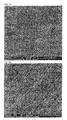
- FIGS. 1 and 2 are photos of a braided glass cord depicting a zone which was resin blocked using paraffin wax infused under a controlled thermal gradient and from which the paraffin was subsequently removed by vacuum sublimation and subsequent solution.
- FIG. 3 is a photo of a carbon fabric, from left to right, untreated, the PVA infused surface, and the surface opposite the PVA infused surface.
- FIG. 4 is a photo of a carbon fabric, from left to right, untreated, the PVA infused surface, and the surface opposite the PVA infused surface.
- FIG. 5 is an example time-temperature diagram of a process in accordance with one aspect of this invention.
- FIGS. 6 a and 6 b are scanning electron micrographs of carbon fibers exposed on the surface of a cured composite structure prepared in accordance with one aspect of this invention.
- FIG. 7 is a schematic diagram illustrating the infusion of reinforcing fabric with resin blocking substance in accordance with one aspect of the present invention.
- FIG. 8 is a schematic illustrating the controlled end-wise infusion of a resin blocking substance in accordance with one aspect of the present invention.
- FIG. 9 is an illustration of a unidirectional reinforcing tape prepared in accordance with one aspect of the present invention.
- FIG. 10 illustrates a joint connecting previously cured laminates in accordance with one aspect of the present invention.
- FIGS. 11 a through 11 e illustrate the sequence of construction of a joint between a strut and a honeycomb sandwich structure in accordance with the present invention.
- FIGS. 12 a and 12 b illustrate the preparation of a stepped lap joint in accordance with one aspect of the present invention.
- FIG. 13 a through 13 d illustrates the steps by which a dovetail joint may be produced in accordance with the present invention.
- a braided glass fiber cord at an initial temperature of 20 deg C. has been momentarily dipped in molten paraffin so as to allow infusion (wicking) of the molten paraffin to an intended future resin boundary.
- the infusion extends to a boundary 2 at which the molten paraffin dropped in temperature sufficiently to begin solidification and ceases to infuse.
- a transient temperature gradient thus controlled the extent of paraffin infusion.
- the paraffin in this case was used as a resin blocking substance.
- the specimen shown in FIGS. 1 and 2 was subsequently cooled to solidify the paraffin, infused with epoxy resin which that was then allowed to cure, and then cleaned of paraffin by sublimation and solution.
- the infusion of epoxy resin was precisely controlled by the paraffin infusion boundary 2 between glass fiber infused with subsequently cured epoxy resin 3 and non-infused glass fiber 1 .
- Such an arrangement is useful for a wide variety of fiber reinforced composite articles that are to be subsequently bonded, or for which flexible non-infused fibers may serve other purposes such as for flexure, heat transfer, or bonding of special purpose coatings thereto.
- a square woven carbon fiber cloth is shown on the left side of the photo.
- the center portion of the photo shows one surface of the same woven carbon fiber cloth infused with plasticized polyvinyl alcohol (PVA) under conditions of a through-thickness temperature gradient.
- the left hand portion of the photo of FIG. 3 shows the surface of the cloth opposite the surface from which the PVA was infused. This was the cold surface.
- the through-thickness temperature gradient caused the PVA to gel and cease infusion at the intended boundary within the material.
- a specimen was thus produced which may be used as the outermost layer of reinforcement, at a portion of a surface to be subsequently bonded, of a fiber reinforced component.
- the exposed fibers would be incorporated directly into the component, while the PVA infused fibers would be protected or blocked from resin infusion until after the resin was cured and could no longer migrate, after which the PVA could be removed with hot water at any time prior to final assembly and bonding.
- the PVA treated fabric of the type shown in FIG. 3 may also be infused with resin and then partially cured or gelled to provide a pre-preg material suitable for use on to-be-subsequently-bonded-or-coated surfaces of articles built up using pre-preg materials.
- FIG. 4 a woven glass fiber cloth is shown.
- the left hand portion of the photo shows untreated fabric
- the middle portion of the photo shows the PVA treated surface
- the right hand side of the photo shows the surface opposite the PVA treated side. All of the description relating to FIG. 3 also applies to FIG. 4 , except for the difference in fabric material; i.e., carbon for FIG. 3 and glass for FIG. 4 .
- a melting point reduced resin blocking substance is prepared.
- a cold drum or other suitable heat transfer surface is temperature controlled to a temperature below the gel point of the melting point reduced resin blocking substance. Note that the aforementioned stage is preparatory in nature and that the following fabric treatment stages are generally suitable for a continuous process flow.
- Fabric is brought into tight contact with the cold drum while molten melting point reduced resin blocking substance is brought into contact, by dipping for example, with the fabric.
- the melting point reduced resin blocking substance may be, for example, PVA in aqueous solution.
- PVA if used, is preferably plasticized with 1 to 3% glycerol or ethylene glycol in order to provide flexibility to the infused fabric.
- the temperature gradient required in order to infuse then stop the resin blocking substance may be either transient or steady state in nature or a combination thereof. A temperature gradient of some type is, in any case, a salient feature of this process.
- the fabric is used as intended in order to provide exposed fibers at the surface of a resin infused fiber reinforced component.
- the curing of such fiber reinforced components may require elevated curing temperatures which would have caused the original melting point reduced resin blocking substance to melt.
- the dry form of the resin blocking substance is, conversely, compatible with such elevated temperature cure cycles.
- the resin blocking substance may be dissolved or otherwise removed from the surface of the component in order to provide exposed fibers to which a reliable bond may be readily achieved. It should be noted that it may be desirable to transport and store such components with the resin blocking substance still in place in order to prevent damage to or contamination of the to-be-bonded fibers.
- FIGS. 6 a and 6 b exposed carbon fibers within the surface of a square woven carbon fiber fabric are shown in scanning electron micrographs.
- This specimen was prepared by the use of thermal gradient controlled infusion of melting point reduced plasticized PVA into the surface of the fabric shown.
- the fabric prepared in accordance with this invention was then incorporated with its resin blocked fibers toward the surface as the outermost layer of a multi-layer laminate. Infusion of epoxy resin into the fibers shown in the electron micrographs of FIGS. 6 a and 6 b was thus prevented. After curing of the epoxy the resin blocking PVA compound was removed with hot water.
- This specimen provides a surface which provides continuity of reinforcement from within the specimen into subsequently applied adhesives or coatings.
- FIG. 7 the dipping stage of FIG. 5 is illustrated.
- Fabric 4 is held against cold drum 5 by tension.
- Applicator roll 6 applies a resin blocking substance such as melting point reduced plasticized PVA to the surface of the fabric.
- the dew point in the vicinity of the cold drum should be held below the temperature of the cold drum. Condensed water on the cold drum could wick into the fabric and come into contact with the resin blocking substance, further depressing its melting point and causing uncontrolled infusion of the resin blocking substance into the fabric.
- the speed and temperature of the cold drum may be controlled in order to obtain optimum penetration of the resin blocking substance. Approximately 50% through thickness penetration may be desirable for many applications.
- a dryer 7 renders the coated fabric non-sticky and suitable for handling, storage, and subsequent resin infusion or coating application. It should be noted that flexible coatings may be applied to the non-resin-blocked surface of the fabric prior to incorporation into the final article. In such case the resin blocking substance would be dissolved prior to assembly.
- FIG. 8 a process is illustrated wherein a temperature gradient is established in order to control edgewise infusion of a resin blocking substance into the edge or end of a sheet fabric.
- Heat sink 8 creates a cold zone within fabric 4 in order to limit infusion of resin blocking substance 9 .
- fabric 4 is infused on its end with resin blocking substance 9 to form a resin blocker infused zone 11 .
- the fabric may then be assembled, infused with resin and cured in order to form a laminate 12 with edges 13 suitable for creation of high strength interleaved joints 14 .
- the blocking substance may be removed from the edges of the fabric in order to allow interleaving and adhesive of the fabric layers.
- FIGS. 11 a , 11 b , 11 c , 11 d , and 11 e the salient steps for bonding a rib to a honeycomb panel are illustrated.
- FIG. 11 a shows the application of a prepared strip of fabric 20 which is resin blocked on one surface 20 a and infused with pre-preg resin on the other surface 20 b .
- the pre-preg surface 20 b is applied to the uncured honeycomb structure 21 which is also of pre-preg construction.
- FIG. 11 b shows the arrangement of peel ply 17 , breather 18 and vacuum bag 19 relative to the prepared strip of fabric 20 .
- FIG. 11 c shows the removal, after curing, of the resin blocking substance.
- FIG. 11 a shows the application of a prepared strip of fabric 20 which is resin blocked on one surface 20 a and infused with pre-preg resin on the other surface 20 b .
- the pre-preg surface 20 b is applied to the uncured honeycomb structure 21 which is also of pre-pre
- FIG. 11 d shows the application of strip (B-stage) adhesive 15 between the aforementioned prepared surface and the similarly prepared surface of a rib 16 .
- FIG. 11 e illustrates the arrangement of peel ply, breather and vacuum bag relative to the prepared joint in preparation for curing of the joining adhesive.
- Laminate 22 a is co-cured with bonding prepared bonding strip 20 a .
- Laminate 22 b is likewise co-cured with bonding strip 20 b .
- the joint is completed by removal of the resin blocking substance from bonding strips 20 a and 20 b and the application and curing of adhesive.
- Adhesive may be of any suitable variety such as liquid, gel, paste, or B-stage sheet adhesive. In the case of sheet adhesive, vacuum bag curing as illustrated in FIG. 11 e might be used.
- FIGS. 13 a , 13 b , 13 c , and 13 c the construction of a dovetail joint is illustrated wherein fibers are continuous from within a cured component 23 into a dovetail receptacle 24 within structure 33 .
- the portion of the reinforcing fibers which are to form the dovetail connection 31 a , 31 b , 31 c , 31 d , and 31 e are infused with resin blocking substance prior to curing of component 23 .
- Spaces 28 a , 28 b , 28 c , 28 d , and 28 e may be blocked with elastomeric wedges, for example, during resin infusion and curing of component 23 .
- FIG. 13 c illustrates an example curing arrangement which provides for evacuation of receptacle 24 and subsequent resin infusion.
- Vacuum/resin injection line 30 is connected to cavity 24 which is sealed by gum tape 32 .
- each of the connection means as herein disclosed and described ii) the related methods disclosed and described, iii) similar, equivalent, and even implicit variations of each of these devices and methods, iv) those alternative designs which accomplish each of the functions shown as are disclosed and described, v) those alternative designs and methods which accomplish each of the functions shown as are implicit to accomplish that which is disclosed and described, vi) each feature, component, and step shown as separate and independent inventions, vii) the applications enhanced by the various systems or components disclosed, viii) the resulting products produced by such systems or components, ix) methods and apparatuses substantially as described hereinbefore and with reference to any of the accompanying examples, x) the various combinations and permutations of each of the elements disclosed, xi) each potentially dependent claim or concept as a dependency on each and every one of the independent claims or concepts presented, and xxii) the various combinations and permutations of each of the above.
Abstract
Description
- J. M. Koyler, et al, Intl. SAMPE Tech. Conf. Series, 45, 365 (2000).
- D. M. Gleich, et al, Intl. SAMPE Tech. Conf. Series, 45, 818 (2000).
- R. H. Bossi, R. L. Nereberg, Intl. SAMPE Tech. Conf. Series, 45, 1787 (2000).
- Heselhurst R. B., Joining Composite Structures, Tutorial notes SAMPE 2001.
The above mentioned references are hereby incorporated by reference. U.S. Pat. No. 5,464,059 to Jacaruso et al discloses partial embedment of reinforcing fabric in thermoplastic materials for subsequent connection of thermoset composite structures, but without fiber continuity through the completed thermoset/thermoplastic/thermoset joints suggested therein. The various processes for increasing the surface energy and availability of potential bond sites are labor intensive, expensive, of dubious reliability, and are subject to reversal by brief environmental exposure.
Claims (39)
Priority Applications (1)
| Application Number | Priority Date | Filing Date | Title |
|---|---|---|---|
| US11/792,903 US8470404B2 (en) | 2004-08-31 | 2005-08-31 | Process of manufacturing fiber reinforced composite via selective infusion of resin and resin blocking substance |
Applications Claiming Priority (3)
| Application Number | Priority Date | Filing Date | Title |
|---|---|---|---|
| US60623104P | 2004-08-31 | 2004-08-31 | |
| US11/792,903 US8470404B2 (en) | 2004-08-31 | 2005-08-31 | Process of manufacturing fiber reinforced composite via selective infusion of resin and resin blocking substance |
| PCT/US2005/031243 WO2006026734A2 (en) | 2004-08-31 | 2005-08-31 | High strength joining system for fiber reinforced composites |
Related Parent Applications (1)
| Application Number | Title | Priority Date | Filing Date |
|---|---|---|---|
| PCT/US2005/031243 A-371-Of-International WO2006026734A2 (en) | 2004-08-31 | 2005-08-31 | High strength joining system for fiber reinforced composites |
Related Child Applications (1)
| Application Number | Title | Priority Date | Filing Date |
|---|---|---|---|
| US13/926,809 Continuation US20140138026A1 (en) | 2004-08-31 | 2013-06-25 | High Strength Joining System For Fiber Reinforced Composites |
Publications (2)
| Publication Number | Publication Date |
|---|---|
| US20090068365A1 US20090068365A1 (en) | 2009-03-12 |
| US8470404B2 true US8470404B2 (en) | 2013-06-25 |
Family
ID=36000741
Family Applications (2)
| Application Number | Title | Priority Date | Filing Date |
|---|---|---|---|
| US11/792,903 Expired - Fee Related US8470404B2 (en) | 2004-08-31 | 2005-08-31 | Process of manufacturing fiber reinforced composite via selective infusion of resin and resin blocking substance |
| US13/926,809 Abandoned US20140138026A1 (en) | 2004-08-31 | 2013-06-25 | High Strength Joining System For Fiber Reinforced Composites |
Family Applications After (1)
| Application Number | Title | Priority Date | Filing Date |
|---|---|---|---|
| US13/926,809 Abandoned US20140138026A1 (en) | 2004-08-31 | 2013-06-25 | High Strength Joining System For Fiber Reinforced Composites |
Country Status (12)
| Country | Link |
|---|---|
| US (2) | US8470404B2 (en) |
| EP (1) | EP1791997B1 (en) |
| KR (2) | KR20120088843A (en) |
| CN (1) | CN101043954B (en) |
| AT (1) | ATE556166T1 (en) |
| AU (1) | AU2005279775B2 (en) |
| CA (1) | CA2620563C (en) |
| DK (1) | DK1791997T3 (en) |
| EA (1) | EA010821B1 (en) |
| ES (1) | ES2386026T3 (en) |
| MX (1) | MX2007003695A (en) |
| WO (1) | WO2006026734A2 (en) |
Cited By (3)
| Publication number | Priority date | Publication date | Assignee | Title |
|---|---|---|---|---|
| US10179282B2 (en) | 2016-02-26 | 2019-01-15 | Impyrium, Inc. | Joystick input apparatus with living hinges |
| US10189219B2 (en) | 2013-10-04 | 2019-01-29 | United Technologies Corporation | Method of fabricating a ceramic article |
| US11826965B2 (en) | 2021-06-07 | 2023-11-28 | The Boeing Company | Method for making consolidated composite structures |
Families Citing this family (7)
| Publication number | Priority date | Publication date | Assignee | Title |
|---|---|---|---|---|
| ITPD20120065A1 (en) * | 2012-03-05 | 2013-09-06 | Everlux S R L | PROCEDURE FOR THE REALIZATION OF A MATTER CONTAINING AEROGEL AND PLANT TO REALIZE THIS PROCEDURE |
| US10035323B2 (en) * | 2013-09-23 | 2018-07-31 | The Boeing Company | Composite textiles including spread filaments |
| ES2875924T3 (en) | 2014-02-06 | 2021-11-11 | Owens Corning Intellectual Capital Llc | Fiber-reinforced composite materials |
| FR3021898B1 (en) * | 2014-06-10 | 2016-07-15 | Daher Aerospace | METHOD FOR ASSEMBLING A SET OF COMPOSITE PARTS AND ASSEMBLY OBTAINED BY SUCH A METHOD |
| JP6107787B2 (en) * | 2014-10-29 | 2017-04-05 | トヨタ自動車株式会社 | Manufacturing method of fiber reinforced resin molded member and connecting method of member |
| US10994468B2 (en) * | 2018-04-11 | 2021-05-04 | Clemson University Research Foundation | Foldable composite structures |
| IT201900022026A1 (en) * | 2019-11-25 | 2021-05-25 | Torino Politecnico | Process of acid etching of the surface of polymeric matrix composites without interrupting the continuity of the fibers, in order to improve the mechanical strength of a joint |
Citations (108)
| Publication number | Priority date | Publication date | Assignee | Title |
|---|---|---|---|---|
| US3185605A (en) * | 1959-08-21 | 1965-05-25 | Bristol Siddeley Engines Ltd | Methods of making resin reinforced articles |
| US4745008A (en) | 1986-04-16 | 1988-05-17 | United States Of America As Represented By The Secretary Of The Air Force | Process for carbon-carbon composite fabrication |
| US4856136A (en) | 1988-05-06 | 1989-08-15 | Padco, Inc. | Flocked foam brush |
| US4869954A (en) | 1987-09-10 | 1989-09-26 | Chomerics, Inc. | Thermally conductive materials |
| US4888228A (en) | 1988-08-29 | 1989-12-19 | The B. F. Goodrich Company | Composite laminates comprising matrix bound plies having interlocked transverse fibers and a method of making the same |
| US4931125A (en) | 1985-06-18 | 1990-06-05 | The Dow Chemical Company | Method for adhesive bonding with pretreatment of components |
| US4946736A (en) | 1987-08-06 | 1990-08-07 | W. L. Gore & Associates, Inc. | Protective electromagnetically transparent window |
| US4955970A (en) | 1987-10-16 | 1990-09-11 | Exel Oy | Method of forming a joint between a connecting piece and a product formed of composite material, said joint, and said connecting piece for forming said joint |
| US4957805A (en) | 1986-07-31 | 1990-09-18 | The Wiggins Teape Group Limited | Method of making laminated reinforced thermoplastic sheets and articles made therefrom |
| US4968383A (en) | 1985-06-18 | 1990-11-06 | The Dow Chemical Company | Method for molding over a preform |
| US5014161A (en) | 1985-07-22 | 1991-05-07 | Digital Equipment Corporation | System for detachably mounting semiconductors on conductor substrate |
| US5077637A (en) | 1989-09-25 | 1991-12-31 | The Charles Stark Draper Lab., Inc. | Solid state directional thermal cable |
| US5095628A (en) | 1990-08-09 | 1992-03-17 | Teledyne Industries, Inc. | Process of forming a rigid-flex circuit |
| US5133994A (en) * | 1990-03-15 | 1992-07-28 | Societe Europeenne De Propulsion | Process for forming a folding or separation line in the manufacture of a composite material component |
| US5150748A (en) | 1990-06-18 | 1992-09-29 | Mcdonnell Douglas Corporation | Advanced survivable radiator |
| US5178924A (en) | 1991-06-17 | 1993-01-12 | Minnesota Mining And Manufacturing Company | Release liner |
| US5187018A (en) | 1985-03-24 | 1993-02-16 | Atochem | Fiber-reinforced thermoplastic polymer composite and process for preparation thereof |
| US5197928A (en) | 1989-11-20 | 1993-03-30 | Mitsuboshi Belting Ltd. | V-ribbed belt having protruding fibers |
| US5213868A (en) | 1991-08-13 | 1993-05-25 | Chomerics, Inc. | Thermally conductive interface materials and methods of using the same |
| US5236771A (en) | 1991-02-25 | 1993-08-17 | Lainiere De Picardie | Composite lining fabric and process for producing it |
| EP0341993B1 (en) | 1988-05-13 | 1993-08-18 | Minnesota Mining And Manufacturing Company | Sheet material for forming the loop portion for hook and loop fasteners |
| US5264059A (en) | 1990-12-17 | 1993-11-23 | United Technologies Corporation | Method of making thermoplastic adhesive strip for bonding thermoset composite structures |
| US5306188A (en) * | 1991-11-06 | 1994-04-26 | Surfco Hawaii | Method of applying a safety/maneuver enhancing fin to a surfboard |
| US5322580A (en) | 1992-04-24 | 1994-06-21 | United Technologies Corporation | Bonding of thermoset composite structures to metal structures |
| US5330604A (en) | 1991-04-05 | 1994-07-19 | Scapa Group Plc | Edge jointing of fabrics |
| US5333532A (en) | 1988-06-03 | 1994-08-02 | Foster-Miller, Inc. | Survivability enhancement |
| US5350545A (en) | 1991-05-01 | 1994-09-27 | General Atomics | Method of fabrication of composites |
| US5402006A (en) | 1992-11-10 | 1995-03-28 | Texas Instruments Incorporated | Semiconductor device with enhanced adhesion between heat spreader and leads and plastic mold compound |
| US5419927A (en) | 1988-09-26 | 1995-05-30 | Chromalloy Gas Turbine Corporation | Process for coating fiber reinforced ceramic composites |
| US5424353A (en) | 1991-12-05 | 1995-06-13 | Aerospatiale Societe Nationale Industrielle | Molding material containing refractory fibers, usable in the manufacture of ablatable pieces, process for manufacturing same and applications thereof |
| US5455458A (en) | 1993-08-09 | 1995-10-03 | Hughes Aircraft Company | Phase change cooling of semiconductor power modules |
| FR2718074A1 (en) * | 1994-04-01 | 1995-10-06 | Snecma | Fabrication of complex composite material parts |
| US5466506A (en) | 1992-10-27 | 1995-11-14 | Foster-Miller, Inc. | Translaminar reinforcement system for Z-direction reinforcement of a fiber matrix structure |
| US5542471A (en) | 1993-11-16 | 1996-08-06 | Loral Vought System Corporation | Heat transfer element having the thermally conductive fibers |
| US5549771A (en) | 1994-12-23 | 1996-08-27 | Brooker; David A. | Fabrication of body containing lengths of fiber embedded therein |
| US5554997A (en) | 1989-08-29 | 1996-09-10 | Hughes Aircraft Company | Graphite composite structures exhibiting electrical conductivity |
| US5556565A (en) | 1995-06-07 | 1996-09-17 | The Boeing Company | Method for composite welding using a hybrid metal webbed composite beam |
| US5589015A (en) | 1994-06-07 | 1996-12-31 | Foster-Miller, Inc. | Method and system for inserting reinforcing elements in a composite structure |
| US5601930A (en) * | 1994-04-13 | 1997-02-11 | The Mead Corporation | Decor sheet and decorative laminates prepared therefrom |
| US5637375A (en) | 1988-01-20 | 1997-06-10 | Loral Vought Systems Corporation | Composite products and method of preparation |
| US5643390A (en) | 1995-05-04 | 1997-07-01 | The University Of Delaware | Bonding techniques for high performance thermoplastic compositions |
| US5662757A (en) | 1994-10-17 | 1997-09-02 | General Electric Company | Method of removing an abradable shroud assembly for turbomachinery |
| US5667859A (en) | 1993-04-30 | 1997-09-16 | Foster-Miller, Inc. | Reinforced joint for composite structures and method of joining composite parts |
| US5672311A (en) | 1990-02-09 | 1997-09-30 | Shell Oil Company | Process for preparing thermoset composite articles |
| US5674585A (en) | 1995-11-15 | 1997-10-07 | United Technologies Corporation | Composite thermal insulation structure |
| US5688426A (en) | 1995-06-07 | 1997-11-18 | The Boeing Company | Hybrid metal webbed composite beam |
| US5695847A (en) | 1996-07-10 | 1997-12-09 | Browne; James M. | Thermally conductive joining film |
| US5725707A (en) | 1995-04-10 | 1998-03-10 | Northrop Grumman Corporation | Enhanced conductive joints from fiber flocking |
| US5726495A (en) | 1992-03-09 | 1998-03-10 | Sumitomo Metal Industries, Ltd. | Heat sink having good heat dissipating characteristics |
| US5736222A (en) | 1995-11-01 | 1998-04-07 | The Boeing Company | Interlaced Z-pin structures |
| US5741574A (en) | 1993-05-04 | 1998-04-21 | Foster-Miller, Inc. | Truss reinforced foam core sandwich |
| US5762741A (en) | 1993-12-21 | 1998-06-09 | E.I. Du Pont De Nemours And Company | Method for bonding polymeric articles |
| US5773122A (en) | 1990-10-01 | 1998-06-30 | Fiber Materials, Inc. | Reinforced carbon composites |
| US5789061A (en) | 1996-02-13 | 1998-08-04 | Foster-Miller, Inc. | Stiffener reinforced assembly and method of manufacturing same |
| US5800672A (en) | 1994-06-07 | 1998-09-01 | Aztex, Inc. | Ultrasonic fastening system and method |
| US5829716A (en) | 1995-06-07 | 1998-11-03 | The Boeing Company | Welded aerospace structure using a hybrid metal webbed composite beam |
| US5832594A (en) | 1996-05-31 | 1998-11-10 | The Boeing Company | Tooling for inserting Z-pins |
| US5852548A (en) | 1994-09-09 | 1998-12-22 | Northrop Grumman Corporation | Enhanced heat transfer in printed circuit boards and electronic components thereof |
| US5858537A (en) | 1996-05-31 | 1999-01-12 | The United States Of America As Represented By The Secretary Of The Navy | Compliant attachment |
| US5863635A (en) | 1996-05-31 | 1999-01-26 | The Boeing Company | Composite detail having Z-pin stubble |
| US5862975A (en) | 1996-03-20 | 1999-01-26 | The Boeing Company | Composite/metal structural joint with welded Z-pins |
| US5868886A (en) | 1995-12-22 | 1999-02-09 | Alston; Mark S. | Z-pin reinforced bonded composite repairs |
| US5869165A (en) | 1996-04-05 | 1999-02-09 | The Boeing Company | Highly ordered Z-pin structures |
| US5873973A (en) | 1995-04-13 | 1999-02-23 | Northrop Grumman Corporation | Method for single filament transverse reinforcement in composite prepreg material |
| US5876832A (en) | 1996-05-31 | 1999-03-02 | Pannell; Shawn D. | Precured strips for Z-pin joining of composites |
| US5879492A (en) | 1998-04-17 | 1999-03-09 | Northrop Grumman Corporation | Z-peel sheets |
| US5904796A (en) | 1996-12-05 | 1999-05-18 | Power Devices, Inc. | Adhesive thermal interface and method of making the same |
| US5916469A (en) | 1996-06-06 | 1999-06-29 | The Boeing Company | Susceptor integration into reinforced thermoplastic composites |
| US5921754A (en) | 1996-08-26 | 1999-07-13 | Foster-Miller, Inc. | Composite turbine rotor |
| US5942064A (en) | 1996-09-06 | 1999-08-24 | Deutsche Forchungsanstalt Fur-Und Raumfahrt E.V.1 | Process for permanently joining at least two structural components together to form a molded body |
| US5948501A (en) | 1995-08-23 | 1999-09-07 | Obermeyer; Henry K. | Composite to metal structural connection |
| EP0970800A2 (en) | 1998-06-12 | 2000-01-12 | Foster-Miller, Inc. | Continuous intersecting braided composite structure and method of making same |
| US6042671A (en) | 1997-06-20 | 2000-03-28 | Agency For Defense Development | Members having improved adhesion and sealing performance for rocket nozzle and fabrication method thereof |
| US6051089A (en) | 1997-02-07 | 2000-04-18 | Mcdonnell Douglas Corporation | Reinforcing member for composite workpieces and associated methods |
| US6054198A (en) | 1996-04-29 | 2000-04-25 | Parker-Hannifin Corporation | Conformal thermal interface material for electronic components |
| US6084775A (en) | 1998-12-09 | 2000-07-04 | International Business Machines Corporation | Heatsink and package structures with fusible release layer |
| US6090484A (en) | 1995-05-19 | 2000-07-18 | The Bergquist Company | Thermally conductive filled polymer composites for mounting electronic devices and method of application |
| US6096414A (en) | 1997-11-25 | 2000-08-01 | Parker-Hannifin Corporation | High dielectric strength thermal interface material |
| US6190602B1 (en) | 1998-03-13 | 2001-02-20 | Aztex, Inc. | Method of manufacturing a perforated laminate |
| US6231928B1 (en) * | 1999-08-30 | 2001-05-15 | Albany International Corp. | Method for manufacturing resin-impregnated endless belt structures for papermaking machines and similar industrial applications |
| US6291049B1 (en) | 1998-10-20 | 2001-09-18 | Aztex, Inc. | Sandwich structure and method of making same |
| EP0713369B1 (en) | 1993-07-06 | 2001-09-19 | Velcro Industries B.V. | Method of producing a hook or loop component |
| US6357487B2 (en) | 2000-04-28 | 2002-03-19 | Ykk Corporation | Surface fastener with double weaving structure |
| US6397438B1 (en) | 2000-09-26 | 2002-06-04 | Dewan Thomas E. | Embedded hook and loop fastener |
| US6416135B1 (en) | 2000-06-30 | 2002-07-09 | Accuride Corporation | Means and method for attaching FRP wheels |
| US6425985B1 (en) | 1998-06-10 | 2002-07-30 | Tamfelt Oyj Abp | Method of manufacturing press felt, and press felt |
| US6436506B1 (en) | 1998-06-24 | 2002-08-20 | Honeywell International Inc. | Transferrable compliant fibrous thermal interface |
| US6481063B2 (en) | 1998-11-06 | 2002-11-19 | Velcro Industries B.V. | Composite hook and loop fasteners, methods of their manufacture, and products containing them |
| US6511563B2 (en) | 1991-03-01 | 2003-01-28 | Foster-Miller, Inc. | Device for ultrasonically consolidating fiber reinforced composite structures |
| US6524681B1 (en) * | 1997-04-08 | 2003-02-25 | 3M Innovative Properties Company | Patterned surface friction materials, clutch plate members and methods of making and using same |
| WO2003020495A1 (en) | 2001-08-28 | 2003-03-13 | Lockheed Martin Corporation | Method of hot-melt resin impregnation of 3-d, woven, textile preforms |
| US6612523B2 (en) | 2001-12-21 | 2003-09-02 | Lockheed Martin Corporation | Aircraft structures having improved through-thickness thermal conductivity |
| US20030196741A1 (en) | 2002-04-05 | 2003-10-23 | The Boeing Company | Textile joint reinforcement and associated method |
| US6645333B2 (en) | 2001-04-06 | 2003-11-11 | Ebert Composites Corporation | Method of inserting z-axis reinforcing fibers into a composite laminate |
| US6645610B1 (en) | 1998-04-20 | 2003-11-11 | Northrop Grumann | Cured composite material formed utilizing Z-peel sheets |
| US20030214064A1 (en) | 2002-05-20 | 2003-11-20 | Shin Hyun Kyu | Method for manufacturing carbon-carbon composites |
| US6656403B1 (en) | 1998-11-06 | 2003-12-02 | Velcro Industries B.V. | Securing loop materials |
| US6676785B2 (en) | 2001-04-06 | 2004-01-13 | Ebert Composites Corporation | Method of clinching the top and bottom ends of Z-axis fibers into the respective top and bottom surfaces of a composite laminate |
| US6679913B2 (en) | 1998-04-14 | 2004-01-20 | Tranquil Prospects Ltd. | Implantable sheet material |
| US6713151B1 (en) | 1998-06-24 | 2004-03-30 | Honeywell International Inc. | Compliant fibrous thermal interface |
| US20040081791A1 (en) | 2002-07-03 | 2004-04-29 | Abrams Louis Brown | Flocked articles and methods of making same |
| US6746741B2 (en) | 2000-12-13 | 2004-06-08 | Donald Edward Wheatley | Carbon fiber reinforcement system |
| EP1428650A1 (en) | 2002-12-13 | 2004-06-16 | Hexcel Composites Limited | Improvements in or relating to the preparation of fibre-reinforced composites |
| US20040213942A1 (en) | 2003-04-25 | 2004-10-28 | Nitto Denko Corporation | Pressure-sensitive adhesive tape or sheet, and method for producing it |
| US6821368B2 (en) | 2001-10-09 | 2004-11-23 | Lockheed Martin Corporation | Co-bonded joint with Z-pins |
| US20050024004A1 (en) | 2003-07-28 | 2005-02-03 | Cablecam International Inc. | Cabling system and method for facilitating fluid three-dimensional movement of a suspended camera |
| US20050053787A1 (en) | 2001-12-06 | 2005-03-10 | Masaki Yamasaki | Fiber-reinforced composite material and method for production thereof |
| JP4033836B2 (en) | 2002-02-01 | 2008-01-16 | コーニンクレッカ フィリップス エレクトロニクス エヌ ヴィ | Compression of paletted color images using variable-length color codes |
Family Cites Families (6)
| Publication number | Priority date | Publication date | Assignee | Title |
|---|---|---|---|---|
| JPS6088094A (en) | 1983-10-20 | 1985-05-17 | Nippon Oil & Fats Co Ltd | Lubricating oil composition |
| JPH0433836A (en) * | 1990-05-30 | 1992-02-05 | Hitachi Chem Co Ltd | F.r.p molding with suede-like matt surface and manufacture thereof |
| NO179421C (en) | 1993-03-26 | 1996-10-02 | Statoil As | Apparatus for distributing a stream of injection fluid into separate zones in a basic formation |
| DE4401813A1 (en) * | 1994-01-22 | 1995-07-27 | Hella Kg Hueck & Co | Molded parts that can withstand high heat |
| JPH11296904A (en) * | 1998-04-03 | 1999-10-29 | Toshiba Corp | Information recording medium and manufacture of resin substrate used for the same |
| US6712099B2 (en) | 2001-06-15 | 2004-03-30 | Lockheed Martin Corporation | Three-dimensional weave architecture |
-
2005
- 2005-08-31 US US11/792,903 patent/US8470404B2/en not_active Expired - Fee Related
- 2005-08-31 AT AT05813025T patent/ATE556166T1/en active
- 2005-08-31 WO PCT/US2005/031243 patent/WO2006026734A2/en active Application Filing
- 2005-08-31 ES ES05813025T patent/ES2386026T3/en active Active
- 2005-08-31 MX MX2007003695A patent/MX2007003695A/en active IP Right Grant
- 2005-08-31 EA EA200700520A patent/EA010821B1/en not_active IP Right Cessation
- 2005-08-31 CA CA2620563A patent/CA2620563C/en not_active Expired - Fee Related
- 2005-08-31 KR KR1020127015502A patent/KR20120088843A/en not_active Application Discontinuation
- 2005-08-31 AU AU2005279775A patent/AU2005279775B2/en not_active Ceased
- 2005-08-31 EP EP05813025A patent/EP1791997B1/en not_active Not-in-force
- 2005-08-31 CN CN2005800359780A patent/CN101043954B/en not_active Expired - Fee Related
- 2005-08-31 DK DK05813025.3T patent/DK1791997T3/en active
- 2005-08-31 KR KR1020077006442A patent/KR101226541B1/en not_active IP Right Cessation
-
2013
- 2013-06-25 US US13/926,809 patent/US20140138026A1/en not_active Abandoned
Patent Citations (127)
| Publication number | Priority date | Publication date | Assignee | Title |
|---|---|---|---|---|
| US3185605A (en) * | 1959-08-21 | 1965-05-25 | Bristol Siddeley Engines Ltd | Methods of making resin reinforced articles |
| US5187018A (en) | 1985-03-24 | 1993-02-16 | Atochem | Fiber-reinforced thermoplastic polymer composite and process for preparation thereof |
| US4931125A (en) | 1985-06-18 | 1990-06-05 | The Dow Chemical Company | Method for adhesive bonding with pretreatment of components |
| US4968383A (en) | 1985-06-18 | 1990-11-06 | The Dow Chemical Company | Method for molding over a preform |
| US5014161A (en) | 1985-07-22 | 1991-05-07 | Digital Equipment Corporation | System for detachably mounting semiconductors on conductor substrate |
| US4745008A (en) | 1986-04-16 | 1988-05-17 | United States Of America As Represented By The Secretary Of The Air Force | Process for carbon-carbon composite fabrication |
| US4957805A (en) | 1986-07-31 | 1990-09-18 | The Wiggins Teape Group Limited | Method of making laminated reinforced thermoplastic sheets and articles made therefrom |
| US4946736A (en) | 1987-08-06 | 1990-08-07 | W. L. Gore & Associates, Inc. | Protective electromagnetically transparent window |
| US4869954A (en) | 1987-09-10 | 1989-09-26 | Chomerics, Inc. | Thermally conductive materials |
| US4955970A (en) | 1987-10-16 | 1990-09-11 | Exel Oy | Method of forming a joint between a connecting piece and a product formed of composite material, said joint, and said connecting piece for forming said joint |
| US5637375A (en) | 1988-01-20 | 1997-06-10 | Loral Vought Systems Corporation | Composite products and method of preparation |
| US4856136A (en) | 1988-05-06 | 1989-08-15 | Padco, Inc. | Flocked foam brush |
| EP0341993B1 (en) | 1988-05-13 | 1993-08-18 | Minnesota Mining And Manufacturing Company | Sheet material for forming the loop portion for hook and loop fasteners |
| US5333532A (en) | 1988-06-03 | 1994-08-02 | Foster-Miller, Inc. | Survivability enhancement |
| US4888228A (en) | 1988-08-29 | 1989-12-19 | The B. F. Goodrich Company | Composite laminates comprising matrix bound plies having interlocked transverse fibers and a method of making the same |
| US5419927A (en) | 1988-09-26 | 1995-05-30 | Chromalloy Gas Turbine Corporation | Process for coating fiber reinforced ceramic composites |
| US5554997A (en) | 1989-08-29 | 1996-09-10 | Hughes Aircraft Company | Graphite composite structures exhibiting electrical conductivity |
| US5077637A (en) | 1989-09-25 | 1991-12-31 | The Charles Stark Draper Lab., Inc. | Solid state directional thermal cable |
| US5197928A (en) | 1989-11-20 | 1993-03-30 | Mitsuboshi Belting Ltd. | V-ribbed belt having protruding fibers |
| US5672311A (en) | 1990-02-09 | 1997-09-30 | Shell Oil Company | Process for preparing thermoset composite articles |
| US5133994A (en) * | 1990-03-15 | 1992-07-28 | Societe Europeenne De Propulsion | Process for forming a folding or separation line in the manufacture of a composite material component |
| US5150748A (en) | 1990-06-18 | 1992-09-29 | Mcdonnell Douglas Corporation | Advanced survivable radiator |
| US5095628A (en) | 1990-08-09 | 1992-03-17 | Teledyne Industries, Inc. | Process of forming a rigid-flex circuit |
| US5773122A (en) | 1990-10-01 | 1998-06-30 | Fiber Materials, Inc. | Reinforced carbon composites |
| US5264059A (en) | 1990-12-17 | 1993-11-23 | United Technologies Corporation | Method of making thermoplastic adhesive strip for bonding thermoset composite structures |
| US5236771A (en) | 1991-02-25 | 1993-08-17 | Lainiere De Picardie | Composite lining fabric and process for producing it |
| US6511563B2 (en) | 1991-03-01 | 2003-01-28 | Foster-Miller, Inc. | Device for ultrasonically consolidating fiber reinforced composite structures |
| US5330604A (en) | 1991-04-05 | 1994-07-19 | Scapa Group Plc | Edge jointing of fabrics |
| US5350545A (en) | 1991-05-01 | 1994-09-27 | General Atomics | Method of fabrication of composites |
| US5178924A (en) | 1991-06-17 | 1993-01-12 | Minnesota Mining And Manufacturing Company | Release liner |
| US5213868A (en) | 1991-08-13 | 1993-05-25 | Chomerics, Inc. | Thermally conductive interface materials and methods of using the same |
| US5306188A (en) * | 1991-11-06 | 1994-04-26 | Surfco Hawaii | Method of applying a safety/maneuver enhancing fin to a surfboard |
| US5424353A (en) | 1991-12-05 | 1995-06-13 | Aerospatiale Societe Nationale Industrielle | Molding material containing refractory fibers, usable in the manufacture of ablatable pieces, process for manufacturing same and applications thereof |
| US5726495A (en) | 1992-03-09 | 1998-03-10 | Sumitomo Metal Industries, Ltd. | Heat sink having good heat dissipating characteristics |
| US5322580A (en) | 1992-04-24 | 1994-06-21 | United Technologies Corporation | Bonding of thermoset composite structures to metal structures |
| US5733404A (en) | 1992-10-27 | 1998-03-31 | Foster Miller, Inc. | Translaminar reinforcement system for Z-direction reinforcement of a fiber matrix structure |
| US5466506A (en) | 1992-10-27 | 1995-11-14 | Foster-Miller, Inc. | Translaminar reinforcement system for Z-direction reinforcement of a fiber matrix structure |
| US5402006A (en) | 1992-11-10 | 1995-03-28 | Texas Instruments Incorporated | Semiconductor device with enhanced adhesion between heat spreader and leads and plastic mold compound |
| US5667859A (en) | 1993-04-30 | 1997-09-16 | Foster-Miller, Inc. | Reinforced joint for composite structures and method of joining composite parts |
| US5741574A (en) | 1993-05-04 | 1998-04-21 | Foster-Miller, Inc. | Truss reinforced foam core sandwich |
| EP0713369B1 (en) | 1993-07-06 | 2001-09-19 | Velcro Industries B.V. | Method of producing a hook or loop component |
| US5455458A (en) | 1993-08-09 | 1995-10-03 | Hughes Aircraft Company | Phase change cooling of semiconductor power modules |
| US5542471A (en) | 1993-11-16 | 1996-08-06 | Loral Vought System Corporation | Heat transfer element having the thermally conductive fibers |
| US5762741A (en) | 1993-12-21 | 1998-06-09 | E.I. Du Pont De Nemours And Company | Method for bonding polymeric articles |
| FR2718074A1 (en) * | 1994-04-01 | 1995-10-06 | Snecma | Fabrication of complex composite material parts |
| US5601930A (en) * | 1994-04-13 | 1997-02-11 | The Mead Corporation | Decor sheet and decorative laminates prepared therefrom |
| US5800672A (en) | 1994-06-07 | 1998-09-01 | Aztex, Inc. | Ultrasonic fastening system and method |
| US5589015A (en) | 1994-06-07 | 1996-12-31 | Foster-Miller, Inc. | Method and system for inserting reinforcing elements in a composite structure |
| US5898570A (en) | 1994-09-09 | 1999-04-27 | Northrop Grumman Corporation | Enhanced heat transfer in printed circuit boards |
| US5852548A (en) | 1994-09-09 | 1998-12-22 | Northrop Grumman Corporation | Enhanced heat transfer in printed circuit boards and electronic components thereof |
| US5662757A (en) | 1994-10-17 | 1997-09-02 | General Electric Company | Method of removing an abradable shroud assembly for turbomachinery |
| US5683789A (en) | 1994-10-17 | 1997-11-04 | General Electric Company | Abradable shroud assembly for turbomachinery |
| US5549771A (en) | 1994-12-23 | 1996-08-27 | Brooker; David A. | Fabrication of body containing lengths of fiber embedded therein |
| US5725707A (en) | 1995-04-10 | 1998-03-10 | Northrop Grumman Corporation | Enhanced conductive joints from fiber flocking |
| US5873973A (en) | 1995-04-13 | 1999-02-23 | Northrop Grumman Corporation | Method for single filament transverse reinforcement in composite prepreg material |
| US5643390A (en) | 1995-05-04 | 1997-07-01 | The University Of Delaware | Bonding techniques for high performance thermoplastic compositions |
| US6090484A (en) | 1995-05-19 | 2000-07-18 | The Bergquist Company | Thermally conductive filled polymer composites for mounting electronic devices and method of application |
| US5688426A (en) | 1995-06-07 | 1997-11-18 | The Boeing Company | Hybrid metal webbed composite beam |
| US5829716A (en) | 1995-06-07 | 1998-11-03 | The Boeing Company | Welded aerospace structure using a hybrid metal webbed composite beam |
| US5556565A (en) | 1995-06-07 | 1996-09-17 | The Boeing Company | Method for composite welding using a hybrid metal webbed composite beam |
| US5948501A (en) | 1995-08-23 | 1999-09-07 | Obermeyer; Henry K. | Composite to metal structural connection |
| US5736222A (en) | 1995-11-01 | 1998-04-07 | The Boeing Company | Interlaced Z-pin structures |
| US6268049B1 (en) | 1995-11-01 | 2001-07-31 | James J. Childress | Circulation system using column core |
| US5958550A (en) | 1995-11-01 | 1999-09-28 | The Boeing Company | Z-pin-reinforced sandwich structure |
| US6027798A (en) | 1995-11-01 | 2000-02-22 | The Boeing Company | Pin-reinforced sandwich structure |
| US5674585A (en) | 1995-11-15 | 1997-10-07 | United Technologies Corporation | Composite thermal insulation structure |
| US5868886A (en) | 1995-12-22 | 1999-02-09 | Alston; Mark S. | Z-pin reinforced bonded composite repairs |
| US5882756A (en) | 1995-12-22 | 1999-03-16 | The Boeing Company | Composite patches having Z-pin reinforcement |
| US5789061A (en) | 1996-02-13 | 1998-08-04 | Foster-Miller, Inc. | Stiffener reinforced assembly and method of manufacturing same |
| US5827383A (en) | 1996-02-13 | 1998-10-27 | Foster-Miller, Inc. | Stiffener reinforced assembly and method of manufacturing same |
| US5972524A (en) | 1996-03-20 | 1999-10-26 | The Boering Company | Double lap joint with welded Z-pins |
| US5862975A (en) | 1996-03-20 | 1999-01-26 | The Boeing Company | Composite/metal structural joint with welded Z-pins |
| US5876652A (en) | 1996-04-05 | 1999-03-02 | The Boeing Company | Method for improving pulloff strength in pin-reinforced sandwich structure |
| US5869165A (en) | 1996-04-05 | 1999-02-09 | The Boeing Company | Highly ordered Z-pin structures |
| US6054198A (en) | 1996-04-29 | 2000-04-25 | Parker-Hannifin Corporation | Conformal thermal interface material for electronic components |
| US5858537A (en) | 1996-05-31 | 1999-01-12 | The United States Of America As Represented By The Secretary Of The Navy | Compliant attachment |
| US6436507B1 (en) | 1996-05-31 | 2002-08-20 | The Boeing Company | Composites joined with z-pin reinforcement |
| US5935698A (en) | 1996-05-31 | 1999-08-10 | The Boeing Company | Composites joined with precured, Z-pinned strips |
| US5876540A (en) | 1996-05-31 | 1999-03-02 | The Boeing Company | Joining composites using Z-pinned precured strips |
| US5863635A (en) | 1996-05-31 | 1999-01-26 | The Boeing Company | Composite detail having Z-pin stubble |
| US5919413A (en) | 1996-05-31 | 1999-07-06 | The Boeing Company | Method for inserting Z-pins |
| US5832594A (en) | 1996-05-31 | 1998-11-10 | The Boeing Company | Tooling for inserting Z-pins |
| US5968639A (en) | 1996-05-31 | 1999-10-19 | The Boeing Company | Z-pin reinforced, bonded composite structure |
| US5876832A (en) | 1996-05-31 | 1999-03-02 | Pannell; Shawn D. | Precured strips for Z-pin joining of composites |
| US5980665A (en) | 1996-05-31 | 1999-11-09 | The Boeing Company | Z-pin reinforced bonds for connecting composite structures |
| US5916469A (en) | 1996-06-06 | 1999-06-29 | The Boeing Company | Susceptor integration into reinforced thermoplastic composites |
| US5935475A (en) | 1996-06-06 | 1999-08-10 | The Boeing Company | Susceptor integration into reinforced thermoplastic composites |
| US5695847A (en) | 1996-07-10 | 1997-12-09 | Browne; James M. | Thermally conductive joining film |
| US5921754A (en) | 1996-08-26 | 1999-07-13 | Foster-Miller, Inc. | Composite turbine rotor |
| US5942064A (en) | 1996-09-06 | 1999-08-24 | Deutsche Forchungsanstalt Fur-Und Raumfahrt E.V.1 | Process for permanently joining at least two structural components together to form a molded body |
| US5904796A (en) | 1996-12-05 | 1999-05-18 | Power Devices, Inc. | Adhesive thermal interface and method of making the same |
| US6051089A (en) | 1997-02-07 | 2000-04-18 | Mcdonnell Douglas Corporation | Reinforcing member for composite workpieces and associated methods |
| US6524681B1 (en) * | 1997-04-08 | 2003-02-25 | 3M Innovative Properties Company | Patterned surface friction materials, clutch plate members and methods of making and using same |
| US6042671A (en) | 1997-06-20 | 2000-03-28 | Agency For Defense Development | Members having improved adhesion and sealing performance for rocket nozzle and fabrication method thereof |
| US6096414A (en) | 1997-11-25 | 2000-08-01 | Parker-Hannifin Corporation | High dielectric strength thermal interface material |
| US6190602B1 (en) | 1998-03-13 | 2001-02-20 | Aztex, Inc. | Method of manufacturing a perforated laminate |
| US6679913B2 (en) | 1998-04-14 | 2004-01-20 | Tranquil Prospects Ltd. | Implantable sheet material |
| US5879492A (en) | 1998-04-17 | 1999-03-09 | Northrop Grumman Corporation | Z-peel sheets |
| US6645610B1 (en) | 1998-04-20 | 2003-11-11 | Northrop Grumann | Cured composite material formed utilizing Z-peel sheets |
| US6425985B1 (en) | 1998-06-10 | 2002-07-30 | Tamfelt Oyj Abp | Method of manufacturing press felt, and press felt |
| US6647852B1 (en) | 1998-06-12 | 2003-11-18 | Glenn Freitas | Continuous intersecting braided composite structure and method of making same |
| EP0970800A2 (en) | 1998-06-12 | 2000-01-12 | Foster-Miller, Inc. | Continuous intersecting braided composite structure and method of making same |
| US6436506B1 (en) | 1998-06-24 | 2002-08-20 | Honeywell International Inc. | Transferrable compliant fibrous thermal interface |
| US6713151B1 (en) | 1998-06-24 | 2004-03-30 | Honeywell International Inc. | Compliant fibrous thermal interface |
| US6291049B1 (en) | 1998-10-20 | 2001-09-18 | Aztex, Inc. | Sandwich structure and method of making same |
| US6656403B1 (en) | 1998-11-06 | 2003-12-02 | Velcro Industries B.V. | Securing loop materials |
| US6481063B2 (en) | 1998-11-06 | 2002-11-19 | Velcro Industries B.V. | Composite hook and loop fasteners, methods of their manufacture, and products containing them |
| US6084775A (en) | 1998-12-09 | 2000-07-04 | International Business Machines Corporation | Heatsink and package structures with fusible release layer |
| US6231928B1 (en) * | 1999-08-30 | 2001-05-15 | Albany International Corp. | Method for manufacturing resin-impregnated endless belt structures for papermaking machines and similar industrial applications |
| US6357487B2 (en) | 2000-04-28 | 2002-03-19 | Ykk Corporation | Surface fastener with double weaving structure |
| US6416135B1 (en) | 2000-06-30 | 2002-07-09 | Accuride Corporation | Means and method for attaching FRP wheels |
| US6397438B1 (en) | 2000-09-26 | 2002-06-04 | Dewan Thomas E. | Embedded hook and loop fastener |
| US6746741B2 (en) | 2000-12-13 | 2004-06-08 | Donald Edward Wheatley | Carbon fiber reinforcement system |
| US6645333B2 (en) | 2001-04-06 | 2003-11-11 | Ebert Composites Corporation | Method of inserting z-axis reinforcing fibers into a composite laminate |
| US6676785B2 (en) | 2001-04-06 | 2004-01-13 | Ebert Composites Corporation | Method of clinching the top and bottom ends of Z-axis fibers into the respective top and bottom surfaces of a composite laminate |
| WO2003020495A1 (en) | 2001-08-28 | 2003-03-13 | Lockheed Martin Corporation | Method of hot-melt resin impregnation of 3-d, woven, textile preforms |
| US6821368B2 (en) | 2001-10-09 | 2004-11-23 | Lockheed Martin Corporation | Co-bonded joint with Z-pins |
| US20050053787A1 (en) | 2001-12-06 | 2005-03-10 | Masaki Yamasaki | Fiber-reinforced composite material and method for production thereof |
| US7208220B2 (en) | 2001-12-06 | 2007-04-24 | Toray Industries, Inc. | Fiber-reinforced composite material and method for production thereof |
| US6612523B2 (en) | 2001-12-21 | 2003-09-02 | Lockheed Martin Corporation | Aircraft structures having improved through-thickness thermal conductivity |
| JP4033836B2 (en) | 2002-02-01 | 2008-01-16 | コーニンクレッカ フィリップス エレクトロニクス エヌ ヴィ | Compression of paletted color images using variable-length color codes |
| US20030196741A1 (en) | 2002-04-05 | 2003-10-23 | The Boeing Company | Textile joint reinforcement and associated method |
| US20030214064A1 (en) | 2002-05-20 | 2003-11-20 | Shin Hyun Kyu | Method for manufacturing carbon-carbon composites |
| US20040081791A1 (en) | 2002-07-03 | 2004-04-29 | Abrams Louis Brown | Flocked articles and methods of making same |
| EP1428650A1 (en) | 2002-12-13 | 2004-06-16 | Hexcel Composites Limited | Improvements in or relating to the preparation of fibre-reinforced composites |
| US20040213942A1 (en) | 2003-04-25 | 2004-10-28 | Nitto Denko Corporation | Pressure-sensitive adhesive tape or sheet, and method for producing it |
| US20050024004A1 (en) | 2003-07-28 | 2005-02-03 | Cablecam International Inc. | Cabling system and method for facilitating fluid three-dimensional movement of a suspended camera |
Non-Patent Citations (9)
| Title |
|---|
| Bossi, R. H., Nereberg, R. L. Intl. SAMPE Tech. Conf. Series 45, 1787 (2000). |
| Gleich, D. M. et al Intl. SAMPE Tech. Conf. Series 45, 818 (2000). |
| Heselhurst, R. B. Joining Composite Structures Tutorial notes SAMPE 2001. |
| International Search Report and Written Opinion in PCT/US2005/031243 (mailed Mar. 29, 2006). |
| Koyler, J.M. et al Intl. SAMPE Tech. Conf. Series 45, 365 (2000). |
| Mekjian, A. Intl. SAMPE Tech. Conf. Series 45, 1205 (2000). |
| Parallel Australian patent application No. 2005279775; Examiner's Report dated Oct. 16, 2009. |
| Parallel Canadian patent application No. 2,620,563; Examiner's Report dated Apr. 16, 2010. |
| Parallel European Region patent application No. 05813026.3; Examiner's Report dated Jul. 29, 2009. |
Cited By (3)
| Publication number | Priority date | Publication date | Assignee | Title |
|---|---|---|---|---|
| US10189219B2 (en) | 2013-10-04 | 2019-01-29 | United Technologies Corporation | Method of fabricating a ceramic article |
| US10179282B2 (en) | 2016-02-26 | 2019-01-15 | Impyrium, Inc. | Joystick input apparatus with living hinges |
| US11826965B2 (en) | 2021-06-07 | 2023-11-28 | The Boeing Company | Method for making consolidated composite structures |
Also Published As
| Publication number | Publication date |
|---|---|
| CA2620563C (en) | 2013-05-28 |
| KR20070056103A (en) | 2007-05-31 |
| ATE556166T1 (en) | 2012-05-15 |
| AU2005279775A1 (en) | 2006-03-09 |
| EP1791997A2 (en) | 2007-06-06 |
| US20090068365A1 (en) | 2009-03-12 |
| ES2386026T3 (en) | 2012-08-07 |
| MX2007003695A (en) | 2007-05-18 |
| EP1791997B1 (en) | 2012-05-02 |
| US20140138026A1 (en) | 2014-05-22 |
| EA010821B1 (en) | 2008-12-30 |
| WO2006026734B1 (en) | 2006-08-31 |
| CN101043954B (en) | 2012-11-21 |
| CN101043954A (en) | 2007-09-26 |
| DK1791997T3 (en) | 2012-08-13 |
| KR20120088843A (en) | 2012-08-08 |
| KR101226541B1 (en) | 2013-02-07 |
| EP1791997A4 (en) | 2009-04-22 |
| EA200700520A1 (en) | 2007-12-28 |
| AU2005279775B2 (en) | 2011-07-07 |
| WO2006026734A2 (en) | 2006-03-09 |
| CA2620563A1 (en) | 2006-03-09 |
| WO2006026734A3 (en) | 2006-05-26 |
Similar Documents
| Publication | Publication Date | Title |
|---|---|---|
| US8470404B2 (en) | Process of manufacturing fiber reinforced composite via selective infusion of resin and resin blocking substance | |
| US7138028B2 (en) | Vacuum assisted resin transfer method for co-bonding composite laminate structures | |
| JP6490340B2 (en) | Method and system for making composite structures having void fillers comprising short fiber materials | |
| US6039832A (en) | Thermoplastic titanium honeycomb panel | |
| JP2000167950A (en) | Method for molding composite material panel of honeycomb sandwich structure | |
| CA1239572A (en) | Method for cocuring a composite skin directly to honeycomb core | |
| US11220069B2 (en) | Composite laminate structures | |
| US20150298398A1 (en) | Method for forming a fabric preform insert for a composite tank y-joint | |
| JPH06192941A (en) | Spacer woven fabric | |
| US10807325B2 (en) | Methods for combining components of varying stages of cure | |
| US10399709B2 (en) | Method of making a device for controlling stress in joints at cryogenic temperatures | |
| US10654225B2 (en) | Method and a thermoplastic blade | |
| US6450450B1 (en) | Low cost structural fabrication that resists catastrophic failure under rapid thermal loading | |
| WO2001019936A1 (en) | A method of producing a joint | |
| US20230392046A1 (en) | Preform assembly | |
| JP2021020453A (en) | Corner filler for wet composite lay-up | |
| CN104470706B (en) | Device for controlling stress in joints at cryogenic temperatures and method of making the same | |
| Brooks | The Construction of a Postbuckled Carbon Fibre Wing Box |
Legal Events
| Date | Code | Title | Description |
|---|---|---|---|
| AS | Assignment |
Owner name: OBERMEYER, HENRY K., COLORADO Free format text: ASSIGNMENT OF ASSIGNORS INTEREST;ASSIGNOR:OBERMEYER HYDRO, INC.;REEL/FRAME:019414/0675 Effective date: 20070608 Owner name: OBERMEYER HYDRO, INC., COLORADO Free format text: ASSIGNMENT OF ASSIGNORS INTEREST;ASSIGNOR:BAKER, GRANT QUINN;REEL/FRAME:019414/0669 Effective date: 20070608 Owner name: OBERMEYER HYDRO, INC., COLORADO Free format text: ASSIGNMENT OF ASSIGNORS INTEREST;ASSIGNOR:GILBERT, ERIC N.;REEL/FRAME:019414/0653 Effective date: 20070608 |
|
| STCF | Information on status: patent grant |
Free format text: PATENTED CASE |
|
| REMI | Maintenance fee reminder mailed | ||
| FPAY | Fee payment |
Year of fee payment: 4 |
|
| SULP | Surcharge for late payment | ||
| AS | Assignment |
Owner name: POINTS WEST COMMUNITY BANK, COLORADO Free format text: SECURITY INTEREST;ASSIGNORS:OBERMEYER HYDRO ACCESSORIES, INC.;OBERMEYER, HENRY K.;REEL/FRAME:046163/0107 Effective date: 20180515 |
|
| FEPP | Fee payment procedure |
Free format text: MAINTENANCE FEE REMINDER MAILED (ORIGINAL EVENT CODE: REM.); ENTITY STATUS OF PATENT OWNER: SMALL ENTITY |
|
| LAPS | Lapse for failure to pay maintenance fees |
Free format text: PATENT EXPIRED FOR FAILURE TO PAY MAINTENANCE FEES (ORIGINAL EVENT CODE: EXP.); ENTITY STATUS OF PATENT OWNER: SMALL ENTITY |
|
| STCH | Information on status: patent discontinuation |
Free format text: PATENT EXPIRED DUE TO NONPAYMENT OF MAINTENANCE FEES UNDER 37 CFR 1.362 |
|
| FP | Lapsed due to failure to pay maintenance fee |
Effective date: 20210625 |
|
| AS | Assignment |
Owner name: HENRY K. OBERMEYER/OBERMEYER HYDRO ACCESSORIES, INC., COLORADO Free format text: RELEASE OF SECURITY INTEREST IN PATENTS;ASSIGNOR:POINTS WEST COMMUNITY BANK;REEL/FRAME:062205/0734 Effective date: 20220921 |