US8508353B2 - Driver risk assessment system and method having calibrating automatic event scoring - Google Patents
Driver risk assessment system and method having calibrating automatic event scoring Download PDFInfo
- Publication number
- US8508353B2 US8508353B2 US12/814,117 US81411710A US8508353B2 US 8508353 B2 US8508353 B2 US 8508353B2 US 81411710 A US81411710 A US 81411710A US 8508353 B2 US8508353 B2 US 8508353B2
- Authority
- US
- United States
- Prior art keywords
- event
- data
- risk
- driving
- vehicle
- Prior art date
- Legal status (The legal status is an assumption and is not a legal conclusion. Google has not performed a legal analysis and makes no representation as to the accuracy of the status listed.)
- Active, expires
Links
Images


Classifications
-
- G—PHYSICS
- G07—CHECKING-DEVICES
- G07C—TIME OR ATTENDANCE REGISTERS; REGISTERING OR INDICATING THE WORKING OF MACHINES; GENERATING RANDOM NUMBERS; VOTING OR LOTTERY APPARATUS; ARRANGEMENTS, SYSTEMS OR APPARATUS FOR CHECKING NOT PROVIDED FOR ELSEWHERE
- G07C5/00—Registering or indicating the working of vehicles
- G07C5/08—Registering or indicating performance data other than driving, working, idle, or waiting time, with or without registering driving, working, idle or waiting time
- G07C5/0841—Registering performance data
- G07C5/085—Registering performance data using electronic data carriers
-
- G—PHYSICS
- G07—CHECKING-DEVICES
- G07C—TIME OR ATTENDANCE REGISTERS; REGISTERING OR INDICATING THE WORKING OF MACHINES; GENERATING RANDOM NUMBERS; VOTING OR LOTTERY APPARATUS; ARRANGEMENTS, SYSTEMS OR APPARATUS FOR CHECKING NOT PROVIDED FOR ELSEWHERE
- G07C5/00—Registering or indicating the working of vehicles
- G07C5/008—Registering or indicating the working of vehicles communicating information to a remotely located station
-
- G—PHYSICS
- G07—CHECKING-DEVICES
- G07C—TIME OR ATTENDANCE REGISTERS; REGISTERING OR INDICATING THE WORKING OF MACHINES; GENERATING RANDOM NUMBERS; VOTING OR LOTTERY APPARATUS; ARRANGEMENTS, SYSTEMS OR APPARATUS FOR CHECKING NOT PROVIDED FOR ELSEWHERE
- G07C5/00—Registering or indicating the working of vehicles
- G07C5/08—Registering or indicating performance data other than driving, working, idle, or waiting time, with or without registering driving, working, idle or waiting time
- G07C5/0808—Diagnosing performance data
Definitions
- This invention relates generally to systems for analyzing driving events and risk and, more specifically, to a Driver Risk Assessment System and Method Having Calibrating Automatic Event Scoring.
- Gunderson, et al., US2007/0271105 is a “System and Method for Reducing Risk with Hindsight” that provides forensic analysis of a vehicle accident, including video of the driver and area in front of the vehicle.
- Gunderson, et al., US2007/0268158 is a “System and Method for Reducing Driving Risk with Insight.” This Gunderson method and system monitors driving for the purpose of analyzing and reporting events on a driver-centric basis.
- Gunderson, et al., US2007/0257815 is a “System and Method for Taking Risk out of Driving,” and introduces the creation of a driver coaching session as part of the driving monitoring system.
- Warren, et al., US2006/0253307 describes “Calculation of Driver Score based on Vehicle Operation” in order to assess driver risk based upon a vehicle/driver geolocation and duration in risky locations.
- Warren, et al., US20060053038 is related to the '307 Warren, that further includes activity parameters in determining driver risk.
- Kuttenberger, et al., U.S. Pat. No. 7,822,521 is a “Method and Device for Evaluating Driving Situations.” This system does calculate driving risk based upon accelerometers and other vehicle characteristics.
- Kubo et al., U.S. Pat. No. 7,676,306 is a “Vehicle Behavior Analysis System” that includes GPS, video and onboard triggers for notification/storing/uploading data related to the vehicle behavior.
- the system and method should provide robust and reliable event scoring and reporting, while also optimizing data transmission bandwidth.
- the system should include onboard vehicular driving event detectors that record data related to detected driving events, and selectively store or transfer data related to said detected driving events. If elected, the onboard vehicular system should “score” a detected driving event, compare the local score to historical values previously stored within the onboard system, and upload selective data or data types if the system concludes that a serious driving event has occurred.
- the onboard event scoring system should continuously evolve and improve in its reliability by regularly being re-calibrated with the ongoing results of manual human review of automated predictive event reports.
- the system should respond to independent user requests by transferring select data to said user at a variety of locations and formats.
- FIG. 1 is a block diagram of a conventional vehicle having a preferred embodiment of the system of the present invention installed therein;
- FIG. 2 is a block diagram illustrating an example event detector according to an embodiment of the present invention
- FIG. 3 is a block diagram of a conventional computing device suitable for executing the method described herein;
- FIG. 4 is a block diagram of a conventional wireless communications device suitable for communicating between the event detector of FIG. 2 and a remote base unit;
- FIG. 5 is a block diagram depicting exemplary inputs to the event detector of FIGS. 1 and 2 , and the potential response results and destinations for detected events;
- FIG. 6 is a block diagram of the prior data output options available to the event detector
- FIG. 7 is a block diagram depicting the preferred steps of the selectively automatic event scoring method 50 of the present invention.
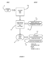
- FIG. 8 is a functional block diagram of a preferred embodiment of the system and method of the present invention.
- FIG. 9 depicts the sequence of steps of the manual event scoring portion of the system of the present invention.
- FIG. 10 depicts the sequence of steps of the automated event scoring portion of the system of the present invention.
- FIG. 11 is a flowchart depicting the progression of steps in the method of FIGS. 8-10 .
- FIG. 1 is a block diagram of a conventional vehicle 10 having a preferred embodiment of the system of the present invention installed therein.
- the event detector 30 A is in control of one or more event capture devices 20 that are attached to the vehicle 10 .
- the event detector 30 A communicates with the capture devices 20 via a wired or wireless interface.
- the event detector 30 A can be any of a variety of types of computing devices with the ability to execute programmed instructions, receive input from various sensors, and communicate with one or more internal or external event capture devices 20 and other external devices (not shown).
- the detector 30 A may utilize software, hardware and/or firmware in a variety of combinations to execute the instructions of the disclosed method.
- An example general purpose computing device that may be employed as all or a portion of an event detector 30 A is later described in connection with the discussion related to FIG. 3 , hereinbelow.
- an example general purpose wireless communication device that may be employed as all or a portion of an event detector 30 A is later described in connection with the discussion related to FIG. 4 hereinbelow.
- the event detector 30 A When the event detector 30 A identifies an event, the event detector 30 A instructs the one or more event capture devices 20 to record pre-event data, during the event data, and post-event data that is then provided to the event detector 30 A and stored in the data storage area 35 .
- the event capture devices 20 constantly save data in a buffer memory, which allows the system to actually obtain data that was first-recorded (into a buffer memory) prior to the event itself.
- Events may comprise a variety of situations, including automobile accidents, reckless driving, rough driving, or any other type of stationary or moving occurrence that the owner of a vehicle 10 may desire to know about, and is more fully described below in connection with other drawing figures.
- the vehicle 10 may have a plurality of event capture devices 20 placed in various locations around the vehicle 10 .
- An event capture device 20 may comprise a video camera, still camera, microphone, and other types of data capture devices.
- an event capture device 20 may include an accelerometer that senses changes in speed, direction, and vehicle spatial orientation. Additional sensors and/or data capture devices may also be incorporated into an event capture device 20 in order to provide a rich set of information about a detected event.
- the data storage area 35 can be any sort of internal or external, fixed or removable memory device and may include both persistent and volatile memories.
- the function of the data storage area 35 is to maintain data for long term storage and also to provide efficient and fast access to instructions for applications or modules that are executed by the event detector 30 A.
- event detector 30 A in combination with the one or more event capture devices 20 identifies an event and stores certain audio and video data along with related information about the event.
- related information may include the speed of the vehicle when the event occurred, the direction the vehicle was traveling, the location of the vehicle (e.g., from a global positioning system “GPS” sensor), and other information from sensors located in and around the vehicle or from the vehicle itself (e.g., from a data bus integral to the vehicle such as an on board diagnostic “OBD” vehicle bus).
- GPS global positioning system
- OBD on board diagnostic
- This combination of audio, video, and other data is compiled into an event that can be stored in data storage 35 onboard the vehicle for later delivery to an evaluation server. Data transfer to a remote user or server could be via a conventional wired connection, or via conventional wireless connections (such as using antennae 652 ).
- FIG. 2 we can examine some of the internal details regarding the event detector 30 A.
- FIG. 2 is a block diagram illustrating an example event detector 30 A according to an embodiment of the present invention.
- the event detector 30 A comprises an audio/video (“AV”) module 100 , a sensor module 110 , a communication module 120 , a control module 130 , and a spatial behavior module (not shown). Additional modules may also be employed to carry out the various functions of the event detector 30 A, as will be understood by those having skill in the art.
- AV audio/video
- the AV module 100 is configured to manage the audio and video input from one or more event capture devices and storage of the audio and video input.
- the sensor module 110 is configured to manage one or more sensors that can be integral to the event detector 30 A or external from the event detector 30 A.
- an accelerometer may be integral to the event detector 30 A or it may be located elsewhere in the vehicle 10 .
- the sensor module 110 may also manage other types of sensor devices such as a GPS sensor, temperature sensor, moisture sensor, and the OBD, or the like (all not shown).
- the communication module 120 is configured to manage communications between the event detector 30 A and other devices and modules. For example, the communication module 120 may handle communications between the event detector 30 A and the various event capture devices 20 . The communication module 120 may also handle communications between the event detector 30 A and a memory device, a docking station, or a server such as an evaluation server.
- the communication module 120 is configured to communicate with these various types of devices and other types of devices via a direct wire link (e.g., USB cable, firewire cable), a direct wireless link (e.g., infrared, Bluetooth, ZigBee), or a wired or any wireless network link such as a local area network (“LAN”), a wide area network (“WAN”), a wireless wide area network (“WWAN”), an IEEE 802 wireless network such as an IEEE 802.16 (“WiFi”) network, a WiMAX network, satellite network, or a cellular network.
- a direct wire link e.g., USB cable, firewire cable
- a direct wireless link e.g., infrared, Bluetooth, ZigBee
- a wired or any wireless network link such as a local area network (“LAN”), a wide area network (“WAN”), a wireless wide area network (“WWAN”), an IEEE 802 wireless network such as an IEEE 802.16 (“WiFi”) network, a WiMAX network, satellite network,
- the control module 130 is configured to control the actions or remote devices such as the one or more event capture devices.
- the control module 130 may be configured to instruct the event capture devices to capture an event and return the data to the event detector when it is informed by the sensor module 110 that certain trigger criteria have been met that identify an event.
- a pair of subsystems are new to this embodiment of the event detector 30 A, the Local Event Scoring Module 140 and the Event Data Management Module 150 . While these two modules 140 , 150 are referred to as separate subsystems, it should be understood that some or all of the functionality of each could be integrated into the Control Module 130 (or other subsystem associated with the event detector 30 A).
- the Local Event Scoring Module 140 will review the raw data streams from the individual sensors 20 (see FIG. 1 ), or the sensor module 110 , and will use one or more mathematic algorithms to calculate a local event score. While this local event score is not expected to be as robust or potentially accurate as the remote event scoring system described by the Parent Applications, it is not necessarily a requirement that this be the case, because a remote score may still be determined independent of the local score.
- the purpose for calculating the local event score is to enable the event detector 30 A to optimize the use of the data transfer bandwidth by only selectively uploading the full event data to the remote server for review/display/analysis.
- the local event scoring module 140 determines that the local event score of a particular driving event meets pre-determined criteria, it will direct the Event Data Management Module 150 to upload the appropriate data received from the sensors 20 (see FIG. 1 ) and stored locally within the vehicle (within a storage device associated with the event detector 30 A).
- the Event Data Management Module 150 may also be responsive to a remote request for additional data. For example, in circumstances where the remote user (i.e., remote to the vehicle being monitored) may receive a notice of a particular “incident” of interest, that remote user may be able to manually request audio, video or other locally-recorded data. This requested data would then be transmitted (via the communications module 120 ) to the remote user for review/analysis/display.
- This new version of event detector 30 A has the ability to reduce or at least regulate the amount of data that flows from it to the remote user(s). When fully enabled, for example, large bandwidth data streams such as video and audio data will not regularly be transmitted to the remote server unless by direction of either the Local Event Scoring Module 140 , or by manual or remote user request. This reduction of flow translates into significant cost savings, since most of these systems utilize expensive cellular telephone or satellite networks for vehicle-to-remote server communications.
- FIGS. 3 and 4 depict conventional hardware used to construct the functional elements of the Event Detector 30 A and associated subsystems.
- FIG. 3 is a block diagram of a conventional computing device 750 suitable for executing the method described hereinbelow.
- the computer system 750 may be used in conjunction with an event detector previously described with respect to FIGS. 1 and 2 , or an evaluation server, analysis station, counseling station, or supervisor station described in the Prior Applications.
- an evaluation server, analysis station, counseling station, or supervisor station described in the Prior Applications may be used, as will be clear to those skilled in the art.
- the computer system 750 preferably includes one or more processors, such as processor 752 .
- Additional processors may be provided, such as an auxiliary processor to manage input/output, an auxiliary processor to perform floating point mathematical operations, a special-purpose microprocessor having an architecture suitable for fast execution of signal processing algorithms (e.g., digital signal processor), a slave processor subordinate to the main processing system (e.g., back-end processor), an additional microprocessor or controller for dual or multiple processor systems, or a coprocessor.
- auxiliary processors may be discrete processors or may be integrated with the processor 752 .
- the processor 752 is preferably connected to a communication bus 754 .
- the communication bus 754 may include a data channel for facilitating information transfer between storage and other peripheral components of the computer system 750 .
- the communication bus 754 further may provide a set of signals used for communication with the processor 752 , including a data bus, address bus, and control bus (not shown).
- the communication bus 754 may comprise any standard or non-standard bus architecture such as, for example, bus architectures compliant with industry standard architecture (“ISA”), extended industry standard architecture (“EISA”), Micro Channel Architecture (“MCA”), peripheral component interconnect (“PCI”) local bus, mini PCI express, or standards promulgated by the Institute of Electrical and Electronics Engineers (“IEEE”) including IEEE 488 general-purpose interface bus (“GPIB”), IEEE 696/S-100, and the like.
- ISA industry standard architecture
- EISA extended industry standard architecture
- MCA Micro Channel Architecture
- PCI peripheral component interconnect
- IEEE Institute of Electrical and Electronics Engineers
- IEEE Institute of Electrical and Electronics Engineers
- GPIB general-purpose interface bus
- IEEE 696/S-100 IEEE 696/S-100
- Computer system 750 preferably includes a main memory 756 and may also include a secondary memory 758 .
- the main memory 756 provides storage of instructions and data for programs executing on the processor 752 .
- the main memory 756 is typically semiconductor-based memory such as dynamic random access memory (“DRAM”) and/or static random access memory (“SRAM”).
- DRAM dynamic random access memory
- SRAM static random access memory
- Other semiconductor-based memory types include, for example, synchronous dynamic random access memory (“SDRAM”), Rambus dynamic random access memory (“RDRAM”), ferroelectric random access memory (“FRAM”), and the like, including read only memory (“ROM”).
- SDRAM synchronous dynamic random access memory
- RDRAM Rambus dynamic random access memory
- FRAM ferroelectric random access memory
- ROM read only memory
- the secondary memory 758 may optionally include a hard disk drive 760 and/or a removable storage drive 762 , for example a floppy disk drive, a magnetic tape drive, a compact disc (“CD”) drive, a digital versatile disc (“DVD”) drive, etc.
- the removable storage drive 762 reads from and/or writes to a removable storage medium 764 in a well-known manner.
- Removable storage medium 764 may be, for example, a floppy disk, magnetic tape, CD, DVD, memory stick, USB memory device, etc.
- the removable storage medium 764 is preferably a computer readable medium having stored thereon computer executable code (i.e., software) and/or data.
- the computer software or data stored on the removable storage medium 764 is read into the computer system 750 as electrical communication signals 778 .
- secondary memory 758 may include other similar means for allowing computer programs or other data or instructions to be loaded into the computer system 750 .
- Such means may include, for example, an external storage medium 772 and an interface 770 .
- external storage medium 772 may include an external hard disk drive or an external optical drive, or an external magneto-optical drive.
- secondary memory 758 may include semiconductor-based memory such as programmable read-only memory (“PROM”), erasable programmable read-only memory (“EPROM”), electrically erasable read-only memory (“EEPROM”), or flash memory. Also included are any other removable storage units 772 and interfaces 770 , which allow software and data to be transferred from the removable storage unit 772 to the computer system 750 .
- PROM programmable read-only memory
- EPROM erasable programmable read-only memory
- EEPROM electrically erasable read-only memory
- flash memory any other removable storage units 772 and interfaces 770 , which allow software and data to be transferred from the removable storage unit 772 to the computer system 750 .
- Computer system 750 may also include a communication interface 774 .
- the communication interface 774 allows software and data to be transferred between computer system 750 and external devices (e.g., printers), networks, or information sources.
- external devices e.g., printers
- computer software or executable code may be transferred to computer system 750 from a network server via communication interface 774 .
- Examples of communication interface 774 include a modem, a network interface card (“NIC”), a communications port, a PCMCIA slot and card, an infrared interface, and an IEEE 1394 fire-wire, just to name a few.
- Communication interface 774 preferably implements industry promulgated protocol standards, such as Ethernet IEEE 802 standards, Fiber Channel, digital subscriber line (“DSL”), asynchronous digital subscriber line (“ADSL”), frame relay, asynchronous transfer mode (“ATM”), integrated digital services network (“ISDN”), personal communications services (“PCS”), transmission control protocol/Internet protocol (“TCP/IP”), serial line Internet protocol/point to point protocol (“SLIP/PPP”), and so on, but may also implement customized or non-standard interface protocols as well.
- industry promulgated protocol standards such as Ethernet IEEE 802 standards, Fiber Channel, digital subscriber line (“DSL”), asynchronous digital subscriber line (“ADSL”), frame relay, asynchronous transfer mode (“ATM”), integrated digital services network (“ISDN”), personal communications services (“PCS”), transmission control protocol/Internet protocol (“TCP/IP”), serial line Internet protocol/point to point protocol (“SLIP/PPP”), and so on, but may also implement customized or non-standard interface protocols as well.
- Communication interface 774 Software and data transferred via communication interface 774 are generally in the form of electrical communication signals 778 . These signals 778 are preferably provided to communication interface 774 via a communication channel 776 .
- Communication channel 776 carries signals 778 and can be implemented using a variety of wired or wireless communication means including wire or cable, fiber optics, conventional phone line, cellular phone link, satellite link, wireless data communication link, radio frequency (RF) link, or infrared link, just to name a few.
- RF radio frequency
- Computer executable code i.e., computer programs or software
- main memory 756 and/or the secondary memory 758 Computer programs can also be received via communication interface 774 and stored in the main memory 756 and/or the secondary memory 758 .
- Such computer programs when executed, enable the computer system 750 to perform the various functions of the present invention as previously described.
- computer readable medium is used to refer to any media used to provide computer executable code (e.g., software and computer programs) to the computer system 750 .
- Examples of these media include main memory 756 , secondary memory 758 (including hard disk drive 760 , removable storage medium 764 , and external storage medium 772 ), and any peripheral device communicatively coupled with communication interface 774 (including a network information server or other network device).
- These computer readable mediums are means for providing executable code, programming instructions, and software to the computer system 750 .
- the software may be stored on a computer readable medium and loaded into computer system 750 by way of removable storage drive 762 , interface 770 , or communication interface 774 .
- the software is loaded into the computer system 750 in the form of electrical communication signals 778 .
- the software when executed by the processor 752 , preferably causes the processor 752 to perform the inventive features and functions to be described hereinbelow.
- ASICs application specific integrated circuits
- FPGAs field programmable gate arrays
- ASICs application specific integrated circuits
- FPGAs field programmable gate arrays
- DSP digital signal processor
- a general-purpose processor can be a microprocessor, but in the alternative, the processor can be any processor, controller, microcontroller, or state machine.
- a processor can also be implemented as a combination of computing devices, for example, a combination of a DSP and a microprocessor, a plurality of microprocessors, one or more microprocessors in conjunction with a DSP core, or any other such configuration.
- a software module can reside in RAM memory, flash memory, ROM memory, EPROM memory, EEPROM memory, registers, hard disk, a removable disk, a CD-ROM, or any other form of storage medium including a network storage medium.
- An exemplary storage medium can be coupled to the processor such that the processor can read information from, and write information to, the storage medium. In the alternative, the storage medium can be integral to the processor.
- the processor and the storage medium can also reside in an ASIC.
- FIG. 4 is a block diagram of a conventional wireless communications device 650 suitable for communicating between the event detector 30 A of FIG. 2 and a remote base unit.
- the wireless communication device 650 may be used in conjunction with an event detector previously described with respect to FIGS. 1 and 2 , or an evaluation server, analysis station, counseling station, or supervisor station previously described in the Prior Applications.
- other wireless communication devices and/or architectures may also be used, as will be clear to those skilled in the art.
- wireless communication device 650 comprises an antenna 652 , a multiplexor 654 , a low noise amplifier (“LNA”) 656 , a power amplifier (“PA”) 658 , a modulation/demodulation circuit 660 , a baseband processor 662 , a speaker 664 , a microphone 666 , a central processing unit (“CPU”) 668 , a data storage area 670 , and a hardware interface 672 .
- radio frequency (“RF”) signals are transmitted and received by antenna 652 .
- Multiplexor 654 acts as a switch method to couple two or more transmit and receive paths to two or more antennae paths, coupling antenna 652 between the transmit and receive signal paths.
- received RF signals are coupled from a multiplexor 654 to LNA 656 .
- LNA 656 amplifies the received RF signal and couples the amplified signal to a demodulation portion of the modulation circuit 660 .
- modulation circuit 660 will combine a demodulator and modulator in one integrated circuit (“IC”).
- the demodulator and modulator can also be separate components.
- the demodulator strips away the RF carrier signal leaving a base-band receive audio/data signal, which is sent from the demodulator output to the baseband processor 662 .
- baseband processor 662 decodes the signal and converts it to an analog signal. Then the signal is amplified and sent to the speaker 664 .
- the baseband processor 662 also receives analog audio signals from the microphone 666 . These analog audio signals are converted to digital signals and encoded by the baseband processor 662 .
- the baseband processor 662 also codes the digital signals for transmission and generates a baseband transmit audio signal that is routed to the modulator portion of modulation circuit 660 .
- the modulator mixes the baseband transmit audio signal with an RF carrier signal generating an RF transmit signal that is routed to the power amplifier 658 .
- the power amplifier 658 amplifies the RF transmit signal and routes it to the multiplexor 654 where the signal is switched to the antenna port for transmission by antenna 652 .
- the baseband processor 662 is also communicatively coupled with the central processing unit 668 .
- the central processing unit 668 has access to a data storage area 670 .
- the central processing unit 668 is preferably configured to execute instructions (i.e., computer programs or software) that can be stored in the data storage area 670 .
- Computer programs can also be received from the baseband processor 662 and stored in the data storage area 670 or executed upon receipt. Such computer programs, when executed, enable the wireless communication device 650 to perform the various functions of the present invention as previously described.
- the term “computer readable medium” is used to refer to any media used to provide executable instructions (e.g., software and computer programs) to the wireless communication device 650 for execution by the central processing unit 668 .
- Examples of these media include the data storage area 670 , microphone 666 (via the baseband processor 662 ), antenna 652 (also via the baseband processor 662 ), and hardware interface 672 .
- These computer readable mediums are means for providing executable code, programming instructions, and software to the wireless communication device 650 .
- the executable code, programming instructions, and software when executed by the central processing unit 668 , preferably cause the central processing unit 668 to perform the inventive features and functions previously described herein.
- the firmware used by the device 650 (or CPU 668 ) can be replaced/modified/upgraded via wired or wireless network transfer.
- the central processing unit is also preferably configured to receive notifications from the hardware interface 672 when new devices are detected by the hardware interface.
- Hardware interface 672 can be a combination electromechanical detector with controlling software that communicates with the CPU 668 and interacts with new devices.
- FIG. 5 depicts how the system of the present invention handles the data from the different sensor devices.
- FIG. 5 is a block diagram depicting exemplary inputs to the event detector 30 A of FIGS. 1 and 2 , and the potential response results and destinations for detected events.
- the communications with an external evaluation server is extensively discussed in the Parent Applications, and is therefore not reproduced there, but is rather incorporated herein by reference.
- event capture devices can generate captured event data for velocity, acceleration (linear), pitch, roll, and yaw. Center of gravity and CG offset may also be used. Vehicle orientation relative to compass heading, as well as vehicle location may be included in event data. Finally, audio, video and metadata (including driver ID) will likely be included.
- the captured data 29 may be filtered by a real-time tunable raw data filter 31 before it is analyzed by the event detector 30 A to determine whether or not a driving event of note has occurred.
- the criteria for making a type of driving event of note could be user-defined for their particular reason; such events of note may or may not otherwise be considered to be risky driving events, but are otherwise of interest to the user.
- sensor data 29 As discussed above in connection with FIG. 2 , different types of sensor data 29 will be handled in different manners by the present system. For the purpose of clarity, we have here divided the sensor data 29 into two groups of data: regularly uploaded data 54 and selectively uploaded data 52 . The idea is that primarily the less bandwidth-demanding data is regularly uploaded to the remote server from the vehicle. The higher bandwidth data would be retained aboard the vehicle until it is manually requested, automatically identified as being “of interest”, or for periodic record-keeping purposes (which very well may be accomplished via wired or wireless connection while the vehicle is under a maintenance status).
- the video and audio data and telemetry data have been included within the selectively uploaded data 52 .
- Driver ID is also included within the selectively uploaded data 52 , since the objective evidence of the driver's identity (such as a video clip) may not be obtained until commanded as such by the event detector 30 A (such as right after the local event scoring module 140 (see FIG. 2 )) determines that an event of interest has transpired. At that point, any remote user receiving the video and audio data would most likely be very interested in confirming the identity of the driver (since the goal would be to transfer the data 52 when there is a vehicular crash or near miss).
- One factor that might be used to determine whether or not an “event of interest” has transpired is related to the nature of the forces (i.e., of the accelerometer) being sensed. Certain forces (e.g., shock) have been identified as being automatically “of interest,” even without any real onboard analysis of the entire set of data streams being analyzed.
- the regularly uploaded data 54 is handled as discussed in the prior applications, that is, initial filtering 31 may be performed on the data in order to reduce false event occurrences.
- the event detector 30 A will convey the regularly uploaded data 54 as described in the Parent Applications (incorporated herein by reference) and identified as the prior data output options 41 (summarized below in connection with FIG. 6 ).
- the local event scoring module 140 (see FIG. 2 ) will conduct local analysis 56 of the regularly uploaded data 54 in order to calculate a local event score. If the local event score so determines, the selectively uploaded event data 52 will be transmitted to remote storage 34 (at the remote server) for display/review/analysis (e.g., scoring) remote to the vehicle.
- a remote request 58 (from a remote user or system) will also trigger the data 52 to be uploaded to remote storage 34 for remote display and analysis 36 A.
- those transfer paths responsive to the local analysis 56 or remote request 58 are identified by dashed lines.
- the depicted classifications of data as being part of the “selectively uploaded” data 52 versus the “regularly uploaded” data 54 is only one possible arrangement.
- the system may send one or more designated persons a message (email, SMS, etc.) that will include a brief alert message that there has been an “incident” in a vehicle (or more than one vehicle).
- the user may then be able to select a “hyperlink” that will act as a user request to download the selected data from the system (either the vehicle or the central remote server or related assemblies).
- the data being downloaded in response to the user request would normally be video and/or audio data, but it could also include other data points or data streams, such as vehicle location coordinates (e.g., via GPS), incident type or classification (e.g., “crash,” “vehicle flipover,” “excessive speed,” etc.).
- vehicle location coordinates e.g., via GPS
- incident type or classification e.g., “crash,” “vehicle flipover,” “excessive speed,” etc.
- the user's request after being alerted of the incident may either be serviced by the remote server system or by the vehicle-borne system.
- the selectively uploaded data 52 may not be uploaded to the server until after a user has requested it.
- the alert message to the user (which usually would not include any large bandwidth, selectively uploaded data 52 ) may have more than one data upload option.
- the user may be given the options of: (a) uploading a short video clip including vehicle GPS location and speed; (b) uploading actively streaming video and audio directly from the vehicle; or (c) uploading current video/audio data plus similar data from some period of time prior to the incident having occurred.
- FIG. 6 is a block diagram of the prior data output options 41 available to the event detector 30 A (see FIG. 5 ).
- captured event data can be output in accordance with a number of options 41 , including placement in a local storage repository 35 . Transmission to a remote storage repository 34 may also occur, either automatically, or in response to user request. Furthermore, there may be a blend of local storage and partial transmission to remote storage 34 .
- Remote analysis 36 can be conducted on remotely stored data as desired by the system custodian or other authorized individuals. Of course, it is also expected that a certain quantity of data that is initially stored locally and/or remotely will ultimately be deleted 32 in order to conserve space in the respective data repositories.
- a remote archive data repository 38 is a potential destination for some of the data initially held in the local or remote data repositories 35 , 34 .
- These storage options 41 are operationally distinct from those discussed above in connection with FIG. 5 , but they generally will use the identical hardware—these two drawing figures are organized as shown in order to highlight the operational distinctions between the handling of the selectively uploaded data 52 and the regularly uploaded data 54 (see FIG. 5 ).
- FIG. 7 we can examine the method that the system of the present invention executes.
- FIG. 7 is a block diagram depicting the preferred steps of the selectively automatic event scoring method 50 of the present invention.
- the sensor data 20 is received by the event detector 30 A (potentially after filtration of the raw data). This data is buffered and stored for more prolonged periods in local storage 35 aboard the vehicle.
- a remote (“go-get”) request 702 is received by the event detector 30 A, the requested data will be uploaded from the event detector 30 A to the remote server for storage/analysis/display 704 .
- local auto scoring 706 is activated, the system will generate a local event score 708 . That local event score is then compared to a series of previously stored event score values (typically in a database) 710 , to generate an automatic determination of whether or not a serious driving event (e.g., a vehicular crash) has occurred 712 . If the local event scoring module 140 (see FIG. 2 ) determines that a serious event has occurred, then the selectively-uploaded data 52 (see FIG. 5 ) is uploaded to the remote server 704 . As discussed above, if there is no remote request 700 or local score-triggered upload 706 , the data will be handled according to prior data output options 702 .
- FIG. 8 is a functional block diagram of a preferred embodiment of the system and method 60 of the present invention.
- the event detector (aboard the vehicle) for local analysis 56 .
- the event detector transmits event data (ODB, video, audio, metadata, etc.) to the manual event scoring module 62 and/or the automated event scoring module 64 .
- Manual event scoring 62 is conducted by human review of the data “clips” received from the event detector. Generally this is at a workstation at a location that is remote from the vehicle, although it may also be conducted within the vehicle itself once the event “clips” have been viewed and reviewed. Furthermore, in certain embodiments, event data “clips” can be reviewed and scored by a human being at virtually any portable computing device, including cellular telephones and the like.
- Automated event scoring 64 can also be conducted within a computing device that is remote to the reporting vehicle, as well as at virtually any portable computing device. What is most likely, however, is that the event detector itself includes the automated scoring module within the same system (and perhaps physical housing) as the other functional modules of the event detector (see FIGS. 1 and 2 ). Scoring the events “on the fly” within the actual vehicle being monitored optimizes the overall driver risk assessment system in several ways. First, as will be discussed further below, each event has been scored before any data has been transmitted from the vehicle to a remote location—this reduces wireless transmission bandwidth by allowing the system to act and react to the type and severity of events from the earliest possible place in the data analysis stream, so as to handle the event data transmission in a custom manner each and every time.
- FIG. 9 depicts the sequence of steps of the manual event scoring portion 62 of the system of the present invention.
- the sensors feed data 29 to the event detector.
- an “event” is considered to have happened.
- This “trigger” results in the sensor data 29 being saved by the event detector (e.g., transferred from memory buffer to a longer-term memory storage area) 160 .
- the event detector then applies an analytical method to the triggered sensor data (or “clips”) 122 to immediately predict what type of risky driving event has occurred (e.g., crash, excessive braking, hard cornering).
- the output of step 122 typically includes an event alert 124 that could be in a variety of forms (as discussed in the parent of this CIP Application).
- an event alert 124 could be in a variety of forms (as discussed in the parent of this CIP Application).
- the customer could receive an instant message, email or other notification of the event's occurrence.
- there could be local notification (i.e., within the vehicle) of the event occurrence, just to insure that the driver is aware that the system has acted.
- the event detector will also assign a predicted risk identification to the event.
- the risk is only considered to be predicted because all of the analytical study has been done by the event detector and/or sensors as a result of “triggers.”
- sensor data-based triggers will reliably detect “events” from the raw (or filtered) sensor data
- the problem is that there is a tendency to substantially “over-report” events. That is to say that not every “event” that is predicted to have occurred actually turns out to be risky driving behavior once it is reviewed in detail. If there is too much over-reporting, the user tends to be desensitized, with the result being the ignoring of events reported by the system. It is for this reason that the system has historically included manual event scoring.
- the risk identification 126 assigned to the event is very critical. It is one of a series of discrete “nodes” or identity results that is reached after the sensor data is analyzed by the event detector.
- the nodes or ID's are the result of the processing and analyzing of mass quantities of actual driving events (or suspected driving events).
- a predicted event is in actuality confirmed as an actual risky driving event in a significant portion of cases. This is evidenced in that the “tree” of nodes through which the sensor data is processed is of non-trivial value, and is actually quite successful at filtering out real sensor data (really combinations of data) to arrive at a defined type of risk that is represented by the predicted event.
- risk ID we do not mean a sequential identifier intended to point to a single discrete “event,” but rather we are speaking of assigning a pre-existing risk identification (one of a group of possible risk identities) to the event data triggered by the sensors and/or event detector.
- Manual event scoring 62 is conducted by human review of the predicted events generated by the event detector/sensors.
- the human reviewer will review each and every “clip” of data recording the “event,” including accelerometer, GPS, OBD, video, audio and others according to the invention as previously described.
- the human reviewer/scorer will view the actual video of the driver and potential exterior area surrounding the vehicle, just prior to, during, and just after the predicted event has occurred. This video review virtually transforms the human reviewer into a witness to the incident. As such, there is an extremely high level of confidence that the reviewer will certify (or decertify) the predicted event as a true event.
- each “type” of event e.g., hard braking, swerving, etc.
- a severity quotient e.g., not all hard braking events are of the same severity and therefore riskiness
- the manual scoring of an event creates a series of outputs.
- An event score is produced 170 . That score is delivered, perhaps along with some or all of the sensor data (e.g., video) to the user 132 .
- the system compares the result of the manual scoring to the predicted scoring result, and the data representing the confidence level of the risk identity prediction is updated to include this final score 136 .
- the output data includes the vehicle type (which affects the version of risk prediction system choice), the version of risk prediction package that generated the predicted event, the identity of the final risk as scored, and the accuracy of the predicted risk vs the final scored risk (accuracy both a percent accurate to identity, as well as the severity of the scored vs predicted risk).
- FIG. 10 depicts the sequence followed by the new method.
- FIG. 10 depicts the sequence of steps of the automated event scoring portion 64 of the system of the present invention.
- the initial steps of the automatic scoring sequence are essentially the same as the manual scoring sequence previously described.
- the sensors data 29 is supplied to the event detector in response to a sensor or event detector trigger.
- the triggered event data 160 is analyzed by the event detector and risk and type of event are predicted 122 .
- An event alert 124 is initiated (which might be only an internal “system” alert).
- a risk identity I.D. is assigned to the event 126 .
- the automatic event scoring module examines the predicted event risk and generates an event score 180 , and delivers it to the user 132 in essentially the same fashion (and with the same options) as the manual event scoring method.
- the automated event scoring module is re-calibrated with updated confidence data from new manually-scored events 138 .
- the reliability/accuracy rate of the event identification and the severity is updated.
- risk confidence data 66 is updated.
- the data records contained within the risk confidence data repository tend to be very small in size because these are essentially control parameters used in the automatic scoring module.
- the event detector in the average installation will establish communications at least once a day with the remote sewer system in order to verify operability, and at times to transfer event data “clips” from the event detector to the remote system. At that time, it is a simple matter for the newest version of the risk confidence data to be uploaded and implemented in the automatic scoring module at the vehicle. Alternatively, where the automatic scoring module is a part of the remote server system, updates may be on a more regular basis.
- FIG. 11 is a flowchart depicting the progression of steps in the method 60 of FIGS. 8-10 .
- the event detector 30 B receives data from each of its associated sensors 20 while the vehicle is active (powered on). On an ongoing basis, the event detector 30 B will buffer data locally, and will also store buffered data from all sensors 20 in local storage 35 upon receipt of data exceeding a trigger threshold (or an actual trigger signal) from one or more sensors 20 .
- the event detector 30 B will analyze the data from the sensors 20 by applying a pre-established set of data analytics (e.g., a decision tree) to the data.
- a pre-established set of data analytics e.g., a decision tree
- This tree is the result of a long-term study of vehicular sensors and their responses during thousands of miles of monitored driving. Each vehicle type has, in effect, its own particular decision tree; updated versions of the trees are released with historical and/or equipment or software upgrades.
- the data from any triggered event passing through the risk prediction “tree” will arrive at a “node.”
- the node is the far end of the decision tree for that particular combination of values emanating from the sensor data 20 . It should be understood that raw sensor data may undergo statistical or other analysis in order to be usable by the risk prediction tree.
- rate of change of a particular data value may be the operative characteristic used to navigate the tree, rather than the raw sensor value itself.
- the node at which the data ultimately “exits” the tree has been previously labeled herein as the “Risk I.D.”
- This Risk I.D. while expected to be a much more accurate prediction of a risky driving event than is the sensor triggered event identification, will still require downstream processing in order to obtain acceptable levels of reliability in the identification of risky driving events.
- the subsequent systematic actions will depend upon the type of scoring that has been elected. While not typical, it is possible that no scoring is desired 142 . Under such circumstances, which might be diagnostic in nature, the data/reporting options 144 would generally include the transfer of sensor/event data to a remote data storage repository for detailed analysis.
- the video (and accompanying data) related to the “event” is reviewed at a data review station (generally remote to the vehicle, but also could be local) by a human reviewer 146 .
- the human review of the video and other data will result in an event score 148 .
- the output from the manual review of the event will include: vehicle type (e.g., bus, passenger car, dump truck, etc.), the version of the risk prediction decision tree, the Risk Identification (or node) identified by the Event Detector 30 B, and a point value (on a predetermined scale) that assesses the riskiness of the driver's behavior during the event. It after manual human review, the scored event meets the appropriate criteria, the event is reported to the user 132 .
- Another byproduct of the manual human event review of the data of predicted events is to update 136 the risk confidence data repository 66 .
- the results of each manually-scored event will be applied to the existing risk confidence data 66 .
- Each “node” or Risk I.D. has a profile associated with it. The profile includes the vehicle type, the risk prediction version, and the risk I.D.
- the statistical reliability of the appropriate risk I.D. profile is assessed. That is to say that there is an ongoing reliability analysis that indicates how often the human reviewer actually identified that there was a risky driving event (as a percentage of all times that this particular risk I.D. was identified), as well as what the typical or expected severity of the risk has historically been (and therefore is expected to be).
- the risk confidence data 66 is then periodically updated 138 within the automated scoring module (whether local or remote to the vehicle). These regular updates are labeled as calibrations because they actually serve to further filter out non-events from the predicted events based on the confidence level in the predicted risk I.D. For example, if, historically, a particular risk I.D. (e.g., unsafe lane change in a dump truck) has only very infrequently been verified as being risky by manual human review, then it would be statistically irresponsible to automatically treat such a risk I.D. as an actual driving event.
- a particular risk I.D. e.g., unsafe lane change in a dump truck
- the automatic scoring module will not normally deliver an event report to the user, since the likelihood that there was a real risky driving event (or one of substantial severity) is too low to be reliable.
- this score reliability filtration of events is adjustable so that the full range of system sensitivities is available.
- risk confidence data 66 (as the automatic scoring module has been most recently calibrated) for the predicted risk I.D. is applied 152 , and if there is sufficient reliability (in frequency and severity) as pre-set in the system, the user is delivered an event report 132 .
- the event report options will generally match those options available for manual event scoring (since in both cases there is a high level of confidence that risky driving has occurred). It should be noticed that automatic scoring does not in actuality assign a score to a particular risk I.D. Instead, the automatic scoring module will determine whether the risk I.D. identified by the event detector 30 B has a high enough expectation of reliability (as being risky), after which the automatic event scoring module confirms that a risky driving event has occurred. Automatic scoring, then, is more like noise filtration (i.e., elimination of non-events from user reports) than it is like manual human scoring (where a predicted risk I.D. is given a severity score by the human reviewer).
- the autoscore profiles are updated once per day, and then reviewed within twenty-four (24) hours to insure that the update does not create a problem or error.
- the profile update will be conducted in the evening when the vehicle is generally parked (and cellular telephone rates are reduced).
- this update periodicity can be adjusted in order to match the usage pattern of the vehicles and drivers of a particular fleet. Updates can also be selectively (manually) imposed by the system administrator, such as when system-wide upgrades are implemented.
Abstract
Description
Claims (17)
Priority Applications (3)
| Application Number | Priority Date | Filing Date | Title |
|---|---|---|---|
| US12/814,117 US8508353B2 (en) | 2009-01-26 | 2010-06-11 | Driver risk assessment system and method having calibrating automatic event scoring |
| US13/923,130 US9317980B2 (en) | 2006-05-09 | 2013-06-20 | Driver risk assessment system and method having calibrating automatic event scoring |
| US15/017,518 US9978191B2 (en) | 2006-05-09 | 2016-02-05 | Driver risk assessment system and method having calibrating automatic event scoring |
Applications Claiming Priority (3)
| Application Number | Priority Date | Filing Date | Title |
|---|---|---|---|
| US12/359,787 US8269617B2 (en) | 2009-01-26 | 2009-01-26 | Method and system for tuning the effect of vehicle characteristics on risk prediction |
| US12/691,639 US8849501B2 (en) | 2009-01-26 | 2010-01-21 | Driver risk assessment system and method employing selectively automatic event scoring |
| US12/814,117 US8508353B2 (en) | 2009-01-26 | 2010-06-11 | Driver risk assessment system and method having calibrating automatic event scoring |
Related Parent Applications (1)
| Application Number | Title | Priority Date | Filing Date |
|---|---|---|---|
| US12/359,787 Continuation-In-Part US8269617B2 (en) | 2006-05-08 | 2009-01-26 | Method and system for tuning the effect of vehicle characteristics on risk prediction |
Related Child Applications (1)
| Application Number | Title | Priority Date | Filing Date |
|---|---|---|---|
| US13/923,130 Continuation US9317980B2 (en) | 2006-05-09 | 2013-06-20 | Driver risk assessment system and method having calibrating automatic event scoring |
Publications (2)
| Publication Number | Publication Date |
|---|---|
| US20100250021A1 US20100250021A1 (en) | 2010-09-30 |
| US8508353B2 true US8508353B2 (en) | 2013-08-13 |
Family
ID=42785250
Family Applications (3)
| Application Number | Title | Priority Date | Filing Date |
|---|---|---|---|
| US12/814,117 Active 2030-06-15 US8508353B2 (en) | 2006-05-09 | 2010-06-11 | Driver risk assessment system and method having calibrating automatic event scoring |
| US13/923,130 Active US9317980B2 (en) | 2006-05-09 | 2013-06-20 | Driver risk assessment system and method having calibrating automatic event scoring |
| US15/017,518 Active US9978191B2 (en) | 2006-05-09 | 2016-02-05 | Driver risk assessment system and method having calibrating automatic event scoring |
Family Applications After (2)
| Application Number | Title | Priority Date | Filing Date |
|---|---|---|---|
| US13/923,130 Active US9317980B2 (en) | 2006-05-09 | 2013-06-20 | Driver risk assessment system and method having calibrating automatic event scoring |
| US15/017,518 Active US9978191B2 (en) | 2006-05-09 | 2016-02-05 | Driver risk assessment system and method having calibrating automatic event scoring |
Country Status (1)
| Country | Link |
|---|---|
| US (3) | US8508353B2 (en) |
Cited By (75)
| Publication number | Priority date | Publication date | Assignee | Title |
|---|---|---|---|---|
| US20100191411A1 (en) * | 2009-01-26 | 2010-07-29 | Bryon Cook | Driver Risk Assessment System and Method Employing Selectively Automatic Event Scoring |
| US20130218604A1 (en) * | 2012-02-21 | 2013-08-22 | Elwha Llc | Systems and methods for insurance based upon monitored characteristics of a collision detection system |
| US20140257870A1 (en) * | 2013-03-10 | 2014-09-11 | State Farm Mutual Automobile Insurance Company | Determining Driving Patterns from On-Board Vehicle Sensor Data |
| US8868288B2 (en) | 2006-11-09 | 2014-10-21 | Smartdrive Systems, Inc. | Vehicle exception event management systems |
| US8880279B2 (en) | 2005-12-08 | 2014-11-04 | Smartdrive Systems, Inc. | Memory management in event recording systems |
| US8892310B1 (en) | 2014-02-21 | 2014-11-18 | Smartdrive Systems, Inc. | System and method to detect execution of driving maneuvers |
| US8989959B2 (en) | 2006-11-07 | 2015-03-24 | Smartdrive Systems, Inc. | Vehicle operator performance history recording, scoring and reporting systems |
| US9000903B2 (en) | 2012-07-09 | 2015-04-07 | Elwha Llc | Systems and methods for vehicle monitoring |
| US9159371B2 (en) | 2013-08-14 | 2015-10-13 | Digital Ally, Inc. | Forensic video recording with presence detection |
| US9165469B2 (en) | 2012-07-09 | 2015-10-20 | Elwha Llc | Systems and methods for coordinating sensor operation for collision detection |
| US9183679B2 (en) | 2007-05-08 | 2015-11-10 | Smartdrive Systems, Inc. | Distributed vehicle event recorder systems having a portable memory data transfer system |
| US9189899B2 (en) | 2009-01-26 | 2015-11-17 | Lytx, Inc. | Method and system for tuning the effect of vehicle characteristics on risk prediction |
| US9201842B2 (en) | 2006-03-16 | 2015-12-01 | Smartdrive Systems, Inc. | Vehicle event recorder systems and networks having integrated cellular wireless communications systems |
| US9230442B2 (en) | 2013-07-31 | 2016-01-05 | Elwha Llc | Systems and methods for adaptive vehicle sensing systems |
| US9245391B2 (en) | 2009-01-26 | 2016-01-26 | Lytx, Inc. | Driver risk assessment system and method employing automated driver log |
| US9253452B2 (en) | 2013-08-14 | 2016-02-02 | Digital Ally, Inc. | Computer program, method, and system for managing multiple data recording devices |
| US20160046297A1 (en) * | 2013-03-28 | 2016-02-18 | Honda Motor Co., Ltd. | Driving evaluation system, electronic device, driving evaluation method, and program |
| US9269268B2 (en) | 2013-07-31 | 2016-02-23 | Elwha Llc | Systems and methods for adaptive vehicle sensing systems |
| US9317980B2 (en) | 2006-05-09 | 2016-04-19 | Lytx, Inc. | Driver risk assessment system and method having calibrating automatic event scoring |
| US9402060B2 (en) | 2006-03-16 | 2016-07-26 | Smartdrive Systems, Inc. | Vehicle event recorders with integrated web server |
| US9501878B2 (en) | 2013-10-16 | 2016-11-22 | Smartdrive Systems, Inc. | Vehicle event playback apparatus and methods |
| US9554080B2 (en) | 2006-11-07 | 2017-01-24 | Smartdrive Systems, Inc. | Power management systems for automotive video event recorders |
| US9558667B2 (en) | 2012-07-09 | 2017-01-31 | Elwha Llc | Systems and methods for cooperative collision detection |
| US9610955B2 (en) | 2013-11-11 | 2017-04-04 | Smartdrive Systems, Inc. | Vehicle fuel consumption monitor and feedback systems |
| US9626879B2 (en) | 2013-09-05 | 2017-04-18 | Crown Equipment Corporation | Dynamic operator behavior analyzer |
| US9633318B2 (en) | 2005-12-08 | 2017-04-25 | Smartdrive Systems, Inc. | Vehicle event recorder systems |
| US9639804B1 (en) | 2016-03-22 | 2017-05-02 | Smartdrive Systems, Inc. | System and method to determine responsiveness of a driver of a vehicle to feedback regarding driving behaviors |
| US9663127B2 (en) | 2014-10-28 | 2017-05-30 | Smartdrive Systems, Inc. | Rail vehicle event detection and recording system |
| US9712730B2 (en) | 2012-09-28 | 2017-07-18 | Digital Ally, Inc. | Portable video and imaging system |
| US9714037B2 (en) | 2014-08-18 | 2017-07-25 | Trimble Navigation Limited | Detection of driver behaviors using in-vehicle systems and methods |
| US9728228B2 (en) | 2012-08-10 | 2017-08-08 | Smartdrive Systems, Inc. | Vehicle event playback apparatus and methods |
| US9776632B2 (en) | 2013-07-31 | 2017-10-03 | Elwha Llc | Systems and methods for adaptive vehicle sensing systems |
| US9841259B2 (en) | 2015-05-26 | 2017-12-12 | Digital Ally, Inc. | Wirelessly conducted electronic weapon |
| US9958228B2 (en) | 2013-04-01 | 2018-05-01 | Yardarm Technologies, Inc. | Telematics sensors and camera activation in connection with firearm activity |
| US9979813B2 (en) | 2016-10-04 | 2018-05-22 | Allstate Solutions Private Limited | Mobile device communication access and hands-free device activation |
| US10013883B2 (en) | 2015-06-22 | 2018-07-03 | Digital Ally, Inc. | Tracking and analysis of drivers within a fleet of vehicles |
| US10075681B2 (en) | 2013-08-14 | 2018-09-11 | Digital Ally, Inc. | Dual lens camera unit |
| US10161746B2 (en) | 2014-08-18 | 2018-12-25 | Trimble Navigation Limited | Systems and methods for cargo management |
| US10192277B2 (en) | 2015-07-14 | 2019-01-29 | Axon Enterprise, Inc. | Systems and methods for generating an audit trail for auditable devices |
| US10204159B2 (en) | 2015-08-21 | 2019-02-12 | Trimble Navigation Limited | On-demand system and method for retrieving video from a commercial vehicle |
| US10264111B2 (en) | 2016-10-04 | 2019-04-16 | Allstate Solutions Private Limited | Mobile device communication access and hands-free device activation |
| US10271015B2 (en) | 2008-10-30 | 2019-04-23 | Digital Ally, Inc. | Multi-functional remote monitoring system |
| US10272848B2 (en) | 2012-09-28 | 2019-04-30 | Digital Ally, Inc. | Mobile video and imaging system |
| US10274338B2 (en) | 2016-12-11 | 2019-04-30 | International Business Machines Corporation | Risk situations for vehicle occupants based on data provided by vehicle sensors and contextual information |
| TWI660276B (en) * | 2017-12-05 | 2019-05-21 | 財團法人資訊工業策進會 | System and method for applying user profile model to score |
| US10346925B2 (en) * | 2016-08-12 | 2019-07-09 | Swiss Reinsurance Company Ltd. | Telematics system with vehicle embedded telematics devices (OEM line fitted) for score-driven, automated risk-transfer and corresponding method thereof |
| US10360636B1 (en) | 2012-08-01 | 2019-07-23 | Allstate Insurance Company | System for capturing passenger and trip data for a taxi vehicle |
| US10390732B2 (en) | 2013-08-14 | 2019-08-27 | Digital Ally, Inc. | Breath analyzer, system, and computer program for authenticating, preserving, and presenting breath analysis data |
| US10409621B2 (en) | 2014-10-20 | 2019-09-10 | Taser International, Inc. | Systems and methods for distributed control |
| US10486709B1 (en) | 2019-01-16 | 2019-11-26 | Ford Global Technologies, Llc | Vehicle data snapshot for fleet |
| US10521675B2 (en) | 2016-09-19 | 2019-12-31 | Digital Ally, Inc. | Systems and methods of legibly capturing vehicle markings |
| US10594991B1 (en) | 2018-01-09 | 2020-03-17 | Wm Intellectual Property Holdings, Llc | System and method for managing service and non-service related activities associated with a waste collection, disposal and/or recycling vehicle |
| US10686976B2 (en) | 2014-08-18 | 2020-06-16 | Trimble Inc. | System and method for modifying onboard event detection and/or image capture strategy using external source data |
| US10699347B1 (en) | 2016-02-24 | 2020-06-30 | Allstate Insurance Company | Polynomial risk maps |
| US10730439B2 (en) | 2005-09-16 | 2020-08-04 | Digital Ally, Inc. | Vehicle-mounted video system with distributed processing |
| US10764542B2 (en) | 2014-12-15 | 2020-09-01 | Yardarm Technologies, Inc. | Camera activation in response to firearm activity |
| US10810504B1 (en) | 2015-03-11 | 2020-10-20 | State Farm Mutual Automobile Insurance Company | Route scoring for assessing or predicting driving performance |
| US10904474B2 (en) | 2016-02-05 | 2021-01-26 | Digital Ally, Inc. | Comprehensive video collection and storage |
| US10911725B2 (en) | 2017-03-09 | 2021-02-02 | Digital Ally, Inc. | System for automatically triggering a recording |
| US10930093B2 (en) | 2015-04-01 | 2021-02-23 | Smartdrive Systems, Inc. | Vehicle event recording system and method |
| US10955252B2 (en) | 2018-04-03 | 2021-03-23 | International Business Machines Corporation | Road-condition based routing system |
| US11017476B1 (en) * | 2015-11-17 | 2021-05-25 | Uipco, Llc | Telematics system and method for accident detection and notification |
| US11024137B2 (en) | 2018-08-08 | 2021-06-01 | Digital Ally, Inc. | Remote video triggering and tagging |
| US11030890B2 (en) | 2018-05-03 | 2021-06-08 | International Business Machines Corporation | Local driver pattern based notifications |
| US11069257B2 (en) | 2014-11-13 | 2021-07-20 | Smartdrive Systems, Inc. | System and method for detecting a vehicle event and generating review criteria |
| US11169797B2 (en) | 2019-02-22 | 2021-11-09 | Ford Global Technologies, Llc | Vehicle controller configuration backup and restoration using data snapshots |
| US11295218B2 (en) | 2016-10-17 | 2022-04-05 | Allstate Solutions Private Limited | Partitioning sensor based data to generate driving pattern map |
| US11307042B2 (en) | 2015-09-24 | 2022-04-19 | Allstate Insurance Company | Three-dimensional risk maps |
| US11373536B1 (en) | 2021-03-09 | 2022-06-28 | Wm Intellectual Property Holdings, L.L.C. | System and method for customer and/or container discovery based on GPS drive path and parcel data analysis for a waste / recycling service vehicle |
| US11386362B1 (en) | 2020-12-16 | 2022-07-12 | Wm Intellectual Property Holdings, L.L.C. | System and method for optimizing waste / recycling collection and delivery routes for service vehicles |
| US11475417B1 (en) | 2019-08-23 | 2022-10-18 | Wm Intellectual Property Holdings, Llc | System and method for auditing the fill status of a customer waste container by a waste services provider during performance of a waste service activity |
| US11488118B1 (en) | 2021-03-16 | 2022-11-01 | Wm Intellectual Property Holdings, L.L.C. | System and method for auditing overages and contamination for a customer waste container by a waste services provider during performance of a waste service activity |
| US20230219521A1 (en) * | 2014-07-21 | 2023-07-13 | State Farm Mutual Automobile Insurance Company | Methods of facilitating emergency assistance |
| US11928693B1 (en) | 2021-03-09 | 2024-03-12 | Wm Intellectual Property Holdings, L.L.C. | System and method for customer and/or container discovery based on GPS drive path analysis for a waste / recycling service vehicle |
| US11950017B2 (en) | 2022-05-17 | 2024-04-02 | Digital Ally, Inc. | Redundant mobile video recording |
Families Citing this family (80)
| Publication number | Priority date | Publication date | Assignee | Title |
|---|---|---|---|---|
| US10185455B2 (en) | 2012-10-04 | 2019-01-22 | Zonar Systems, Inc. | Mobile computing device for fleet telematics |
| US9563869B2 (en) | 2010-09-14 | 2017-02-07 | Zonar Systems, Inc. | Automatic incorporation of vehicle data into documents captured at a vehicle using a mobile computing device |
| US20130164715A1 (en) | 2011-12-24 | 2013-06-27 | Zonar Systems, Inc. | Using social networking to improve driver performance based on industry sharing of driver performance data |
| US20130164713A1 (en) | 2011-12-23 | 2013-06-27 | Zonar Systems, Inc. | Method and apparatus for gps based slope determination, real-time vehicle mass determination, and vehicle efficiency analysis |
| US10056008B1 (en) | 2006-06-20 | 2018-08-21 | Zonar Systems, Inc. | Using telematics data including position data and vehicle analytics to train drivers to improve efficiency of vehicle use |
| US11482058B2 (en) | 2008-09-09 | 2022-10-25 | United Parcel Service Of America, Inc. | Systems and methods for utilizing telematics data to improve fleet management operations |
| US8416067B2 (en) | 2008-09-09 | 2013-04-09 | United Parcel Service Of America, Inc. | Systems and methods for utilizing telematics data to improve fleet management operations |
| US9386447B2 (en) | 2009-07-21 | 2016-07-05 | Scott Ferrill Tibbitts | Method and system for controlling a mobile communication device |
| WO2011011544A1 (en) | 2009-07-21 | 2011-01-27 | Scott Ferrill Tibbitts | Method and system for controlling a mobile communication device in a moving vehicle |
| US9615213B2 (en) | 2009-07-21 | 2017-04-04 | Katasi Llc | Method and system for controlling and modifying driving behaviors |
| US9785702B1 (en) * | 2010-04-23 | 2017-10-10 | Numerex Corp. | Analytical scoring engine for remote device data |
| US9107565B2 (en) * | 2010-08-16 | 2015-08-18 | Fujitsu Limited | Identifying an event occurrence from sensor data streams |
| US20120115413A1 (en) * | 2010-11-10 | 2012-05-10 | Ipcomm Llc | Method for Suspending Transmission and Reception of Text Messages and Phone Calls while Drivin |
| US9527515B2 (en) | 2011-12-23 | 2016-12-27 | Zonar Systems, Inc. | Vehicle performance based on analysis of drive data |
| US8731736B2 (en) * | 2011-02-22 | 2014-05-20 | Honda Motor Co., Ltd. | System and method for reducing driving skill atrophy |
| US9208626B2 (en) | 2011-03-31 | 2015-12-08 | United Parcel Service Of America, Inc. | Systems and methods for segmenting operational data |
| US9953468B2 (en) | 2011-03-31 | 2018-04-24 | United Parcel Service Of America, Inc. | Segmenting operational data |
| DE112012003061T5 (en) | 2011-07-21 | 2014-05-15 | Bendix Commercial Vehicle Systems, Llc | Vehicle Fleet Management System and Methods to Control and Improve Driver Performance in Fleet Vehicles |
| US8996234B1 (en) | 2011-10-11 | 2015-03-31 | Lytx, Inc. | Driver performance determination based on geolocation |
| US9298575B2 (en) * | 2011-10-12 | 2016-03-29 | Lytx, Inc. | Drive event capturing based on geolocation |
| US8915738B2 (en) | 2012-01-24 | 2014-12-23 | Toyota Motor Engineering & Manufacturing North America, Inc. | Driver quality assessment for driver education |
| US20130261939A1 (en) | 2012-04-01 | 2013-10-03 | Zonar Systems, Inc. | Method and apparatus for matching vehicle ecu programming to current vehicle operating conditions |
| US8676428B2 (en) * | 2012-04-17 | 2014-03-18 | Lytx, Inc. | Server request for downloaded information from a vehicle-based monitor |
| US9240079B2 (en) | 2012-04-17 | 2016-01-19 | Lytx, Inc. | Triggering a specialized data collection mode |
| US8688380B2 (en) * | 2012-04-23 | 2014-04-01 | Geotab Inc. | Even driven data acquisition switch |
| US8731768B2 (en) | 2012-05-22 | 2014-05-20 | Hartford Fire Insurance Company | System and method to provide telematics data on a map display |
| US9424696B2 (en) | 2012-10-04 | 2016-08-23 | Zonar Systems, Inc. | Virtual trainer for in vehicle driver coaching and to collect metrics to improve driver performance |
| US9344683B1 (en) | 2012-11-28 | 2016-05-17 | Lytx, Inc. | Capturing driving risk based on vehicle state and automatic detection of a state of a location |
| US9141582B1 (en) | 2012-12-19 | 2015-09-22 | Allstate Insurance Company | Driving trip and pattern analysis |
| US9081650B1 (en) | 2012-12-19 | 2015-07-14 | Allstate Insurance Company | Traffic based driving analysis |
| US9524269B1 (en) | 2012-12-19 | 2016-12-20 | Allstate Insurance Company | Driving event data analysis |
| US9141995B1 (en) | 2012-12-19 | 2015-09-22 | Allstate Insurance Company | Driving trip and pattern analysis |
| US9104535B1 (en) | 2012-12-19 | 2015-08-11 | Allstate Insurance Company | Traffic based driving analysis |
| US9535878B1 (en) | 2012-12-19 | 2017-01-03 | Allstate Insurance Company | Driving event data analysis |
| US9761063B2 (en) | 2013-01-08 | 2017-09-12 | Lytx, Inc. | Server determined bandwidth saving in transmission of events |
| US9053516B2 (en) | 2013-07-15 | 2015-06-09 | Jeffrey Stempora | Risk assessment using portable devices |
| US10169821B2 (en) * | 2013-09-20 | 2019-01-01 | Elwha Llc | Systems and methods for insurance based upon status of vehicle software |
| US9424607B2 (en) | 2013-09-20 | 2016-08-23 | Elwha Llc | Systems and methods for insurance based upon status of vehicle software |
| US9349228B2 (en) | 2013-10-23 | 2016-05-24 | Trimble Navigation Limited | Driver scorecard system and method |
| US9805521B1 (en) | 2013-12-03 | 2017-10-31 | United Parcel Service Of America, Inc. | Systems and methods for assessing turns made by a vehicle |
| IN2014MU00452A (en) * | 2014-02-07 | 2015-09-25 | Tata Consultancy Services Ltd | |
| US9511778B1 (en) * | 2014-02-12 | 2016-12-06 | XL Hybrids | Controlling transmissions of vehicle operation information |
| US9754425B1 (en) | 2014-02-21 | 2017-09-05 | Allstate Insurance Company | Vehicle telematics and account management |
| US10373257B1 (en) | 2014-02-21 | 2019-08-06 | Arity International Limited | Vehicle telematics and account management |
| CN106463005B (en) * | 2014-04-24 | 2019-07-12 | 梅塔系统股份公司 | Remote information monitoring system for vehicle |
| US9428195B1 (en) * | 2014-07-24 | 2016-08-30 | Lytx, Inc. | Back-end event risk assessment with historical coaching profiles |
| WO2016028933A1 (en) * | 2014-08-19 | 2016-02-25 | Stempora Jeffrey | System for determining an underwriting risk, risk score, or price of insurance using sensor information |
| US10521749B2 (en) | 2014-12-26 | 2019-12-31 | Panasonic Intellectual Property Corporation Of America | Risk information processing method and server device |
| WO2016116646A1 (en) * | 2015-01-20 | 2016-07-28 | Olba Labs, S.L. | System and method for automatically detecting vehicle accidents |
| US10578465B2 (en) * | 2015-02-03 | 2020-03-03 | Infineon Technologies Ag | Sensor bus system and unit with internal event verification |
| JP6193912B2 (en) * | 2015-04-24 | 2017-09-06 | 株式会社パイ・アール | Drive recorder |
| US20160334225A1 (en) | 2015-05-11 | 2016-11-17 | United Parcel Service Of America, Inc. | Determining street segment headings |
| US9892573B1 (en) | 2015-10-14 | 2018-02-13 | Allstate Insurance Company | Driver performance ratings |
| EP3469437A4 (en) | 2016-06-13 | 2020-03-25 | Xevo Inc. | Method and system for providing auto space management using virtuous cycle |
| CN106774289A (en) * | 2016-11-21 | 2017-05-31 | 百度在线网络技术(北京)有限公司 | A kind of driving model switching method and apparatus of automatic driving vehicle |
| US10015462B1 (en) * | 2016-12-15 | 2018-07-03 | Lytx, Inc. | Risk dependent variable compression rate for event storage |
| AU2017382448B2 (en) | 2016-12-22 | 2023-07-13 | Xevo Inc. | Method and system for providing interactive parking management via artificial intelligence analytic (AIA) services using cloud network |
| WO2018139871A1 (en) * | 2017-01-27 | 2018-08-02 | Samsung Electronics Co., Ltd. | Method, electronic apparatus, and system of sharing vehicle performance information among vehicles |
| US11055942B2 (en) * | 2017-08-01 | 2021-07-06 | The Chamberlain Group, Inc. | System and method for facilitating access to a secured area |
| WO2019028039A1 (en) * | 2017-08-01 | 2019-02-07 | The Chamberlain Group, Inc. | System for facilitating access to a secured area |
| CN108198271B (en) * | 2017-12-26 | 2020-09-18 | 卡斯柯信号有限公司 | Train operation risk dynamic analysis method based on SEUM (remote intelligent management) utilization vehicle-mounted computer |
| US10423886B2 (en) | 2017-12-29 | 2019-09-24 | Forward Thinking Systems, LLC | Electronic logs with compliance support and prediction |
| US11328219B2 (en) * | 2018-04-12 | 2022-05-10 | Baidu Usa Llc | System and method for training a machine learning model deployed on a simulation platform |
| EP3614717B1 (en) * | 2018-08-22 | 2023-08-16 | Rohde & Schwarz GmbH & Co. KG | Radio signal recorder, radio signal analyzer and radio signal analyzing method |
| US11178180B2 (en) * | 2018-11-01 | 2021-11-16 | EMC IP Holding Company LLC | Risk analysis and access activity categorization across multiple data structures for use in network security mechanisms |
| CN109829621B (en) * | 2018-12-28 | 2024-01-09 | 深圳市元征科技股份有限公司 | Network appointment vehicle dispatching method and device |
| FR3095404B1 (en) * | 2019-04-25 | 2021-10-22 | Transdev Group | Electronic communication device, monitoring device, supervision installation, associated communication method and computer program |
| FR3095405B1 (en) * | 2019-04-25 | 2021-05-07 | Transdev Group | Electronic communication device, monitoring device, supervision installation, associated communication method and computer program |
| JP7389144B2 (en) * | 2019-06-07 | 2023-11-29 | エヌイーシー ラボラトリーズ ヨーロッパ ゲーエムベーハー | Methods and systems for dynamic event identification and dissemination |
| US11302125B2 (en) | 2019-07-30 | 2022-04-12 | Bendix Commercial Vehicle Systems Llc | Information-enhanced off-vehicle event identification |
| US10754893B1 (en) * | 2019-09-09 | 2020-08-25 | Forward Thinking Systems, LLC | Providing access to vehicle videos |
| DE102019127730B4 (en) * | 2019-10-15 | 2023-04-27 | Bayerische Motoren Werke Aktiengesellschaft | System for image stabilization of a display in a vehicle, vehicle, communication system, method and computer-readable storage medium |
| US20210125423A1 (en) * | 2019-10-29 | 2021-04-29 | Allstate Insurance Company | Processing System for Dynamic Collison Verification & Sensor Selection |
| WO2021168387A1 (en) * | 2020-02-21 | 2021-08-26 | Calamp Corp. | Technologies for driver behavior assessment |
| US11550337B2 (en) | 2020-06-16 | 2023-01-10 | Geotab Inc. | Data capture trigger configuration for asset tracking |
| US11640577B2 (en) | 2020-06-16 | 2023-05-02 | Geotab Inc. | Data capture instructions for asset tracking |
| CN111950238B (en) * | 2020-07-30 | 2023-06-13 | 禾多科技(北京)有限公司 | Automatic driving fault scoring table generation method and device and electronic equipment |
| CN112270114B (en) * | 2020-11-24 | 2022-04-29 | 武汉理工大学 | Vehicle personalized risk behavior identification method |
| RU2760043C1 (en) * | 2020-12-30 | 2021-11-22 | Сергей Васильевич Сумароков | System and method for assessment of driver behavior |
| CN112885084B (en) * | 2021-01-15 | 2022-02-18 | 南京理工大学 | Tunnel traffic incident detection method and system |
Citations (58)
| Publication number | Priority date | Publication date | Assignee | Title |
|---|---|---|---|---|
| US4281354A (en) | 1978-05-19 | 1981-07-28 | Raffaele Conte | Apparatus for magnetic recording of casual events relating to movable means |
| US4718685A (en) | 1985-12-09 | 1988-01-12 | Nissan Motor Co., Ltd. | Model solving type vehicle steering control system with parameter identification |
| US5140436A (en) | 1989-11-02 | 1992-08-18 | Eastman Kodak Company | Pre-event/post-event recording in a solid state fast frame recorder |
| DE4416991A1 (en) | 1994-05-13 | 1995-11-16 | Pietzsch Ag | Warning HGV driver against overturning in negotiation of curve |
| US5497419A (en) | 1994-04-19 | 1996-03-05 | Prima Facie, Inc. | Method and apparatus for recording sensor data |
| US5546191A (en) | 1992-02-25 | 1996-08-13 | Mitsubishi Denki Kabushiki Kaisha | Recording and reproducing apparatus |
| US5574424A (en) | 1994-05-09 | 1996-11-12 | Nguyen; Duc M. | Anti-car jacking/theft device |
| US5600775A (en) | 1994-08-26 | 1997-02-04 | Emotion, Inc. | Method and apparatus for annotating full motion video and other indexed data structures |
| US5689442A (en) | 1995-03-22 | 1997-11-18 | Witness Systems, Inc. | Event surveillance system |
| US5815093A (en) | 1996-07-26 | 1998-09-29 | Lextron Systems, Inc. | Computerized vehicle log |
| US5825284A (en) | 1996-12-10 | 1998-10-20 | Rollover Operations, Llc | System and method for the detection of vehicle rollover conditions |
| US6141611A (en) | 1998-12-01 | 2000-10-31 | John J. Mackey | Mobile vehicle accident data system |
| US6163338A (en) | 1997-12-11 | 2000-12-19 | Johnson; Dan | Apparatus and method for recapture of realtime events |
| US20010005804A1 (en) | 1998-02-09 | 2001-06-28 | I-Witness, Inc. | Vehicle event data recorder including validation of output |
| US6389340B1 (en) | 1998-02-09 | 2002-05-14 | Gary A. Rayner | Vehicle data recorder |
| US6405132B1 (en) | 1997-10-22 | 2002-06-11 | Intelligent Technologies International, Inc. | Accident avoidance system |
| US20020111725A1 (en) * | 2000-07-17 | 2002-08-15 | Burge John R. | Method and apparatus for risk-related use of vehicle communication system data |
| US6449540B1 (en) | 1998-02-09 | 2002-09-10 | I-Witness, Inc. | Vehicle operator performance recorder triggered by detection of external waves |
| US20020163532A1 (en) | 2001-03-30 | 2002-11-07 | Koninklijke Philips Electronics N.V. | Streaming video bookmarks |
| US20030080878A1 (en) | 2001-10-30 | 2003-05-01 | Kirmuss Charles Bruno | Event-based vehicle image capture |
| US6575902B1 (en) | 1999-01-27 | 2003-06-10 | Compumedics Limited | Vigilance monitoring system |
| US20040039503A1 (en) * | 2002-08-26 | 2004-02-26 | International Business Machines Corporation | Secure logging of vehicle data |
| US20040054513A1 (en) | 1998-11-23 | 2004-03-18 | Nestor, Inc. | Traffic violation detection at an intersection employing a virtual violation line |
| US20040103010A1 (en) | 2002-11-27 | 2004-05-27 | Stephan Wahlbin | Computerized method and system for estimating an effect on liability of the speed of vehicles in an accident and time and distance traveled by the vehicles |
| US20040153362A1 (en) | 1996-01-29 | 2004-08-05 | Progressive Casualty Insurance Company | Monitoring system for determining and communicating a cost of insurance |
| US20040236474A1 (en) * | 2003-02-27 | 2004-11-25 | Mahesh Chowdhary | Vehicle management system |
| US20050073585A1 (en) | 2003-09-19 | 2005-04-07 | Alphatech, Inc. | Tracking systems and methods |
| US20050137757A1 (en) | 2003-05-06 | 2005-06-23 | Joseph Phelan | Motor vehicle operating data collection and analysis |
| US20050166258A1 (en) | 2002-02-08 | 2005-07-28 | Alexander Vasilevsky | Centralized digital video recording system with bookmarking and playback from multiple locations |
| US20060053038A1 (en) * | 2004-09-08 | 2006-03-09 | Warren Gregory S | Calculation of driver score based on vehicle operation |
| US20060103127A1 (en) | 2004-11-16 | 2006-05-18 | Arvin Technology, Llc | Module structure for a vehicle |
| US20060212195A1 (en) | 2005-03-15 | 2006-09-21 | Veith Gregory W | Vehicle data recorder and telematic device |
| US20070001831A1 (en) * | 2005-06-09 | 2007-01-04 | Drive Diagnostics Ltd. | System and method for displaying a driving profile |
| US20070027583A1 (en) | 2003-07-07 | 2007-02-01 | Sensomatix Ltd. | Traffic information system |
| US7209833B2 (en) | 2004-01-19 | 2007-04-24 | Denso Corporation | Collision possibility determination device |
| US20070124332A1 (en) | 2005-11-29 | 2007-05-31 | General Electric Company | Method and apparatus for remote detection and control of data recording systems on moving systems |
| US20070135979A1 (en) * | 2005-12-09 | 2007-06-14 | Smartdrive Systems Inc | Vehicle event recorder systems |
| US20070136078A1 (en) | 2005-12-08 | 2007-06-14 | Smartdrive Systems Inc. | Vehicle event recorder systems |
| US20070150140A1 (en) | 2005-12-28 | 2007-06-28 | Seymour Shafer B | Incident alert and information gathering method and system |
| US20070173994A1 (en) | 2006-01-26 | 2007-07-26 | Noboru Kubo | Vehicle behavior analysis system |
| EP1818873A1 (en) | 2006-02-09 | 2007-08-15 | Sap Ag | Transmission of sensor data on geographical navigation data |
| US20070216521A1 (en) | 2006-02-28 | 2007-09-20 | Guensler Randall L | Real-time traffic citation probability display system and method |
| US20070241874A1 (en) | 2006-04-17 | 2007-10-18 | Okpysh Stephen L | Braking intensity light |
| US20070257815A1 (en) * | 2006-05-08 | 2007-11-08 | Drivecam, Inc. | System and method for taking risk out of driving |
| US20070260677A1 (en) | 2006-03-17 | 2007-11-08 | Viddler, Inc. | Methods and systems for displaying videos with overlays and tags |
| US20070257804A1 (en) | 2006-05-08 | 2007-11-08 | Drivecam, Inc. | System and Method for Reducing Driving Risk With Foresight |
| US20070257781A1 (en) | 2006-05-08 | 2007-11-08 | Drivecam, Inc. | System and Method for Identifying Non-Event Profiles |
| US20070268158A1 (en) * | 2006-05-09 | 2007-11-22 | Drivecam, Inc. | System and Method for Reducing Driving Risk With Insight |
| US20070271105A1 (en) * | 2006-05-09 | 2007-11-22 | Drivecam, Inc. | System and Method for Reducing Driving Risk With Hindsignt |
| US20070299612A1 (en) * | 2004-06-24 | 2007-12-27 | Nissan Motor Co., Ltd. | Driving assistance method and system |
| US20080167775A1 (en) * | 2004-08-27 | 2008-07-10 | Alfred Kuttenberger | Method and Device for Evaluating Driving Situations |
| US20080269978A1 (en) | 2007-04-25 | 2008-10-30 | Xora, Inc. | Method and apparatus for vehicle performance tracking |
| US20090224869A1 (en) | 2008-03-05 | 2009-09-10 | Baker Lawrence G | Vehicle Monitoring System With Power Consumption Management |
| US20100063672A1 (en) | 2008-09-11 | 2010-03-11 | Noel Wayne Anderson | Vehicle with high integrity perception system |
| US20100070175A1 (en) * | 2008-09-15 | 2010-03-18 | Navteq North America, Llc | Method and System for Providing a Realistic Environment for a Traffic Report |
| US20100085193A1 (en) * | 2008-10-06 | 2010-04-08 | International Business Machines Corporation | Recording storing, and retrieving vehicle maintenance records |
| US7702442B2 (en) | 2004-08-06 | 2010-04-20 | Honda Motor Co., Ltd. | Control device for vehicle |
| US20110077028A1 (en) * | 2009-09-29 | 2011-03-31 | Wilkes Iii Samuel M | System and Method for Integrating Smartphone Technology Into a Safety Management Platform to Improve Driver Safety |
Family Cites Families (38)
| Publication number | Priority date | Publication date | Assignee | Title |
|---|---|---|---|---|
| JP3159596B2 (en) | 1994-03-22 | 2001-04-23 | 本田技研工業株式会社 | Hydroplaning phenomenon detector |
| US8140358B1 (en) | 1996-01-29 | 2012-03-20 | Progressive Casualty Insurance Company | Vehicle monitoring system |
| US5706909A (en) | 1996-07-01 | 1998-01-13 | Bevins; Steven D. | Vehicle safety automatic braking apparatus |
| US6680694B1 (en) | 1997-08-19 | 2004-01-20 | Siemens Vdo Automotive Corporation | Vehicle information system |
| US7268700B1 (en) | 1998-01-27 | 2007-09-11 | Hoffberg Steven M | Mobile communication device |
| US6163749A (en) | 1998-06-05 | 2000-12-19 | Navigation Technologies Corp. | Method and system for scrolling a map display in a navigation application |
| DE10022173C2 (en) | 2000-05-06 | 2003-07-03 | Conti Temic Microelectronic | Procedure for triggering occupant protection devices |
| AU8002001A (en) | 2000-07-20 | 2002-02-05 | Viraf S Kapadia | System and method for transportation vehicle monitoring, feedback and control |
| US7190960B2 (en) | 2002-06-14 | 2007-03-13 | Cingular Wireless Ii, Llc | System for providing location-based services in a wireless network, such as modifying locating privileges among individuals and managing lists of individuals associated with such privileges |
| SE531334C2 (en) | 2003-01-30 | 2009-02-24 | Facility Parking Europ Ab | Vehicle ID |
| JP3890062B2 (en) | 2003-05-16 | 2007-03-07 | 富士通株式会社 | Alarm system, alarm control device, and alarm control program |
| US7826948B2 (en) | 2004-10-15 | 2010-11-02 | Ford Global Technologies | Vehicle loading based vehicle dynamic and safety related characteristic adjusting system |
| US8075484B2 (en) * | 2005-03-02 | 2011-12-13 | Martin Moore-Ede | Systems and methods for assessing equipment operator fatigue and using fatigue-risk-informed safety-performance-based systems and methods to replace or supplement prescriptive work-rest regulations |
| US20070043487A1 (en) | 2005-08-19 | 2007-02-22 | Snap-On Incorporated | Method and system for providing vehicle-service alerts to a vehicle technician |
| US8269617B2 (en) | 2009-01-26 | 2012-09-18 | Drivecam, Inc. | Method and system for tuning the effect of vehicle characteristics on risk prediction |
| US8849501B2 (en) | 2009-01-26 | 2014-09-30 | Lytx, Inc. | Driver risk assessment system and method employing selectively automatic event scoring |
| US8508353B2 (en) | 2009-01-26 | 2013-08-13 | Drivecam, Inc. | Driver risk assessment system and method having calibrating automatic event scoring |
| AU2007271741B2 (en) | 2006-07-06 | 2013-01-31 | Biorics Nv | Real-time monitoring and control of physical and arousal status of individual organisms |
| US7940250B2 (en) | 2006-09-06 | 2011-05-10 | Apple Inc. | Web-clip widgets on a portable multifunction device |
| US8989959B2 (en) * | 2006-11-07 | 2015-03-24 | Smartdrive Systems, Inc. | Vehicle operator performance history recording, scoring and reporting systems |
| US20080234920A1 (en) | 2007-03-21 | 2008-09-25 | Nokia Corporation | Remote Traffic Coordination and Control |
| US7839292B2 (en) | 2007-04-11 | 2010-11-23 | Nec Laboratories America, Inc. | Real-time driving danger level prediction |
| US20100312464A1 (en) | 2007-05-01 | 2010-12-09 | Chicke Fitzgerald | Advice engine delivering personalized search results and customized roadtrip plans |
| US8146136B1 (en) * | 2007-06-15 | 2012-03-27 | Amazon Technologies, Inc. | Automated acceptance or rejection of consumer correction submissions |
| EP2065688B1 (en) | 2007-11-27 | 2012-04-18 | Elektrobit Automotive GmbH | Technique for detecting shifted cargo |
| US20100153146A1 (en) | 2008-12-11 | 2010-06-17 | International Business Machines Corporation | Generating Generalized Risk Cohorts |
| KR101039312B1 (en) | 2008-07-11 | 2011-06-08 | 삼성전자주식회사 | Navigation system and method for providing navigation system using mobile terminal |
| US8600741B2 (en) | 2008-08-20 | 2013-12-03 | General Motors Llc | Method of using microphone characteristics to optimize speech recognition performance |
| US8854199B2 (en) | 2009-01-26 | 2014-10-07 | Lytx, Inc. | Driver risk assessment system and method employing automated driver log |
| TW201035581A (en) | 2009-03-27 | 2010-10-01 | Ind Tech Res Inst | Space detecting apparatus, vehicle and control method thereof |
| US9615213B2 (en) * | 2009-07-21 | 2017-04-04 | Katasi Llc | Method and system for controlling and modifying driving behaviors |
| US8604925B2 (en) | 2009-10-23 | 2013-12-10 | Globalstar, Inc. | Simplex personal and asset tracker |
| US20110112995A1 (en) * | 2009-10-28 | 2011-05-12 | Industrial Technology Research Institute | Systems and methods for organizing collective social intelligence information using an organic object data model |
| US20110213628A1 (en) * | 2009-12-31 | 2011-09-01 | Peak David F | Systems and methods for providing a safety score associated with a user location |
| US9558520B2 (en) * | 2009-12-31 | 2017-01-31 | Hartford Fire Insurance Company | System and method for geocoded insurance processing using mobile devices |
| US20110257882A1 (en) | 2010-04-15 | 2011-10-20 | Mcburney Paul W | Road map feedback server for tightly coupled gps and dead reckoning vehicle navigation |
| US20120190001A1 (en) * | 2011-01-25 | 2012-07-26 | Hemisphere Centre for Mental Health & Wellness Inc. | Automated cognitive testing methods and applications therefor |
| US11429651B2 (en) * | 2013-03-14 | 2022-08-30 | International Business Machines Corporation | Document provenance scoring based on changes between document versions |
-
2010
- 2010-06-11 US US12/814,117 patent/US8508353B2/en active Active
-
2013
- 2013-06-20 US US13/923,130 patent/US9317980B2/en active Active
-
2016
- 2016-02-05 US US15/017,518 patent/US9978191B2/en active Active
Patent Citations (62)
| Publication number | Priority date | Publication date | Assignee | Title |
|---|---|---|---|---|
| US4281354A (en) | 1978-05-19 | 1981-07-28 | Raffaele Conte | Apparatus for magnetic recording of casual events relating to movable means |
| US4718685A (en) | 1985-12-09 | 1988-01-12 | Nissan Motor Co., Ltd. | Model solving type vehicle steering control system with parameter identification |
| US5140436A (en) | 1989-11-02 | 1992-08-18 | Eastman Kodak Company | Pre-event/post-event recording in a solid state fast frame recorder |
| US5546191A (en) | 1992-02-25 | 1996-08-13 | Mitsubishi Denki Kabushiki Kaisha | Recording and reproducing apparatus |
| US5497419A (en) | 1994-04-19 | 1996-03-05 | Prima Facie, Inc. | Method and apparatus for recording sensor data |
| US5574424A (en) | 1994-05-09 | 1996-11-12 | Nguyen; Duc M. | Anti-car jacking/theft device |
| DE4416991A1 (en) | 1994-05-13 | 1995-11-16 | Pietzsch Ag | Warning HGV driver against overturning in negotiation of curve |
| US5600775A (en) | 1994-08-26 | 1997-02-04 | Emotion, Inc. | Method and apparatus for annotating full motion video and other indexed data structures |
| US5689442A (en) | 1995-03-22 | 1997-11-18 | Witness Systems, Inc. | Event surveillance system |
| US20040153362A1 (en) | 1996-01-29 | 2004-08-05 | Progressive Casualty Insurance Company | Monitoring system for determining and communicating a cost of insurance |
| US5815093A (en) | 1996-07-26 | 1998-09-29 | Lextron Systems, Inc. | Computerized vehicle log |
| US5825284A (en) | 1996-12-10 | 1998-10-20 | Rollover Operations, Llc | System and method for the detection of vehicle rollover conditions |
| US6405132B1 (en) | 1997-10-22 | 2002-06-11 | Intelligent Technologies International, Inc. | Accident avoidance system |
| US6163338A (en) | 1997-12-11 | 2000-12-19 | Johnson; Dan | Apparatus and method for recapture of realtime events |
| US20010005804A1 (en) | 1998-02-09 | 2001-06-28 | I-Witness, Inc. | Vehicle event data recorder including validation of output |
| US6389340B1 (en) | 1998-02-09 | 2002-05-14 | Gary A. Rayner | Vehicle data recorder |
| US6449540B1 (en) | 1998-02-09 | 2002-09-10 | I-Witness, Inc. | Vehicle operator performance recorder triggered by detection of external waves |
| US6718239B2 (en) | 1998-02-09 | 2004-04-06 | I-Witness, Inc. | Vehicle event data recorder including validation of output |
| US20040054513A1 (en) | 1998-11-23 | 2004-03-18 | Nestor, Inc. | Traffic violation detection at an intersection employing a virtual violation line |
| US6141611A (en) | 1998-12-01 | 2000-10-31 | John J. Mackey | Mobile vehicle accident data system |
| US6575902B1 (en) | 1999-01-27 | 2003-06-10 | Compumedics Limited | Vigilance monitoring system |
| US20020111725A1 (en) * | 2000-07-17 | 2002-08-15 | Burge John R. | Method and apparatus for risk-related use of vehicle communication system data |
| US20020163532A1 (en) | 2001-03-30 | 2002-11-07 | Koninklijke Philips Electronics N.V. | Streaming video bookmarks |
| US20030080878A1 (en) | 2001-10-30 | 2003-05-01 | Kirmuss Charles Bruno | Event-based vehicle image capture |
| US20050166258A1 (en) | 2002-02-08 | 2005-07-28 | Alexander Vasilevsky | Centralized digital video recording system with bookmarking and playback from multiple locations |
| US20040039503A1 (en) * | 2002-08-26 | 2004-02-26 | International Business Machines Corporation | Secure logging of vehicle data |
| US20040103010A1 (en) | 2002-11-27 | 2004-05-27 | Stephan Wahlbin | Computerized method and system for estimating an effect on liability of the speed of vehicles in an accident and time and distance traveled by the vehicles |
| US20040236474A1 (en) * | 2003-02-27 | 2004-11-25 | Mahesh Chowdhary | Vehicle management system |
| US20050137757A1 (en) | 2003-05-06 | 2005-06-23 | Joseph Phelan | Motor vehicle operating data collection and analysis |
| US20070027583A1 (en) | 2003-07-07 | 2007-02-01 | Sensomatix Ltd. | Traffic information system |
| US7821421B2 (en) | 2003-07-07 | 2010-10-26 | Sensomatix Ltd. | Traffic information system |
| US20050073585A1 (en) | 2003-09-19 | 2005-04-07 | Alphatech, Inc. | Tracking systems and methods |
| US7209833B2 (en) | 2004-01-19 | 2007-04-24 | Denso Corporation | Collision possibility determination device |
| US20070299612A1 (en) * | 2004-06-24 | 2007-12-27 | Nissan Motor Co., Ltd. | Driving assistance method and system |
| US7702442B2 (en) | 2004-08-06 | 2010-04-20 | Honda Motor Co., Ltd. | Control device for vehicle |
| US20080167775A1 (en) * | 2004-08-27 | 2008-07-10 | Alfred Kuttenberger | Method and Device for Evaluating Driving Situations |
| US20060053038A1 (en) * | 2004-09-08 | 2006-03-09 | Warren Gregory S | Calculation of driver score based on vehicle operation |
| US20060253307A1 (en) * | 2004-09-08 | 2006-11-09 | Warren Gregory S | Calculation of driver score based on vehicle operation |
| US20070027726A1 (en) * | 2004-09-08 | 2007-02-01 | Warren Gregory S | Calculation of driver score based on vehicle operation for forward looking insurance premiums |
| US20060103127A1 (en) | 2004-11-16 | 2006-05-18 | Arvin Technology, Llc | Module structure for a vehicle |
| US20060212195A1 (en) | 2005-03-15 | 2006-09-21 | Veith Gregory W | Vehicle data recorder and telematic device |
| US20070001831A1 (en) * | 2005-06-09 | 2007-01-04 | Drive Diagnostics Ltd. | System and method for displaying a driving profile |
| US20070124332A1 (en) | 2005-11-29 | 2007-05-31 | General Electric Company | Method and apparatus for remote detection and control of data recording systems on moving systems |
| US20070136078A1 (en) | 2005-12-08 | 2007-06-14 | Smartdrive Systems Inc. | Vehicle event recorder systems |
| US20070135979A1 (en) * | 2005-12-09 | 2007-06-14 | Smartdrive Systems Inc | Vehicle event recorder systems |
| US20070150140A1 (en) | 2005-12-28 | 2007-06-28 | Seymour Shafer B | Incident alert and information gathering method and system |
| US20070173994A1 (en) | 2006-01-26 | 2007-07-26 | Noboru Kubo | Vehicle behavior analysis system |
| EP1818873A1 (en) | 2006-02-09 | 2007-08-15 | Sap Ag | Transmission of sensor data on geographical navigation data |
| US20070216521A1 (en) | 2006-02-28 | 2007-09-20 | Guensler Randall L | Real-time traffic citation probability display system and method |
| US20070260677A1 (en) | 2006-03-17 | 2007-11-08 | Viddler, Inc. | Methods and systems for displaying videos with overlays and tags |
| US20070241874A1 (en) | 2006-04-17 | 2007-10-18 | Okpysh Stephen L | Braking intensity light |
| US20070257781A1 (en) | 2006-05-08 | 2007-11-08 | Drivecam, Inc. | System and Method for Identifying Non-Event Profiles |
| US20070257804A1 (en) | 2006-05-08 | 2007-11-08 | Drivecam, Inc. | System and Method for Reducing Driving Risk With Foresight |
| US20070257815A1 (en) * | 2006-05-08 | 2007-11-08 | Drivecam, Inc. | System and method for taking risk out of driving |
| US20070271105A1 (en) * | 2006-05-09 | 2007-11-22 | Drivecam, Inc. | System and Method for Reducing Driving Risk With Hindsignt |
| US20070268158A1 (en) * | 2006-05-09 | 2007-11-22 | Drivecam, Inc. | System and Method for Reducing Driving Risk With Insight |
| US20080269978A1 (en) | 2007-04-25 | 2008-10-30 | Xora, Inc. | Method and apparatus for vehicle performance tracking |
| US20090224869A1 (en) | 2008-03-05 | 2009-09-10 | Baker Lawrence G | Vehicle Monitoring System With Power Consumption Management |
| US20100063672A1 (en) | 2008-09-11 | 2010-03-11 | Noel Wayne Anderson | Vehicle with high integrity perception system |
| US20100070175A1 (en) * | 2008-09-15 | 2010-03-18 | Navteq North America, Llc | Method and System for Providing a Realistic Environment for a Traffic Report |
| US20100085193A1 (en) * | 2008-10-06 | 2010-04-08 | International Business Machines Corporation | Recording storing, and retrieving vehicle maintenance records |
| US20110077028A1 (en) * | 2009-09-29 | 2011-03-31 | Wilkes Iii Samuel M | System and Method for Integrating Smartphone Technology Into a Safety Management Platform to Improve Driver Safety |
Non-Patent Citations (90)
| Title |
|---|
| "Ambulance Companies Use Video Technology to Improve Driving Behavior", Ambulance Industry Journal, Spring 2003. |
| "Amended Complaint for Patent Infringement, Trade Secret Misappropriation, Unfair Competition and Conversion" in DriveCam, Inc. v. SmartDrive Systems, Inc., Case No. 3:11-CV-00997-H-RBB, for the Southern District of California, Document 34, filed Oct. 20, 2011, pp. 1-15. |
| "Answer to Amended Complaint; Counterclaims; and Demand for Jury Trial" in DriveCam, Inc. v. SmartDrive Systems, Inc., Case No. 3:11-CV-00997 H (RBB), for the Southern District of California, Document 47, filed Dec. 13, 2011, pp. 1-15. |
| "DriveCam Driving Feedback System", Mar. 15, 2004. |
| "DriveCam, Inc's Disclosure of Proposed Constructions and Extrinsic Evidence Pursuant to Patent L.R. 4.1.a & 4.1.b" in DriveCam, Inc. v. SmartDrive Systems, Inc., Case No. 3:11-CV-00997-H-RBB, for the Southern District of California. Nov. 8, 2011. |
| "DriveCam, Inc's Disclosure of Responsive Constructions and Extrinsic Evidence Pursuant to Patent L.R. 4.1.c & 4.1d" in DriveCam, Inc. v. SmartDrive Systems, Inc., Case No. 3:11-CV-00997-H-RBB, for the Southern District of California. Nov. 15, 2011. |
| "DriveCam-Illuminator Data Sheet", Oct. 2, 2004. |
| "DriveCam—Illuminator Data Sheet", Oct. 2, 2004. |
| "DriveCam's Disclosure of Asserted Claims and Preliminary Infringement Contentions" in DriveCam, Inc. v. SmartDrive Systems, Inc., Case No. 3:11-CV-00997-H-RBB, for the Southern District of California. Aug. 19, 2011. |
| "Driver Feedback System", Jun. 12, 2001. |
| "First Amended Answer to Amended Complaint and First Amended Counterclaims; and Demand for Jury Trial" in DriveCam, Inc. v. SmartDrive Systems, Inc., Case No. 3:11-CV-00997 H (RBB), for the Southern District of California, Document 53, filed Dec. 20, 2011, pp. 1-48. |
| "First Amended Answer to Amended Complaint and First Amended Counterclaims; and Demand for Jury Trial" in DriveCam, Inc. v. SmartDrive Systems, Inc., Case No. 3:11-CV-00997 H (RBB), for the Southern District of California, Document 55, filed Jan. 3, 2012, pp. 86-103. |
| "HindSight v4.0 Users Guide", DriveCam Video Systems, Apr. 25, 2005. |
| "Interior Camera Data Sheet", Oct. 26, 2001. |
| "Joint Claim Construction Chart" in DriveCam, Inc. v. SmartDrive Systems, Inc., Case No. 11-CV-0997-H (RBB), for the Southern District of California, Document 43, filed Dec. 1, 2011, pp. 1-2. |
| "Joint Claim Construction Worksheet" in DriveCam, Inc. v. SmartDrive Systems, Inc., Case No. 3:11-CV-00997 H (RBB), for the Southern District of California, Document 44, filed Dec. 1, 2011, pp. 1-2. |
| "Passenger Transportation Mode Brochure", May 2, 2005. |
| "Preliminary Claim Construction and Identification of Extrinsic Evidence of Defendant/Counterclaimant SmartDriveSystems, Inc." in DriveCam, Inc. v. SmartDrive Systems, Inc., Case No. 3:11-CV-00997-H (RBB), for the Southern District of California. Nov. 8, 2011. |
| "Responsive Claim Construction and Identification of Extrinsic Evidence of Defendant/Counterclaimant SmartDrive Systems, Inc." in DriveCam, Inc. v. SmartDrive Systems, Inc., Case No. 3:11-CV-00997-H (RBB), for the Southern District of California. Nov. 15, 2011. |
| "Supplement to DriveCam's Disclosure of Asserted Claims and Preliminary Infringement Contentions" in DriveCam, Inc. v. SmartDrive Systems, Inc., Case No. 3:11-CV-00997-H-RBB, for the Southern District of California. Oct. 14, 2011. |
| "The DriveCam", Nov. 6, 2002. |
| "World News Tonight", CBC Television New Program discussing teen drivers using the DriveCam Program and DriveCam Technology, Oct. 10, 2005, on PC formatted CD-R, World News Tonight.wmv, 7.02 MB, Created Jan. 12, 2011. |
| "World News Tonight", PBS Television New Program discussing teen drivers using the DriveCam Program and DriveCam Technology, Oct. 10, 2005, on PC formatted CD-R, Teens Behind the Wheel.wmv, 236 MB, Created Jan. 12, 2011. |
| Adaptec published and sold its VideoOh! DVD software USB 2.0 Edition in at least Jan. 24, 2003. |
| Bill Siuru, "DriveCam Could Save You Big Bucks", Land Line Magazine, May-Jun. 2000. |
| Bill, "DriveCam-FAQ", Dec. 12, 2003. |
| Bill, "DriveCam—FAQ", Dec. 12, 2003. |
| Chris Woodyard, "Shuttles save with DriveCam", Dec. 9, 2003. |
| Dan Carr, Flash Video template: Video Presentation with Navigation, Jan. 16, 2006. |
| David Cullen, "Getting a real eyeful", Fleet Owner Magazine, Feb. 2002. |
| David Maher, "DriveCam Brochure Folder", Jun. 6, 2005. |
| David Vogeleer et al., Macromedia Flash Professional 8UNLEASHED (Sams Oct. 12, 2005) in Nov. 2005. |
| Del Lisk, "DriveCam Training Handout Ver4", Feb. 3, 2005. |
| DriveCam Extrinsic Evidence with Patent LR 4.1.a Disclosures, Nov. 8, 2011. |
| Drivecam, Inc., User's Manual for DRIVECAM Video Systems' HINDSIGHT 20/20 Software Version 4.0 (2003). |
| DriveCam, Inc.'s Infringement Contentions Exhibit A, U.S. Patent 6,389,340. Aug. 11, 2011. |
| DriveCam, Inc.'s Infringement Contentions Exhibit B, U.S. Patent 7,659,827. Aug. 19, 2011. |
| DriveCam, Inc.'s Infringement Contentions Exhibit C, U.S. Patent 7,804,426. Aug. 19, 2011. |
| DriveCam, User's Manual for DriveCam Video Systems', HindSight 20/20 Software Version 4.0, S002751-S002804(2003). |
| Gary and Sophia Rayner, Final Report for Innovations Deserving Exploratory Analysis (IDEA) Intelligent Transportation Systems (ITS) Programs' Project 84, I-Witness Black Box Recorder, San Diego, CA. Nov. 2001. |
| GE published its VCR User's Guide for Model VG4255 in 1995. |
| Glenn Oster, "HindSight 20/20 v4.0 Software Installation", 1 of 2, Jun. 20, 2003. |
| Glenn Oster, "HindSight 20/20 v4.0 Software Installation", 2 of 2, Jun. 20, 2003. |
| Glenn Oster, "Illuminator Installation", Oct. 3, 2004. |
| Hans Fantel, Video; Search Methods Make a Difference in Picking VCR's, NY Times, Aug. 13, 1989. |
| I/O Port Racing Supplies' website discloses using Traqmate's Data Acquisition with Video Overlay system in conjunction with professional driver coaching sessions (available at http://www.ioportracing.com/Merchant2/merchant. mvc?Screen=CTGY&Category-Code=coaching)., printed from site on Jan. 11, 2012. |
| I/O Port Racing Supplies' website discloses using Traqmate's Data Acquisition with Video Overlay system in conjunction with professional driver coaching sessions (available at http://www.ioportracing.com/Merchant2/merchant. mvc?Screen=CTGY&Category—Code=coaching)., printed from site on Jan. 11, 2012. |
| J. Gallagher, "Lancer Recommends Tech Tool", Insurance and Technology Magazine, Feb. 2002. |
| Jean (DriveCam vendor), "DC Data Sheet", Nov. 6, 2002. |
| Jean (DriveCam vendor), "DriveCam brochure", Nov. 6, 2002. |
| Jean (DriveCam vendor), "Feedback Data Sheet", Nov. 6, 2002. |
| Jean (DriveCam vendor), "HindSight 20-20 Data Sheet", Nov. 4, 2002. |
| Jessyca Wallace, "Analyzing and Processing DriveCam Recorded Events", Oct. 6, 2003. |
| Jessyca Wallace, "Overview of the DriveCam Program", Dec. 15, 2005. |
| Jessyca Wallace, "The DriveCam Driver Feedback System", Apr. 6, 2004. |
| Joint Claim Construction Chart, U.S. Patent No. 6,389,340, "Vehicle Data Recorder" for Case No. 3:11-CV-00997-H-RBB, Document 43-1, filed Dec. 1, 2011, pp. 1-33. |
| Joint Claim Construction Worksheet, U.S. Patent No. 6,389,340, "Vehicle Data Reporter" for Case No. 3:11-CV-00997-H-RBB, Document 44-1, filed Dec. 1, 2011, pp. 1-10. |
| Julie Stevens, "DriveCam Services", Nov. 15, 2004. |
| Julie Stevens, "Program Support Roll-Out & Monitoring", Jul. 13, 2004. |
| JVC Company of America, JVC Video Cassette Recorder HR-IP820U Instructions (1996). |
| Karen, "Downloading Options to HindSight 20120", Aug. 6, 2002. |
| Karen, "Managers Guide to the DriveCam Driving Feedback System", Jul. 30, 2002. |
| Kathy Latus (Latus Design), "Case Study-Cloud 9 Shuttle", Sep. 23, 2005. |
| Kathy Latus (Latus Design), "Case Study—Cloud 9 Shuttle", Sep. 23, 2005. |
| Kathy Latus (Latus Design), "Case Study-Lloyd Pest Control", Jul. 19, 2005. |
| Kathy Latus (Latus Design), "Case Study—Lloyd Pest Control", Jul. 19, 2005. |
| Kathy Latus (Latus Design), "Case Study-Time Warner Cable", Sep. 23, 2005. |
| Kathy Latus (Latus Design), "Case Study—Time Warner Cable", Sep. 23, 2005. |
| Lisa McKenna, "A Fly on the Windshield?", Pest Control Technology Magazine, Apr. 2003. |
| Panasonic Corporation, Video Cassette Recorder (VCR) Operating Instructions for Models No. PV-V4020/PV-V4520 (1998) (Exhibit 8) (hereinafter "Panasonic"). |
| PCT/US2010/022012, Invitation to Pay Additional Fees with Communication of Partial International Search, Jul. 21, 2010. |
| Quinn Maughan, "DriveCam Enterprise Services", Jan. 5, 2006. |
| Quinn Maughan, "DriveCam Managed Services", Jan. 5, 2006. |
| Quinn Maughan, "DriveCam Standard Edition", Jan. 5, 2006. |
| Quinn Maughan, "DriveCam Unit Installation", Jul. 21, 2005. |
| Quinn Maughan, "Enterprise Services", Apr. 17, 2006. |
| Quinn Maughan, "HindSight Installation Guide", Sep. 29, 2005. |
| Quinn Maughan, "HindSight Users Guide", Jun. 20, 2005. |
| Ronnie Rittenberry, "Eyes on the Road", Jul. 2004. |
| SmartDrives Systems, Inc.'s Production, S014246-S014255, Nov. 16, 2011. |
| Traqmate GPS Data Acquisition's Traqmate Data Acquisition with Video Overlay system was used to create a video of a driving event on Oct. 2, 2005 (available at http://www.trackvision.net/phpBB2/viewtopic.php?t=51&sid=1184fbbcbe3be5c87ffa0f2ee6e2da76), printed from site on Jan. 11, 2012. |
| U.S. Appl. No. 11/296,906, filed Dec. 8, 2005, File History. |
| U.S. Appl. No. 11/297,669, filed Dec. 8, 2005, File History. |
| U.S. Appl. No. 11/298,069, filed Dec. 9, 2005, File History. |
| U.S. Appl. No. 11/299,028, filed Dec. 9, 2005, File History. |
| U.S. Appl. No. 11/593,659, filed Nov. 7, 2006, File History. |
| U.S. Appl. No. 11/593,682, filed Nov. 7, 2006, File History. |
| U.S. Appl. No. 11/595,015, filed Nov. 9, 2006, File History. |
| U.S. Appl. No. 11/637,754, filed Dec. 13, 2006, File History. |
| U.S. Appl. No. 11/637,755, filed Dec. 13, 2006, File History. |
Cited By (163)
| Publication number | Priority date | Publication date | Assignee | Title |
|---|---|---|---|---|
| US10730439B2 (en) | 2005-09-16 | 2020-08-04 | Digital Ally, Inc. | Vehicle-mounted video system with distributed processing |
| US8880279B2 (en) | 2005-12-08 | 2014-11-04 | Smartdrive Systems, Inc. | Memory management in event recording systems |
| US9633318B2 (en) | 2005-12-08 | 2017-04-25 | Smartdrive Systems, Inc. | Vehicle event recorder systems |
| US10878646B2 (en) | 2005-12-08 | 2020-12-29 | Smartdrive Systems, Inc. | Vehicle event recorder systems |
| US9226004B1 (en) | 2005-12-08 | 2015-12-29 | Smartdrive Systems, Inc. | Memory management in event recording systems |
| US9691195B2 (en) | 2006-03-16 | 2017-06-27 | Smartdrive Systems, Inc. | Vehicle event recorder systems and networks having integrated cellular wireless communications systems |
| US9472029B2 (en) | 2006-03-16 | 2016-10-18 | Smartdrive Systems, Inc. | Vehicle event recorder systems and networks having integrated cellular wireless communications systems |
| US9402060B2 (en) | 2006-03-16 | 2016-07-26 | Smartdrive Systems, Inc. | Vehicle event recorders with integrated web server |
| US9545881B2 (en) | 2006-03-16 | 2017-01-17 | Smartdrive Systems, Inc. | Vehicle event recorder systems and networks having integrated cellular wireless communications systems |
| US10404951B2 (en) | 2006-03-16 | 2019-09-03 | Smartdrive Systems, Inc. | Vehicle event recorders with integrated web server |
| US9566910B2 (en) | 2006-03-16 | 2017-02-14 | Smartdrive Systems, Inc. | Vehicle event recorder systems and networks having integrated cellular wireless communications systems |
| US9208129B2 (en) | 2006-03-16 | 2015-12-08 | Smartdrive Systems, Inc. | Vehicle event recorder systems and networks having integrated cellular wireless communications systems |
| US9942526B2 (en) | 2006-03-16 | 2018-04-10 | Smartdrive Systems, Inc. | Vehicle event recorders with integrated web server |
| US9201842B2 (en) | 2006-03-16 | 2015-12-01 | Smartdrive Systems, Inc. | Vehicle event recorder systems and networks having integrated cellular wireless communications systems |
| US9317980B2 (en) | 2006-05-09 | 2016-04-19 | Lytx, Inc. | Driver risk assessment system and method having calibrating automatic event scoring |
| US9761067B2 (en) | 2006-11-07 | 2017-09-12 | Smartdrive Systems, Inc. | Vehicle operator performance history recording, scoring and reporting systems |
| US10053032B2 (en) | 2006-11-07 | 2018-08-21 | Smartdrive Systems, Inc. | Power management systems for automotive video event recorders |
| US10682969B2 (en) | 2006-11-07 | 2020-06-16 | Smartdrive Systems, Inc. | Power management systems for automotive video event recorders |
| US10339732B2 (en) | 2006-11-07 | 2019-07-02 | Smartdrive Systems, Inc. | Vehicle operator performance history recording, scoring and reporting systems |
| US9554080B2 (en) | 2006-11-07 | 2017-01-24 | Smartdrive Systems, Inc. | Power management systems for automotive video event recorders |
| US8989959B2 (en) | 2006-11-07 | 2015-03-24 | Smartdrive Systems, Inc. | Vehicle operator performance history recording, scoring and reporting systems |
| US9738156B2 (en) | 2006-11-09 | 2017-08-22 | Smartdrive Systems, Inc. | Vehicle exception event management systems |
| US8868288B2 (en) | 2006-11-09 | 2014-10-21 | Smartdrive Systems, Inc. | Vehicle exception event management systems |
| US11623517B2 (en) | 2006-11-09 | 2023-04-11 | SmartDriven Systems, Inc. | Vehicle exception event management systems |
| US10471828B2 (en) | 2006-11-09 | 2019-11-12 | Smartdrive Systems, Inc. | Vehicle exception event management systems |
| US9679424B2 (en) | 2007-05-08 | 2017-06-13 | Smartdrive Systems, Inc. | Distributed vehicle event recorder systems having a portable memory data transfer system |
| US9183679B2 (en) | 2007-05-08 | 2015-11-10 | Smartdrive Systems, Inc. | Distributed vehicle event recorder systems having a portable memory data transfer system |
| US10917614B2 (en) | 2008-10-30 | 2021-02-09 | Digital Ally, Inc. | Multi-functional remote monitoring system |
| US10271015B2 (en) | 2008-10-30 | 2019-04-23 | Digital Ally, Inc. | Multi-functional remote monitoring system |
| US9245391B2 (en) | 2009-01-26 | 2016-01-26 | Lytx, Inc. | Driver risk assessment system and method employing automated driver log |
| US9189899B2 (en) | 2009-01-26 | 2015-11-17 | Lytx, Inc. | Method and system for tuning the effect of vehicle characteristics on risk prediction |
| US8849501B2 (en) * | 2009-01-26 | 2014-09-30 | Lytx, Inc. | Driver risk assessment system and method employing selectively automatic event scoring |
| US20100191411A1 (en) * | 2009-01-26 | 2010-07-29 | Bryon Cook | Driver Risk Assessment System and Method Employing Selectively Automatic Event Scoring |
| US20130218604A1 (en) * | 2012-02-21 | 2013-08-22 | Elwha Llc | Systems and methods for insurance based upon monitored characteristics of a collision detection system |
| US9558667B2 (en) | 2012-07-09 | 2017-01-31 | Elwha Llc | Systems and methods for cooperative collision detection |
| US9000903B2 (en) | 2012-07-09 | 2015-04-07 | Elwha Llc | Systems and methods for vehicle monitoring |
| US9165469B2 (en) | 2012-07-09 | 2015-10-20 | Elwha Llc | Systems and methods for coordinating sensor operation for collision detection |
| US10360636B1 (en) | 2012-08-01 | 2019-07-23 | Allstate Insurance Company | System for capturing passenger and trip data for a taxi vehicle |
| US11501384B2 (en) | 2012-08-01 | 2022-11-15 | Allstate Insurance Company | System for capturing passenger and trip data for a vehicle |
| US10997669B1 (en) | 2012-08-01 | 2021-05-04 | Allstate Insurance Company | System for capturing passenger and trip data for a vehicle |
| US9728228B2 (en) | 2012-08-10 | 2017-08-08 | Smartdrive Systems, Inc. | Vehicle event playback apparatus and methods |
| US10272848B2 (en) | 2012-09-28 | 2019-04-30 | Digital Ally, Inc. | Mobile video and imaging system |
| US11667251B2 (en) | 2012-09-28 | 2023-06-06 | Digital Ally, Inc. | Portable video and imaging system |
| US9712730B2 (en) | 2012-09-28 | 2017-07-18 | Digital Ally, Inc. | Portable video and imaging system |
| US10257396B2 (en) | 2012-09-28 | 2019-04-09 | Digital Ally, Inc. | Portable video and imaging system |
| US11310399B2 (en) | 2012-09-28 | 2022-04-19 | Digital Ally, Inc. | Portable video and imaging system |
| US11315189B1 (en) | 2013-03-10 | 2022-04-26 | State Farm Mutual Automobile Insurance Company | Dynamic auto insurance policy quote creation based on tracked user data |
| US9418383B1 (en) | 2013-03-10 | 2016-08-16 | State Farm Mutual Automobile Insurance Company | System and method for determining and monitoring auto insurance incentives |
| US9779458B2 (en) | 2013-03-10 | 2017-10-03 | State Farm Mutual Automobile Insurance Company | Systems and methods for generating vehicle insurance policy data based on empirical vehicle related data |
| US9865020B1 (en) | 2013-03-10 | 2018-01-09 | State Farm Mutual Automobile Insurance Company | Systems and methods for generating vehicle insurance policy data based on empirical vehicle related data |
| US11068989B2 (en) | 2013-03-10 | 2021-07-20 | State Farm Mutual Automobile Insurance Company | Adjusting insurance policies based on common driving routes and other risk factors |
| US9646347B1 (en) | 2013-03-10 | 2017-05-09 | State Farm Mutual Automobile Insurance Company | System and method for determining and monitoring auto insurance incentives |
| US10373264B1 (en) | 2013-03-10 | 2019-08-06 | State Farm Mutual Automobile Insurance Company | Vehicle image and sound data gathering for insurance rating purposes |
| US10013719B1 (en) | 2013-03-10 | 2018-07-03 | State Farm Mutual Automobile Insurance Company | Dynamic auto insurance policy quote creation based on tracked user data |
| US20140257870A1 (en) * | 2013-03-10 | 2014-09-11 | State Farm Mutual Automobile Insurance Company | Determining Driving Patterns from On-Board Vehicle Sensor Data |
| US10387967B1 (en) | 2013-03-10 | 2019-08-20 | State Farm Mutual Automobile Insurance Company | Systems and methods for generating vehicle insurance policy data based on empirical vehicle related data |
| US9208525B2 (en) | 2013-03-10 | 2015-12-08 | State Farm Mutual Automobile Insurance Company | System and method for determining and monitoring auto insurance incentives |
| US10719879B1 (en) * | 2013-03-10 | 2020-07-21 | State Farm Mutual Automobile Insurance Company | Trip-based vehicle insurance |
| US9141996B2 (en) | 2013-03-10 | 2015-09-22 | State Farm Mutual Automobile Insurance Company | Dynamic auto insurance policy quote creation based on tracked user data |
| US11610270B2 (en) | 2013-03-10 | 2023-03-21 | State Farm Mutual Automobile Insurance Company | Adjusting insurance policies based on common driving routes and other risk factors |
| US10176530B1 (en) | 2013-03-10 | 2019-01-08 | State Farm Mutual Automobile Insurance Company | System and method for determining and monitoring auto insurance incentives |
| US20160046297A1 (en) * | 2013-03-28 | 2016-02-18 | Honda Motor Co., Ltd. | Driving evaluation system, electronic device, driving evaluation method, and program |
| US10866054B2 (en) | 2013-04-01 | 2020-12-15 | Yardarm Technologies, Inc. | Associating metadata regarding state of firearm with video stream |
| US10107583B2 (en) | 2013-04-01 | 2018-10-23 | Yardarm Technologies, Inc. | Telematics sensors and camera activation in connection with firearm activity |
| US11131522B2 (en) | 2013-04-01 | 2021-09-28 | Yardarm Technologies, Inc. | Associating metadata regarding state of firearm with data stream |
| US11466955B2 (en) | 2013-04-01 | 2022-10-11 | Yardarm Technologies, Inc. | Firearm telematics devices for monitoring status and location |
| US9958228B2 (en) | 2013-04-01 | 2018-05-01 | Yardarm Technologies, Inc. | Telematics sensors and camera activation in connection with firearm activity |
| US9269268B2 (en) | 2013-07-31 | 2016-02-23 | Elwha Llc | Systems and methods for adaptive vehicle sensing systems |
| US9230442B2 (en) | 2013-07-31 | 2016-01-05 | Elwha Llc | Systems and methods for adaptive vehicle sensing systems |
| US9776632B2 (en) | 2013-07-31 | 2017-10-03 | Elwha Llc | Systems and methods for adaptive vehicle sensing systems |
| US10074394B2 (en) | 2013-08-14 | 2018-09-11 | Digital Ally, Inc. | Computer program, method, and system for managing multiple data recording devices |
| US10390732B2 (en) | 2013-08-14 | 2019-08-27 | Digital Ally, Inc. | Breath analyzer, system, and computer program for authenticating, preserving, and presenting breath analysis data |
| US10885937B2 (en) | 2013-08-14 | 2021-01-05 | Digital Ally, Inc. | Computer program, method, and system for managing multiple data recording devices |
| US9159371B2 (en) | 2013-08-14 | 2015-10-13 | Digital Ally, Inc. | Forensic video recording with presence detection |
| US10075681B2 (en) | 2013-08-14 | 2018-09-11 | Digital Ally, Inc. | Dual lens camera unit |
| US9253452B2 (en) | 2013-08-14 | 2016-02-02 | Digital Ally, Inc. | Computer program, method, and system for managing multiple data recording devices |
| US10757378B2 (en) | 2013-08-14 | 2020-08-25 | Digital Ally, Inc. | Dual lens camera unit |
| US10964351B2 (en) | 2013-08-14 | 2021-03-30 | Digital Ally, Inc. | Forensic video recording with presence detection |
| US11694572B2 (en) | 2013-09-05 | 2023-07-04 | Crown Equipment Corporation | Dynamic operator behavior analyzer |
| US11935426B2 (en) | 2013-09-05 | 2024-03-19 | Crown Equipment Corporation | Dynamic operator behavior analyzer |
| US10991266B2 (en) | 2013-09-05 | 2021-04-27 | Crown Equipment Corporation | Dynamic operator behavior analyzer |
| US10522054B2 (en) | 2013-09-05 | 2019-12-31 | Crown Equipment Corporation | Dynamic operator behavior analyzer |
| US9626879B2 (en) | 2013-09-05 | 2017-04-18 | Crown Equipment Corporation | Dynamic operator behavior analyzer |
| US9501878B2 (en) | 2013-10-16 | 2016-11-22 | Smartdrive Systems, Inc. | Vehicle event playback apparatus and methods |
| US10818112B2 (en) | 2013-10-16 | 2020-10-27 | Smartdrive Systems, Inc. | Vehicle event playback apparatus and methods |
| US10019858B2 (en) | 2013-10-16 | 2018-07-10 | Smartdrive Systems, Inc. | Vehicle event playback apparatus and methods |
| US9610955B2 (en) | 2013-11-11 | 2017-04-04 | Smartdrive Systems, Inc. | Vehicle fuel consumption monitor and feedback systems |
| US11260878B2 (en) | 2013-11-11 | 2022-03-01 | Smartdrive Systems, Inc. | Vehicle fuel consumption monitor and feedback systems |
| US11884255B2 (en) | 2013-11-11 | 2024-01-30 | Smartdrive Systems, Inc. | Vehicle fuel consumption monitor and feedback systems |
| US8892310B1 (en) | 2014-02-21 | 2014-11-18 | Smartdrive Systems, Inc. | System and method to detect execution of driving maneuvers |
| US10249105B2 (en) | 2014-02-21 | 2019-04-02 | Smartdrive Systems, Inc. | System and method to detect execution of driving maneuvers |
| US11734964B2 (en) | 2014-02-21 | 2023-08-22 | Smartdrive Systems, Inc. | System and method to detect execution of driving maneuvers |
| US10497187B2 (en) | 2014-02-21 | 2019-12-03 | Smartdrive Systems, Inc. | System and method to detect execution of driving maneuvers |
| US9594371B1 (en) | 2014-02-21 | 2017-03-14 | Smartdrive Systems, Inc. | System and method to detect execution of driving maneuvers |
| US11250649B2 (en) | 2014-02-21 | 2022-02-15 | Smartdrive Systems, Inc. | System and method to detect execution of driving maneuvers |
| US20230219521A1 (en) * | 2014-07-21 | 2023-07-13 | State Farm Mutual Automobile Insurance Company | Methods of facilitating emergency assistance |
| US9714037B2 (en) | 2014-08-18 | 2017-07-25 | Trimble Navigation Limited | Detection of driver behaviors using in-vehicle systems and methods |
| US10161746B2 (en) | 2014-08-18 | 2018-12-25 | Trimble Navigation Limited | Systems and methods for cargo management |
| US10686976B2 (en) | 2014-08-18 | 2020-06-16 | Trimble Inc. | System and method for modifying onboard event detection and/or image capture strategy using external source data |
| US11544078B2 (en) | 2014-10-20 | 2023-01-03 | Axon Enterprise, Inc. | Systems and methods for distributed control |
| US10409621B2 (en) | 2014-10-20 | 2019-09-10 | Taser International, Inc. | Systems and methods for distributed control |
| US11900130B2 (en) | 2014-10-20 | 2024-02-13 | Axon Enterprise, Inc. | Systems and methods for distributed control |
| US10901754B2 (en) | 2014-10-20 | 2021-01-26 | Axon Enterprise, Inc. | Systems and methods for distributed control |
| US9663127B2 (en) | 2014-10-28 | 2017-05-30 | Smartdrive Systems, Inc. | Rail vehicle event detection and recording system |
| US11069257B2 (en) | 2014-11-13 | 2021-07-20 | Smartdrive Systems, Inc. | System and method for detecting a vehicle event and generating review criteria |
| US10764542B2 (en) | 2014-12-15 | 2020-09-01 | Yardarm Technologies, Inc. | Camera activation in response to firearm activity |
| US11593688B1 (en) | 2015-03-11 | 2023-02-28 | State Farm Mutual Automobile Insurance Company | Route scoring for assessing or predicting driving performance |
| US11868915B2 (en) | 2015-03-11 | 2024-01-09 | State Farm Mutual Automobile Insurance Company | Route scoring for assessing or predicting driving performance |
| US10810504B1 (en) | 2015-03-11 | 2020-10-20 | State Farm Mutual Automobile Insurance Company | Route scoring for assessing or predicting driving performance |
| US10930093B2 (en) | 2015-04-01 | 2021-02-23 | Smartdrive Systems, Inc. | Vehicle event recording system and method |
| US9841259B2 (en) | 2015-05-26 | 2017-12-12 | Digital Ally, Inc. | Wirelessly conducted electronic weapon |
| US10337840B2 (en) | 2015-05-26 | 2019-07-02 | Digital Ally, Inc. | Wirelessly conducted electronic weapon |
| US10013883B2 (en) | 2015-06-22 | 2018-07-03 | Digital Ally, Inc. | Tracking and analysis of drivers within a fleet of vehicles |
| US11244570B2 (en) | 2015-06-22 | 2022-02-08 | Digital Ally, Inc. | Tracking and analysis of drivers within a fleet of vehicles |
| US10848717B2 (en) | 2015-07-14 | 2020-11-24 | Axon Enterprise, Inc. | Systems and methods for generating an audit trail for auditable devices |
| US10192277B2 (en) | 2015-07-14 | 2019-01-29 | Axon Enterprise, Inc. | Systems and methods for generating an audit trail for auditable devices |
| US10204159B2 (en) | 2015-08-21 | 2019-02-12 | Trimble Navigation Limited | On-demand system and method for retrieving video from a commercial vehicle |
| US11307042B2 (en) | 2015-09-24 | 2022-04-19 | Allstate Insurance Company | Three-dimensional risk maps |
| US11017476B1 (en) * | 2015-11-17 | 2021-05-25 | Uipco, Llc | Telematics system and method for accident detection and notification |
| US11756130B1 (en) * | 2015-11-17 | 2023-09-12 | Uipco, Llc | Telematics system and method for vehicle detection and notification |
| US10904474B2 (en) | 2016-02-05 | 2021-01-26 | Digital Ally, Inc. | Comprehensive video collection and storage |
| US11763391B1 (en) | 2016-02-24 | 2023-09-19 | Allstate Insurance Company | Polynomial risk maps |
| US11068998B1 (en) | 2016-02-24 | 2021-07-20 | Allstate Insurance Company | Polynomial risk maps |
| US10699347B1 (en) | 2016-02-24 | 2020-06-30 | Allstate Insurance Company | Polynomial risk maps |
| US11731636B2 (en) | 2016-03-22 | 2023-08-22 | Smartdrive Systems, Inc. | System and method to determine responsiveness of a driver of a vehicle to feedback regarding driving behaviors |
| US10793160B2 (en) | 2016-03-22 | 2020-10-06 | Smartdrive Systems, Inc. | System and method to determine responsiveness of a driver of a vehicle to feedback regarding driving behaviors |
| US11254317B2 (en) | 2016-03-22 | 2022-02-22 | Smartdrive Systems, Inc. | System and method to determine responsiveness of a driver of a vehicle to feedback regarding driving behaviors |
| US9639804B1 (en) | 2016-03-22 | 2017-05-02 | Smartdrive Systems, Inc. | System and method to determine responsiveness of a driver of a vehicle to feedback regarding driving behaviors |
| US10346925B2 (en) * | 2016-08-12 | 2019-07-09 | Swiss Reinsurance Company Ltd. | Telematics system with vehicle embedded telematics devices (OEM line fitted) for score-driven, automated risk-transfer and corresponding method thereof |
| US10521675B2 (en) | 2016-09-19 | 2019-12-31 | Digital Ally, Inc. | Systems and methods of legibly capturing vehicle markings |
| US10264111B2 (en) | 2016-10-04 | 2019-04-16 | Allstate Solutions Private Limited | Mobile device communication access and hands-free device activation |
| US10257345B2 (en) | 2016-10-04 | 2019-04-09 | Allstate Solutions Private Limited | Mobile device communication access and hands-free device activation |
| US10863019B2 (en) | 2016-10-04 | 2020-12-08 | Allstate Solutions Private Limited | Mobile device communication access and hands-free device activation |
| US11394820B2 (en) | 2016-10-04 | 2022-07-19 | Allstate Solutions Private Limited | Mobile device communication access and hands-free device activation |
| US9979813B2 (en) | 2016-10-04 | 2018-05-22 | Allstate Solutions Private Limited | Mobile device communication access and hands-free device activation |
| US11295218B2 (en) | 2016-10-17 | 2022-04-05 | Allstate Solutions Private Limited | Partitioning sensor based data to generate driving pattern map |
| US11669756B2 (en) | 2016-10-17 | 2023-06-06 | Allstate Solutions Private Limited | Partitioning sensor based data to generate driving pattern map |
| US10274338B2 (en) | 2016-12-11 | 2019-04-30 | International Business Machines Corporation | Risk situations for vehicle occupants based on data provided by vehicle sensors and contextual information |
| US10911725B2 (en) | 2017-03-09 | 2021-02-02 | Digital Ally, Inc. | System for automatically triggering a recording |
| TWI660276B (en) * | 2017-12-05 | 2019-05-21 | 財團法人資訊工業策進會 | System and method for applying user profile model to score |
| US11128841B1 (en) | 2018-01-09 | 2021-09-21 | Wm Intellectual Property Holdings, Llc | System and method for managing service and non service related activities associated with a waste collection, disposal and/or recycling vehicle |
| US10855958B1 (en) | 2018-01-09 | 2020-12-01 | Wm Intellectual Property Holdings, Llc | System and method for managing service and non-service related activities associated with a waste collection, disposal and/or recycling vehicle |
| US10911726B1 (en) | 2018-01-09 | 2021-02-02 | Wm Intellectual Property Holdings, Llc | System and method for managing service and non-service related activities associated with a waste collection, disposal and/or recycling vehicle |
| US10750134B1 (en) | 2018-01-09 | 2020-08-18 | Wm Intellectual Property Holdings, L.L.C. | System and method for managing service and non-service related activities associated with a waste collection, disposal and/or recycling vehicle |
| US11425340B1 (en) | 2018-01-09 | 2022-08-23 | Wm Intellectual Property Holdings, Llc | System and method for managing service and non-service related activities associated with a waste collection, disposal and/or recycling vehicle |
| US11616933B1 (en) | 2018-01-09 | 2023-03-28 | Wm Intellectual Property Holdings, L.L.C. | System and method for managing service and non-service related activities associated with a waste collection, disposal and/or recycling vehicle |
| US11140367B1 (en) | 2018-01-09 | 2021-10-05 | Wm Intellectual Property Holdings, Llc | System and method for managing service and non-service related activities associated with a waste collection, disposal and/or recycling vehicle |
| US11172171B1 (en) | 2018-01-09 | 2021-11-09 | Wm Intellectual Property Holdings, Llc | System and method for managing service and non-service related activities associated with a waste collection, disposal and/or recycling vehicle |
| US10594991B1 (en) | 2018-01-09 | 2020-03-17 | Wm Intellectual Property Holdings, Llc | System and method for managing service and non-service related activities associated with a waste collection, disposal and/or recycling vehicle |
| US10955252B2 (en) | 2018-04-03 | 2021-03-23 | International Business Machines Corporation | Road-condition based routing system |
| US11030890B2 (en) | 2018-05-03 | 2021-06-08 | International Business Machines Corporation | Local driver pattern based notifications |
| US11024137B2 (en) | 2018-08-08 | 2021-06-01 | Digital Ally, Inc. | Remote video triggering and tagging |
| US10486709B1 (en) | 2019-01-16 | 2019-11-26 | Ford Global Technologies, Llc | Vehicle data snapshot for fleet |
| US11169797B2 (en) | 2019-02-22 | 2021-11-09 | Ford Global Technologies, Llc | Vehicle controller configuration backup and restoration using data snapshots |
| US11475417B1 (en) | 2019-08-23 | 2022-10-18 | Wm Intellectual Property Holdings, Llc | System and method for auditing the fill status of a customer waste container by a waste services provider during performance of a waste service activity |
| US11475416B1 (en) | 2019-08-23 | 2022-10-18 | Wm Intellectual Property Holdings Llc | System and method for auditing the fill status of a customer waste container by a waste services provider during performance of a waste service activity |
| US11790290B1 (en) | 2020-12-16 | 2023-10-17 | Wm Intellectual Property Holdings, L.L.C. | System and method for optimizing waste / recycling collection and delivery routes for service vehicles |
| US11386362B1 (en) | 2020-12-16 | 2022-07-12 | Wm Intellectual Property Holdings, L.L.C. | System and method for optimizing waste / recycling collection and delivery routes for service vehicles |
| US11727337B1 (en) | 2021-03-09 | 2023-08-15 | Wm Intellectual Property Holdings, L.L.C. | System and method for customer and/or container discovery based on GPS drive path and parcel data analysis for a waste / recycling service vehicle |
| US11373536B1 (en) | 2021-03-09 | 2022-06-28 | Wm Intellectual Property Holdings, L.L.C. | System and method for customer and/or container discovery based on GPS drive path and parcel data analysis for a waste / recycling service vehicle |
| US11928693B1 (en) | 2021-03-09 | 2024-03-12 | Wm Intellectual Property Holdings, L.L.C. | System and method for customer and/or container discovery based on GPS drive path analysis for a waste / recycling service vehicle |
| US11488118B1 (en) | 2021-03-16 | 2022-11-01 | Wm Intellectual Property Holdings, L.L.C. | System and method for auditing overages and contamination for a customer waste container by a waste services provider during performance of a waste service activity |
| US11950017B2 (en) | 2022-05-17 | 2024-04-02 | Digital Ally, Inc. | Redundant mobile video recording |
Also Published As
| Publication number | Publication date |
|---|---|
| US9317980B2 (en) | 2016-04-19 |
| US20160314630A1 (en) | 2016-10-27 |
| US9978191B2 (en) | 2018-05-22 |
| US20130345927A1 (en) | 2013-12-26 |
| US20100250021A1 (en) | 2010-09-30 |
Similar Documents
| Publication | Publication Date | Title |
|---|---|---|
| US9978191B2 (en) | Driver risk assessment system and method having calibrating automatic event scoring | |
| US9292980B2 (en) | Driver risk assessment system and method employing selectively automatic event scoring | |
| US9688282B2 (en) | Driver risk assessment system and method employing automated driver log | |
| US9922470B2 (en) | Method and system for tuning the effect of vehicle characteristics on risk prediction | |
| US8314708B2 (en) | System and method for reducing driving risk with foresight | |
| US7659827B2 (en) | System and method for taking risk out of driving | |
| US10235655B2 (en) | System and method for reducing driving risk with hindsight | |
| US9685098B1 (en) | Driver compliance risk adjustments | |
| US8803695B2 (en) | System and method for identifying non-event profiles | |
| US10618507B2 (en) | Method and apparatus for monitoring operation of a vehicle braking system | |
| US9767624B2 (en) | Method and system for retrieving vehicular parameters from a vehicle data bus | |
| US20150235323A1 (en) | Automated vehicle crash detection | |
| US20170345232A1 (en) | Emergency event based vehicle data logging | |
| US20130166098A1 (en) | System and method for use of pattern recognition in assessing or monitoring vehicle status or operator driving behavior | |
| KR20160062259A (en) | Method, system and computer readable medium for managing abnormal state of vehicle | |
| US20150203072A1 (en) | Method of determining if a vehicle has been stolen and a system therefor | |
| FR2989203A1 (en) | SYSTEM AND METHOD FOR MANAGING OCCUPANCY OF PARKING SPACES |
Legal Events
| Date | Code | Title | Description |
|---|---|---|---|
| AS | Assignment |
Owner name: DRIVECAM, INC., CALIFORNIA Free format text: ASSIGNMENT OF ASSIGNORS INTEREST;ASSIGNORS:COOK, BRYON;GILLES, LOUIS;SIGNING DATES FROM 20100427 TO 20100428;REEL/FRAME:024525/0345 |
|
| STCF | Information on status: patent grant |
Free format text: PATENTED CASE |
|
| AS | Assignment |
Owner name: LYTX, INC., CALIFORNIA Free format text: CHANGE OF NAME;ASSIGNOR:DRIVECAM, INC.;REEL/FRAME:032019/0172 Effective date: 20131104 |
|
| AS | Assignment |
Owner name: WELLS FARGO BANK, NATIONAL ASSOCIATION, AS AGENT, Free format text: SECURITY AGREEMENT;ASSIGNORS:LYTX, INC.;MOBIUS ACQUISITION HOLDINGS, LLC;REEL/FRAME:032134/0756 Effective date: 20140124 |
|
| AS | Assignment |
Owner name: U.S. BANK NATIONAL ASSOCIATION, AS ADMINISTRATIVE AGENT, NORTH CAROLINA Free format text: SECURITY INTEREST;ASSIGNOR:LYTX, INC.;REEL/FRAME:038103/0508 Effective date: 20160315 Owner name: LYTX, INC., CALIFORNIA Free format text: RELEASE OF SECURITY INTEREST IN PATENTS PREVIOUSLY RECORDED AT REEL/FRAME 032134/0756;ASSIGNOR:WELLS FARGO BANK, NATIONAL ASSOCIATION;REEL/FRAME:038103/0328 Effective date: 20160315 Owner name: U.S. BANK NATIONAL ASSOCIATION, AS ADMINISTRATIVE Free format text: SECURITY INTEREST;ASSIGNOR:LYTX, INC.;REEL/FRAME:038103/0508 Effective date: 20160315 |
|
| CC | Certificate of correction | ||
| FPAY | Fee payment |
Year of fee payment: 4 |
|
| AS | Assignment |
Owner name: HPS INVESTMENT PARTNERS, LLC, AS COLLATERAL AGENT, NEW YORK Free format text: SECURITY INTEREST;ASSIGNOR:LYTX, INC.;REEL/FRAME:043745/0567 Effective date: 20170831 Owner name: LYTX, INC., CALIFORNIA Free format text: RELEASE BY SECURED PARTY;ASSIGNOR:U.S. BANK, NATIONAL ASSOCIATION;REEL/FRAME:043743/0648 Effective date: 20170831 Owner name: HPS INVESTMENT PARTNERS, LLC, AS COLLATERAL AGENT, Free format text: SECURITY INTEREST;ASSIGNOR:LYTX, INC.;REEL/FRAME:043745/0567 Effective date: 20170831 |
|
| AS | Assignment |
Owner name: GUGGENHEIM CREDIT SERVICES, LLC, NEW YORK Free format text: NOTICE OF SUCCESSOR AGENT AND ASSIGNMENT OF SECURITY INTEREST (PATENTS) REEL/FRAME 043745/0567;ASSIGNOR:HPS INVESTMENT PARTNERS, LLC;REEL/FRAME:052050/0115 Effective date: 20200228 |
|
| MAFP | Maintenance fee payment |
Free format text: PAYMENT OF MAINTENANCE FEE, 8TH YEAR, LARGE ENTITY (ORIGINAL EVENT CODE: M1552); ENTITY STATUS OF PATENT OWNER: LARGE ENTITY Year of fee payment: 8 |