US8509272B2 - Laser beam combining and power scaling device - Google Patents
Laser beam combining and power scaling device Download PDFInfo
- Publication number
- US8509272B2 US8509272B2 US12/481,784 US48178409A US8509272B2 US 8509272 B2 US8509272 B2 US 8509272B2 US 48178409 A US48178409 A US 48178409A US 8509272 B2 US8509272 B2 US 8509272B2
- Authority
- US
- United States
- Prior art keywords
- laser
- laser head
- optical axis
- axis
- highly reflective
- Prior art date
- Legal status (The legal status is an assumption and is not a legal conclusion. Google has not performed a legal analysis and makes no representation as to the accuracy of the status listed.)
- Expired - Fee Related, expires
Links
Images


Classifications
-
- G—PHYSICS
- G02—OPTICS
- G02B—OPTICAL ELEMENTS, SYSTEMS OR APPARATUS
- G02B27/00—Optical systems or apparatus not provided for by any of the groups G02B1/00 - G02B26/00, G02B30/00
- G02B27/10—Beam splitting or combining systems
- G02B27/1006—Beam splitting or combining systems for splitting or combining different wavelengths
-
- G—PHYSICS
- G02—OPTICS
- G02B—OPTICAL ELEMENTS, SYSTEMS OR APPARATUS
- G02B19/00—Condensers, e.g. light collectors or similar non-imaging optics
- G02B19/0004—Condensers, e.g. light collectors or similar non-imaging optics characterised by the optical means employed
- G02B19/0028—Condensers, e.g. light collectors or similar non-imaging optics characterised by the optical means employed refractive and reflective surfaces, e.g. non-imaging catadioptric systems
-
- G—PHYSICS
- G02—OPTICS
- G02B—OPTICAL ELEMENTS, SYSTEMS OR APPARATUS
- G02B19/00—Condensers, e.g. light collectors or similar non-imaging optics
- G02B19/0033—Condensers, e.g. light collectors or similar non-imaging optics characterised by the use
- G02B19/0047—Condensers, e.g. light collectors or similar non-imaging optics characterised by the use for use with a light source
- G02B19/0052—Condensers, e.g. light collectors or similar non-imaging optics characterised by the use for use with a light source the light source comprising a laser diode
- G02B19/0057—Condensers, e.g. light collectors or similar non-imaging optics characterised by the use for use with a light source the light source comprising a laser diode in the form of a laser diode array, e.g. laser diode bar
-
- G—PHYSICS
- G02—OPTICS
- G02B—OPTICAL ELEMENTS, SYSTEMS OR APPARATUS
- G02B27/00—Optical systems or apparatus not provided for by any of the groups G02B1/00 - G02B26/00, G02B30/00
- G02B27/10—Beam splitting or combining systems
- G02B27/1073—Beam splitting or combining systems characterized by manufacturing or alignment methods
-
- G—PHYSICS
- G02—OPTICS
- G02B—OPTICAL ELEMENTS, SYSTEMS OR APPARATUS
- G02B27/00—Optical systems or apparatus not provided for by any of the groups G02B1/00 - G02B26/00, G02B30/00
- G02B27/10—Beam splitting or combining systems
- G02B27/14—Beam splitting or combining systems operating by reflection only
- G02B27/144—Beam splitting or combining systems operating by reflection only using partially transparent surfaces without spectral selectivity
-
- G—PHYSICS
- G02—OPTICS
- G02B—OPTICAL ELEMENTS, SYSTEMS OR APPARATUS
- G02B27/00—Optical systems or apparatus not provided for by any of the groups G02B1/00 - G02B26/00, G02B30/00
- G02B27/10—Beam splitting or combining systems
- G02B27/14—Beam splitting or combining systems operating by reflection only
- G02B27/145—Beam splitting or combining systems operating by reflection only having sequential partially reflecting surfaces
-
- H—ELECTRICITY
- H01—ELECTRIC ELEMENTS
- H01S—DEVICES USING THE PROCESS OF LIGHT AMPLIFICATION BY STIMULATED EMISSION OF RADIATION [LASER] TO AMPLIFY OR GENERATE LIGHT; DEVICES USING STIMULATED EMISSION OF ELECTROMAGNETIC RADIATION IN WAVE RANGES OTHER THAN OPTICAL
- H01S3/00—Lasers, i.e. devices using stimulated emission of electromagnetic radiation in the infrared, visible or ultraviolet wave range
- H01S3/05—Construction or shape of optical resonators; Accommodation of active medium therein; Shape of active medium
- H01S3/08—Construction or shape of optical resonators or components thereof
- H01S3/081—Construction or shape of optical resonators or components thereof comprising three or more reflectors
- H01S3/082—Construction or shape of optical resonators or components thereof comprising three or more reflectors defining a plurality of resonators, e.g. for mode selection or suppression
-
- H—ELECTRICITY
- H01—ELECTRIC ELEMENTS
- H01S—DEVICES USING THE PROCESS OF LIGHT AMPLIFICATION BY STIMULATED EMISSION OF RADIATION [LASER] TO AMPLIFY OR GENERATE LIGHT; DEVICES USING STIMULATED EMISSION OF ELECTROMAGNETIC RADIATION IN WAVE RANGES OTHER THAN OPTICAL
- H01S3/00—Lasers, i.e. devices using stimulated emission of electromagnetic radiation in the infrared, visible or ultraviolet wave range
- H01S3/09—Processes or apparatus for excitation, e.g. pumping
- H01S3/091—Processes or apparatus for excitation, e.g. pumping using optical pumping
- H01S3/094—Processes or apparatus for excitation, e.g. pumping using optical pumping by coherent light
- H01S3/0941—Processes or apparatus for excitation, e.g. pumping using optical pumping by coherent light of a laser diode
- H01S3/09415—Processes or apparatus for excitation, e.g. pumping using optical pumping by coherent light of a laser diode the pumping beam being parallel to the lasing mode of the pumped medium, e.g. end-pumping
-
- H—ELECTRICITY
- H01—ELECTRIC ELEMENTS
- H01S—DEVICES USING THE PROCESS OF LIGHT AMPLIFICATION BY STIMULATED EMISSION OF RADIATION [LASER] TO AMPLIFY OR GENERATE LIGHT; DEVICES USING STIMULATED EMISSION OF ELECTROMAGNETIC RADIATION IN WAVE RANGES OTHER THAN OPTICAL
- H01S3/00—Lasers, i.e. devices using stimulated emission of electromagnetic radiation in the infrared, visible or ultraviolet wave range
- H01S3/10—Controlling the intensity, frequency, phase, polarisation or direction of the emitted radiation, e.g. switching, gating, modulating or demodulating
- H01S3/10038—Amplitude control
- H01S3/10046—Pulse repetition rate control
-
- H—ELECTRICITY
- H01—ELECTRIC ELEMENTS
- H01S—DEVICES USING THE PROCESS OF LIGHT AMPLIFICATION BY STIMULATED EMISSION OF RADIATION [LASER] TO AMPLIFY OR GENERATE LIGHT; DEVICES USING STIMULATED EMISSION OF ELECTROMAGNETIC RADIATION IN WAVE RANGES OTHER THAN OPTICAL
- H01S3/00—Lasers, i.e. devices using stimulated emission of electromagnetic radiation in the infrared, visible or ultraviolet wave range
- H01S3/10—Controlling the intensity, frequency, phase, polarisation or direction of the emitted radiation, e.g. switching, gating, modulating or demodulating
- H01S3/11—Mode locking; Q-switching; Other giant-pulse techniques, e.g. cavity dumping
- H01S3/1123—Q-switching
- H01S3/127—Plural Q-switches
-
- H—ELECTRICITY
- H01—ELECTRIC ELEMENTS
- H01S—DEVICES USING THE PROCESS OF LIGHT AMPLIFICATION BY STIMULATED EMISSION OF RADIATION [LASER] TO AMPLIFY OR GENERATE LIGHT; DEVICES USING STIMULATED EMISSION OF ELECTROMAGNETIC RADIATION IN WAVE RANGES OTHER THAN OPTICAL
- H01S3/00—Lasers, i.e. devices using stimulated emission of electromagnetic radiation in the infrared, visible or ultraviolet wave range
- H01S3/14—Lasers, i.e. devices using stimulated emission of electromagnetic radiation in the infrared, visible or ultraviolet wave range characterised by the material used as the active medium
- H01S3/16—Solid materials
- H01S3/1601—Solid materials characterised by an active (lasing) ion
- H01S3/1603—Solid materials characterised by an active (lasing) ion rare earth
- H01S3/1611—Solid materials characterised by an active (lasing) ion rare earth neodymium
-
- H—ELECTRICITY
- H01—ELECTRIC ELEMENTS
- H01S—DEVICES USING THE PROCESS OF LIGHT AMPLIFICATION BY STIMULATED EMISSION OF RADIATION [LASER] TO AMPLIFY OR GENERATE LIGHT; DEVICES USING STIMULATED EMISSION OF ELECTROMAGNETIC RADIATION IN WAVE RANGES OTHER THAN OPTICAL
- H01S3/00—Lasers, i.e. devices using stimulated emission of electromagnetic radiation in the infrared, visible or ultraviolet wave range
- H01S3/14—Lasers, i.e. devices using stimulated emission of electromagnetic radiation in the infrared, visible or ultraviolet wave range characterised by the material used as the active medium
- H01S3/16—Solid materials
- H01S3/163—Solid materials characterised by a crystal matrix
- H01S3/164—Solid materials characterised by a crystal matrix garnet
- H01S3/1643—YAG
-
- H—ELECTRICITY
- H01—ELECTRIC ELEMENTS
- H01S—DEVICES USING THE PROCESS OF LIGHT AMPLIFICATION BY STIMULATED EMISSION OF RADIATION [LASER] TO AMPLIFY OR GENERATE LIGHT; DEVICES USING STIMULATED EMISSION OF ELECTROMAGNETIC RADIATION IN WAVE RANGES OTHER THAN OPTICAL
- H01S3/00—Lasers, i.e. devices using stimulated emission of electromagnetic radiation in the infrared, visible or ultraviolet wave range
- H01S3/23—Arrangements of two or more lasers not provided for in groups H01S3/02 - H01S3/22, e.g. tandem arrangements of separate active media
-
- H—ELECTRICITY
- H01—ELECTRIC ELEMENTS
- H01S—DEVICES USING THE PROCESS OF LIGHT AMPLIFICATION BY STIMULATED EMISSION OF RADIATION [LASER] TO AMPLIFY OR GENERATE LIGHT; DEVICES USING STIMULATED EMISSION OF ELECTROMAGNETIC RADIATION IN WAVE RANGES OTHER THAN OPTICAL
- H01S3/00—Lasers, i.e. devices using stimulated emission of electromagnetic radiation in the infrared, visible or ultraviolet wave range
- H01S3/005—Optical devices external to the laser cavity, specially adapted for lasers, e.g. for homogenisation of the beam or for manipulating laser pulses, e.g. pulse shaping
- H01S3/0071—Beam steering, e.g. whereby a mirror outside the cavity is present to change the beam direction
-
- H—ELECTRICITY
- H01—ELECTRIC ELEMENTS
- H01S—DEVICES USING THE PROCESS OF LIGHT AMPLIFICATION BY STIMULATED EMISSION OF RADIATION [LASER] TO AMPLIFY OR GENERATE LIGHT; DEVICES USING STIMULATED EMISSION OF ELECTROMAGNETIC RADIATION IN WAVE RANGES OTHER THAN OPTICAL
- H01S3/00—Lasers, i.e. devices using stimulated emission of electromagnetic radiation in the infrared, visible or ultraviolet wave range
- H01S3/02—Constructional details
- H01S3/025—Constructional details of solid state lasers, e.g. housings or mountings
-
- H—ELECTRICITY
- H01—ELECTRIC ELEMENTS
- H01S—DEVICES USING THE PROCESS OF LIGHT AMPLIFICATION BY STIMULATED EMISSION OF RADIATION [LASER] TO AMPLIFY OR GENERATE LIGHT; DEVICES USING STIMULATED EMISSION OF ELECTROMAGNETIC RADIATION IN WAVE RANGES OTHER THAN OPTICAL
- H01S3/00—Lasers, i.e. devices using stimulated emission of electromagnetic radiation in the infrared, visible or ultraviolet wave range
- H01S3/05—Construction or shape of optical resonators; Accommodation of active medium therein; Shape of active medium
- H01S3/06—Construction or shape of active medium
- H01S3/07—Construction or shape of active medium consisting of a plurality of parts, e.g. segments
Definitions
- the invention is in the field of producing and transmitting laser beams ranging from high energy, stacked pulses having low frequency to low energy, sequenced pulses having high frequency.
- the invention includes lasers which are continuously pumped with light emitting diodes, lasers which are continuously lamp pumped and lasers which are current pulsed. In the instance of current pulsed lasers when the frequency of the pulsations are sufficiently high, a pseudo continuous wave may be produced.
- LASER is an acronym of Light Amplification by Stimulated Emission of Radiation.
- Laser radiation includes wavelengths which extend substantially from the infrared to the ultraviolet range.
- a system for combining a plurality of laser beams into a combined output beam from at least two laser sources includes the removal of conventional perpendicularly oriented output windows from each of the laser sources.
- Reflecting mirrors are positioned perpendicular to the optical axis at the rear of the two laser sources.
- a fully reflecting mirror is positioned perpendicular to the optical axis of the first laser source to reflect coherent light received from the first laser source.
- a beam splitter is positioned between the first laser source and the fully reflecting mirror at the intersection of the optical axes of the first and second laser source. The beam splitter directs a portion of received coherent light into a combined output beam, with the remainder being directed back to the first and second laser sources.”
- laser output (represented by line 50) is produced by sustained resonant oscillation of coherent light through the laser sources 20 and 22 , as controlled by multiple reflections off mirrors 30 , 32 , 36 , and beam splitter 40 .
- These coherent light reflections are represented by lines 51 , 52 , 55 , and 56 , which are intended to represent coherent light traveling in both directions along the lines.
- Laser beam combination proceeds, for example, by simultaneously pumping the active medium of laser sources 20 and 22 with flash lamps (not shown).
- a photon leaving the laser source 20 can be randomly directed, for example, toward the first reflecting mirror 30 . This photon (shown as line 51) is reflected from the mirror 30 , and reverses its direction to move back into the laser source 20 .
- the photon encounters an active atom at an upper energy, which it stimulates to emit another photon of identical frequency, polarization, and direction.
- the pair of coherent photons respectively-encounter additional active atoms in the active medium to create still more coherent photons.
- the coherent photons eventually leave the laser source 20 to pass toward the beam splitter 40 .
- the coherent photons encounter the beam splitter 40 , about 50% are reflected to provide output beam 50 .
- the remainder pass through splitter 40 and proceed (line 54) to be reflected backwards from fully reflective mirror 36 towards the beam splitter 40 . Again, about 50% of the coherent photons are reflected, but this time they are directed toward the laser source 22 .
- the remaining coherent photons proceed (line 53) back toward laser source 20 .
- coherent photons pass through the laser source 20 to create still more coherent photons, which exit the laser amplifier for reflection from the mirror 30 .
- This positive feedback process is multiply repeated to create substantial numbers of coherent photons, at least until the number of active atoms in the active medium drops below substainable (sic, “sustainable”) lasing threshold.
- a certain percentage of coherent photons directed toward the laser source 22 by reflection from beam splitter 40 also eventually proceed back along line 52 to sustain coherent photon production, similar to that previously described for those coherent photons that travel from line 54 through beam splitter 40 and along lines 53 , 52 .
- the coherent photons reflected (line 55) by beam splitter 40 toward laser source 22 pass into the laser source to trigger a coherent photon cascade similar to that described in connection with laser amplifier 20 .
- the coherent photons leave the laser source 22 (line 56), are reflected back into the laser source 22 to trigger production of still more coherent photons.
- About 50% of the coherent photons pass through the beam splitter 40 are combined with coherent photons arriving from the laser source 20 (lines 52 and 53 ).
- the remaining coherent photons are directed (line 54) toward mirror 36 , which as previously described reflects the coherent photons toward the beam splitter 40 .
- the laser sources 20 and 22 can also be operated to increase repetition of laser pulses. Instead of simultaneously pumping the laser sources 20 and 22 , the laser sources 20 and 22 are alternately pumped, providing a series of laser beams directed along the same optical axis. In this mode, losses due to absorption and scattering in the non-active, “cold” laser source are slightly increased, but the repetition rate of the system can be doubled as compared to a single laser amplifier, while still delivering full rated power.”
- the '369 patent to Kimberlin employed a lamp pumping system which produced combined and/or sequenced laser pulses.
- a standard laser system 100 illustrated in FIG. 1 comprises a gain medium 101 with a highly reflective rear mirror 103 and a partially reflective output coupler 102 through which the output beam 106 exits.
- Reference numerals 104 , 105 and 106 represent the output axis.
- Two current methods for power scaling of laser systems include multiple intra-cavity oscillators as illustrated in FIG. 2 and a MOPA system (Master Oscillator/Power Amplifier) as illustrated in FIG. 3 .
- the multiple intra-cavity oscillator method 200 combines multiple gain mediums 101 , 201 between the highly reflective mirror 103 and the partially reflective mirror/50% output coupler 203 .
- Reference numeral 202 represents the optical axes and the output of the second laser head 201 .
- the laser output after the coupler is represented by reference numeral 204 .
- the MOPA system 300 illustrated in FIG. 3 uses a typically low power oscillator (such as laser head 101 ) which seeds a second laser 301 via a partially reflective output coupler 302 .
- Reference numeral 303 represents the optical axis and reference numeral 304 represents the laser output.
- One of the main disadvantages is that as power is scaled up, some or all of the laser heads have all the laser power being transmitted through them. This causes increased stress and heating on the optical components, substantially lowers the quality of the laser beam, creates lensing and optical waists that shift throughout the system, and severely limits the power scaling achievable.
- a second major disadvantage is that under both of these methods, the individual lasers cannot laser efficiently independently.
- Continuous wave lasers produce a steady beam at an essentially constant power output. Pulsed lasers emit their energy in short duration bursts.
- the multi laser head configuration provides an adjustable output ranging from high energy, power stacked pulses at low frequency to low energy, sequenced pulses at very high frequency or any permutation of these parameters.
- the pulsed output is increased yielding characteristics of a continuous wave (pseudo continuous wave).
- Most user applications of lasers for example, in the semiconductor and photovoltaic end user applications, are driven by high throughput (rapid and efficient) manufacturing requirements.
- the device and method disclosed herein yields a very flexible high power laser which enables control of the energy (Joules, J), average power (Joules/second, Watts) and pulse width (nano or micro-seconds).
- Q-switched systems are operated such that the optical output pulses are in nanoseconds.
- Current pulsed systems are operated such that the optical output pulses are in microseconds.
- the laser heads are preferably diode pumped, are energized 100% of the operational time, and are controlled by Q-switches. This is known as continuous wave Q-switched operation. Multiple heads may be fired synchronously (simultaneously), sequentially, or sequentially with time gaps between firings.
- the Q-switches may be operated to yield an output combining the outputs of the individual laser heads.
- CW Pseudo continuous wave
- the multiple laser heads may alternatively be controlled by current pulsing the laser heads.
- Current pulsing of an individual pulsed laser system is limited in the maximum duty cycle attainable depending on the system.
- the system is not limited by the duty cycle as the outputs of the laser heads may be combined.
- the duty cycle is equal to the ratio of the pulse duration divided by the pulse repetition time (pulse cycle length or time).
- the innovative laser optics design combined disclosed herein together with an industrial-grade power supply results in an extraordinarily reliable and rugged diode-pumped Nd:YAG laser for industrial use. Efficient diode optical pumping is employed for improved performance and reliability.
- Optical beams are combined using two, three or more diode pumped heads.
- Q-switched pulse stability is less than 3.5% RMS up to operational frequencies of 15 kHz.
- Q-switches are water cooled acousto-optical switches.
- the laser is operated at a wavelength of 1064 nm in the multimode transverse mode.
- the nominal beam waist diameter is 3.7 mm with a full angle nominal beam divergence of 12 mr (milliradians). Polarization is random.
- the frame of the power station is 84 cm high, 60 cm wide and 85 cm deep.
- Optical rail length is standard 26 cm high, 107 cm long and 56 cm wide.
- Recommended power supply is 220 VAC, 3-phase, 50-60 Hz at 40 amp
- Wavelength, rod size, beam diameter, polarization may vary. Multiple wavelengths, for example, infrared at 1064 nm, green at 532 nm, and ultraviolet at 355 nm, as well as others may be used. Lamp-pumped or diode-pumped systems may be used. Various beam sizes and divergence levels may be employed. The lasers may be continuously energized with the optical output being Q-switched.
- the lasers may, alternatively, be current pulsed.
- Current pulsing of multiple laser heads with sufficiently high frequency yields a pseudo continuous wave optical output.
- Q-switching yields short pulse durations and cannot provide pseudo continuous wave output because the number of heads necessary would be excessive to produce a pseudo continuous wave output.
- a first example of the laser beam combining and power scaling device is disclosed and claimed.
- the device includes first, second and third NdYAG laser heads.
- the invention is applicable to other types of laser mediums including gas.
- the first laser head has a first optical axis and is diode pumped.
- a first highly reflective mirror resides perpendicular to the first optical axis in alignment therewith behind the first laser head reflects radiation when emitted from the first laser head.
- the second laser head has a second optical axis and is diode pumped.
- a second highly reflective mirror resides perpendicular to the second optical axis in alignment therewith behind the second laser head reflects radiation when emitted from the second laser head.
- the third laser head has a third optical axis and is diode pumped.
- a third highly reflective mirror resides perpendicular to the third optical axis in alignment therewith behind the third laser head.
- the first and third optical axes are coincident.
- the second optical axis perpendicularly intersects the first and the third optical axes.
- a beam splitter resides at the intersection of the second optical axis and the first and third optical axes.
- the laser output has a laser output axis coincident with the second optical axis.
- the first laser head emits radiation along the first axis into and through the beam splitter, the beam splitter directing a first portion of the radiation emitted from the first laser head into the third laser head along the third optical axis.
- the beam splitter directs a second portion of the radiation emitted from the first laser head along the laser output axis coincident with the second optical axis.
- the third laser head emits radiation along the third axis into and through the beam splitter.
- the beam splitter directs a first portion of the radiation emitted from the third laser head into the first laser head along the first optical axis and the beam splitter directs a second portion of the radiation emitted from the third laser head along the second optical axis into the second laser head.
- the second laser head emits radiation along the second axis into and through the beam splitter, the beam splitter directs a first portion of the radiation emitted from the second laser head along the laser output axis.
- the beam splitter directs a second portion of the radiation emitted from said second laser head along the third optical axis and into the third laser head.
- the laser output emits radiation from the first, second and third laser heads along the laser output axis.
- a first Q-switch is positioned in alignment with the first optical axis between the first highly reflective mirror and the first laser head.
- a second Q-switch is positioned in alignment with the second optical axis between the second highly reflective mirror and the second laser head.
- a third Q-switch is positioned in alignment with the third optical axis between the third highly reflective mirror and the third laser head.
- the first, second and third Q-switches are vertical Q-switches which divert the laser beam (radiation) vertically.
- a fourth Q-switch is positioned in alignment with the first optical axis between the first highly reflective mirror and the first laser head.
- a fifth Q-switch is positioned in alignment with the second optical axis between the second highly reflective mirror and the second laser head.
- a sixth Q-switch is positioned in alignment with the third optical axis between the third highly reflective mirror and the third laser head.
- the fourth, fifth and sixth Q-switches are horizontal Q-switches which divert the laser beam (radiation) horizontally.
- a first control device which varies the timing, frequency and duration of control signals to the Q-switches is disclosed and claimed.
- One example of the actuation of the Q-switches includes simultaneous modulation thereof producing a short duration, high power radiation pulse in the laser output axis wherein the high power radiation pulse is the sum of the power produced by the first, second, and third laser heads.
- Another example of the actuation of the Q-switches includes modulation of the first, second, and third Q-switches sequentially without any time between pulses, and, results in a short duration, high power radiation pulse in the laser output axis, and each of the high power radiation pulses is substantially equal to the individual power of the first and second laser heads.
- Another example of the actuation of the Q-switches includes modulation of the first, second, and third Q-switches sequentially but with time gaps therebetween, and, results in the provision of a series of short duration temporally spaced apart, high power radiation pulses in the laser output axis, each of the high power radiation pulse is substantially equal to the individual power of the first and second laser heads.
- a laser beam combining and power scaling method using a plurality of laser heads arranged in parallel uses a plurality of laser heads emitting radiation, a plurality of respective optical axes aligned with respective ones of the plurality of laser heads, a plurality of first highly reflective mirrors residing perpendicularly with respect to respective ones of the plurality of the optical axes and behind respective ones of the plurality of the laser heads, a plurality of second highly reflective mirrors residing perpendicularly with respect to respective ones of the plurality of optical axes, a plurality of beam splitters arranged at an incidence angle with respect to respective ones of the optical axes and residing intermediate the respective ones of the plurality of laser heads and the plurality of second highly reflective mirrors, a common laser output axis, and a common output axis highly reflective mirror residing perpendicularly along the common laser output axis.
- the method includes the steps of: directing, using the plurality of beam splitters, respective first portions of radiation emitted from the plurality of laser heads along the common laser output axis; directing, using the plurality of beam splitters, respective second portions of the radiation emitted from the plurality of laser heads along the respective ones of the optical axes toward the plurality of second highly reflective mirrors; reflecting, using the plurality of second highly reflective mirrors residing perpendicularly with respect to respective ones of the plurality of optical axes, the respective plurality of second portions of the radiation emitted from the plurality of laser heads along the respective ones of the optical axes toward the respective ones of the beam splitters; directing, using the plurality of beam splitters, respective first portions of radiation emitted from the respective ones of the plurality of second highly reflective mirrors along the common output axis toward the common output axis highly reflective mirror residing perpendicularly to the common output axis; directing, using the plurality of beam splitters, respective second portions of radiation emitted from the
- the process may include the following steps: controlling, using a first control device, the timing, frequency and duration of the actuation of the Q-switches, and controlling, using a second control device, the timing, frequency and duration of the pumping of the laser heads; and, outputting, radiation from the laser heads along the common laser output axis.
- the process may include the following steps: controlling, using said first control device, the timing, frequency and duration of the actuation of the Q-switches which includes modulation of the Q-switches simultaneously, and further comprising the step of: providing a short duration, high power radiation pulse in the common laser output axis, the high power radiation pulse is the sum of the power produced by the plurality of laser heads arranged in parallel.
- the process may include the following steps: controlling, using the first control device, the timing, frequency and duration of the actuation of the Q-switches which includes modulation of the Q-switches sequentially without any time between pulses, and, further comprises the step of: providing a short duration, high power radiation pulse in the common laser output axis, the high power radiation pulse is substantially equal to the individual power of each one of the plurality of laser heads.
- the process may include the following steps: controlling, using the first control device, the timing, frequency and duration of the actuation of the Q-switches which includes modulation of the first and second Q-switches sequentially but with time gaps therebetween, and, further comprises the step of: providing a series of short duration temporally spaced apart, high power radiation pulses in the common laser output axis, the high power radiation pulse are substantially equal to the individual power of each one of the plurality of the laser heads.
- FIG. 1 is a schematic of the prior art illustrating a laser head, a highly reflective mirror, and a partially reflective mirror (output coupler).
- FIG. 2 is a schematic of the prior art illustrating an intra-cavity oscillator which employs multiple laser heads (gain mediums) between a highly reflective mirror and the partially reflective mirror (output coupler).
- FIG. 3 is a schematic of the prior art illustrating a Master Oscillator/Power Amplifier (MOPA) system using a low power oscillator which seeds a laser medium.
- MOPA Master Oscillator/Power Amplifier
- FIG. 4 is an illustration from prior art U.S. Pat. No. 5,307,369, entitled Laser Beam Combination System.
- FIG. 5 is a schematic of an example of the invention illustrating laser beam combining and power scaling using two laser heads, three highly reflective mirrors, one 50% beam splitter, a laser output and vertical and horizontal Q-switches intermediate the two laser heads and their respective highly reflective mirrors.
- FIG. 6 is a schematic of another example of the invention illustrating laser beam combining and power scaling using three laser heads, three highly reflective mirrors, one 50% beam splitter, a laser output, and vertical and horizontal Q-switches intermediate the three laser heads and their respective highly reflective mirrors.
- FIG. 6A is a schematic of another example of the invention illustrating laser beam combining and power scaling using three laser heads, three highly reflective mirrors, one 50% beam splitter, and a laser output.
- FIG. 6B is a plot of an optical power output versus current supplied to the laser heads.
- FIG. 7 is a schematic of another example of the invention illustrating laser beam combining and power scaling using five laser heads, eleven highly reflective mirrors, five 50% beam splitters, a laser output, and vertical and horizontal Q-switches intermediate the three laser heads and their respective highly reflective mirrors.
- FIG. 7A is a schematic of another example of the invention illustrating laser beam combining and power scaling using five laser heads, eleven highly reflective mirrors, five 50% beam splitters, a laser output, and vertical and horizontal Q-switches intermediate the three laser heads and their respective highly reflective mirrors.
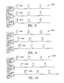
- FIG. 8 is a Q-switch modulation timing chart for the three laser head configuration of FIGS. 6 , 11 and 12 .
- FIG. 9 is another Q-switch modulation timing chart for the three laser head configuration of FIGS. 6 , 11 and 12 .
- FIG. 10 is another Q-switch modulation timing chart for the three laser head configuration of FIGS. 6 , 11 and 12 .
- FIG. 11 is a top view of the three laser head configuration of FIG. 6 .
- FIG. 12 is a perspective view of the three laser head configuration of FIG. 6 .
- FIGS. 13 and 13A are a schematic illustration of one exemplary method of laser beam combining and power scaling using first, second and third laser heads having first, second and third optical axes.
- FIGS. 14 and 14A are a schematic illustration of another exemplary method of a laser beam combining and power scaling using a plurality of parallel laser heads arranged with a series of beam splitters and a common output axis.
- Diode pumped solid state lasers have long lifetimes and enjoy high efficiencies. High electrical to optical efficiency leads to high overall power efficiency of the laser.
- Gain switched pulsed solid state lasers yield irregular pulses, namely, the pulses are irregular with respect to peak power, pulse width and repetition frequency.
- Q-switching greatly increases the peak power and the pulse widths have a short duration between several nanoseconds (10 ⁇ 9 ) and one microsecond (10 ⁇ 6 ) and can yield very high peak intensities.
- Q-switching is a method of laser generation where energy is stored in the laser medium and is suddenly released in a short pulse.
- the “Q” in “Q-switching” is the optical quality factor and is the ratio of the energy stored in the laser cavity to the energy lost per cycle.
- a Q switch may be thought of as a shutter between the active medium of the laser and the highly reflective mirror.
- Laser machining is material removal accomplished by laser material interaction including, but not limited to, laser drilling, laser cutting, laser grooving, marking or scribing. Machining or material removal with lasers involves absorption of laser radiation by the material, transmission and redistribution of the energy within the material to be machined or altered, and removal of the material by evaporation and/or melting (and removal by ejection of vacuum). Laser parameters which affect machining include wavelength, pulse width and energy, and beam intensity. Shortening of pulse length and increasing beam intensity facilitates machining with lasers.
- Shortening of pulse length and increase in beam intensity results in much thinner recast layers and heat affected zones (HAZ) and less micro-cracking or de-lamination of materials.
- FIG. 5 One example of the invention is set forth in FIG. 5 and schematically depicts a novel method of laser beam combining and power scaling using three highly reflective (HR) mirrors, one 50% beam splitter and at least two Q switches. This new method produces multiple direct feedback paths for each laser head which keeps the power in each head at lower individual levels while also allowing the laser heads to be fired (pulsed) simultaneously or independently.
- FIG. 6 Another example of the invention is set forth in FIG. 6 and schematically includes combining the laser beams from three laser heads (resonators).
- FIG. 7 Another example of the invention is set forth in FIG. 7 illustrating schematically five or more laser beams combined together into a single beam.
- the pulses can be emitted synchronously, multiplying the peak power by the number of heads in the configuration.
- the pulses can be emitted one after the other, increasing the pulse energy and duration without increasing the peak power.
- the pulses can be emitted with equal time between pulses, multiplying the repetition rate of the pulses. This cannot be done effectively using any of the current methods of laser power scaling.
- FIG. 5 is a schematic of one example of the invention illustrating laser beam combining and power scaling device 500 using two laser heads 501 , 502 , three highly reflective mirrors 503 , 504 , 505 , one 50% beam splitter 506 , a laser output 507 and vertical 501 A, 502 A and horizontal 501 B, 502 B Q-switches intermediate the two laser heads and their respective highly reflective mirrors. Q-switches create a large (energy magnitude expressed in Joules) pulse having a short pulse width. Both laser heads 501 , 502 are diode pumped (not shown).
- laser head 501 (typically an NdYAG laser head/medium) begins emission along the optical axes 508 , 509 when Q-switches 501 A, 501 B are energized by a high control signal as illustrated in FIG. 8 , 9 or 10 .
- Q-switches 501 A, 501 B are water cooled acousto-optical switches made by Gooch & Housego.
- Q-switch 501 A is a vertical Q-switch meaning that it deflects the radiation generated in the laser head vertically and
- Q-switch 501 B is a horizontal Q-switch meaning that it deflects the radiation horizontally. Deflection of the radiation prevents lasing.
- Laser head 502 (typically an NdYAG laser head/medium) begins emission along optical axes 512 , 513 when Q-switches 502 A, 502 B are energized by a high control signal as illustrated in FIG. 8 , 9 or 10 .
- Optical axis 511 is a third optical axis and it is coincident with optical axes 508 , 509 .
- First laser head 501 has a first optical axis 508 , 509 .
- the first laser head is diode pumped.
- a first highly reflective mirror 503 resides perpendicular to the first optical axis in alignment therewith behind the first laser head 501 and reflects radiation when emitted from the first laser head 501 .
- a first Q-switch 501 A in alignment with the first optical axis 508 , 509 is interposed between the first highly reflective mirror 503 and the first laser head 501 .
- the second laser head 502 has a second optical axis 512 , 513 .
- the second laser head 502 is also diode pumped.
- a second highly reflective mirror 504 resides perpendicular to the second optical axis in alignment therewith behind the second laser head 502 and reflects radiation when emitted from the second laser head 502 .
- a second Q-switch 502 A in alignment with the second optical axis is interposed between the second highly reflective mirror 504 and the second laser head 502 .
- a third optical axis 511 is coincident with said first optical axis 508 , 509 .
- a third highly reflective mirror 505 resides perpendicular to the third optical axis in alignment therewith.
- the second optical axis 512 , 513 perpendicularly intersects the first 508 , 509 and the third 511 optical axes.
- a beam splitter 506 resides at the intersection of the second optical axis and the first and third optical axes.
- Laser output 507 has a laser output axis coincident with the second optical axis 512 , 513 .
- the first laser head emits radiation along the first axis 509 into and through the beam splitter 506 .
- the beam splitter 506 directs a first portion of the radiation emitted from the first laser head along the third optical axis 511 and the beam splitter 506 directs a second portion of the radiation emitted from the first laser head along the laser output axis 507 coincident with the second optical axis 512 , 513 .
- the first portion of the radiation emitted from the first laser 501 head travels along the third axis 511 and is reflected by the third highly reflective mirror 505 toward the beam splitter.
- the beam splitter 506 directs a first portion of the radiation emitted from the third highly reflective mirror 505 into the first laser head along the first optical axis and the beam splitter directs a second portion of the radiation emitted from the third highly reflective mirror along the second optical axis into the second laser head.
- the second laser head emits radiation along the second axis into and through the beam splitter 506 .
- the beam splitter directs a first portion of the radiation emitted from the second laser head 502 along the laser output axis 507 and the beam splitter 506 directs a second portion of the radiation emitted from the second laser head 502 along the third optical axis and into the third highly reflective mirror 505 .
- a first control device 520 varies the timing, frequency and duration of the control signals to the first 501 A and second 502 A Q-switches.
- a second control device 521 pumps first 501 and second 502 laser heads 100% of the time when a diode pumped system is employed. Energy is applied to the laser heads 501 , 502 , 100% of the time. The energy may be in the form of light emitting diodes in the case of the diode pumping or it may be in the form of incoherent light in the case of lamp pumping.
- the laser output 507 emits radiation from the first and second laser heads along the laser output axis.
- the first 501 A and second 502 A Q-switches are vertical Q-switches meaning that they deflect the radiation upwardly (vertically) absent a control signal which defeats the deflection.
- the third Q-switch 501 B is interposed in alignment with the first optical axis 508 between the first Q-switch 501 A and the first laser head 501 .
- Third Q-switch 501 B is a horizontal Q-switch meaning that the radiation is deflected horizontally absent a control signal which defeats the deflection.
- a fourth Q-switch 502 B is interposed in alignment with the second optical axis between the second Q-switch 502 A and the second laser head 502 .
- Fourth Q-switch 502 B is a horizontal Q-switch meaning that the radiation is deflected horizontally absent a control signal which defeats the deflection.
- a first control device 520 varies the timing, frequency and duration of the actuation of the first and second Q-switches by modulating the first and second Q-switches simultaneously.
- the control device 520 provides a short duration, high power radiation pulse in the laser output axis upon the application of control signals to the first and second Q-switches as illustrated in FIG. 8 . It is not necessary to use both Q-switches 501 A, 501 B in the first optical axis 508 , nor is it necessary to use both Q-switches 502 A, 502 B in the second optical axis.
- Application of simultaneous pulses 801 , 802 to Q-switches 501 A, 502 A as set forth in FIG. 8 results in a high power radiation pulse which is the sum of the power produced by the first and second laser heads.
- FIGS. 8 , 9 and 10 are examples of control algorithms which may be used and the user may employ vastly different control algorithms depending on the use of the laser.
- the first control device 520 varies the timing, frequency and duration of the actuation of the first and second Q-switches by modulating the first and second Q-switches sequentially without any time between pulses.
- the control device 520 provides a short duration, high power radiation pulse in the laser output axis 507 .
- Application of sequential pulses 901 , 902 without any time between them 901 , 902 to Q-switches 501 A, 502 A as set forth in FIG. 9 results in a high power radiation pulse which is substantially equal to the individual power of the first and second laser heads with the pulse being twice as long as the first example stated above wherein the Q switches are modulated simultaneously.
- the first control device 520 varies the timing, frequency and duration of the actuation of the first and second Q-switches by modulating the first and second Q-switches sequentially but with time gaps therebetween.
- the control device 520 provides a series of short duration temporally spaced apart, high power radiation pulses in the laser output axis.
- Application of sequential pulses 1001 , 1002 spaced apart by time gaps therebetween to Q-switches 501 A, 502 A as set forth in FIG. 10 results in high power radiation pulses substantially equal to the individual power of the first and second laser heads spaced apart in time.
- FIG. 6 is a schematic 600 of another example of the invention illustrating a laser beam combining and power scaling using three laser heads 601 , 602 , 616 three highly reflective mirrors 603 , 604 , 618 , one 50% beam splitter 606 , a laser output 607 , and vertical 601 A, 602 A, 616 A and horizontal 601 B, 602 B, 616 B Q-switches intermediate the three laser heads and their respective highly reflective mirrors 603 , 604 , 618 .
- FIG. 6A is a schematic 600 A of another example of the invention illustrating a laser beam combining and power scaling using three laser heads, three highly reflective mirrors, one 50% beam splitter, and a laser output without the Q-switches.
- the examples set forth in FIGS. 6A and 7A may be used with different performance characteristics as the Q-switches provide short or narrow pulse widths and higher energy pulses as compared to un-switched laser heads.
- the q-switched beam combining system is used to narrow the optical pulse width at a given power level compared to a single laser at the same given power level.
- a current pulse may be applied to the laser heads.
- FIG. 6A reference numeral 622 is used to denote current pulse control of the laser heads.
- the current pulse control may be applied simultaneously to all the laser heads or it may be applied sequentially with no time gaps between the sequential firing of the lasers. Or, the lasers may be fired sequentially with time gaps therebetween.
- Different controls may be applied to the laser heads illustrated in FIG. 6A .
- the laser heads may be continuously energized and the output of FIG. 6A may be the sum of each of the three laser heads, 601 , 602 and 616 .
- Each of the laser heads may be operated, for instance, at fractional power enabling better control of the system. If a single laser head is used at full power, increased stress and heating on the optical components substantially lowers the quality of the laser beam creating lensing and optical waists that shift throughout the system and severely limits the power scaling achievable.
- First laser head 601 has a first optical axis 608 , 609 and is preferably diode pumped. Alternatively, laser head 601 may be lamp pumped.
- a first highly reflective mirror 603 resides perpendicular to the first optical axis 608 , 609 in alignment therewith behind the first laser head 601 reflecting radiation when emitted from the first laser head.
- a first Q-switch 601 A is interposed in alignment with the first optical axis 608 , 609 between the first highly reflective mirror 603 and the first laser head 601 .
- the second laser head 602 has a second optical axis 612 , 613 and the laser head is preferably diode pumped.
- a second highly reflective mirror 604 resides perpendicular to the second optical axis 612 , 613 in alignment therewith behind the second laser head reflecting radiation when emitted from the second laser head 602 .
- a second Q-switch 602 A is interposed in alignment with the second optical axis between the second highly reflective mirror and the first laser head.
- the third laser head 616 has a third optical axis 615 , 617 , and the third laser head is diode pumped.
- a third highly reflective mirror 618 resides perpendicular to the third optical axis in alignment therewith behind the third laser head 616 .
- a third Q-switch 616 A in alignment with the third optical axis 615 , 617 is interposed between the third highly reflective mirror and the third laser head.
- the first and third optical axes are coincident.
- the second optical axis 612 , 613 perpendicularly intersects the first and third optical axes 608 , 609 ; 615 , 617 .
- a beam splitter 606 resides at the intersection of the second optical axis 612 , 613 and the first and third optical axes.
- a laser output 607 has a laser output axis coincident with the second optical axis.
- the first laser head 601 emits radiation along the first optical axis 609 into and through the beam splitter 606 , the beam splitter directs a first portion of the radiation emitted from the first laser head 601 into the third laser head 616 along the third optical axis 615 .
- the beam splitter directs a second portion of the radiation emitted from the first laser head along the laser output axis 607 coincident with the second optical axis 613 .
- the third laser head emits radiation along the third axis 615 into and through the beam splitter 606 .
- the beam splitter directs a first portion of the radiation emitted from the third laser head 616 into the first laser head 601 along the first optical axis 609 where some of the radiation passes therethrough and is reflected from highly reflective mirror 618 .
- the beam splitter directs a second portion of the radiation emitted from the third laser head 616 along the second optical axis 613 into the second laser head 602 where some of the radiation passes therethrough and is reflected from highly reflective mirror 603 .
- the second laser head 602 emits radiation along the second axis into and through the beam splitter 606 .
- the beam splitter directs a first portion of the radiation emitted from the second laser head along the laser output axis 607 .
- the beam splitter directs a second portion of the radiation emitted from the second laser head 602 along the third optical axis 615 and into the third laser head 618 where some of the radiation passes therethrough and is reflected from highly reflective mirror 618 .
- a first control device 620 varies the timing, frequency and duration of control signals to the first 601 A, second 602 A and third 616 A Q-switches.
- a second control device 621 pumps the first 601 , second 602 and third 616 laser heads continuously, 100% of the time.
- the laser output 607 emits radiation from the first, second and third laser heads along the laser output axis.
- one operational example (the first example pertaining to FIG. 6 ) of the first control device 620 is given wherein the timing, frequency and duration of the actuation of the first, second and third Q-switches is varied by modulating the first, second and third Q-switches simultaneously.
- the first control device provides a short duration, high power radiation pulse in the laser output axis 607 , and, the high power radiation pulse is the sum of the energy and power produced by the first 601 , second 602 and third 616 laser heads.
- FIG. 8 a Q-switch modulation timing chart for the three laser head configuration of FIGS. 6 , 11 and 12 is disclosed wherein all three laser heads are fired simultaneously. As stated above, FIG.
- FIG. 8 is applicable to the operation of a two headed laser system and illustrates the simultaneous occurrence of control impulses to the Q-switches to permit lasing.
- FIG. 6 illustrates two sets of Q-switches in the first 608 , second 612 and third 617 optical axes.
- Q-switches 601 A, 602 A and 616 A are vertical Q-switches meaning that the radiation beam is deflected vertically. These vertical acousto-optical Q-switches alone are sufficient to hold off lasing although it is preferred to include horizontal Q-switches 601 B, 602 B and 616 B in each of the optical axes as well to reduce the power supplied to each Q-switch.
- FIG. 6 another operational example (the second example pertaining to FIG. 6 ) of the first control device is given wherein the timing, frequency and duration of the actuation of the first and second Q-switches is varied by modulating the first, second and third Q-switches sequentially without any time between pulses.
- the control signals 901 , 902 , and 903 defeat the Q-switches halting deflection of the radiation and providing a short duration, high power optical radiation pulse in the laser output axis.
- the short duration high power optical radiation pulse is substantially equal to the individual energy and power of the first, second and third laser heads.
- the short duration high power pulse of the example of FIG. 9 will be substantially three times as long as the first operational example.
- FIG. 6 another operational example (the third example pertaining to FIG. 6 ) of the first control device is given wherein the timing, frequency and duration of the actuation of the first, second, and third Q-switches is varied by modulating the first, second, and third Q-switches sequentially but with time gaps therebetween.
- the first control device provides a series of short duration temporally spaced apart, high power radiation pulses in the laser output axis.
- the high power optical radiation pulses are substantially equal in magnitude to the individual power of the first, second, and third laser heads.
- the control algorithm applied to a single Q-switch in each optical axis, for instance Q-switches 601 A, 602 A and 616 A if they were used alone, is given in FIG.
- Q-switched performance of the example illustrated in FIG. 6 at 10 kHz, provides average power of 660 W (Watts), pulse energy of 66 mJ (milli Joules), nominal pulse width of 75 ns (nanoseconds) and peak pulse power of approximately 880 kW (kilo watts).
- Operation at 15 kHz yields average power of 700 W (Watts), pulse energy of 47 mJ (milli Joules), nominal pulse width of 100 ns (nanoseconds) and peak pulse power of approximately 470 kW (kilo watts).
- Operation at 20 kHz yields average power of 700 W (Watts), pulse energy of 35 mJ (milli Joules), nominal pulse width of 110 ns (nanoseconds) and peak pulse power of approximately 318 kW (kilo watts).
- FIG. 6 by way of example employs diode pumped NdYAG laser heads. Thirty six (36) diodes rated at 40 W are used and are pumped at a wavelength of 808 nm. Radio frequency power up to 100 W is applied to water cooled acousto optical Q switches. Q switch actuation (RF off time) is typically 8 ⁇ s.
- FIG. 6B illustrates graphically the total power delivered (laser output) simultaneously from the three head laser of FIG. 6 plotted against the current supplied to the diodes. Testing performed on the three headed laser at 1064 nm was performed having a spot size of 4 mm with a divergence of 11.4 mr (milli-radians).
- FIG. 7 is a schematic 700 of another example of the invention illustrating laser beam combining and power scaling using five laser heads 701 , 702 , 703 , 704 , 705 , eleven highly reflective mirrors 701 C, 702 C, 703 C, 704 C, 705 C, 701 B, 702 B, 703 B, 704 B, 705 B, 777 , five 701 S, 702 S, 703 S, 704 S, 705 S, 50% beam splitters, a laser output 711 , and vertical 701 A, 702 A, 703 A, 704 A, 705 A and horizontal 701 D, 702 D, 703 D, 704 D, 705 D Q-switches intermediate the five laser heads and their respective highly reflective mirrors 701 B, 702 B, 703 B, 704 B, 705 B.
- FIG. 7A is a schematic 700 A of another example of the invention illustrating laser beam combining and power scaling using five laser heads, eleven highly reflective mirrors, five 50% beam splitters, a laser output.
- the example of FIG. 7A may be used with laser heads that are pumped with current pulses as described in connection with FIG. 6A above.
- a laser beam combining and power scaling device 700 is illustrated in FIG. 7 and comprises a plurality of laser heads arranged in parallel.
- the plurality of laser heads 701 , 702 , 703 , 704 , 705 emit radiation.
- the lasers are preferably diode pumped and the preferred laser medium is NdYAG.
- a plurality of respective optical axes ( 712 , 717 -first optical axis; 713 , 718 -second optical axis; 714 , 719 -third optical axis; 715 , 720 -fourth optical axis and 716 , 721 -fifth optical axis) are aligned with respective ones of the plurality of laser heads.
- a plurality of first highly reflective mirrors 701 B, 702 B, 703 B, 704 B, 705 B resides perpendicularly with respective ones of the plurality of optical axes 712 , 713 , 714 , 715 and behind respective ones of the plurality of the laser heads.
- a plurality of second highly reflective mirrors 701 C, 702 C, 703 C, 704 C, 705 C reside perpendicularly with respective ones of the plurality of optical axes 727 , 728 , 729 , 730 , 731 which are coincident with the optical axis of the laser heads.
- a plurality of beam splitters 701 S, 702 S, 703 S, 704 S, 705 S are arranged at an incidence angle (typically 45°) with respect to respective ones of the optical axes 717 , 718 , 719 , 720 , 721 and reside intermediate the respective ones of the plurality of laser heads and the plurality of second highly reflective mirrors 701 C, 702 C, 703 C, 704 C, 705 C.
- a common laser output axis 711 comprises output optical axes 706 , 707 , 708 , 709 , 710 , the output optical axes 707 , 708 , 709 and 710 residing intermediate the beam splitters as illustrated in FIGS.
- the plurality of beam splitters direct respective first portions of radiation emitted from the plurality of laser heads along the common laser output axis 706 , 707 , 708 , 709 , 710 , 711 .
- the plurality of beam splitters 701 S, 702 S, 703 S, 704 S, 705 S direct respective second portions of the radiation emitted from the plurality of laser heads through the beam splitter along the respective ones 727 , 728 , 729 , 730 , 731 of the optical axes toward the plurality of second highly reflective mirrors 701 C, 702 C, 703 C, 704 C, 705 C.
- a common output axis highly reflective mirror 777 resides perpendicularly along the common laser output axis 706 , 707 , 708 , 709 , 710 , 711 .
- the plurality of second highly reflective mirrors 701 C, 702 C, 703 C, 704 C, 705 C reside perpendicularly with respect to respective ones of the plurality of optical axes 727 , 728 , 729 , 730 , 731 reflecting the respective plurality of second portions of the radiation emitted from the plurality of laser heads 701 , 702 , 703 , 704 , 705 along the respective ones of the optical axes 727 , 728 , 729 , 730 , 731 toward the respective ones of the beam splitters.
- the plurality of beam splitters direct respective first portions of radiation emitted from the respective ones of the plurality of second highly reflective mirrors 701 C, 702 C, 703 C, 704 C, 705 C along the common output axis 706 , 707 , 708 , 709 , 710 , 711 toward the common output axis highly reflective mirror 777 residing perpendicularly to the common output axis.
- the plurality of beam splitters direct respective second portions of radiation emitted from the respective ones of the plurality of second highly reflective mirrors through the beam splitter toward the respective ones of the plurality of laser heads 701 , 702 , 703 , 704 , 705 .
- the common output axis mirror 777 reflects the respective first portions of radiation received from the plurality of second highly reflective mirrors toward the plurality of beam splitters 701 S, 702 S, 703 S, 704 S, 705 S.
- the plurality of beam splitters direct a plurality of first portions of radiation from the common output axis highly reflective mirror 777 through the beam splitters and along the common laser output axis 706 , 707 , 708 , 709 , 710 , 711 .
- the beam splitters also direct the first portions of radiation emitted from the plurality of laser heads along the common laser output axis.
- Common output axis 706 , 707 , 708 , 709 , 710 , and 711 carries coherent light (radiation) which is emitted as indicated in FIG. 7 .
- the plurality of beam splitters direct a plurality of second portions of radiation from the common output axis highly reflective mirror 777 toward the second highly reflective mirrors 701 C, 702 C, 703 C, 704 C, 705 C along said respective ones of said optical axes 727 , 728 , 729 , 730 , 731 .
- a plurality of first acousto-optical Q-switches 701 A, 702 A, 703 A, 704 A, 705 A reside in respective ones of the plurality of the optical axes 712 , 713 , 714 , 715 , 716 between the respective ones of the laser heads 701 , 702 , 703 , 704 , 705 and the plurality of the first highly reflective mirrors 701 B, 702 B, 703 B, 704 B, 705 B.
- the first Q-switches are vertical Q-switches.
- a plurality of second acousto-optical Q-switches 702 D, 703 D, 704 D, 705 D reside in respective ones of the plurality of the optical axes between the plurality of first Q-switches and the respective ones of the laser heads.
- the plurality of second Q-switches are horizontal Q-switches.
- a first control device 740 varies the timing, frequency and duration of control signals to the first and second Q-switches.
- a second control device 741 applies constant direct current pumping of the laser heads.
- one exemplary mode (first example) of the first control device varies the timing, frequency and duration of the actuation of the first and second Q-switches and modulates the Q-switches simultaneously for all of the laser heads. See, FIG. 8 as described above in connection with the combination of 2 and 3 laser heads.
- a plurality of control signals are necessary, one for each laser head.
- Simultaneous application of control signals to the Q-switch of all laser heads provides a short duration, high power radiation pulse in the laser output axis.
- the high power radiation pulse is the sum of the energy power produced by all of the laser heads.
- another exemplary mode (second example) of the first control device 740 varies the timing, frequency and duration of the actuation of the switches by modulating the Q-switches sequentially without any time between pulses.
- each of the laser heads fire in sequence beginning with 701 , 702 , 703 etc.
- This control algorithm as expressed in FIG. 9 provides a short duration, high power radiation pulse in the laser output axis.
- the magnitude of the high energy high power radiation pulse is substantially equal to the individual energy and power of the individual laser heads. In other words, this example provides a lower magnitude pulse than the first example but the pulse would be longer by the number of laser heads.
- another exemplary mode (third example) of the first control device varies the timing, frequency and duration of the actuation of the Q-switches by modulating the Q-switches sequentially but with time gaps therebetween.
- This example provides a series of short duration temporally spaced apart, high power radiation pulses in the laser output axis. The magnitude of the high power radiation pulses are substantially equal in energy and power to the individual energy and power of the individual laser heads.
- reference numeral 742 denotes application and control of a current pulse to the parallel laser heads 701 , 702 , 703 , 704 and 705 .
- the current pulse control 742 may be applied simultaneously to all the parallel laser heads.
- current pulse control may be sequenced such that each of the laser heads are fired sequentially.
- current pulse control may be sequenced such that the current pulses are spaced apart in time.
- FIG. 8 is a Q-switch modulation timing chart of the control device 620 for the three laser head configuration of FIGS. 6 , 11 and 12 .
- Impulse 801 to Q-switch occurs simultaneously with impulses 802 and 803 which then removes the deflection of laser beam. If two Q-switches are used per laser head then the control impulses actuate both the vertical and horizontal Q-switches simultaneously.
- FIG. 9 is another Q-switch modulation timing chart of the control device 620 for the three laser head configuration FIGS. 6 , 11 and 12 .
- Reference numeral 901 is a sequential impulse to Q-switch removing deflection of the laser beam of the first laser head followed by sequential impulse 902 to another Q-switch for removing deflection of the laser beam in the second laser head following impulse 901 .
- reference numeral 903 is a sequential impulse to Q-switch removing deflection of the laser beam for the third laser head.
- FIG. 10 is another Q-switch modulation timing chart for the three laser head configuration of FIGS. 6 , 11 and 12 .
- Reference numeral 1001 is a sequential impulse to the first Q-switch removing deflection of the laser beam followed by the spaced apart sequential impulse 1002 to the Q-switch removing deflection of laser beam for the second laser head followed by sequential impulse 1003 to the Q-switch removing deflection of laser beam for the third laser head.
- Each of the sequenced impulses is spaced apart in time.
- FIG. 11 is a top view 1100 of the three laser head configuration of FIG. 6 .
- the laser heads, the Q-switches and the beam splitter as discussed above are all illustrated in FIG. 11 .
- FIG. 11 conserves space through the use of folding mirrors 1187 , 1189 .
- Apertures 1102 , 1103 , 1104 , 1105 , 1106 , 1107 are used as mode control devices producing higher quality beams.
- the mounting frame is denoted by reference numeral 1101 and the side of the frame is denoted by reference numeral 1111 .
- FIG. 12 is a perspective view 1200 of the three laser head configuration of FIG. 6 . 1200 -perspective view corresponding to the schematic view of FIG. 6
- One exemplary method as set forth in FIG. 13 utilizes: a first highly reflective mirror residing perpendicular to the first optical axis in alignment therewith behind the first laser head reflecting radiation when emitted from the first laser head, a first Q-switch in alignment with the first optical axis interposed between the first highly reflective mirror and the first laser head, a second highly reflective mirror residing perpendicular to the second optical axis in alignment therewith behind the second laser head reflecting radiation when emitted from the second laser head; a second Q-switch in alignment with the second optical axis interposed between the second highly reflective mirror and the second laser head, a third highly reflective mirror residing perpendicular to the third optical axis in alignment therewith behind the third laser head, a third Q-switch in alignment with the third optical axis interposed between the third highly reflective mirror and the third laser head, the first and third optical axes being coincident, the second optical axis perpendicularly intersecting the first and the third optical axes, a
- the method as illustrated 1300 in FIG. 13 comprises the steps of: emitting radiation from the first laser head along the first axis into and through the beam splitter— 1301 ; directing, using the beam splitter, a first portion of the radiation emitted from the first laser head into the third laser head along the third optical axis— 1302 ; directing, using the beam splitter, a second portion of the radiation emitted from the first laser head along the laser output axis coincident with the second optical axis— 1303 ; emitting radiation from the third laser head along the third axis into and through the beam splitter— 1304 ; directing, using the beam splitter, a first portion of the radiation emitted from the third laser head into the first laser head along the first optical axis— 1305 ; directing, using the beam splitter, a second portion of the radiation emitted from the third laser head along the second optical axis into the second laser head emitting radiation from the second laser head along the second axis into and through the beam splitter— 13
- the method may include controlling, using the first control device, and varying the timing, frequency and duration of the actuation of the first, second and third Q-switches, includes modulating the first, second and third Q-switches simultaneously— 1312 .
- This provides a short duration, high power radiation pulse in the laser output axis.
- the high power radiation pulse is the sum of the power produced by the first, second and third laser heads— 1313 .
- the method may include controlling, using the first control device, and varying the timing, frequency and duration of the actuation of the first, second and third Q-switches by modulating the first, second and third Q-switches sequentially without any time between pulses— 1314 .
- This provides a short duration, high power radiation pulse in the laser output axis, the high power radiation pulse is substantially equal to the individual power of the first, second and third laser heads— 1315 .
- the method may include controlling, using the first control device, and varying the timing, frequency and duration of the actuation of the first, second and third Q-switches by modulating the first, second and third Q-switches sequentially, but with time gaps therebetween— 1316 .
- This provides a series of short duration temporally spaced apart, high power radiation pulses in the laser output axis.
- Each of the high power radiation pulses is substantially equal to the individual power of the first, second and third laser heads— 1317 .
- Another exemplary laser beam combining and power scaling method as illustrated in FIG. 14 uses a plurality of laser heads arranged in parallel, the plurality of laser heads emitting radiation, a plurality of respective optical axes aligned with respective ones of the plurality of laser heads, a plurality of first highly reflective mirrors residing perpendicularly with respect to respective ones of the plurality of the optical axes and behind respective ones of the plurality of the laser heads, a plurality of second highly reflective mirrors residing perpendicularly with respect to respective ones of the plurality of optical axes, a plurality of beam splitters arranged at an incidence angle with respect to respective ones of the optical axes aligned with respective ones of the plurality of laser heads, the plurality of beam splitters reside intermediate the respective ones of the plurality of laser heads and the plurality of second highly reflective mirrors, a common laser output axis, and a common output axis highly reflective mirror residing perpendicularly with respect to and along the common laser output axis.
- the method as set forth in FIG. 14 comprises the steps of: directing, using the plurality of beam splitters, respective first portions of radiation emitted from the plurality of laser heads along the common laser output axis 1401 ; directing, using the plurality of beam splitters, respective second portions of the radiation emitted from the plurality of laser heads along the respective ones of the optical axes through the respective beam splitter and toward the plurality of second highly reflective mirrors— 1402 ; reflecting, using the plurality of second highly reflective mirrors residing perpendicularly with respect to respective ones of the plurality of optical axes, the respective plurality of second portions of the radiation emitted from the plurality of laser heads along the respective ones of the optical axes toward the respective ones of the beam splitters— 1403 ; directing, using the plurality of beam splitters, respective first portions of radiation emitted from the respective ones of the plurality of second highly reflective mirrors along the common output axis toward the common output axis highly reflective mirror residing perpendicularly with respect to the common
- An exemplary control algorithm may be applied for the plurality of laser heads arranged in parallel.
- the step of controlling, using the first control device, the timing, frequency and duration of the actuation of the Q-switches includes modulation of the Q-switches simultaneously— 1412 , thus providing a short duration, high power radiation pulse in the laser output axis.
- the high power radiation pulse is the sum of the power produced by the plurality of laser heads arranged in parallel— 1413 .
- another exemplary control algorithm using the first control device, to vary the timing, frequency and duration of the actuation of the Q-switches, includes modulation of the Q-switches sequentially without any time between pulses— 1414 , thus providing a short duration, high power radiation pulse in the laser output axis.
- the high power radiation pulse is substantially equal to the individual power of the ones of the plurality of the laser heads— 1415 .
- another exemplary control algorithm using the first control device to vary the timing, frequency and duration of the actuation of the Q-switches, includes modulation of the Q-switches sequentially but with time gaps therebetween— 1416 , thus providing a series of short duration temporally spaced apart, high power radiation pulse in the laser output axis.
- the high power radiation pulse is substantially equal to the individual power of the ones of the plurality of the laser heads— 1417 .
Abstract
Description
- 10—prior art laser beam combination system
- 20—first laser source
- 22—second laser source
- 30—fully reflective mirror
- 32—fully reflective mirror
- 36—fully reflective mirror
- 40—beam splitter
- 50—laser output
- 51—line
- 52—optical axis, line
- 54—optical axis, line
- 55—optical axis, line
- 56—optical axis, line
- 100—prior art standard laser system
- 101—laser head/medium
- 102—partially reflective output coupler
- 103—highly reflective mirror
- 104—optical axis/line
- 105—optical axis/line
- 106—laser output
- 200—multiple intra-cavity oscillator
- 201—second laser head/medium
- 202—optical axis/line, combined output of first and second laser head/medium
- 203—partially reflective output coupler
- 204—laser output
- 300—master oscillator power amplifier (MOPA)
- 301—second laser source
- 302—partially reflective output coupler intermediate first laser source and second laser source
- 303—optical axis/line
- 304—laser output
- 400—prior art laser beam combination system
- 500—continuous wave Q switched laser beam combination system
- 501—first laser source
- 501A—vertical acousto-optic Q switch
- 501B—horizontal electro-optic Q switch
- 502—second laser source
- 502A—vertical acousto-optic Q switch
- 502B—horizontal electro-optic Q switch
- 503—highly reflective mirror
- 504—highly reflective mirror
- 505—highly reflective mirror
- 506—beamsplitter, 50%
- 507—laser output
- 508—optical axis/line
- 509—optical axis/line
- 511—optical axis/line
- 512—optical axis/line
- 513—optical axis/line
- 520—first control device
- 521—second control device
- 600—continuous wave Q-switched laser beam combination system using three laser sources
- 600A—current pulsed laser beam combination system without Q-switching
- 601—first laser source
- 601A—vertical acousto-optic Q switch
- 601B—horizontal electro-optic Q switch
- 602—second laser source
- 602A—vertical acousto-optic Q switch
- 602B—horizontal acousto-optic Q switch
- 603—highly reflective mirror
- 604—highly reflective mirror
- 606—beamsplitter, 50%
- 607—laser output
- 608—optical axis/line
- 609—optical axis/line
- 612—optical axis/line
- 613—optical axis/line
- 615—optical axis/line
- 616—third laser source
- 616A—vertical acousto-optic Q switch
- 616B—horizontal acousto-optic Q switch
- 617—optical axis/line
- 618—highly reflective mirror
- 620—first control device
- 621—second control device for constant direct current application to the laser heads
- 622—current pulsing of the laser heads
- 700—continuous wave Q-switched laser beam combination system employing 4 or more laser sources
- 700A—current pulsed laser beam combination system employing 4 or more laser sources without Q-switching
- 701—laser source
- 701A, 702A, 703A, 704A, 705A—vertical acousto-optic Q switch
- 701B—highly reflective mirror
- 701C—highly reflective mirror
- 701D, 702S, 703D, 704D, 705D—horizontal acousto-optic Q switch
- 701S, 702S, 703S, 704S, 705S—beamsplitter, 50%
- 702—laser source
- 702B—highly reflective mirror
- 702C—highly reflective mirror
- 703—laser source
- 703B—highly reflective mirror
- 703C—highly reflective mirror
- 704—laser source
- 704B—highly reflective mirror
- 704C—highly reflective mirror
- 705—laser source
- 705B—highly reflective mirror
- 705C—highly reflective mirror
- 706, 707, 708, 709, 710—output optical axis/line
- 711—laser output
- 712, 717—first optical axis/line
- 713, 718—second optical axis/line
- 714, 719—third optical axis/line
- 715, 720—fourth optical axis/line
- 716, 721—fifth optical axis/line
- 727—optical axis/line
- 728—optical axis/line
- 729—optical axis/line
- 730—optical axis/line
- 731—optical axis/line
- 740—first control device
- 741—second control device for constant direct current application to the laser heads
- 742—current pulse control of the laser heads
- 777—highly reflective mirror
- 800—Q-switch modulation timing diagram for example disclosed in
FIGS. 6 , 11 and 12 - 801—impulse to Q-switch occurring simultaneously with
impulse - 802—impulse to Q-switch occurring simultaneously with
impulse - 803—impulse to Q-switch occurring simultaneously with
impulse - 900—Q-switch modulation timing diagram for example disclosed in
FIGS. 6 , 11 and 12 - 901—sequential impulse to Q-switch removing deflection of laser beam
- 902—sequential impulse to Q-switch removing deflection of laser beam after
impulse 901 - 903—sequential impulse to Q-switch removing deflection of laser beam after
impulse 902 - 1000—Q-switch modulation timing diagram for example disclosed in
FIGS. 6 , 11 and 12 - 1001—sequential impulse to Q-switch removing deflection of laser beam
- 1002—sequential impulse to Q-switch removing deflection of laser beam after
impulse 1001 - 1003—sequential impulse to Q-switch removing deflection of laser beam after
impulse 1002 - 1100—top view corresponding to the schematic view of
FIG. 6 - 1101—mounting frame
- 1102—aperture, mode control device producing higher quality beams, blocks stray rays
- 1103—aperture, mode control device producing higher quality beams, blocks stray rays
- 1104—aperture, mode control device producing higher quality beams, blocks stray rays
- 1105—aperture, mode control device producing higher quality beams, blocks stray rays
- 1106—aperture, mode control device producing higher quality beams, blocks stray rays
- 1107—aperture, mode control device producing higher quality beams, blocks stray rays
- 1111—side of mounting frame
- 1187—steering/folding mirror
- 1189—steering/folding mirror
- 1200—perspective view corresponding to the schematic view of
FIG. 6 - 1300—laser beam combining and power scaling method using first, second and third laser heads having first, second and third optical axes
- 1301—emitting radiation from the first laser head along the first axis into and through the beam splitter
- 1302—directing, using the beam splitter, a first portion of the radiation emitted from the first laser head into the third laser head along the third optical axis
- 1303—directing, using the beam splitter, a second portion of the radiation emitted from the first laser head along the laser output axis coincident with the second optical axis
- 1304—emitting radiation for the third laser head along the third axis into and through the beam splitter
- 1305—directing, using the beam splitter, a first portion of the radiation emitted from the third laser head into the first laser head along the first optical axis
- 1306—directing, using the beam splitter, a second portion of the radiation emitted from the third laser head along the second optical axis into the second laser head emitting radiation from the second laser head along the second axis into and through the beam splitter
- 1307—directing, using the beam splitter, a first portion of the radiation emitted from the second laser head along the laser output axis
- 1308—directing, using the beam splitter, a second portion of the radiation emitted from the second laser head along the third optical axis and into the third laser head
- 1309—controlling, using a first control device, the timing, frequency and duration of the actuation of the first, second and third Q-switches
- 1311—outputting, radiation from the first, second and third laser heads along the laser output axis
- 1312—controlling, using a first control device, the timing, frequency and duration of the actuation of the first and second Q-switches includes modulation of the first, second and third Q-switches simultaneously
- 1313—providing a short duration, high power radiation pulse in the laser output axis, the high power radiation pulse is the sum of the power produced by the first, second and third laser heads.
- 1314—controlling, using a first control device, the timing, frequency and duration of the actuation of the first, second and third Q-switches includes modulation of the first and second Q-switches sequentially without any time between pulses
- 1315—providing a short duration, high power radiation pulse in the laser output axis, the high power radiation pulse is substantially equal to the individual power of the first and second laser heads
- 1316—controlling, using a first control device, the timing, frequency and duration of the actuation of the first and second Q-switches includes modulation of the first, second and third Q-switches sequentially but with time gaps therebetween
- 1317—providing a series of short duration temporally spaced apart, high power radiation pulse in the laser output axis, the high power radiation pulse is substantially equal to the individual power of the first, second and third laser heads.
- 1400—a laser beam combining and power scaling method using a plurality of laser heads arranged in parallel,
- 1401—directing, using the plurality of beam splitters, respective first portions of radiation emitted from the plurality of laser heads along the common laser output axis
- 1402—directing, using the plurality of beam splitters, respective second portions of the radiation emitted from the plurality of laser heads along the respective ones of the optical axes toward the plurality of second highly reflective mirrors
- 1403—reflecting, using the plurality of second highly reflective mirrors residing perpendicularly with respective ones of the plurality of optical axes, the respective plurality of second portions of the radiation emitted from the plurality of laser heads along the respective ones of the optical axes toward the respective ones of the beam splitters
- 1404—directing, using the plurality of beam splitters, respective first portions of radiation emitted from the respective ones of the plurality of second highly reflective mirrors along the common output axis toward the common output axis highly reflective mirror residing perpendicularly to the common output axis
- 1405—directing, using the plurality of beam splitters, respective second portions of radiation emitted from the respective ones of the plurality of second highly reflective mirrors toward the respective ones of the plurality of laser heads
- 1406—reflecting, using the common output axis mirror, the respective first portions of radiation received from the plurality of second highly reflective mirrors toward the plurality of beam splitters
- 1407—directing, using the plurality of the beam splitters, a plurality of first portions of radiation from the common output axis highly reflective mirror through the beam splitters along the common laser output axis
- 1408—directing, using the plurality of the beam splitters, a plurality of second portions of radiation from the common output axis highly reflective mirror toward the second highly reflective mirrors
- 1409—controlling, using a first control device, the timing, frequency and duration of the actuation of the Q-switches
- 1411-outputting, radiation from the laser heads along the laser output axis
- 1412—controlling, using the first control device, the timing, frequency and duration of the actuation of the Q-switches via modulation of the Q-switches simultaneously
- 1413—providing a short duration, high power radiation pulse in the laser output axis, the high power radiation pulse is the sum of the power produced by the plurality of laser heads arranged in parallel
- 1414—controlling, using the first control device, the timing, frequency and duration of the actuation of the Q-switches via modulation of the Q-switches sequentially without any time between pulses
- 1415—providing a short duration, high power radiation pulse in the laser output axis, the high power radiation pulse is substantially equal to the individual power of the ones of the plurality of the laser heads
- 1416—controlling, using the first control device, the timing, frequency and duration of the actuation of the first and second Q-switches via modulation of the Q-switches sequentially but with time gaps therebetween
- 1417—providing a series of short duration temporally spaced apart, high power radiation pulse in the laser output axis, the high power radiation pulse is substantially equal to the individual power of the ones of the plurality of the laser heads.
Claims (17)
Priority Applications (4)
| Application Number | Priority Date | Filing Date | Title |
|---|---|---|---|
| US12/481,784 US8509272B2 (en) | 2009-06-10 | 2009-06-10 | Laser beam combining and power scaling device |
| US13/932,180 US8693511B2 (en) | 2009-06-10 | 2013-07-01 | Laser device and method |
| US14/187,308 US9106054B2 (en) | 2009-06-10 | 2014-02-23 | Laser device and method |
| US14/822,818 US9647417B2 (en) | 2009-06-10 | 2015-08-10 | Laser device and method |
Applications Claiming Priority (1)
| Application Number | Priority Date | Filing Date | Title |
|---|---|---|---|
| US12/481,784 US8509272B2 (en) | 2009-06-10 | 2009-06-10 | Laser beam combining and power scaling device |
Related Child Applications (1)
| Application Number | Title | Priority Date | Filing Date |
|---|---|---|---|
| US13/932,180 Division US8693511B2 (en) | 2009-06-10 | 2013-07-01 | Laser device and method |
Publications (2)
| Publication Number | Publication Date |
|---|---|
| US20100316071A1 US20100316071A1 (en) | 2010-12-16 |
| US8509272B2 true US8509272B2 (en) | 2013-08-13 |
Family
ID=43306408
Family Applications (4)
| Application Number | Title | Priority Date | Filing Date |
|---|---|---|---|
| US12/481,784 Expired - Fee Related US8509272B2 (en) | 2009-06-10 | 2009-06-10 | Laser beam combining and power scaling device |
| US13/932,180 Active US8693511B2 (en) | 2009-06-10 | 2013-07-01 | Laser device and method |
| US14/187,308 Expired - Fee Related US9106054B2 (en) | 2009-06-10 | 2014-02-23 | Laser device and method |
| US14/822,818 Active US9647417B2 (en) | 2009-06-10 | 2015-08-10 | Laser device and method |
Family Applications After (3)
| Application Number | Title | Priority Date | Filing Date |
|---|---|---|---|
| US13/932,180 Active US8693511B2 (en) | 2009-06-10 | 2013-07-01 | Laser device and method |
| US14/187,308 Expired - Fee Related US9106054B2 (en) | 2009-06-10 | 2014-02-23 | Laser device and method |
| US14/822,818 Active US9647417B2 (en) | 2009-06-10 | 2015-08-10 | Laser device and method |
Country Status (1)
| Country | Link |
|---|---|
| US (4) | US8509272B2 (en) |
Families Citing this family (10)
| Publication number | Priority date | Publication date | Assignee | Title |
|---|---|---|---|---|
| JP5556431B2 (en) * | 2010-06-24 | 2014-07-23 | 富士電機株式会社 | Manufacturing method of semiconductor device |
| CN103326230B (en) * | 2013-06-25 | 2015-08-26 | 江苏中科四象激光科技有限公司 | A kind of also association bundle method realizing all solid state laser high-power output |
| US10195692B2 (en) * | 2014-06-12 | 2019-02-05 | General Electric Company | Parallel direct metal laser melting |
| CN104037615A (en) * | 2014-06-13 | 2014-09-10 | 鞍山华科大激光科技有限公司 | High power pulse solid laser capable of being clipped |
| US9525265B2 (en) | 2014-06-20 | 2016-12-20 | Kla-Tencor Corporation | Laser repetition rate multiplier and flat-top beam profile generators using mirrors and/or prisms |
| DE102014013567B3 (en) * | 2014-09-18 | 2015-10-08 | Iai Industrial Systems B.V. | Q-switched CO2 laser material processing system with acousto-optic modulators |
| CN104385795B (en) * | 2014-10-24 | 2017-11-03 | 常熟阿特斯阳光电力科技有限公司 | The modification method and system of a kind of photovoltaic module bar code information |
| CN105006738A (en) * | 2015-08-12 | 2015-10-28 | 广州安特激光技术有限公司 | Parallel connection end-pumped series amplifying high-power laser |
| CN108346971A (en) * | 2018-04-08 | 2018-07-31 | 北京华宇德信光电技术有限公司 | A kind of acousto-optic Q modulation frequency double laser using electrooptical switching control laser output |
| CN112432664B (en) * | 2020-11-11 | 2022-04-08 | 山东大学 | All-fiber laser detection system for tunnel safety monitoring and working method |
Citations (32)
| Publication number | Priority date | Publication date | Assignee | Title |
|---|---|---|---|---|
| US3510798A (en) | 1967-05-16 | 1970-05-05 | Trw Inc | Holocamera illuminator |
| US3855544A (en) | 1966-10-28 | 1974-12-17 | Raytheon Co | Frequency selective output coupling for lasers |
| US4145714A (en) | 1978-02-27 | 1979-03-20 | Robert W. MacDonald | Television flaw detector for inspecting the wall surface of a hole through a circuit board |
| US4560273A (en) | 1982-11-30 | 1985-12-24 | Fujitsu Limited | Method and apparatus for inspecting plated through holes in printed circuit boards |
| US4596037A (en) | 1984-03-09 | 1986-06-17 | International Business Machines Corporation | Video measuring system for defining location orthogonally |
| US4667231A (en) | 1979-09-07 | 1987-05-19 | Diffracto Ltd. | Electro-optical part inspection in the presence of contamination and surface finish variation |
| US4707073A (en) | 1985-09-04 | 1987-11-17 | Raytheon Company | Fiber optic beam delivery system for high-power laser |
| US4712916A (en) | 1985-01-28 | 1987-12-15 | International Business Machines Corporation | Apparatus for inspection of the walls of deep holes of minute diameter |
| JPS63136897A (en) | 1986-11-28 | 1988-06-09 | Noritsu Co Ltd | Remote control equipment |
| US4805181A (en) | 1987-07-06 | 1989-02-14 | Hughes Aircraft Company | High reflectance laser resonator cavity |
| JPH01173679A (en) | 1987-12-28 | 1989-07-10 | Toshiba Corp | Mounting of mirror inside laser resonator |
| US4857697A (en) | 1987-01-21 | 1989-08-15 | Metal Box Public Limited Company | Continuous seam welding apparatus and methods |
| US4865448A (en) | 1986-01-14 | 1989-09-12 | Sanko Giken Kogyo Co., Ltd. | Method and aparatus for observing the internal surface of a small hole |
| US4873417A (en) | 1986-12-26 | 1989-10-10 | Mitsubishi Denki Kabushiki Kaisha | Laser machining apparatus |
| US5029964A (en) | 1988-05-16 | 1991-07-09 | Lumonics Ltd. | Optical fibre receiving and laser beam combining unit |
| US5081636A (en) | 1989-06-15 | 1992-01-14 | Electrox, Inc. | High power NdYAG laser |
| US5093551A (en) | 1989-06-15 | 1992-03-03 | Electrox, Inc. | Optically pumped laser |
| US5197105A (en) | 1990-05-30 | 1993-03-23 | Dainippon Screen Mfg. Co. Ltd. | Method of reading optical image of inspected surface and image reading system employabale therein |
| EP0568727A1 (en) * | 1992-05-06 | 1993-11-10 | Electrox Ltd. | Laser beam combination system |
| US5557625A (en) | 1995-01-05 | 1996-09-17 | Cynosure, Inc. | Coupled-cavity resonator to improve the intensity profile of a laser beam |
| US5610710A (en) | 1996-05-28 | 1997-03-11 | International Business Machines Corporation | Dual mode illumination system for optical inspection |
| US5856996A (en) | 1992-12-07 | 1999-01-05 | The United States Of America As Represented By The Secretary Of The Air Force | Compact efficient solid state laser |
| US5999555A (en) | 1993-05-05 | 1999-12-07 | Coherent, Inc. | Apparatus for combining laser beams |
| US6014401A (en) | 1995-08-11 | 2000-01-11 | Societe De Production Et De Recherches Appliquees | Device for controlling a laser source with multiple laser units for the energy and spatial optimization of a laser surface treatment |
| US6115296A (en) | 1998-01-09 | 2000-09-05 | Nec Corporation | Semiconductor memory device capable of reducing a leak current flowing through a substrate |
| US6396068B1 (en) | 2000-10-02 | 2002-05-28 | Euv Llc | Illumination system having a plurality of movable sources |
| US6963396B2 (en) | 2003-06-27 | 2005-11-08 | Meyer Tool, Inc. | Light hole inspection system for engine component |
| US7041933B2 (en) | 2003-04-14 | 2006-05-09 | Meyer Tool, Inc. | Complex hole shaping |
| US7289549B2 (en) * | 2004-12-09 | 2007-10-30 | Electro Scientific Industries, Inc. | Lasers for synchronized pulse shape tailoring |
| US20080037597A1 (en) * | 2004-02-23 | 2008-02-14 | Michael Mason | Laser Apparatus |
| US7348516B2 (en) | 2003-08-19 | 2008-03-25 | Electro Scientific Industries, Inc. | Methods of and laser systems for link processing using laser pulses with specially tailored power profiles |
| US7396706B2 (en) * | 2004-12-09 | 2008-07-08 | Electro Scientific Industries, Inc. | Synchronization technique for forming a substantially stable laser output pulse profile having different wavelength peaks |
Family Cites Families (2)
| Publication number | Priority date | Publication date | Assignee | Title |
|---|---|---|---|---|
| US6683893B2 (en) * | 2001-10-25 | 2004-01-27 | Coherent, Inc. | Q-switching method for pulse train generation |
| JP4154477B2 (en) * | 2001-12-28 | 2008-09-24 | 独立行政法人情報通信研究機構 | Laser oscillator |
-
2009
- 2009-06-10 US US12/481,784 patent/US8509272B2/en not_active Expired - Fee Related
-
2013
- 2013-07-01 US US13/932,180 patent/US8693511B2/en active Active
-
2014
- 2014-02-23 US US14/187,308 patent/US9106054B2/en not_active Expired - Fee Related
-
2015
- 2015-08-10 US US14/822,818 patent/US9647417B2/en active Active
Patent Citations (34)
| Publication number | Priority date | Publication date | Assignee | Title |
|---|---|---|---|---|
| US3855544A (en) | 1966-10-28 | 1974-12-17 | Raytheon Co | Frequency selective output coupling for lasers |
| US3510798A (en) | 1967-05-16 | 1970-05-05 | Trw Inc | Holocamera illuminator |
| US4145714A (en) | 1978-02-27 | 1979-03-20 | Robert W. MacDonald | Television flaw detector for inspecting the wall surface of a hole through a circuit board |
| US4667231A (en) | 1979-09-07 | 1987-05-19 | Diffracto Ltd. | Electro-optical part inspection in the presence of contamination and surface finish variation |
| US4560273A (en) | 1982-11-30 | 1985-12-24 | Fujitsu Limited | Method and apparatus for inspecting plated through holes in printed circuit boards |
| US4596037A (en) | 1984-03-09 | 1986-06-17 | International Business Machines Corporation | Video measuring system for defining location orthogonally |
| US4712916A (en) | 1985-01-28 | 1987-12-15 | International Business Machines Corporation | Apparatus for inspection of the walls of deep holes of minute diameter |
| US4707073A (en) | 1985-09-04 | 1987-11-17 | Raytheon Company | Fiber optic beam delivery system for high-power laser |
| US4865448A (en) | 1986-01-14 | 1989-09-12 | Sanko Giken Kogyo Co., Ltd. | Method and aparatus for observing the internal surface of a small hole |
| JPS63136897A (en) | 1986-11-28 | 1988-06-09 | Noritsu Co Ltd | Remote control equipment |
| US4873417A (en) | 1986-12-26 | 1989-10-10 | Mitsubishi Denki Kabushiki Kaisha | Laser machining apparatus |
| US4857697A (en) | 1987-01-21 | 1989-08-15 | Metal Box Public Limited Company | Continuous seam welding apparatus and methods |
| US4805181A (en) | 1987-07-06 | 1989-02-14 | Hughes Aircraft Company | High reflectance laser resonator cavity |
| JPH01173679A (en) | 1987-12-28 | 1989-07-10 | Toshiba Corp | Mounting of mirror inside laser resonator |
| US5029964A (en) | 1988-05-16 | 1991-07-09 | Lumonics Ltd. | Optical fibre receiving and laser beam combining unit |
| US5093551A (en) | 1989-06-15 | 1992-03-03 | Electrox, Inc. | Optically pumped laser |
| US5081636A (en) | 1989-06-15 | 1992-01-14 | Electrox, Inc. | High power NdYAG laser |
| US5197105A (en) | 1990-05-30 | 1993-03-23 | Dainippon Screen Mfg. Co. Ltd. | Method of reading optical image of inspected surface and image reading system employabale therein |
| EP0568727A1 (en) * | 1992-05-06 | 1993-11-10 | Electrox Ltd. | Laser beam combination system |
| US5307369A (en) | 1992-05-06 | 1994-04-26 | Electrox, Inc. | Laser beam combination system |
| US5856996A (en) | 1992-12-07 | 1999-01-05 | The United States Of America As Represented By The Secretary Of The Air Force | Compact efficient solid state laser |
| US5999555A (en) | 1993-05-05 | 1999-12-07 | Coherent, Inc. | Apparatus for combining laser beams |
| US5557625A (en) | 1995-01-05 | 1996-09-17 | Cynosure, Inc. | Coupled-cavity resonator to improve the intensity profile of a laser beam |
| US6014401A (en) | 1995-08-11 | 2000-01-11 | Societe De Production Et De Recherches Appliquees | Device for controlling a laser source with multiple laser units for the energy and spatial optimization of a laser surface treatment |
| US5610710A (en) | 1996-05-28 | 1997-03-11 | International Business Machines Corporation | Dual mode illumination system for optical inspection |
| US6115296A (en) | 1998-01-09 | 2000-09-05 | Nec Corporation | Semiconductor memory device capable of reducing a leak current flowing through a substrate |
| US6396068B1 (en) | 2000-10-02 | 2002-05-28 | Euv Llc | Illumination system having a plurality of movable sources |
| US7041933B2 (en) | 2003-04-14 | 2006-05-09 | Meyer Tool, Inc. | Complex hole shaping |
| US6963396B2 (en) | 2003-06-27 | 2005-11-08 | Meyer Tool, Inc. | Light hole inspection system for engine component |
| US7348516B2 (en) | 2003-08-19 | 2008-03-25 | Electro Scientific Industries, Inc. | Methods of and laser systems for link processing using laser pulses with specially tailored power profiles |
| US20080037597A1 (en) * | 2004-02-23 | 2008-02-14 | Michael Mason | Laser Apparatus |
| US7289549B2 (en) * | 2004-12-09 | 2007-10-30 | Electro Scientific Industries, Inc. | Lasers for synchronized pulse shape tailoring |
| US7301981B2 (en) | 2004-12-09 | 2007-11-27 | Electro Scientific Industries, Inc. | Methods for synchronized pulse shape tailoring |
| US7396706B2 (en) * | 2004-12-09 | 2008-07-08 | Electro Scientific Industries, Inc. | Synchronization technique for forming a substantially stable laser output pulse profile having different wavelength peaks |
Non-Patent Citations (5)
| Title |
|---|
| Ciu Qian-Jin, et al, "Highly Efficient Diode-Sided-Pumped Six-Rod Nd:YAG Laser", Chin. Phys. Lett. Jun. 5, 2008, pp. 3991-3994.vol. 25, No. 11 (2008); Chinese Physical Society and IOP Publishing Ltd, Bristol, UK. |
| Demske, David Leonard. "Master-Oscillator-Power-Amplifier (MOPA) Laser Sources Used as Drive Lasers for Photoinjectors for High-Gain, Free Electron Lasers (FELs)". Dec. 5, 2005, pp. 1-14, University of Maryland, College Park, Maryland, USA. |
| Gooch & Housego, "'Industry Standard' Acousto-Optic Q-Switch", Jun. 2009, pp. 1-2, http://www.goochandhousego.com/files/Industry%20standard%20Q-Switch%20data%20sheet.pdf, Gooch & Housego PLC, Somerset, UK. |
| Herbst, Ludolf et al. "High Peak Power Solid State Laser for Micromachining of Hard Materials", Jan. 7, 2003, SPIE USE, vol. 2, pp. 4968-5014, SPIE, Bellingham, WA 98227-0010 USA. |
| Ikeda, Naoaki et al. "Diode-Pumped Solid-State Ultraviolet Laser Micro Processing System", Technical Review, Jan. 2003, pp. 1-5, vol. 40 Extra No. 2, Mitsubishi Heavy Industries, Ltd. |
Also Published As
| Publication number | Publication date |
|---|---|
| US20130294466A1 (en) | 2013-11-07 |
| US9647417B2 (en) | 2017-05-09 |
| US20100316071A1 (en) | 2010-12-16 |
| US8693511B2 (en) | 2014-04-08 |
| US20140204965A1 (en) | 2014-07-24 |
| US20150349484A1 (en) | 2015-12-03 |
| US9106054B2 (en) | 2015-08-11 |
Similar Documents
| Publication | Publication Date | Title |
|---|---|---|
| US9647417B2 (en) | Laser device and method | |
| US6541731B2 (en) | Use of multiple laser sources for rapid, flexible machining and production of vias in multi-layered substrates | |
| US5272713A (en) | High repetition rate pulsed laser | |
| US6784399B2 (en) | Micromachining with high-energy, intra-cavity Q-switched CO2 laser pulses | |
| US20050213630A1 (en) | Amplifying of high energy laser pulses | |
| US8995052B1 (en) | Multi-stage MOPA with first-pulse suppression | |
| KR101358241B1 (en) | Simultaneously mode-locked, q-switched laser | |
| US20100193481A1 (en) | Laser constructed with multiple output couplers to generate multiple output beams | |
| WO1996042129A1 (en) | Long-pulse-width narrow-bandwidth laser | |
| KR102243212B1 (en) | Apparatus and method for generating high redundancy laser pulse bursts | |
| RU2004131678A (en) | HIGH PEAK OPTICAL RESONATOR AND COMBINATION OF SEVERAL SUCH OPTICAL RESONATORS INTENDED FOR, IN PARTICULAR, FOR EXCITING A LIGHT GENERATOR IN THE EXTREMELY UV-RANGE | |
| US20030193975A1 (en) | Regenerative amplifier with frequency synthesizer | |
| WO1996035247A1 (en) | Time-sharing laser | |
| US6690692B2 (en) | Third harmonic laser system | |
| WO2006062766A2 (en) | Efficient micro-machining apparatus and method employing multiple laser beams | |
| US5173918A (en) | High power laser having staged laser adjoint pulsed feedback | |
| EP1180834A2 (en) | Laser and method for material processing | |
| Xiong et al. | High power VCSEL array pumped Q-switched Nd: YAG lasers | |
| KR102230744B1 (en) | Laser generation device | |
| Shaw et al. | Development of high-performance KrF and Raman laser facilities for inertial confinement fusion and other applications | |
| US20030161035A1 (en) | Three-dimensional optical amplifier structure | |
| KR102653898B1 (en) | Laser generator including burst pulse amplifier | |
| US20200388983A1 (en) | High repetition rate seed laser | |
| US6706997B1 (en) | Method and apparatus for drilling high tolerance holes with laser pulses | |
| Berger et al. | Direct modulation of a Nd: YAG laser by combined side and end laser diode pumping |
Legal Events
| Date | Code | Title | Description |
|---|---|---|---|
| AS | Assignment |
Owner name: LEE LASER, INC., FLORIDA Free format text: ASSIGNMENT OF ASSIGNORS INTEREST;ASSIGNORS:KIMBERLIN, DWIGHT;BISHOP, DONALD;REEL/FRAME:022806/0078 Effective date: 20090609 |
|
| STCF | Information on status: patent grant |
Free format text: PATENTED CASE |
|
| CC | Certificate of correction | ||
| AS | Assignment |
Owner name: BARCLAYS BANK PLC, AS COLLATERAL AGENT, NEW YORK Free format text: NOTICE OF GRANT OF SECURITY INTEREST IN PATENTS;ASSIGNOR:LEE LASER, INC.;REEL/FRAME:040575/0045 Effective date: 20161107 |
|
| REMI | Maintenance fee reminder mailed | ||
| FPAY | Fee payment |
Year of fee payment: 4 |
|
| SULP | Surcharge for late payment | ||
| AS | Assignment |
Owner name: LEE LASER, INC., FLORIDA Free format text: RELEASE BY SECURED PARTY;ASSIGNOR:BARCLAYS BANK PLC;REEL/FRAME:042902/0917 Effective date: 20170629 |
|
| AS | Assignment |
Owner name: COHERENT, INC., CALIFORNIA Free format text: ASSIGNMENT OF ASSIGNORS INTEREST;ASSIGNOR:LEE LASER, INC.;REEL/FRAME:042920/0112 Effective date: 20170629 |
|
| AS | Assignment |
Owner name: BARCLAYS BANK PLC, NEW YORK Free format text: SECURITY INTEREST;ASSIGNOR:COHERENT, INC.;REEL/FRAME:042932/0728 Effective date: 20161107 |
|
| FEPP | Fee payment procedure |
Free format text: MAINTENANCE FEE REMINDER MAILED (ORIGINAL EVENT CODE: REM.); ENTITY STATUS OF PATENT OWNER: LARGE ENTITY |
|
| LAPS | Lapse for failure to pay maintenance fees |
Free format text: PATENT EXPIRED FOR FAILURE TO PAY MAINTENANCE FEES (ORIGINAL EVENT CODE: EXP.); ENTITY STATUS OF PATENT OWNER: LARGE ENTITY |
|
| STCH | Information on status: patent discontinuation |
Free format text: PATENT EXPIRED DUE TO NONPAYMENT OF MAINTENANCE FEES UNDER 37 CFR 1.362 |
|
| FP | Lapsed due to failure to pay maintenance fee |
Effective date: 20210813 |