US8509552B1 - Digital image processing error concealment method - Google Patents
Digital image processing error concealment method Download PDFInfo
- Publication number
- US8509552B1 US8509552B1 US12/574,078 US57407809A US8509552B1 US 8509552 B1 US8509552 B1 US 8509552B1 US 57407809 A US57407809 A US 57407809A US 8509552 B1 US8509552 B1 US 8509552B1
- Authority
- US
- United States
- Prior art keywords
- pixel
- edge
- error
- values
- region
- Prior art date
- Legal status (The legal status is an assumption and is not a legal conclusion. Google has not performed a legal analysis and makes no representation as to the accuracy of the status listed.)
- Active, expires
Links
Images


Classifications
-
- H—ELECTRICITY
- H04—ELECTRIC COMMUNICATION TECHNIQUE
- H04N—PICTORIAL COMMUNICATION, e.g. TELEVISION
- H04N7/00—Television systems
- H04N7/01—Conversion of standards, e.g. involving analogue television standards or digital television standards processed at pixel level
- H04N7/0135—Conversion of standards, e.g. involving analogue television standards or digital television standards processed at pixel level involving interpolation processes
- H04N7/014—Conversion of standards, e.g. involving analogue television standards or digital television standards processed at pixel level involving interpolation processes involving the use of motion vectors
-
- H—ELECTRICITY
- H04—ELECTRIC COMMUNICATION TECHNIQUE
- H04N—PICTORIAL COMMUNICATION, e.g. TELEVISION
- H04N5/00—Details of television systems
- H04N5/14—Picture signal circuitry for video frequency region
- H04N5/144—Movement detection
- H04N5/145—Movement estimation
-
- H—ELECTRICITY
- H04—ELECTRIC COMMUNICATION TECHNIQUE
- H04N—PICTORIAL COMMUNICATION, e.g. TELEVISION
- H04N5/00—Details of television systems
- H04N5/14—Picture signal circuitry for video frequency region
- H04N5/142—Edging; Contouring
Definitions
- the present invention relates to digital image processing error concealment, and in particular, to occlusion handling for motion compensated interpolated frames.
- images are represented as binary data (discrete values represented as zeros and ones).
- Changing images are typically broken down into a stream of frames.
- Each frame may include a number of static objects represented by an array of pixels. Different values for different pixels correspond to a wide range of colors (e.g., RGB or YUV) across each frame to represent different visual objects in the frame.
- the objects may change location from frame to frame, thereby creating the appearance of movement.
- FIG. 1 illustrates an image 101 with a moving object 102 .
- Object 102 may move across the image with a velocity, v, which specifies both the direction and speed of the object's movement across the image.
- v a velocity
- leading edges of an object may cover some background images and trailing edges of the object may uncover other background images.
- FIG. 2 shows the movement of an image across multiple frames.
- an object 102 changes location between frames 201 A and 201 B.
- object 102 moves horizontally a distance, d, between frames.
- a first region 211 is occluded by the leading (or forward) edge of the object, and a second region 210 is revealed by the trailing (or rear) edge of the object.
- a typical artifact that is associated with the occlusion is a “haloing” artifact around object boundaries.
- errors may result from a coarse motion grid.
- Typical motion estimation algorithms do not estimate motion at pixel grid level. Rather, the typical resolutions of the motion estimation algorithms are either 8 ⁇ 8 pixels or 4 ⁇ 4 pixels, for example. This coarse resolution causes an inadvertent discontinuity around boundaries.
- motion estimators may not be able to reliably measure around object boundaries using information from two input frames.
- the useful information may only be present in one of the frames, and thus, block based motion estimation techniques may result in large errors around the boundaries and estimate incorrect motion.
- the area of ambiguity may be dependent on the motion between the foreground and the background images as well as the temporal position of the interpolated frame.
- Embodiments of the present invention improve calibration of analog and digital circuits.
- the present invention includes a method comprising comparing a plurality of pixel values in a current frame to a plurality of reference values.
- the plurality of reference values are based on a plurality of pixel values in a previous frame modified by a plurality of motion vectors associated with the plurality of pixel values in the previous frame.
- the method further includes, for each pixel value in the current frame that differs from a corresponding reference value by an amount greater than a predefined threshold, determining if an error pixel location corresponding to the pixel value in the current frame is on an edge of an object in the current frame, if the error pixel location is on the edge, then performing a search of pixel values in the current frame along the edge for a replacement pixel value, and if the error pixel location is not on the edge, then performing a search of pixel values in a region adjacent to the edge for the replacement pixel value.
- the present invention includes an image processing system comprising a front end to receive transmitted image data in a transmitted format and produce digital image data, a format converter to convert the digital image data into a native system format, the format conversion, and a motion compensator.
- the motion compensator compares a plurality of pixel values in a current frame to a plurality of reference values.
- the plurality of reference values are based on a plurality of pixel values in a previous frame modified by a plurality of motion vectors associated with the plurality of pixel values in the previous frame.
- the motion compensator determines if an error pixel location corresponding to the pixel value in the current frame is on an edge of an object in the current frame. If the error pixel location is on the edge, then a search is performed of pixel values in the current frame along the edge for a replacement pixel value, and if the error pixel location is not on the edge, then a search is performed of pixel values in a region adjacent to the edge for the replacement pixel value.
- the system further includes a display driver to drive compensated frames to a liquid crystal display.
- FIG. 1 illustrates an image with a moving object.
- FIG. 2 illustrates the movement of an image across multiple frames.
- FIG. 3 illustrates an occlusion region and associated error.
- FIG. 4 illustrates a method of concealing errors in a digital image according to one embodiment of the present invention.
- FIG. 5 illustrates a detailed example process for error concealment according to one embodiment of the present invention.
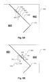
- FIG. 6A illustrates an edge search and pixel replacement process according to one embodiment of the present invention.
- FIG. 6B illustrates a non-detailed search and pixel replacement process according to one embodiment of the present invention.
- FIG. 7 illustrates an image processing system according to one embodiment of the present invention.
- inventions and advantages of the present invention include a method for error concealment in digital images with moving objects.
- the location of regions with high error are determined and more accurate replacement pixels are generated based on an in-painting technique described below.
- in-painting uses the spatial and temporal pixels around an error region to estimate the pixels with the lowest error to be used as replacement pixels.
- the method described herein may be implemented in an image processing system, for example, as described in more detail below.
- FIG. 3 illustrates an occlusion region and associated error.
- a motion estimator using information from the successive frames may not find a good match in the region that undergoes occlusion.
- occlusion region 211 may result in an error region 220 , where pixel values may need to be replaced to improve the image quality.
- the disclosure below is described in the context of occlusion, it is to be understood that the techniques described herein may also be applied to a region that undergoes uncovering.
- embodiments of the present invention may use motion vector profiles to decide whether to copy information from the foreground or from the background to correct for occlusion errors.
- Image information from the spatial neighborhood may be used to replace information in the error region and improve image quality.
- FIG. 4 illustrates a method of concealing errors in a digital image according to one embodiment of the present invention.
- a current frame, a previous frame, and a motion vector may be used to determine the location of pixels in the current frame with unacceptably high error.
- both the current frame and the previous frame may comprise arrays of pixels and corresponding pixel values.
- Each pixel may further have an associated motion vector.
- Motion vectors may specify the motion of one or more objects represented in each frame.
- the previous frame may include motion vectors that specify a velocity vector for each pixel. If an object is moving across the image between frames, the motion vector may have large values for pixels that are near edges of the object, for example. Other pixels may have smaller or even zero motion vector values in other parts of the image.
- motion vectors may be used to generate reference values. For example, at 401 , reference values are generated based on pixel values in a previous frame modified by the associated motion vectors. The result may include an array of reference values that may be compared to the current frame. At 402 , pixel values in the current frame are compared to the reference values. For example, if the pixel values in the current frame meet (e.g., match) the reference values, then the motion vectors may be a satisfactory representation of the movement of the object across the image.
- a pixel value in the current frame does not meet (e.g., differs from) a corresponding reference value (e.g., a value derived from the same pixel in the previous frame)
- the motion vector may not be a valid representation of the movement of the object across the screen.
- a pixel value in the current frame differs from a corresponding reference value by an amount greater than a predefined threshold, which may be set by performance requirements, for example, then the motion vector is deemed invalid and the pixel in the current frame is replaced according to the process described below.
- the comparison produces difference values for some or all pixels in the current frame based on the pixel values in the previous frame and the associated motion vectors.
- the comparison may include calculating the sum of absolute values of differences (“SAD values”) between the pixel values in the current frame and the reference values.
- SAD values sum of absolute values of differences
- the system determines if the difference between the pixel value in the current frame and the reference value is greater than (or equal to) a threshold. If not, then the motion vector is deemed valid and no errors are corrected (i.e., error concealment may not be required). If the difference is greater than (or equal to) a threshold for any pixel, then the system determines if the location of the erroneous pixel (the pixel having an associated invalid motion vector) is on an object edge at 404 .
- Embodiments of the present invention may search for potential replacement pixels differently depending upon whether or not the erroneous pixel is located on the edge of an object in the image.
- the system may perform a search of pixel values in the current frame along the edge (sometimes referred to as a detailed region) for a replacement pixel value at 406 . If the error pixel location is not on an edge, then the system may perform a search of pixel values in a region adjacent to the edge (sometimes referred to as a non-detailed region or texture region) for the replacement pixel value at 407 .
- FIG. 5 illustrates a detailed example process for error concealment according to one embodiment of the present invention.
- a current frame, a previous frame, and a motion vector are received.
- a SAD calculation is performed and the result is compared against a threshold value to determine which motion vectors are valid and which motion vectors are invalid.
- error pixels are compared against an edge mask (described below) to determine if the error pixels are located on an edge.
- the process chooses between an edge search algorithm and a texture search algorithm to conceal the errors. For example, if error pixels are located on an edge, then an edge search algorithm is used. If pixels are not located on an edge, then a texture search algorithm is used.
- the direction of the edge is determined for an edge search.
- a first candidate pixel on the edge adjacent to and outside the error region is analyzed.
- the error region is region of the image where pixel values in the current frame differ from corresponding reference values by an amount greater than a threshold.
- a defined region of pixels e.g., N ⁇ M
- a SAD calculation is performed on the first candidate pixel and the current frame pixel (or defined region of pixels).
- the result is weighted based on location as described in more detail below.
- the best match may be the best weighted SAD match across a predefined number of pixels/pixel regions along the edge, for example. If the best match is not found, operations in connection with 506 , 507 , and 508 are repeated.
- the best match is copied to replace the error pixel. Referring back to 504 , if the error pixel is not on an edge, the process proceeds to 512 rather than 505 .
- a first candidate pixel in a region off and adjacent to the edge outside the error region is analyzed. As described in more detail below, at least two alternative embodiments may be used for determining if candidate pixels are suitable replacement pixels.
- a SAD best match search may be performed across a texture region at 513 .
- the best match pixel in the textured region off the edge may be copied to replace the error pixel at 510 .
- the distributions of texture regions may be analyzed and the error pixel may be assigned a mean or average value of the distributions at 514 . The above process is further explained in FIGS. 6A and 6B .
- FIG. 6A illustrates an edge search and pixel replacement process according to one embodiment of the present invention.
- This example shows a portion of a frame 603 including an edge 610 and an error region 620 .
- Error region 620 may be a region where pixels located in the region have corresponding invalid motion vectors, for example.
- the process for concealing the error region 620 may include receiving a current frame, a previous frame, and a motion vector for each pixel in the previous frame, and the error region may be determined by comparing a SAD calculation on each of the pixels in the previous frame interpolated using an associated motion vector.
- FIG. 6A illustrates the use of edge based continuity to fill in the information for the detailed edge region from surrounding detailed edge regions.
- a block of pixels may be replaced together.
- the patch kernel size may be programmable.
- the patch kernel size may be set to 11 ⁇ 5 pixels, but in other embodiments the size can be either smaller or larger than this size.
- the edge 610 is projected across the error region 620 , and an error pixel at 621 on edge 610 may be replaced by searching along the edge 610 for a replacement in a region outside the error region 620 .
- Data representing the edge 610 may be analyzed and the direction of the edge 610 may be computed in the error region 620 (e.g., using a linear projection).
- the edge 610 may be represented by an edge mask.
- An edge mask may be derived from the image by extracting boundaries of objects in the image. Edge locations in a frame of an image may be represented as white areas and non-edge locations may be represented as black areas, for example. Edges in an edge mask may be one pixel in width or even several pixels in width, for example.
- An edge mask may be used to determine if a particular error pixel is on an edge or not. If an error pixel is located on an edge pixel in an edge mask, then the error pixel location may be considered on an edge. Similarly, if an error pixel is located off an edge pixel (on a non-edge pixel location) in an edge mask, then the error pixel location may be considered not on an edge.
- the system may define a region (or patch) centered on the target pixel that needs to be filled or replaced (e.g., an 11 ⁇ 5 block of pixels).
- the closest match around the error region along the edge direction is chosen as the candidate match. This ensures the edge continuity in the target pixel that needs to be filled.
- the error match criterion may be a function of the minimum SAD error, and optionally, the distance from the error region to be filled (e.g., the target region), for example.
- the distance criterion may be used to ensure homogeneity of pixels in the error corrected frame (e.g., the interpolated frame). If an error is filled using pixels located far away, then the interpolated frame may have a discontinuity. In the example of FIG.
- the system searches along edge 610 and may perform a SAD match with pixels at 622 , 623 , and 624 .
- the match may be obtained from the edge pixel at 623 .
- each match may be weighted based on the distance from the error pixel to be replaced, where candidate pixels located closer to the error pixel are weighted more than candidate pixels located farther away.
- An example weighting may be as follows: SAD, SAD/2, SAD/4, etc. . . . , where the SAD values are attenuated more if the pixels are farther away from the error pixel. This weighting is optional, and may not be included in some embodiments.
- the edge pixel at 623 may be weighted less than the edge pixel at 622 .
- the match at 623 may be sufficiently better such that it overcomes the weighting. Accordingly, the pixel at 623 is selected as the best replacement, and it may be copied to replace pixel 621 as illustrated at 625 . This process may be repeated (e.g., from opposite sides of the error region) until the edge 610 is filled in across the error region 620 .
- FIG. 6B illustrates a non-detailed search and pixel replacement process according to one embodiment of the present invention.
- the system may perform a search of pixel values in the current frame in a region adjacent to the edge 610 for the replacement pixel value.
- the system may search for pixels in a non-detailed (e.g., textured) region off the edge 610 near the error pixel 631 .
- a pixel at 632 adjacent to and off of edge 610 may be a good match and may be copied to replace the error pixel at 631 .
- a pixel at 634 adjacent to and off of edge 610 may be a good match and may be copied to replace the error pixel at 633 .
- the error pixel location is not on the edge, then error pixels on a first side of the edge are replaced with a foreground pixel, and error pixels on a second side of the edge are replaced with a background pixel.
- the foreground is a non-detailed or textured region of the object in motion
- the background is a non-detailed or textured region that the object is passing over.
- error concealment in non-detailed regions may be performed alternatively using a matching approach or another approach based on the distribution of values across a defined region.
- a suitable non-detailed region may be determined using a SAD match calculation across a defined region of pixels (e.g., an 11 ⁇ 5 region as above). In this case, a region including current pixels around the error pixel location is specified and a SAD match between the current pixels and pixels in a textured region is performed to find a best match.
- the system may replace error pixels by analyzing the distribution of pixels. For example, a region of pixels (e.g., 11 ⁇ 5) may be defined around the error pixel. The distribution of pixels across the region centered on the error pixel may be determined. The value of the error pixel may be assigned the mean or average of the distribution. If the distribution includes multiple modalities (e.g., if the distribution is a bi-modal distribution with two peaks), then the system may determine the number of modalities and select the modality having the largest number of values. The mean or average is then based on the selected modality.
- a region of pixels e.g., 11 ⁇ 5
- the distribution of pixels across the region centered on the error pixel may be determined.
- the value of the error pixel may be assigned the mean or average of the distribution. If the distribution includes multiple modalities (e.g., if the distribution is a bi-modal distribution with two peaks), then the system may determine the number of modalities and select the modality having the largest number of values. The mean
- the system may use a Markovian model for texture synthesis to replace error pixels.
- a non-detailed region may contain specific texture.
- the texture can be random or have a periodicity. Since periodic texture is often not a non-detailed error region, it can be assumed that the texture is random.
- a probable value for the target error pixel may be calculated based on the available pixels that are not part of the error region and has already been filled in. The probability distribution function of the surrounding pixels in a defined region centered at the target error pixel is computed.
- a Gaussian distribution may be assumed for simplicity. In this implementation, the mean of the Gaussian distribution may be taken as the target value that needs to be filled in.
- Embodiments of the present invention may be implemented using a variety of hardware architectures.
- embodiments of the present invention may be implemented in software executed on a computer using one or more processors, in a digital signal processor, or as a custom application specific integrated circuit.
- One application specific hardware implementation may be in a compensation and dynamic averaging block of an image processing system disclosed in U.S. patent application Ser. No. 12/400,207, entitled “Filter Bank Based Phase Correlation Architecture for Motion Estimation”, filed Mar. 9, 2009, the entire disclosure of which is incorporated herein by reference.
- FIG. 7 illustrates an image processing system according to an embodiment of the invention.
- Image processing system 700 includes front end 701 , video format conversion and processing block 702 , motion compensation and picture rate conversion block 703 , timing controller and display driver block 704 , and an LCD 705 .
- Front end 701 includes input capture circuits such as analog-to-digital converters and demodulators, for example, to receive transmitted image data in a transmitted format and produce digital image data.
- Video format conversion and processing block 702 performs preprocessing including converting the digital image data into a native system format. The output of the video format conversion and processing block 702 are uncompensated frames of digital image data.
- Motion compensation and picture rate conversion block 703 compensates for errors generated, for example, when an object moves between two frames as described above.
- the output of motion compensation and picture rate conversion block 703 are compensated frames of digital image data.
- the compensated frames may be received by timing controller and display driver block 704 , which drives an LCD 705 . Further details of each of the above blocks are described in U.S. patent application Ser. No. 12/400,207, entitled “Filter Bank Based Phase Correlation Architecture for Motion Estimation” mentioned above.
Abstract
Description
Claims (20)
Priority Applications (2)
| Application Number | Priority Date | Filing Date | Title |
|---|---|---|---|
| US12/574,078 US8509552B1 (en) | 2009-03-09 | 2009-10-06 | Digital image processing error concealment method |
| US13/951,533 US8787696B1 (en) | 2009-03-09 | 2013-07-26 | Method and apparatus for replacing a block of pixels in a digital image frame to conceal an error associated with the block of pixels |
Applications Claiming Priority (3)
| Application Number | Priority Date | Filing Date | Title |
|---|---|---|---|
| US12/400,207 US8233730B1 (en) | 2008-04-22 | 2009-03-09 | Filter bank based phase correlation architecture for motion estimation |
| US16560709P | 2009-04-01 | 2009-04-01 | |
| US12/574,078 US8509552B1 (en) | 2009-03-09 | 2009-10-06 | Digital image processing error concealment method |
Related Parent Applications (1)
| Application Number | Title | Priority Date | Filing Date |
|---|---|---|---|
| US12/400,207 Continuation-In-Part US8233730B1 (en) | 2008-04-22 | 2009-03-09 | Filter bank based phase correlation architecture for motion estimation |
Related Child Applications (1)
| Application Number | Title | Priority Date | Filing Date |
|---|---|---|---|
| US13/951,533 Continuation US8787696B1 (en) | 2009-03-09 | 2013-07-26 | Method and apparatus for replacing a block of pixels in a digital image frame to conceal an error associated with the block of pixels |
Publications (1)
| Publication Number | Publication Date |
|---|---|
| US8509552B1 true US8509552B1 (en) | 2013-08-13 |
Family
ID=48916692
Family Applications (2)
| Application Number | Title | Priority Date | Filing Date |
|---|---|---|---|
| US12/574,078 Active 2031-07-17 US8509552B1 (en) | 2009-03-09 | 2009-10-06 | Digital image processing error concealment method |
| US13/951,533 Active US8787696B1 (en) | 2009-03-09 | 2013-07-26 | Method and apparatus for replacing a block of pixels in a digital image frame to conceal an error associated with the block of pixels |
Family Applications After (1)
| Application Number | Title | Priority Date | Filing Date |
|---|---|---|---|
| US13/951,533 Active US8787696B1 (en) | 2009-03-09 | 2013-07-26 | Method and apparatus for replacing a block of pixels in a digital image frame to conceal an error associated with the block of pixels |
Country Status (1)
| Country | Link |
|---|---|
| US (2) | US8509552B1 (en) |
Cited By (4)
| Publication number | Priority date | Publication date | Assignee | Title |
|---|---|---|---|---|
| US20100277477A1 (en) * | 2009-05-01 | 2010-11-04 | Microsoft Corporation | Modeling Anisotropic Surface Reflectance with Microfacet Synthesis |
| US20160112641A1 (en) * | 2014-10-21 | 2016-04-21 | Bae Systems Information And Electronic Systems Integration Inc. | Frame registration for imaging sensors in motion |
| US20170223383A1 (en) * | 2016-01-28 | 2017-08-03 | Interra Systems, Inc. | Methods and systems for detection of artifacts in a video after error concealment |
| CN110062219A (en) * | 2019-03-12 | 2019-07-26 | 杭州电子科技大学 | In conjunction with virtual viewpoint rendering 3D-HEVC entire frame loss error concealing method |
Citations (4)
| Publication number | Priority date | Publication date | Assignee | Title |
|---|---|---|---|---|
| US5581308A (en) * | 1995-03-18 | 1996-12-03 | Daewoo Electronics Co., Ltd. | Method and apparatus for determining true motion vectors for selected pixels |
| US5982441A (en) * | 1996-01-12 | 1999-11-09 | Iterated Systems, Inc. | System and method for representing a video sequence |
| US7224731B2 (en) * | 2002-06-28 | 2007-05-29 | Microsoft Corporation | Motion estimation/compensation for screen capture video |
| US8064522B2 (en) * | 2004-03-01 | 2011-11-22 | Sony Corporation | Motion-vector detecting device, motion-vector detecting method, and computer program |
Family Cites Families (5)
| Publication number | Priority date | Publication date | Assignee | Title |
|---|---|---|---|---|
| US6005916A (en) | 1992-10-14 | 1999-12-21 | Techniscan, Inc. | Apparatus and method for imaging with wavefields using inverse scattering techniques |
| US7841982B2 (en) | 1995-06-22 | 2010-11-30 | Techniscan, Inc. | Apparatus and method for imaging objects with wavefields |
| US6167155A (en) * | 1997-07-28 | 2000-12-26 | Physical Optics Corporation | Method of isomorphic singular manifold projection and still/video imagery compression |
| US7197074B2 (en) | 2003-02-20 | 2007-03-27 | The Regents Of The University Of California | Phase plane correlation motion vector determination method |
| US7570309B2 (en) | 2005-09-27 | 2009-08-04 | Samsung Electronics Co., Ltd. | Methods for adaptive noise reduction based on global motion estimation |
-
2009
- 2009-10-06 US US12/574,078 patent/US8509552B1/en active Active
-
2013
- 2013-07-26 US US13/951,533 patent/US8787696B1/en active Active
Patent Citations (4)
| Publication number | Priority date | Publication date | Assignee | Title |
|---|---|---|---|---|
| US5581308A (en) * | 1995-03-18 | 1996-12-03 | Daewoo Electronics Co., Ltd. | Method and apparatus for determining true motion vectors for selected pixels |
| US5982441A (en) * | 1996-01-12 | 1999-11-09 | Iterated Systems, Inc. | System and method for representing a video sequence |
| US7224731B2 (en) * | 2002-06-28 | 2007-05-29 | Microsoft Corporation | Motion estimation/compensation for screen capture video |
| US8064522B2 (en) * | 2004-03-01 | 2011-11-22 | Sony Corporation | Motion-vector detecting device, motion-vector detecting method, and computer program |
Non-Patent Citations (4)
| Title |
|---|
| A. Criminisi et al., "Region Filling and Object Removal by Exemplar-Based Image Inpainting," IEEE Transactions on Image Processing, vol. 13, No. 9, Sep. 2004. |
| M. Bertalmio et al., "Image Inpainting," in Proc. ACM-SIGGRAPH, 2000, pp. 417-424. |
| S. Kumar et al., "Spatio-Temporal Texture Synthesis and Image Inpainting for Video Applications," IEEE Conference on Image Processing, Sep. 2005, vol. 2, pp. 85-88. |
| T. F. Chan et al., "Variational Image Inpainting," ftp://ftp.math.ucla.edu/pub/camreport/cam02-63.pdf, Dec. 2002. |
Cited By (8)
| Publication number | Priority date | Publication date | Assignee | Title |
|---|---|---|---|---|
| US20100277477A1 (en) * | 2009-05-01 | 2010-11-04 | Microsoft Corporation | Modeling Anisotropic Surface Reflectance with Microfacet Synthesis |
| US9098945B2 (en) * | 2009-05-01 | 2015-08-04 | Microsoft Technology Licensing, Llc | Modeling anisotropic surface reflectance with microfacet synthesis |
| US20160112641A1 (en) * | 2014-10-21 | 2016-04-21 | Bae Systems Information And Electronic Systems Integration Inc. | Frame registration for imaging sensors in motion |
| US9900509B2 (en) * | 2014-10-21 | 2018-02-20 | Bae Systems Information And Electronic Systems Integration Inc. | Frame registration for imaging sensors in motion |
| US20170223383A1 (en) * | 2016-01-28 | 2017-08-03 | Interra Systems, Inc. | Methods and systems for detection of artifacts in a video after error concealment |
| US10275894B2 (en) * | 2016-01-28 | 2019-04-30 | Interra Systems | Methods and systems for detection of artifacts in a video after error concealment |
| CN110062219A (en) * | 2019-03-12 | 2019-07-26 | 杭州电子科技大学 | In conjunction with virtual viewpoint rendering 3D-HEVC entire frame loss error concealing method |
| CN110062219B (en) * | 2019-03-12 | 2020-11-06 | 杭州电子科技大学 | 3D-HEVC (high efficiency video coding) whole frame loss error concealment method by combining virtual viewpoint drawing |
Also Published As
| Publication number | Publication date |
|---|---|
| US8787696B1 (en) | 2014-07-22 |
Similar Documents
| Publication | Publication Date | Title |
|---|---|---|
| JP4997281B2 (en) | Method for determining estimated motion vector in image, computer program, and display device | |
| US6625333B1 (en) | Method for temporal interpolation of an image sequence using object-based image analysis | |
| JP5657391B2 (en) | Image interpolation to reduce halo | |
| US7796191B1 (en) | Edge-preserving vertical interpolation | |
| EP1549047B1 (en) | Robust camera pan vector estimation using iterative center of mass | |
| US20110134315A1 (en) | Bi-Directional, Local and Global Motion Estimation Based Frame Rate Conversion | |
| JP2003533800A (en) | Motion estimator to reduce halo in MC upconversion | |
| US8189105B2 (en) | Systems and methods of motion and edge adaptive processing including motion compensation features | |
| US8571114B2 (en) | Sparse geometry for super resolution video processing | |
| KR20070069615A (en) | Motion estimator and motion estimating method | |
| KR20070003206A (en) | Hierarchical motion estimating method and ultrasound image display device using the same | |
| US8406305B2 (en) | Method and system for creating an interpolated image using up-conversion vector with uncovering-covering detection | |
| KR20070063304A (en) | Motion estimator and motion estimating method | |
| US9674483B2 (en) | Method and device for generating a motion-compensated video frame | |
| US8787696B1 (en) | Method and apparatus for replacing a block of pixels in a digital image frame to conceal an error associated with the block of pixels | |
| US20120176536A1 (en) | Adaptive Frame Rate Conversion | |
| WO2012066866A1 (en) | Motion vector detection device, motion vector detection method, frame interpolation device, and frame interpolation method | |
| US9106926B1 (en) | Using double confirmation of motion vectors to determine occluded regions in images | |
| JP2009295029A (en) | Moving quantity detection device and moving quantity detection method | |
| US8805101B2 (en) | Converting the frame rate of video streams | |
| TWI425840B (en) | Robust Adaptive Decoupling Device and Method for Displacement Compensation Using Overlapping Blocks | |
| Biswas et al. | On handling of occlusion for frame rate up-conversion using video in-painting | |
| KR20100062301A (en) | Apparatus and method for estimating motion by block segmentation and combination | |
| Vinolee et al. | Motion interpolation using interframe coding for block motion picture | |
| KR20140134907A (en) | Apparatus and method for Motion Compensated Interpolation of moving caption region |
Legal Events
| Date | Code | Title | Description |
|---|---|---|---|
| AS | Assignment |
Owner name: MARVELL INTERNATIONAL LTD., BERMUDA Free format text: ASSIGNMENT OF ASSIGNORS INTEREST;ASSIGNOR:MARVELL SEMICONDUCTOR, INC.;REEL/FRAME:023388/0800 Effective date: 20091006 Owner name: MARVELL SEMICONDUCTOR, INC., CALIFORNIA Free format text: ASSIGNMENT OF ASSIGNORS INTEREST;ASSIGNOR:BISWAS, MAINAK;REEL/FRAME:023388/0727 Effective date: 20091005 Owner name: MARVELL INDIA PVT. LTD., INDIA Free format text: ASSIGNMENT OF ASSIGNORS INTEREST;ASSIGNOR:NAMBOODIRI, VIPIN;REEL/FRAME:023388/0754 Effective date: 20091006 Owner name: MARVELL INTERNATIONAL LTD., BERMUDA Free format text: ASSIGNMENT OF ASSIGNORS INTEREST;ASSIGNOR:MARVELL INDIA PVT. LTD.;REEL/FRAME:023388/0895 Effective date: 20091006 |
|
| STCF | Information on status: patent grant |
Free format text: PATENTED CASE |
|
| FPAY | Fee payment |
Year of fee payment: 4 |
|
| AS | Assignment |
Owner name: SYNAPTICS LLC, SWITZERLAND Free format text: ASSIGNMENT OF ASSIGNORS INTEREST;ASSIGNOR:MARVELL INTERNATIONAL LTD.;REEL/FRAME:043853/0827 Effective date: 20170611 Owner name: SYNAPTICS INCORPORATED, CALIFORNIA Free format text: ASSIGNMENT OF ASSIGNORS INTEREST;ASSIGNOR:MARVELL INTERNATIONAL LTD.;REEL/FRAME:043853/0827 Effective date: 20170611 |
|
| AS | Assignment |
Owner name: WELLS FARGO BANK, NATIONAL ASSOCIATION, NORTH CAROLINA Free format text: SECURITY INTEREST;ASSIGNOR:SYNAPTICS INCORPORATED;REEL/FRAME:044037/0896 Effective date: 20170927 Owner name: WELLS FARGO BANK, NATIONAL ASSOCIATION, NORTH CARO Free format text: SECURITY INTEREST;ASSIGNOR:SYNAPTICS INCORPORATED;REEL/FRAME:044037/0896 Effective date: 20170927 |
|
| MAFP | Maintenance fee payment |
Free format text: PAYMENT OF MAINTENANCE FEE, 8TH YEAR, LARGE ENTITY (ORIGINAL EVENT CODE: M1552); ENTITY STATUS OF PATENT OWNER: LARGE ENTITY Year of fee payment: 8 |