US8516271B2 - Securing non-volatile memory regions - Google Patents
Securing non-volatile memory regions Download PDFInfo
- Publication number
- US8516271B2 US8516271B2 US13/046,381 US201113046381A US8516271B2 US 8516271 B2 US8516271 B2 US 8516271B2 US 201113046381 A US201113046381 A US 201113046381A US 8516271 B2 US8516271 B2 US 8516271B2
- Authority
- US
- United States
- Prior art keywords
- key
- region
- data
- volatile memory
- cache
- Prior art date
- Legal status (The legal status is an assumption and is not a legal conclusion. Google has not performed a legal analysis and makes no representation as to the accuracy of the status listed.)
- Active, expires
Links
Images


Classifications
-
- G—PHYSICS
- G06—COMPUTING; CALCULATING OR COUNTING
- G06F—ELECTRIC DIGITAL DATA PROCESSING
- G06F12/00—Accessing, addressing or allocating within memory systems or architectures
- G06F12/02—Addressing or allocation; Relocation
- G06F12/0223—User address space allocation, e.g. contiguous or non contiguous base addressing
- G06F12/023—Free address space management
- G06F12/0238—Memory management in non-volatile memory, e.g. resistive RAM or ferroelectric memory
- G06F12/0246—Memory management in non-volatile memory, e.g. resistive RAM or ferroelectric memory in block erasable memory, e.g. flash memory
-
- G—PHYSICS
- G06—COMPUTING; CALCULATING OR COUNTING
- G06F—ELECTRIC DIGITAL DATA PROCESSING
- G06F12/00—Accessing, addressing or allocating within memory systems or architectures
- G06F12/14—Protection against unauthorised use of memory or access to memory
- G06F12/1416—Protection against unauthorised use of memory or access to memory by checking the object accessibility, e.g. type of access defined by the memory independently of subject rights
- G06F12/1425—Protection against unauthorised use of memory or access to memory by checking the object accessibility, e.g. type of access defined by the memory independently of subject rights the protection being physical, e.g. cell, word, block
- G06F12/1441—Protection against unauthorised use of memory or access to memory by checking the object accessibility, e.g. type of access defined by the memory independently of subject rights the protection being physical, e.g. cell, word, block for a range
-
- G—PHYSICS
- G06—COMPUTING; CALCULATING OR COUNTING
- G06F—ELECTRIC DIGITAL DATA PROCESSING
- G06F12/00—Accessing, addressing or allocating within memory systems or architectures
- G06F12/14—Protection against unauthorised use of memory or access to memory
- G06F12/1458—Protection against unauthorised use of memory or access to memory by checking the subject access rights
- G06F12/1466—Key-lock mechanism
-
- G—PHYSICS
- G06—COMPUTING; CALCULATING OR COUNTING
- G06F—ELECTRIC DIGITAL DATA PROCESSING
- G06F2212/00—Indexing scheme relating to accessing, addressing or allocation within memory systems or architectures
- G06F2212/22—Employing cache memory using specific memory technology
- G06F2212/225—Hybrid cache memory, e.g. having both volatile and non-volatile portions
Definitions
- NVM Non-volatile memory
- DRAM dynamic random access memory
- NVM acting as a secondary storage backed by a DRAM buffer. It is expected that NVM may even replace DRAM in future microprocessor and other processing systems.
- the resilience properties of NVM such as the ability for data stored in NVM to persist after power is removed or a system crash occurs, is one of the driving factors for including NVM in modern memory architectures.
- FIG. 1 is a block diagram of an example processing node including an example cache controller to secure regions of an example NVM.
- FIG. 2 illustrates an example ephemeral region and an example persistent region included in the NVM of FIG. 1 .
- FIG. 3 is a block diagram of an example implementation of the processing node of FIG. 1 , which illustrates an example implementation of the cache controller, as well as an example key generator and an example key table that may be used to secure regions of the NVM.
- FIG. 4 is a block diagram illustrating an example key retrieval processing performed by the cache controller in the example processing node of FIGS. 1 and/or 3 .
- FIG. 5 is a block diagram of an example recovery service that can be used to recover data stored in persistent regions of the NVM of FIGS. 1-3 .
- FIG. 6 is a flowchart representative of an example process to perform cache line filling from an NVM that may be used to implement the example cache controller of FIGS. 1 and/or 3 .
- FIG. 7 is a flowchart representative of an example process to perform cache line writing to an NVM that may be used to implement the example cache controller of FIGS. 1 and/or 3 .
- FIG. 8 is a flowchart representative of an example process to perform key generation that may be used to implement the example key generator of FIG. 3 .
- FIG. 9 is a flowchart representative of an example process to perform key generation that may be used to implement the example recovery service of FIG. 5 .
- FIG. 10 is a flowchart representative of an example process to recover data from a persistent region of NVM that may be used to implement the example recovery service of FIG. 5 .
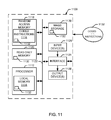
- FIG. 11 is a block diagram of an example processing system that may execute example machine readable instructions to implement one or more of the processes of FIGS. 6-9 and/or 10 to implement the example processing node of FIGS. 1 and/or 3 , the example cache controller of FIGS. 1 and/or 3 , the example key generator of FIG. 3 and/or the example recovery service of FIG. 5 .
- Example methods, apparatus and articles of manufacture to secure NVM regions are disclosed herein. Due, at least in part, to the ability of data stored in NVM to persist after power is removed or a system crash occurs, NVM is becoming more prevalent in the memory architectures of modern processing systems. However, such data resiliency can make systems employing NVM vulnerable to attacks and data leaks as more of the memory space is able to retain stored data indefinitely, or at least for substantial periods of time after power is removed from the system.
- Example methods, apparatus and articles of manufacture disclosed herein are able to secure NVM regions of memory such that data is unrecoverable when stored in NVM regions that are designated to contain data that should not persist after power loss, whereas data is recoverable when stored in NVM regions that are designated to contain data that should persist after power loss.
- a dual-key approach is used to encrypt and decrypt data transferred between cache lines and an NVM.
- a process is assigned or otherwise associated with at least two different encryption/decryption key pairs.
- One of the key pairs is used to encrypt and decrypt data that is transferred for the process between a cache line and a region of the NVM designated to be ephemeral (e.g., a region that is to contain data that should not survive after loss of power).
- Another of the key pairs is used to encrypt and decrypt data that is transferred for the process between a cache line and a different region of the NVM designated to be persistent (e.g., a region that is to contain data that should be recoverable after loss of power).
- data stored in an ephemeral region of the NVM is retrievable using only the decryption key included in the process's ephemeral region key pair.
- data stored in a persistent region of the NVM is retrievable using either the decryption key included in the process's persistent region key pair, or another (e.g., different) decryption key maintained by, for example, a recovery service.
- the key pairs associated with a process are stored in volatile memory and, thus, become lost after, for example, a power loss or a system crash.
- example methods, apparatus and articles of manufacture disclosed herein can secure regions of the NVM by preventing recovery of data stored in ephemeral regions of the NVM after an intentional or unintentional loss of power, but permitting recovery of data stored in persistent regions only by entities (e.g., such as a recovery service) possessing an appropriate recovery (e.g., decryption) key.
- entities e.g., such as a recovery service
- FIG. 1 a block diagram of an example processing node 100 capable of securing regions of an NVM in accordance with the example methods, apparatus and articles of manufacture disclosed herein is illustrated in FIG. 1 .
- the example processing node 100 can correspond to a microprocessor system or other physical and/or virtual processing system, device, etc.
- the processing node 100 includes one or more example processor cores 105 A-B, and an example NVM 110 to implement, at least in part, main memory to store data for one or more processes executing on the processor core(s) 105 A-B.
- the processing node 100 also includes an example last level cache 115 between the processor core(s) 105 A-B and the NVM 110 to cache data read from or to be written to the NVM 110 .
- Zero or more intermediate level cache(s) 120 A-B can also be included in the processing node 100 , as shown in FIG. 1 .
- the NVM 110 of FIG. 1 further includes an example secure cache controller 125 .
- the processor core(s) 105 A-B can be implemented by any type of processor core, central processing unit (CPU), etc., such as one or more of the processors 1112 included in the example processing system 1100 of FIG. 11 .
- the NVM 110 can be implemented by any type of non-volatile memory, such as the example non-volatile memory 1120 included in the processing system 1100 of FIG. 11 .
- the processing system 1100 of FIG. 11 is described in greater detail below.
- the intermediate level cache(s) 120 A-B can be implemented using any type of caching technology.
- the intermediate level cache(s) 120 A-B can be organized into cache lines, where each cache line can store data from a memory location in the NVM 110 .
- each cache line also includes a tag containing an address to identify (at least in part) where the cached data is stored in the NVM 110 .
- the last level cache 115 is also organized into cache lines, each containing a data part to store data from a memory location in the NVM 110 , and a tag containing an address for the data.
- the last level cache 115 is modified such that one or more cache lines further include, or are otherwise associated with, a tag extension or other information field to enable securing of regions of the NVM 110 , as described herein.
- data stored in the NVM 110 is retained after an intentional or unintentional loss of power (e.g., corresponding to a system reboot, a system crash, loss of main power, etc.).
- data stored in main memory is lost after power to the system is removed.
- a process stack and/or other critical portions of process data are not accessible, thereby preventing a malicious attacker from gaining access to this data and, for example, reverse-engineering process algorithms, retrieving private data, etc.
- NVM such as the NVM 110
- DRAM dynamic random access memory
- main memory main memory
- DRAM dynamic random access memory
- main memory main memory
- data resiliency also means that the data stored in an NVM, such as the NVM 110 , can be susceptible to malicious attacks for much longer periods of time than data stored in DRAM-based memories (and other volatile memories).
- the secure cache controller 125 secures regions of the NVM 110 to permit retrieval of portions of process data to be used to recover a process after an intentional or unintentional loss of power, but to prevent retrieval of data that is not used for process recovery.
- the secure cache controller 125 employs a multi-key (e.g., dual-key) approach to encrypt and decrypt data transferred between cache lines of the last level cache 115 and the NVM 110 .
- the secure cache controller 125 implements this multi-key approach by employing a first key pair (e.g., an ephemeral region key pair) to encrypt and decrypt data that is transferred for a process between a cache line of the last level cache 115 and a region of the NVM 110 designated to be an ephemeral region (also referred to as a disposable region of the NVM 110 ).
- a first key pair e.g., an ephemeral region key pair
- the secure cache controller 125 also employs a second key pair (e.g., a persistent region key pair), which is different from the first key pair, to encrypt and decrypt data that is transferred for the process between a cache line of the last level cache 115 and a different region of the NVM 110 designated to be a persistent region (also referred to as a recoverable region of the NVM 110 ).
- a second key pair e.g., a persistent region key pair
- data stored in an ephemeral region of the NVM 110 is retrievable using only the decryption key included in the ephemeral region key pair, whereas data is stored in the persistent region is retrievable using a decryption key included in the persistent region key pair, or another (e.g., different) decryption key maintained by, for example, another processing node implementing a recovery service.
- Example ephemeral and persistent regions designated or otherwise included in the NVM 110 of FIG. 1 are illustrated in FIG. 2 .
- the NVM 110 includes an example ephemeral region 205 and an example persistent region 210 .
- the ephemeral region 205 and/or the persistent region 210 may be specific to a particular process or shared among multiple processes.
- the ephemeral region 205 of the NVM 110 stores data that is not to be used to recover a state of a process after an intentional or unintentional loss of power loss.
- the ephemeral region 205 can include a process stack 215 , an ephemeral heap 220 (e.g., containing portions of a process heap that are transient in nature), etc.
- the persistent region 210 of the NVM 110 stores data that is to be used to recover the state of the process after an intentional or unintentional loss of power.
- the persistent region 210 can include a .bss region 225 (e.g., also referred to as a block started by symbol region, which contains statically-allocated variables for the process), a persistent heap 230 (e.g., containing portions of the process heap that represent, at least in part, the state of the process), etc.
- FIG. 3 An example implementation of the processing node 100 of FIG. 1 that illustrates an example implementation of the secure cache controller 125 is illustrated in FIG. 3 . Similar elements in FIGS. 1 , 2 and 3 are labeled with the same reference numerals. Like the example of FIG. 1 , the processing node 100 of FIG. 3 includes the NVM 110 and the last level cache 115 . The NVM 110 includes the ephemeral region 205 and the persistent region 210 for storing process data for a process executing on the processing node 100 .
- the processing node 100 includes an example key generator 305 to generate encryption and decryption key pairs to encrypt and decrypt data to be exchanged between cache lines of the last level cache 115 and the NVM 110 .
- the key generator 305 can generate keys in accordance with any public key encryption algorithm (e.g., such as, but not limited to, the pretty good privacy (PGP) algorithm).
- PGP pretty good privacy
- public key encryption data is encrypted using a public key that can be shared publicly, but is decrypted using a private key typically known only to the key owner.
- PGP pretty good privacy
- public key encryption to generate an encryption/decryption key pair, the key generator 305 generates a public/private key pair, and uses the public key to determine the encryption key, and the private key to determine the decryption key.
- the NVM 110 supports multi-tenancy in which multiple processes can share the same physical address space in the NVM 110 .
- the key generator 305 generates different (e.g., unique) public/private key pairs to determine different (e.g., unique) encryption/decryption key pairs to be assigned to (or otherwise associated with) different processes executing on the processing node 100 . In this way, data stored in the NVM 110 for one process is secure from snooping or other unauthorized retrieval by another process.
- the key generator 305 can determine common public and private keys to be used by the processing sharing a particular memory region.
- the key generator 305 can combine, in accordance with the public key encryption in use, the public keys for the processes that are to share a particular memory region. The key generator 305 then uses this common public key to determine a common encryption key for use in encrypting the process data to be stored in this shared memory region. However, the individual decryption keys determined from the individual private keys associated with the processes sharing the memory region can each still be used to decrypt the process data stored in the shared memory region.
- the secure cache controller 125 employs a multi-key approach in which multiple key pairs are associated with a particular process and used to secure respective different regions of the NVM 110 for the process.
- the secure cache controller 125 can use a first encryption/decryption key pair (e.g., also referred to as an ephemeral region key pair) to secure the ephemeral region 205 of the NVM 110 for a particular process, and a second encryption/decryption key pair (e.g., also referred to as a persistent region key pair) to secure the persistent region 210 of the NVM 110 for the particular process.
- a first encryption/decryption key pair e.g., also referred to as an ephemeral region key pair
- a second encryption/decryption key pair e.g., also referred to as a persistent region key pair
- the key generator 305 includes an example ephemeral region key generator 310 to generate ephemeral key pairs for processes executing on the processing node 100 , and a persistent region key generator 315 to generate persistent key pairs for the processes executing on the processing node 100 .
- the ephemeral region key generator 310 generates a public/private key pair for a particular process. The ephemeral region key generator 310 then uses the public key as the encryption key of the ephemeral region key pair for this process, and the private key as the decryption key of the ephemeral region key pair for this process.
- the persistent region key generator 315 generates a different public/private key pair that is used as the encryption and decryption keys, respectively, of the persistent region key pair for the process (e.g., and which is also provided to a recovery service for use as the recovery key pair for this process).
- the persistent region key generator 315 also uses the public/private key pair generated by the ephemeral region key generator 310 to determine the persistent region key pair for this process. For example, the persistent region key generator 315 can also use the private key as the decryption key included in the persistent region key pair for this process. However, to determine the encryption key included in the persistent region key pair for this process, the persistent region key generator 315 combines the public key generated for the process with another public key associated with (e.g., provided by) a recovery service. Thus, data encrypted by the encryption key included in the ephemeral region key pair can be decrypted by only the decryption key included in the ephemeral region key pair.
- data encrypted by the encryption key included in the persistent region key pair can be decrypted by the decryption key included in the persistent region key pair, or by the recovery decryption key (e.g., which may be the same or different from the decryption key of the persistent region key pair) associated with (e.g., maintained by) the recovery service.
- the recovery decryption key e.g., which may be the same or different from the decryption key of the persistent region key pair
- the processing node 100 also includes an example key table memory 320 to store the ephemeral region and persistent region key pairs generated by the key generator 305 for different processes executing on the processing node 100 .
- the key table memory 320 stores the ephemeral region and persistent region key pairs for a particular process in a key table associated with the process.
- the key table memory 320 is implemented by any type of volatile memory (e.g., such as volatile register(s), cache(s), etc.) such that the ephemeral region key pairs for the different processes are lost (e.g., deleted) when the processing node 100 experiences a loss of power.
- the persistent region key pairs for the different processes can also be stored in volatile memory (e.g., in the same key tables as the ephemeral region key pairs) and, thus, lost after a power loss, because data stored in the persistent region(s) 210 of the NVM can also be recovered with the decryption key maintained separately by the recovery service.
- An example of a key table that can be stored in the key table memory 320 is illustrated in FIG. 4 , which is described in greater detail below.
- the secure cache controller 125 includes an example key retriever 325 , an example NVM region security processor 330 and an example cache line buffer 335 .
- the NVM region security processor 330 can implement any public key encryption algorithm, such as the public key encryption algorithm corresponding to the algorithm used by the key generator 305 to generate the encryption/decryption key pairs.
- the NVM region security processor 330 uses an encryption key associated with a process to encrypt data to be written from a cache line of the last level cache 115 to the NVM 110 for the process.
- the NVM region security processor 330 uses a decryption key associated with the process to decrypt data to be read from the NVM 110 and stored, for the process, in a cache line of the last level cache 115 .
- the cache line buffer 335 is provided in the processing node 100 of FIG. 3 as a temporary buffer for use by the NVM region security processor 330 when encrypting and/or decrypting data to be exchanged between the NVM 110 and a cache line of the last level cache 115 .
- the key retriever 325 is included in the processing node 100 to retrieve an appropriate key for use by the NVM region security processor 330 to perform data encryption or decryption. For example, the key retriever 325 retrieves an encryption or decryption key from either the ephemeral region key pair or the persistent region key pair stored in the key table memory 320 for a particular process based on whether the data to be encrypted or decrypted by the NVM region security processor 330 is associated with the ephemeral region 205 or the persistent region 210 of the NVM 110 .
- one or more address bits or lines representing the address of the data in NVM can be used by the key retriever 325 to determine whether the data is associated with (e.g., to be read from or written to) either the ephemeral region 205 or the persistent region 210 of the NVM 110 .
- FIG. 4 A block diagram further illustrating an example key retrieval processing that can be performed by the secure cache controller 125 of FIG. 3 is illustrated in FIG. 4 . Similar elements in FIGS. 3 and 4 are labeled with the same reference numerals.
- the example of FIG. 4 includes an example cache line 405 (e.g., from the last line cache 115 of FIG. 3 ), which is processed by the key retriever 325 to retrieve an appropriate key from the key table memory 320 for use in encrypting or decrypting the data to be exchanged between the cache line 405 and, for example, the NVM 110 .
- the cache line 405 includes an example data section 410 containing data read from or to be written to the NVM 110 , and an example tag containing an address representing (at least in part) a location in the NVM 110 for the data stored in the data section 410 .
- the cache line 405 further includes an example tag extension 415 , which may be, for example, an extension of the tag in the data section 410 , a second tag included in the cache line 405 , a data buffer associated with the cache line 405 , etc.
- the tag extension 415 stores a pointer to an example key table 425 stored in the key table memory 320 for the process whose data is (or is to be) stored in the data section 410 .
- the key table 425 for a particular process e.g., designated as “P” in FIG.
- Each key pair can include two entries (e.g., rows) represented as, for example, one row 430 to store the ephemeral region key pair for the process, and another row 435 to store the persistent region key pair for the process.
- Each key pair includes two entries (e.g., columns) for the keys making up the key pair, which can be represented as, for example, one column 440 to store the encryption key included in the key pair, and another column 445 to store the decryption key included in the key pair.
- the row 430 for P's ephemeral region key pair contains an ephemeral encryption key 450 and an ephemeral decryption key 455 making up the ephemeral region key pair
- the row 435 for P's persistent region key pair contains a persistent encryption key 460 and a persistent decryption key 465 making up the persistent region key pair.
- the key table 425 for a particular process P is stored in a location of the key table memory 320 that is based on a process identifier (ID) representing the process P.
- ID process identifier
- the location of the key table 425 in the key table memory 320 may be determined from a hash and/or mapping of the process ID for the process P.
- the key table pointer stored in the tag extension 420 of the cache line 405 is determined based on P's process ID (e.g., by hashing, mapping, etc. and/or otherwise processing the process ID) to determine the pointer to the key table 425 in the key table memory 320 .
- the run-time architecture specification of the processing node 100 may allocate different ranges of the address space to the ephemeral region(s) 205 and the persistent region(s) 210 .
- the address stored in the tag 415 of the cache line 405 e.g., which represents, at least in part, the location in the NVM 110 of the data stored in the data section 410
- the address stored in the tag 415 of the cache line 405 can be used to determine whether the data stored in the data section 410 is associated with an ephemeral region (e.g., the ephemeral region 205 ) or a persistent region (e.g., the persistent region 210 ) of the NVM 110 .
- the address in the tag 415 (e.g., such as one or more of the most significant bits (MSBs) of the address bits/lines in the tag 415 ) can be used to determine a pointer to either the key pair entry 430 (e.g., corresponding to the ephemeral region 205 of the NVM 110 ) or the key pair entry 435 (e.g., corresponding to the persistent region 210 of the NVM 110 ) of the key table 425 .
- MSBs most significant bits
- the key retriever 325 processes one or more (or all) of the bits/lines 470 of the tag extension 420 containing the key table pointer, along with one or more (or all) of the address bits/lines 475 of the tag 415 , to determine a key pointer 480 .
- the key pointer 480 points to either the row/entry 430 for the ephemeral region key pair stored in the key table 425 , or the row/entry 435 for the persistent region key pair stored in the key table 425 .
- the key retriever 325 selects either the encryption key stored in the encryption key column 440 or the decryption key stored in the decryption key column 445 for the selected key pair entry based on whether the data stored in the data segment 410 of the cache line 405 is to be encrypted or decrypted. In other examples, the key retriever 325 determines the key pointer 480 to point to a specific one of the key entries 450 , 455 , 460 or 465 of the key table 425 .
- FIGS. 1-4 While example manners of implementing the processing node 100 and the secure cache controller 125 have been illustrated in FIGS. 1-4 , one or more of the elements, processes and/or devices illustrated in FIGS. 1-4 may be combined, divided, re-arranged, omitted, eliminated and/or implemented in any other way.
- the example processor core(s) 105 A-B, the example NVM 110 , the example last level cache 115 , the example intermediate level cache(s) 120 A-B, the example key generator 305 , the example ephemeral region key generator 310 , the example persistent region key generator 315 , the example key table memory 320 , the example key retriever 325 , the example NVM region security processor 330 , the example cache line buffer 335 , the example cache line 405 and/or, more generally, the example processing node 100 and/or the example secure cache controller 125 of FIGS. 1-4 may be implemented by hardware, software, firmware and/or any combination of hardware, software and/or firmware.
- any of the example processor core(s) 105 A-B, the example NVM 110 , the example last level cache 115 , the example intermediate level cache(s) 120 A-B, the example key generator 305 , the example ephemeral region key generator 310 , the example persistent region key generator 315 , the example key table memory 320 , the example key retriever 325 , the example NVM region security processor 330 , the example cache line buffer 335 , the example cache line 405 and/or, more generally, the example processing node 100 and/or the example secure cache controller 125 could be implemented by one or more circuit(s), programmable processor(s), application specific integrated circuit(s) (ASIC(s)), programmable logic device(s) (PLD(s)) and/or field programmable logic device(s) (FPLD(s)), etc.
- ASIC application specific integrated circuit
- PLD programmable logic device
- FPLD field programmable logic device
- At least one of the example processing node 100 , the example secure cache controller 125 , the example processor core(s) 105 A-B, the example NVM 110 , the example last level cache 115 , the example intermediate level cache(s) 120 A-B, the example key generator 305 , the example ephemeral region key generator 310 , the example persistent region key generator 315 , the example key table memory 320 , the example key retriever 325 , the example NVM region security processor 330 , the example cache line buffer 335 and/or the example cache line 405 are hereby expressly defined to include a tangible computer readable medium such as a memory, digital versatile disk (DVD), compact disk (CD), etc., storing such software and/or firmware.
- example processing node 100 and/or the example secure cache controller 125 of FIGS. 1-4 may include one or more elements, processes and/or devices in addition to, or instead of, those illustrated in FIGS. 1-4 , and/or may include more than one of any or all of the illustrated elements, processes and devices.
- FIG. 5 An example block diagram of a recovery service 500 that may be used to recover data stored in, for example, the persistent region 210 of the NVM 110 of FIGS. 1-3 is illustrated in FIG. 5 .
- the recovery service 500 can be tied to a particular node, such as the processing node 100 , or included as part of a management service to manage several processing nodes, etc.
- the recovery service 500 can be used to recover data stored in persistent region(s) of an NVM (e.g., such as the persistent region 210 of the NVM 110 ) to enable process states to be recovered and, for example, allow processes to be restarted on a same node and/or migrated to other (e.g., backup) nodes after power loss, system reboot, system crash, etc.
- NVM persistent region(s) of an NVM
- the recovery service 500 includes an example recovery key generator 505 to generate key pairs associated with a particular process (P) at a particular processing node (N) for which data stored in persistent region(s) of an NVM are to be recoverable. Similar to the key generator 305 of FIG. 3 , in some examples, the recovery key generator 505 can generate public/private key pairs for a process (P) in accordance with any public key encryption algorithm. In some examples, the key generator 305 provides the public key generated for the process (P) to its associated processing node (N), such as the processing node 100 , for use in determining a persistent region encryption key for this process, as described above. The associated private key is retained by the recovery service 500 for use as a recovery decryption key for the process (P) to decrypt data encrypted at the node (N) using the persistent region encryption key determined from the public key generated by the recovery key generator 505 .
- the key generator 305 can receive both the recovery encryption key and the recovery decryption key from the processing node 100 , instead of generating the recovery key pair itself.
- the key generator 305 can generate and provide both the recovery encryption key and the recovery decryption key from the processing node 100 , which will use these keys as the persistent region key pair. In these latter two examples, the recover key pair is that same as the persistent region key pair.
- the recovery service 500 also includes an example recovery key table memory 510 to store a recovery key table 515 containing recovery keys for process(es) and node(s) for which data is to be recoverable from persistent regions of an NVM.
- the recovery key table 515 includes entries 520 (e.g., in the form a column 520 ) to store the recovery encryption keys (e.g., such as the public keys) generated or received by the recovery key generator 505 .
- the recovery key table 515 also includes entries 525 (e.g., in the form a column 525 ) to store the associated recovery decryption keys (e.g., such as the private keys) generated or received by the recovery key generator 505 .
- the recovery key table 515 is indexed by process entries 535 (e.g., in the form of a process column 535 ) and node entries 540 (e.g., in the form of a node column 540 ) identifying the particular process and processing node associated with a particular recovery encryption/decryption key pair.
- a row in the recovery key table 515 for a particular processing node 540 and process 535 includes the recovery encryption (e.g., public) key 540 generated or received by the recovery key generator 505 for this node and process, as well as the recovery decryption (e.g., private) key 545 generated or received by the recovery key generator 505 for this node and process.
- the recovery key table 515 also includes boundary information to define the persistent regions in an NVM for a particular process (P) at a particular node (N). For example, such boundary information may be included when the sizes of the ephemeral and/or persistent regions in an NVM are allowed to vary. In examples where the sizes of the ephemeral and persistent regions in an NVM are fixed across processes (P) and nodes (N), such boundary information may be omitted.
- the recovery service 500 of the illustrated example further includes an example data recovery processor 550 to recover, for a particular process (P) at a particular node (N), data stored in a persistent region(s) of an NVM.
- the data recovery processor 550 can receive a request to recover persistent data from an NVM for a particular process (P) at a particular node (N) (e.g., to permit the process P to be restarted or migrated to another node after the particular node N has suffered a power loss or a system crash).
- the data recovery processor 550 Upon receiving the request, the data recovery processor 550 retrieves the recovery decryption key for this process from the appropriate entry 525 of the recovery key table 515 and uses the retrieved key to decrypt the process data stored in a persistent region of the NVM for the process (P) at node (N).
- While an example manner of implementing the recovery service 500 has been illustrated in FIG. 5 , one or more of the elements, processes and/or devices illustrated in FIG. 5 may be combined, divided, re-arranged, omitted, eliminated and/or implemented in any other way. Further, the example recovery key generator 505 , the example recovery key table memory 510 , the example data recovery processor 550 and/or, more generally, the example recovery service 500 of FIG. 5 may be implemented by hardware, software, firmware and/or any combination of hardware, software and/or firmware.
- any of the example recovery key generator 505 , the example recovery key table memory 510 , the example data recovery processor 550 and/or, more generally, the example recovery service 500 could be implemented by one or more circuit(s), programmable processor(s), ASIC(s), PLD(s) and/or FPLD(s), etc.
- at least one of the example recovery service 500 , the example recovery key generator 505 , the example recovery key table memory 510 and/or the example data recovery processor 550 are hereby expressly defined to include a tangible computer readable medium such as a memory, DVD, CD, etc., storing such software and/or firmware.
- the example recovery service 500 of FIG. 5 may include one or more elements, processes and/or devices in addition to, or instead of, those illustrated in FIG. 5 , and/or may include more than one of any or all of the illustrated elements, processes and devices.
- FIGS. 1-10 Flowcharts representative of example processes that may be executed to implement the example processing node 100 , the example secure cache controller 125 , the example processor core(s) 105 A-B, the example NVM 110 , the example last level cache 115 , the example intermediate level cache(s) 120 A-B, the example key generator 305 , the example ephemeral region key generator 310 , the example persistent region key generator 315 , the example key table memory 320 , the example key retriever 325 , the example NVM region security processor 330 , the example cache line buffer 335 , the example cache line 405 , the example recovery service 500 , the example recovery key generator 505 , the example recovery key table memory 510 and/or the example data recovery processor 550 are shown in FIGS.
- each flowchart may be implemented by one or more programs comprising machine readable instructions for execution by a processor, such as the processor 1112 shown in the example processing system 1100 discussed below in connection with FIG. 11 .
- a processor such as the processor 1112 shown in the example processing system 1100 discussed below in connection with FIG. 11 .
- the entire program or programs and/or portions thereof implementing one or more of the processes represented by the flowcharts of FIGS. 6-10 could be executed by a device other than the processor 1112 (e.g., such as a controller and/or any other suitable device) and/or embodied in firmware or dedicated hardware (e.g., implemented by an ASIC, a PLD, an FPLD, discrete logic, etc.).
- firmware or dedicated hardware e.g., implemented by an ASIC, a PLD, an FPLD, discrete logic, etc.
- FIGS. 6-10 may be implemented using coded instructions (e.g., computer readable instructions) stored on a tangible computer readable medium such as a hard disk drive, a flash memory, a read-only memory (ROM), a CD, a DVD, a cache, a random-access memory (RAM) and/or any other storage media in which information is stored for any duration (e.g., for extended time periods, permanently, brief instances, for temporarily buffering, and/or for caching of the information).
- a tangible computer readable medium such as a hard disk drive, a flash memory, a read-only memory (ROM), a CD, a DVD, a cache, a random-access memory (RAM) and/or any other storage media in which information is stored for any duration (e.g., for extended time periods, permanently, brief instances, for temporarily buffering, and/or for caching of the information).
- the term tangible computer readable medium is expressly defined to include any type of computer readable storage and to exclude propagating signals. Additionally or alternatively, the
- 6-10 may be implemented using coded instructions (e.g., computer readable instructions) stored on a non-transitory computer readable medium, such as a flash memory, a ROM, a CD, a DVD, a cache, a random-access memory (RAM) and/or any other storage media in which information is stored for any duration (e.g., for extended time periods, permanently, brief instances, for temporarily buffering, and/or for caching of the information).
- a non-transitory computer readable medium is expressly defined to include any type of computer readable medium and to exclude propagating signals.
- the terms “computer readable” and “machine readable” are considered equivalent unless indicated otherwise.
- An example process 600 that may be executed to implement the secure cache controller 125 of FIGS. 1 and/or 3 is represented by the flowchart shown in FIG. 6 .
- the example process 600 can be used to perform cache line refilling by, for example, reading data for a process from the NVM 110 for storage in the cache line 405 of the last level cache 115 .
- the process 600 begins execution at block 605 of FIG. 6 at which the secure cache controller 125 reads data from the NVM 110 that is to be stored in the cache line 405 of the last level cache 115 for a particular process (P).
- the secure cache controller 125 stores the data that was read from the NVM 110 in its cache line buffer 335 .
- the data read from NVM 110 has been encrypted using, for example, either the ephemeral region encryption key 450 or the persistent region encryption key 460 for the process depending on whether the data was stored in the ephemeral region 205 or the persistent region 210 of the NVM 110 .
- the secure cache controller 125 stores the data read from the NVM 110 in the cache line buffer 335 to enable the data to be decrypted before being written to the cache line 405 of the last level cache 115 .
- the key retriever 325 of the secure cache controller 125 determines a key table pointer pointing to the key table 425 stored in the key table memory 320 for the particular process (P). For example, the key retriever 325 can determine the key table pointer based on the process ID of the particular process (P), as described above.
- the key retriever 325 stores the key table pointer that points to the key table 425 in the tag extension 420 of the cache line 405 in which the data read from the NVM 110 is to be stored.
- the key retriever 325 combines the key table pointer stored in the tag extension 420 with one or more of the address bits/lines stored in the tag 415 of the cache line 405 (in which the data read from NVM 110 is to be stored) to determine a key pointer pointing to the particular decryption key to be used to decrypt the data in the cache line buffer 335 for writing it to the data segment 410 of the cache line 405 .
- the key retriever 325 can use the key table pointer to determine the key table 425 for the process (P).
- the key retriever 325 can use one or more of the address MSBs stored in the tag 415 to identify whether the data was read from the ephemeral region 205 or the persistent region 210 of the NVM 110 to thereby determine an offset into the table 425 to point to either the ephemeral region key pair 430 or the persistent region key pair 435 .
- the key retriever 325 uses the key pointer determined at block 620 to retrieve, for example, either the ephemeral region decryption key 455 or the persistent region decryption key 465 from the key table 425 for the process (P).
- the ephemeral region decryption key 455 and the persistent region decryption key 465 associated with the process (P) may be different (e.g., private) keys or the same (e.g., private) key, as described above.
- the NVM region security processor 330 of the secure cache controller 125 decrypts the data stored in the cache line buffer 335 using the decryption key retrieved at block 625 .
- the NVM region security processor 330 also writes the decrypted data to the data segment 410 of the cache line 405 that is to store this data for the process (P) in the last level cache 115 .
- the data stored in the last level cache 115 is unencrypted (e.g., cleartext) to support, for example, fast processing, whereas the data in the NVM 110 is encrypted and, thus, secure. Execution of the example process 600 then ends.
- An example process 700 that may be executed to implement the secure cache controller 125 of FIGS. 1 and/or 3 is represented by the flowchart shown in FIG. 7 .
- the example process 700 can be used to perform cache line eviction or writebacks by, for example, writing data for a process from the cache line 405 of the last level cache 115 to the NVM 110 .
- the process 700 begins execution at block 705 of FIG. 7 at which the key retriever 325 retrieves a key table pointer stored in the tag extension 420 of the cache line 405 containing the data to be written back to the NVM 110 .
- the key table pointer points to the key table 425 of the process (P) whose data is stored in the cache line 405 of the last level cache 115 .
- the key retriever 325 combines the key table pointer retrieved at block 705 from the tag extension 420 with one or more of the address bits/lines stored in the tag 415 of the cache line 405 (containing the data to be written back NVM 110 ) to determine a key pointer pointing to the particular encryption key to be used to encrypt the data before writing it to the NVM 110 .
- the secure cache controller 125 encrypts data to be stored in the NVM 100 for a particular process (P) using, for example, either the ephemeral region encryption key 450 or the persistent region encryption key 460 stored in the key table 425 for the process (P) depending on whether the data is to be stored in the ephemeral region 205 or the persistent region 210 of the NVM 110 .
- the key retriever 325 determines the key pointer such that it points to either the ephemeral region encryption key 450 or the persistent region encryption key 460 stored in the key table 425 for the process (P) depending on the region of the NVM 110 to which the data from the cache line 405 is to be stored (e.g., which can be determined based on one or more of the address bits/lines stored in the tag 410 of the cache line 405 ).
- the key retriever 325 uses the key pointer determined at block 710 to retrieve, for example, either the ephemeral region encryption key 450 or the persistent region encryption key 460 from the key table 425 for the process (P).
- the ephemeral region encryption key 450 for the process (P) can be a local (e.g., public) key resident in the processing node 100 and is lost after, for example, the processing node 100 experiences a power loss.
- the persistent region encryption key 460 can be a different (e.g., public) key, or a combined (e.g., public) key formed by, for example, combining the local (e.g., public) key for the process with another (e.g., public) key provided by a recovery service or other processing entity/node, as described above.
- the NVM region security processor 330 of the secure cache controller 125 uses the cache line buffer 335 to encrypt the data stored in the data segment 410 of the cache line 405 using the encryption key retrieved at block 715 .
- the secure cache controller 125 then writes the encrypted data to the appropriate location in the NVM 110 . Execution of the example process 700 then ends.
- the overhead incurred by the examples of FIGS. 6 and 7 to decrypt and encrypt data exchanged between the NVM 110 and the last level cache 115 can increase memory access latency (e.g., if this processing occurs in a critical memory access path).
- encryption and decryption in accordance with the example methods, apparatus and articles of manufacture described herein is limited to only certain (e.g., key) data structures used by a process, without which it would be difficult for a malicious attacker to reverse-engineer process algorithms, access private data, etc. Examples of such key data structures include, but are not limited to, page tables, process control blocks, etc.
- processing overhead can be reduced in some examples by designating only certain processes to be recoverable, for which the example methods, apparatus and articles of manufacture described herein are employed to secure regions of NVM 110 .
- An example process 800 that may be executed to implement the key generator 305 of the processing node 100 of FIG. 3 is represented by the flowchart shown in FIG. 8 .
- the process 800 begins execution at block 805 of FIG. 8 at which the processing node 100 (referred to as node N in FIG. 8 ) loads a particular process (referred to as process P in FIG. 8 ).
- the ephemeral region key generator 310 of the key generator 305 generates a local public and private key pair for the process (P).
- the public and private keys generated at block 810 for the process (P) are referred to as disposable because these keys are to be stored locally at the processing node 100 in volatile memory such that these keys are lost when the node 100 experiences an intentional or unintentional loss of power.
- the key generator 305 or, more generally, the processing node 100 registers the process (P) at the node 100 with, for example, the recovery service 500 . Then, at block 820 the persistent region key generator 315 of the key generator 305 receives a recovery public key from the recovery service 500 to which the registration request was sent at block 815 . At block 825 , the persistent region key generator 315 combines the disposable public key generated at block 810 with the recovery public key received from the recovery service 500 at block 815 to determine a combined public key for the process (P). For example, at block 825 the persistent region key generator 315 can use any appropriate technique for combining public keys such that data encrypted by the combined encryption key can be decrypted using any of the individual private keys paired with the public keys that were combined.
- the ephemeral region key generator 310 determines the ephemeral region key pair for the process (P) using the disposable public/private key pair determined at block 810 . For example, at block 830 the ephemeral region key generator 310 can use the disposable public key determined at block 810 to be the encryption key of the ephemeral region key pair, and the disposable private key determined at block 810 to be the decryption key of the ephemeral region key pair.
- the persistent region key generator 315 determines the persistent region key pair for the process (P) using the combined public key generated at block 825 and the disposable private key determined at block 810 . For example, at block 835 the persistent region key generator 315 can use the combined public key determined at block 825 to be the encryption key of the persistent region key pair, and the disposable private key determined at block 810 to be the decryption key of the persistent region key pair.
- the key generator 305 stores the ephemeral region key pair determined at block 830 and the persistent region key pair determined at block 835 in the corresponding ephemeral region key pair entry 430 and persistent region key pair entry 435 of the key table 425 for the process (P). Execution of the example process 800 then ends.
- the persistent region key generator 315 can receive a recovery public key and an associated recovery private key from the recovery service at block 820 . The persistent region key generator 315 can then use the received recovery public and private keys as the respective encryption and decryption keys of the persistent region key pair determined at block 835 . In yet other examples, the persistent region key generator 315 can generate a second local public and private keys different from the public and private keys generated at block 810 to be used as the respective encryption and decryption keys of the persistent region key pair determined at block 835 .
- the persistent region key generator 315 can provide this second public/private key pair to the recovery service 500 as part of the registration request at block 815 for use as the recovery encryption and decryption key pair.
- the persistent region key pairs are stored locally at processing node 100 in volatile memory, these keys will be lost after a power loss, thereby still securing the persistent region 210 of the NVM 110 from, for example, malicious attackers.
- the persistent region key pairs are still available at the recovery service 500 for use in recovering data stored in the persistent region 210 of the NVM 110 .
- An example process 900 that may be executed to implement the recovery key generator 505 of the recovery service 500 of FIG. 5 is represented by the flowchart shown in FIG. 9 .
- the process 900 begins execution at block 905 of FIG. 9 at which the recovery key generator 505 or, more generally, the recovery service 500 , receives a registration request from, for example, the processing node 100 (referred to as node N in FIG. 9 ) to register a particular process (referred to as process P in FIG. 9 ) for which persistent data in the NVM 110 is to be recoverable.
- the recovery key generator 505 generates a recovery key pair for the particular process (P).
- the recovery key pair generated at block 910 contains, for example, a recovery public key and a recovery private key to be associated with the process (P).
- the recovery service 500 sends the recovery public key to the processing node 100 in response to the registration request.
- the processing node 100 uses the recovery public key to generate a combined key that is to be the encryption key for persistent region(s) 210 of the NVM 110 .
- the recovery key generator 505 stores the recovery public and private keys determined at block 910 in the recovery key table 515 of the recovery service.
- the recovery key generator 505 can store the recovery public and private keys in the respective recovery encryption and decryption key entries 540 and 545 indexed by the processing node 100 (N) and process (P). Execution of the example process 900 then ends.
- An example process 1000 that may be executed to implement the data recovery processor 550 of the recovery service 500 of FIG. 5 is represented by the flowchart shown in FIG. 10 .
- the process 1000 begins execution at block 1005 of FIG. 10 at which the recovery service 500 receives a request to recover data from, for example, the persistent region 210 of the NVM 110 for a process (P).
- a request may be made by an administrator, an automated management service, etc., when a loss of power (intentional or unintentional) associated with the processing node 100 is detected.
- the data recovery processor 550 reads the data stored in the persistent region 210 of the NVM 110 for the process (P).
- the data recovery processor 550 can use region boundary information stored in the recovery key table 515 for the process (P) to identify the portion(s) of the NVM 110 designated to be the persistent region 210 , as described above. Additionally or alternatively, the persistent region(s) 210 of the NVM 110 may be fixed such that the data recovery processor 550 can identify these persistent region(s) 210 without using boundary information stored in the recovery key table 515 .
- the data recovery processor 550 retrieves the recovery decryption (e.g., private) key for the process (P) from the recovery key table 515 and uses the retrieved key to decrypt the data that was read from the persistent region(s) 210 of the NVM 110 .
- the recovery decryption key used at block 1015 to decrypt and, thereby, recover the data from the persistent region(s) 210 of the NVM 110 can be the same as, or different from, the persistent region decryption key stored locally at the processing node 100 for the process (P).
- FIG. 11 is a block diagram of an example processing system 1100 capable of implementing the apparatus and methods disclosed herein.
- the processing system 1100 can be, for example, a server, a personal computer, a personal digital assistant (PDA), an Internet appliance, a DVD player, a CD player, a digital video recorder, a personal video recorder, a set top box, or any other type of computing device.
- PDA personal digital assistant
- the system 1100 of the instant example includes a processor 1112 such as a general purpose programmable processor.
- the processor 1112 includes a local memory 1114 , and executes coded instructions 1116 present in the local memory 1114 and/or in another memory device.
- the processor 1112 may execute, among other things, machine readable instructions to implement the processes represented in FIGS. 6-10 .
- the processor 1112 may be any type of processing unit, such as one or more microprocessors, one or more microcontrollers, etc.
- the processor 1112 is in communication with a main memory including a volatile memory 1118 and a non-volatile memory 1120 via a bus 1122 .
- the volatile memory 1118 may be implemented by Static Random Access Memory (SRAM), Synchronous Dynamic Random Access Memory (SDRAM), Dynamic Random Access Memory (DRAM), Double-Data Rate DRAM (such as DDR2 or DDR3), RAMBUS Dynamic Random Access Memory (RDRAM) and/or any other type of random access memory device.
- the non-volatile memory 1120 may be implemented by flash memory and/or any other desired type of memory device. Access to the main memory 1118 , 1120 is typically controlled by a memory controller (not shown).
- the processing system 1100 also includes an interface circuit 1124 .
- the interface circuit 1124 may be implemented by any type of interface standard, such as an Ethernet interface, a Peripheral Component Interconnect Express (PCIe), a universal serial bus (USB), and/or a third generation input/output (3GIO) interface, and/or any other type of interconnection interface.
- PCIe Peripheral Component Interconnect Express
- USB universal serial bus
- 3GIO third generation input/output
- One or more input devices 1126 are connected to the interface circuit 1124 .
- the input device(s) 1126 permit a user to enter data and commands into the processor 1112 .
- the input device(s) can be implemented by, for example, a keyboard, a mouse, a touchscreen, a track-pad, a trackball, an ISO point and/or a voice recognition system.
- One or more output devices 1128 are also connected to the interface circuit 1124 .
- the output devices 1128 can be implemented, for example, by display devices (e.g., a liquid crystal display, a cathode ray tube display (CRT)), by a printer and/or by speakers.
- the interface circuit 1124 thus, typically includes a graphics driver card.
- the interface circuit 1124 also includes a communication device such as a modem or network interface card to facilitate exchange of data with external computers via a network (e.g., an Ethernet connection, a digital subscriber line (DSL), a telephone line, coaxial cable, a cellular telephone system, etc.).
- a network e.g., an Ethernet connection, a digital subscriber line (DSL), a telephone line, coaxial cable, a cellular telephone system, etc.
- the processing system 1100 also includes one or more mass storage devices 1130 for storing machine readable instructions and data. Examples of such mass storage devices 1130 include floppy disk drives, hard drive disks, compact disk drives and digital versatile disk (DVD) drives. In some examples, the mass storage device 1130 may implement the recovery key table memory 510 of FIG. 5 . Additionally or alternatively, in some examples, the volatile memory 1118 may implement the key table memory 320 of FIG. 3 .
- the coded instructions 1132 implementing one or more of the processes of FIGS. 6-10 may be stored in the mass storage device 1130 , in the volatile memory 1118 , in the non-volatile memory 1120 , in the local memory 1114 and/or on a removable storage medium, such as a CD or DVD 1132 .
- the methods and or apparatus described herein may be embedded in a structure such as a processor and/or an ASIC (application specific integrated circuit).
- a structure such as a processor and/or an ASIC (application specific integrated circuit).
Abstract
Description
Claims (15)
Priority Applications (1)
| Application Number | Priority Date | Filing Date | Title |
|---|---|---|---|
| US13/046,381 US8516271B2 (en) | 2011-03-11 | 2011-03-11 | Securing non-volatile memory regions |
Applications Claiming Priority (1)
| Application Number | Priority Date | Filing Date | Title |
|---|---|---|---|
| US13/046,381 US8516271B2 (en) | 2011-03-11 | 2011-03-11 | Securing non-volatile memory regions |
Publications (2)
| Publication Number | Publication Date |
|---|---|
| US20120233472A1 US20120233472A1 (en) | 2012-09-13 |
| US8516271B2 true US8516271B2 (en) | 2013-08-20 |
Family
ID=46797152
Family Applications (1)
| Application Number | Title | Priority Date | Filing Date |
|---|---|---|---|
| US13/046,381 Active 2031-08-23 US8516271B2 (en) | 2011-03-11 | 2011-03-11 | Securing non-volatile memory regions |
Country Status (1)
| Country | Link |
|---|---|
| US (1) | US8516271B2 (en) |
Cited By (11)
| Publication number | Priority date | Publication date | Assignee | Title |
|---|---|---|---|---|
| US20140372740A1 (en) * | 2013-06-14 | 2014-12-18 | Microsoft Corporation | Securely obtaining memory content after device malfunction |
| US20170010982A1 (en) * | 2015-07-07 | 2017-01-12 | Qualcomm Incorporated | Secure handling of memory caches and cached software module identities for a method to isolate software modules by means of controlled encryption key management |
| KR20170081504A (en) * | 2016-01-04 | 2017-07-12 | 한국전자통신연구원 | Method and apparatus for deduplication of encrypted data |
| US9715462B2 (en) | 2015-04-02 | 2017-07-25 | International Business Machines Corporation | Protecting contents of storage |
| US9779032B2 (en) | 2015-04-02 | 2017-10-03 | International Business Machines Corporation | Protecting storage from unauthorized access |
| US10142303B2 (en) | 2015-07-07 | 2018-11-27 | Qualcomm Incorporated | Separation of software modules by controlled encryption key management |
| US10164955B1 (en) | 2016-05-25 | 2018-12-25 | Google Llc | Volatile encryption keys |
| US10331457B2 (en) | 2014-01-22 | 2019-06-25 | Hewlett-Packard Development Company, L.P. | Byte-addressable non-volatile read-write main memory partitioned into regions including metadata region |
| WO2020036602A1 (en) | 2018-08-17 | 2020-02-20 | Hewlett-Packard Development Company, L.P. | Ephemeral regions within non-volatile memory devices |
| US10824348B2 (en) | 2016-08-02 | 2020-11-03 | Samsung Electronics Co., Ltd. | Method of executing conditional data scrubbing inside a smart storage device |
| TWI789904B (en) * | 2018-05-22 | 2023-01-11 | 日商鎧俠股份有限公司 | Memory system and method for controlling non-volatile memory |
Families Citing this family (20)
| Publication number | Priority date | Publication date | Assignee | Title |
|---|---|---|---|---|
| US9355279B1 (en) * | 2013-03-29 | 2016-05-31 | Secturion Systems, Inc. | Multi-tenancy architecture |
| US9374344B1 (en) | 2013-03-29 | 2016-06-21 | Secturion Systems, Inc. | Secure end-to-end communication system |
| US9317718B1 (en) | 2013-03-29 | 2016-04-19 | Secturion Systems, Inc. | Security device with programmable systolic-matrix cryptographic module and programmable input/output interface |
| US9524399B1 (en) | 2013-04-01 | 2016-12-20 | Secturion Systems, Inc. | Multi-level independent security architecture |
| US9323539B2 (en) * | 2013-06-27 | 2016-04-26 | Intel Corporation | Constructing persistent file system from scattered persistent regions |
| US9298647B2 (en) * | 2014-08-25 | 2016-03-29 | HGST Netherlands B.V. | Method and apparatus to generate zero content over garbage data when encryption parameters are changed |
| US9760498B2 (en) * | 2014-09-26 | 2017-09-12 | Qualcomm Incorporated | Hybrid cache comprising coherent and non-coherent lines |
| WO2016122491A1 (en) | 2015-01-28 | 2016-08-04 | Hewlett-Packard Development Company, L.P. | Page cache in a non-volatile memory |
| US10009337B1 (en) | 2015-06-30 | 2018-06-26 | EMC IP Holding Company LLC | Child tenant revocation in a multiple tenant environment |
| US10044723B1 (en) | 2015-06-30 | 2018-08-07 | EMC IP Holding Company LLC | Principal/user operation in the context of a tenant infrastructure |
| US9992186B1 (en) * | 2015-06-30 | 2018-06-05 | EMC IP Holding Company LLC | SAML representation for multi-tenancy environments |
| US10095438B2 (en) * | 2015-08-24 | 2018-10-09 | Dell Products L.P. | Information handling system with persistent memory and alternate persistent memory |
| US11283774B2 (en) | 2015-09-17 | 2022-03-22 | Secturion Systems, Inc. | Cloud storage using encryption gateway with certificate authority identification |
| US10708236B2 (en) | 2015-10-26 | 2020-07-07 | Secturion Systems, Inc. | Multi-independent level secure (MILS) storage encryption |
| EP3185464B1 (en) | 2015-12-21 | 2020-05-20 | Hewlett-Packard Development Company, L.P. | Key generation information trees |
| US10037166B2 (en) * | 2016-08-03 | 2018-07-31 | Ge Aviation Systems Llc | Tracking memory allocation |
| US20190129865A1 (en) * | 2017-11-02 | 2019-05-02 | Kaminario Technologies Ltd. | Encryption and decryption of data persisted by non-volatile memory |
| IL258368B1 (en) * | 2018-03-26 | 2023-12-01 | Kazuar Advanced Tech Ltd | Secured Computer System |
| US10846162B2 (en) * | 2018-11-29 | 2020-11-24 | Oracle International Corporation | Secure forking of error telemetry data to independent processing units |
| US11233631B2 (en) * | 2019-10-09 | 2022-01-25 | Google Llc | Key management for encrypted data |
Citations (15)
| Publication number | Priority date | Publication date | Assignee | Title |
|---|---|---|---|---|
| US5247665A (en) * | 1988-09-30 | 1993-09-21 | Kabushiki Kaisha Toshiba | Data base processing apparatus using relational operation processing |
| US20030135742A1 (en) * | 2002-01-16 | 2003-07-17 | Evans Glenn F. | Secure video card methods and systems |
| US20050114689A1 (en) * | 2003-10-23 | 2005-05-26 | Microsoft Corporation | Encryption and data-protection for content on portable medium |
| US7065215B2 (en) * | 2000-10-31 | 2006-06-20 | Kabushiki Kaisha Toshiba | Microprocessor with program and data protection function under multi-task environment |
| US20060191020A1 (en) * | 2005-02-22 | 2006-08-24 | Microsoft Corporation | Peer-to-peer network communication |
| US20060224902A1 (en) | 2005-03-30 | 2006-10-05 | Bolt Thomas B | Data management system for removable storage media |
| US7194092B1 (en) * | 1998-10-26 | 2007-03-20 | Microsoft Corporation | Key-based secure storage |
| US20070101158A1 (en) | 2005-10-28 | 2007-05-03 | Elliott Robert C | Security region in a non-volatile memory |
| US20080013718A1 (en) * | 2006-04-24 | 2008-01-17 | Konica Minolta Business Technologies Inc. | Image processing apparatus, image processing method and image processing program |
| US20090129588A1 (en) | 2006-11-01 | 2009-05-21 | Fujitsu Limited | Information processing apparatus |
| US20100005317A1 (en) | 2007-07-11 | 2010-01-07 | Memory Experts International Inc. | Securing temporary data stored in non-volatile memory using volatile memory |
| US20100199109A1 (en) * | 2009-02-02 | 2010-08-05 | Microsoft Corporation | Abstracting programmatic represention of data storage systems |
| US20100281273A1 (en) * | 2009-01-16 | 2010-11-04 | Lee Ruby B | System and Method for Processor-Based Security |
| US20110029786A1 (en) * | 2008-03-31 | 2011-02-03 | France Telecom | Method for accessing and transferring data linked to an application installed on a security module associated with a mobile terminal, and associated security module, management server and system |
| US20120110333A1 (en) * | 2010-10-29 | 2012-05-03 | Nokia Corporation | Software security |
-
2011
- 2011-03-11 US US13/046,381 patent/US8516271B2/en active Active
Patent Citations (20)
| Publication number | Priority date | Publication date | Assignee | Title |
|---|---|---|---|---|
| US5247665A (en) * | 1988-09-30 | 1993-09-21 | Kabushiki Kaisha Toshiba | Data base processing apparatus using relational operation processing |
| US7194092B1 (en) * | 1998-10-26 | 2007-03-20 | Microsoft Corporation | Key-based secure storage |
| US7543336B2 (en) * | 1998-10-26 | 2009-06-02 | Microsoft Corporation | System and method for secure storage of data using public and private keys |
| US7529919B2 (en) * | 1998-10-26 | 2009-05-05 | Microsoft Corporation | Boot blocks for software |
| US7434263B2 (en) * | 1998-10-26 | 2008-10-07 | Microsoft Corporation | System and method for secure storage data using a key |
| US7673152B2 (en) * | 2000-10-31 | 2010-03-02 | Kabushiki Kaisha Toshiba | Microprocessor with program and data protection function under multi-task environment |
| US7065215B2 (en) * | 2000-10-31 | 2006-06-20 | Kabushiki Kaisha Toshiba | Microprocessor with program and data protection function under multi-task environment |
| US20030135742A1 (en) * | 2002-01-16 | 2003-07-17 | Evans Glenn F. | Secure video card methods and systems |
| US7337329B2 (en) * | 2002-01-16 | 2008-02-26 | Microsoft Corporation | Secure video card methods and systems |
| US20050114689A1 (en) * | 2003-10-23 | 2005-05-26 | Microsoft Corporation | Encryption and data-protection for content on portable medium |
| US20060191020A1 (en) * | 2005-02-22 | 2006-08-24 | Microsoft Corporation | Peer-to-peer network communication |
| US20060224902A1 (en) | 2005-03-30 | 2006-10-05 | Bolt Thomas B | Data management system for removable storage media |
| US20070101158A1 (en) | 2005-10-28 | 2007-05-03 | Elliott Robert C | Security region in a non-volatile memory |
| US20080013718A1 (en) * | 2006-04-24 | 2008-01-17 | Konica Minolta Business Technologies Inc. | Image processing apparatus, image processing method and image processing program |
| US20090129588A1 (en) | 2006-11-01 | 2009-05-21 | Fujitsu Limited | Information processing apparatus |
| US20100005317A1 (en) | 2007-07-11 | 2010-01-07 | Memory Experts International Inc. | Securing temporary data stored in non-volatile memory using volatile memory |
| US20110029786A1 (en) * | 2008-03-31 | 2011-02-03 | France Telecom | Method for accessing and transferring data linked to an application installed on a security module associated with a mobile terminal, and associated security module, management server and system |
| US20100281273A1 (en) * | 2009-01-16 | 2010-11-04 | Lee Ruby B | System and Method for Processor-Based Security |
| US20100199109A1 (en) * | 2009-02-02 | 2010-08-05 | Microsoft Corporation | Abstracting programmatic represention of data storage systems |
| US20120110333A1 (en) * | 2010-10-29 | 2012-05-03 | Nokia Corporation | Software security |
Non-Patent Citations (2)
| Title |
|---|
| Blackberry, "Encrypting user data on a locked BlackBerry device," available at http://docs.blackberry.com/en/admin/deliverables/16648/Encrypting-user-data-on-a-locked-BB-device-834471-11.jsp, accessed on Mar. 11, 2011 (2 pages). |
| IBM, "Encrypting a Temporary File System," available at http://publib.boulder.ibm.com/infocenter/lnxinfo/v3r0m0/index.jsp?topic=/liaai/secure/liaaisecureencrypttempfs.htm, accessed on Mar. 11, 2011 (1 page). |
Cited By (18)
| Publication number | Priority date | Publication date | Assignee | Title |
|---|---|---|---|---|
| US9286152B2 (en) * | 2013-06-14 | 2016-03-15 | Microsoft Technology Licensing, Llc | Securely obtaining memory content after device malfunction |
| US20140372740A1 (en) * | 2013-06-14 | 2014-12-18 | Microsoft Corporation | Securely obtaining memory content after device malfunction |
| US10331457B2 (en) | 2014-01-22 | 2019-06-25 | Hewlett-Packard Development Company, L.P. | Byte-addressable non-volatile read-write main memory partitioned into regions including metadata region |
| US9798678B2 (en) | 2015-04-02 | 2017-10-24 | International Business Machines Corporation | Protecting storage from unauthorized access |
| US9715462B2 (en) | 2015-04-02 | 2017-07-25 | International Business Machines Corporation | Protecting contents of storage |
| US9772954B2 (en) | 2015-04-02 | 2017-09-26 | International Business Machines Corporation | Protecting contents of storage |
| US9779032B2 (en) | 2015-04-02 | 2017-10-03 | International Business Machines Corporation | Protecting storage from unauthorized access |
| US10142303B2 (en) | 2015-07-07 | 2018-11-27 | Qualcomm Incorporated | Separation of software modules by controlled encryption key management |
| US10223289B2 (en) * | 2015-07-07 | 2019-03-05 | Qualcomm Incorporated | Secure handling of memory caches and cached software module identities for a method to isolate software modules by means of controlled encryption key management |
| US20170010982A1 (en) * | 2015-07-07 | 2017-01-12 | Qualcomm Incorporated | Secure handling of memory caches and cached software module identities for a method to isolate software modules by means of controlled encryption key management |
| KR20170081504A (en) * | 2016-01-04 | 2017-07-12 | 한국전자통신연구원 | Method and apparatus for deduplication of encrypted data |
| KR102450295B1 (en) | 2016-01-04 | 2022-10-04 | 한국전자통신연구원 | Method and apparatus for deduplication of encrypted data |
| US10164955B1 (en) | 2016-05-25 | 2018-12-25 | Google Llc | Volatile encryption keys |
| US10824348B2 (en) | 2016-08-02 | 2020-11-03 | Samsung Electronics Co., Ltd. | Method of executing conditional data scrubbing inside a smart storage device |
| TWI789904B (en) * | 2018-05-22 | 2023-01-11 | 日商鎧俠股份有限公司 | Memory system and method for controlling non-volatile memory |
| WO2020036602A1 (en) | 2018-08-17 | 2020-02-20 | Hewlett-Packard Development Company, L.P. | Ephemeral regions within non-volatile memory devices |
| EP3777017A4 (en) * | 2018-08-17 | 2021-11-03 | Hewlett-Packard Development Company, L.P. | Ephemeral regions within non-volatile memory devices |
| US20210367769A1 (en) * | 2018-08-17 | 2021-11-25 | Hewlett-Packard Development Company, L.P. | Ephemeral regions within non-volatile memory devices |
Also Published As
| Publication number | Publication date |
|---|---|
| US20120233472A1 (en) | 2012-09-13 |
Similar Documents
| Publication | Publication Date | Title |
|---|---|---|
| US8516271B2 (en) | Securing non-volatile memory regions | |
| US10558377B2 (en) | Deduplication-based data security | |
| US20190229924A1 (en) | Key rotating trees with split counters for efficient hardware replay protection | |
| EP3274848B1 (en) | Providing enhanced replay protection for a memory | |
| US9898624B2 (en) | Multi-core processor based key protection method and system | |
| US8412934B2 (en) | System and method for backing up and restoring files encrypted with file-level content protection | |
| US9262342B2 (en) | Process authenticated memory page encryption | |
| US20170046281A1 (en) | Address dependent data encryption | |
| US20180095899A1 (en) | Multi-crypto-color-group vm/enclave memory integrity method and apparatus | |
| US20130205139A1 (en) | Scrambling An Address And Encrypting Write Data For Storing In A Storage Device | |
| US9053346B2 (en) | Low-overhead cryptographic method and apparatus for providing memory confidentiality, integrity and replay protection | |
| US20140331061A1 (en) | Drive level encryption key management in a distributed storage system | |
| US11863670B2 (en) | Efficient side-channel-attack-resistant memory encryptor based on key update | |
| US20190215160A1 (en) | Managing a set of cryptographic keys in an encrypted system | |
| JP2020528608A5 (en) | ||
| TWI797353B (en) | Circuit, method and system for dynamic cryptographic key expansion | |
| US9218296B2 (en) | Low-latency, low-overhead hybrid encryption scheme | |
| KR102365263B1 (en) | Efficient Encryption Method and Apparatus for Hardware-based Secure GPU Memory | |
| CN117492932B (en) | Virtual machine access method and device | |
| WO2018236351A1 (en) | Symmetrically encrypt a master passphrase key | |
| KR101810044B1 (en) | Apparatus and method for updating encryption key |
Legal Events
| Date | Code | Title | Description |
|---|---|---|---|
| AS | Assignment |
Owner name: HEWLETT-PACKARD DEVELOPMENT COMPANY, L.P., TEXAS Free format text: ASSIGNMENT OF ASSIGNORS INTEREST;ASSIGNORS:FARABOSCHI, PAOLO;RANGANATHAN, PARTHASARATHY;MURALIMANOHAR, NAVEEN;SIGNING DATES FROM 20110302 TO 20110307;REEL/FRAME:026004/0238 |
|
| AS | Assignment |
Owner name: ENERGY, UNITED STATES DEPARTMENT OF, DISTRICT OF C Free format text: CONFIRMATORY LICENSE;ASSIGNOR:HEWLETT PARKARD COMPANY;REEL/FRAME:029786/0003 Effective date: 20120814 |
|
| AS | Assignment |
Owner name: ENERGY, UNITED STATES DEPARTMENT OF, DISTRICT OF C Free format text: CONFIRMATORY LICENSE;ASSIGNOR:HEWLETT PACKARD COMPANY;REEL/FRAME:030583/0646 Effective date: 20120814 |
|
| STCF | Information on status: patent grant |
Free format text: PATENTED CASE |
|
| AS | Assignment |
Owner name: HEWLETT PACKARD ENTERPRISE DEVELOPMENT LP, TEXAS Free format text: ASSIGNMENT OF ASSIGNORS INTEREST;ASSIGNOR:HEWLETT-PACKARD DEVELOPMENT COMPANY, L.P.;REEL/FRAME:037079/0001 Effective date: 20151027 |
|
| FPAY | Fee payment |
Year of fee payment: 4 |
|
| MAFP | Maintenance fee payment |
Free format text: PAYMENT OF MAINTENANCE FEE, 8TH YEAR, LARGE ENTITY (ORIGINAL EVENT CODE: M1552); ENTITY STATUS OF PATENT OWNER: LARGE ENTITY Year of fee payment: 8 |