US8533583B2 - Application software generation device, computer program product and application software generation system - Google Patents
Application software generation device, computer program product and application software generation system Download PDFInfo
- Publication number
- US8533583B2 US8533583B2 US12/691,983 US69198310A US8533583B2 US 8533583 B2 US8533583 B2 US 8533583B2 US 69198310 A US69198310 A US 69198310A US 8533583 B2 US8533583 B2 US 8533583B2
- Authority
- US
- United States
- Prior art keywords
- data
- definition
- application
- item
- menu
- Prior art date
- Legal status (The legal status is an assumption and is not a legal conclusion. Google has not performed a legal analysis and makes no representation as to the accuracy of the status listed.)
- Active, expires
Links
Images


Classifications
-
- G—PHYSICS
- G06—COMPUTING; CALCULATING OR COUNTING
- G06F—ELECTRIC DIGITAL DATA PROCESSING
- G06F8/00—Arrangements for software engineering
- G06F8/30—Creation or generation of source code
- G06F8/38—Creation or generation of source code for implementing user interfaces
-
- G—PHYSICS
- G06—COMPUTING; CALCULATING OR COUNTING
- G06Q—INFORMATION AND COMMUNICATION TECHNOLOGY [ICT] SPECIALLY ADAPTED FOR ADMINISTRATIVE, COMMERCIAL, FINANCIAL, MANAGERIAL OR SUPERVISORY PURPOSES; SYSTEMS OR METHODS SPECIALLY ADAPTED FOR ADMINISTRATIVE, COMMERCIAL, FINANCIAL, MANAGERIAL OR SUPERVISORY PURPOSES, NOT OTHERWISE PROVIDED FOR
- G06Q10/00—Administration; Management
- G06Q10/08—Logistics, e.g. warehousing, loading or distribution; Inventory or stock management
- G06Q10/087—Inventory or stock management, e.g. order filling, procurement or balancing against orders
Definitions
- the present invention relates to an application software generation device, a computer program product and an application software generation system.
- data collection devices for example, a barcode reader, a RFID reader and the like
- an identifier for example, barcode, RFID and the like
- a data collection device which takes on a form of such as a handy terminal in consideration of holding, carrying, managing and the like in the reading operation of an identifier applied to each material to be carried out in a facility housing a large number of materials.
- a handy terminal which reads barcodes will be described.
- Type of data to be collected by the handy terminal is not limited to one type and covers many types according to purposes. Therefore, there is a handy terminal which can execute application software depending on the data to be collected. In a case where such handy terminal is used, the application according to the data which is desired to be collected is transferred to the handy terminal from an external computer or the like, and then, the control unit of the handy terminal is made to execute the application.
- application indicates application software.
- an arbitrary data can be collected by creating an application according to the data to be collected.
- technical knowledge is needed in order to create application. Therefore, it is difficult to create application according to items which are desired to be collected and the cost is expensive.
- an application generation method and an application generation system for efficiently carrying out an application creating process by using a special program tool which supports creating of applications which are to be executed in the handy terminal for example, JP2005-031816 and JP2005-031815.
- An object of the present invention is to easily create application software which is to be executed in a data collection device.
- an application software generation device to generate an application software for a data collection device having a reading unit to read discrimination information to carry out collection of data based on the discrimination information comprises a table data generation unit to generate table data for defining arbitrary items, an application software generation unit to generate an application software which is executed by the data collection device in order to collect the data based on the item which is defined in the table data and a transfer unit to transfer the generated application software to the data collection device.
- a computer program product to make a computer generate an application software for a data collection device having a reading unit to read discrimination information carry out a data collection based on the discrimination information
- the computer program product is readable by the computer and carries out encoding of instructions for executing a computer process
- the computer process includes a table data generation step to generate table data which defines arbitrary items, an application software generation step to generate the application software to be executed by the data collection device to collect the data based on the items which are defined in the table data and a transfer step to transfer the generated application software to the data collection device.
- an application software generation system comprises a data collection device having a reading unit to read discrimination information, and an application software generation device to generate an application software for the data collection device to carry out a data collection based on the discrimination information, and the application software generation device comprises a table data generation unit to generate table data to define arbitrary items, an application software generation unit to generate an application to be executed by the data collection device to collect the data based on the items defined in the table data and a transfer unit to transfer the generated application software to the data collection device.
- application software which is to be executed in a data collection device can be created easily.
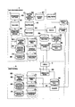
- FIG. 1 is a diagram showing a structure of an application generation system including a data processing device which functions as an application generation device;
- FIG. 2 is a block diagram of each structure of the application generation system
- FIG. 3 is a diagram showing a structure of software and data of the application generation system
- FIG. 4 is an explanatory diagram showing a schema of a processing content of the application generation system
- FIG. 5A is a diagram showing an example of table data indicating a state where an “inventory” sheet of the table data is focused;
- FIG. 5B is a diagram showing an example of the table data indicating a state where a “floor inventory” sheet of the table data is focused;
- FIG. 5C is a diagram showing an example of the table data indicating a state where an “area inventory” sheet of the table data is focused;
- FIG. 6 is a display example of an operation screen of an application generation module
- FIG. 7A is a diagram showing an example of a display content of a display unit of a handy terminal where an operation application is being executed, indicating the display content corresponding to an operation application definition of “inventory”;
- FIG. 7B is a diagram showing an example of a display content of the display unit of the handy terminal where the operation application is being executed, indicating a display content corresponding to an operation application definition of “floor inventory”;
- FIG. 7C is a diagram showing an example of a display content of the display unit of the handy terminal where the operation application is being executed, indicating a display content corresponding to an operation application definition of “area inventory”;
- FIG. 8A is a diagram showing an example of a focus position in a display screen when the operation application is being executed, indicating a state before data of inventory and person in charge are inputted and the display content being corresponded to the operation application definition of “inventory” shown in FIG. 7A ;
- FIG. 8B is a diagram showing an example of the focus position in the display screen when the operation application is executed, indicating a state after date of inventory and person in charge are inputted and the display content being corresponded to the operation application definition of “inventory” shown in FIG. 7A ;
- FIG. 9 is a diagram showing an example of a display content of a display device 38 of a handy terminal 5 where an operation menu is being executed;
- FIG. 10A is a diagram showing an example of a menu sheet, indicating a display example of the menu sheet which is generated as the last sheet of the table data;
- FIG. 10B is a diagram showing an example of the menu sheet, indicating a printed menu sheet
- FIG. 11A is a diagram showing a display example of a registration table data, indicating the registration table data before registration data is stored;
- FIG. 11B is a diagram showing a display example of the registration table data, indication the registration table data after the registration data is stored;
- FIG. 12 is a schematic diagram showing a relationship between an item which is defined in each cell of the table data and data which is set in each cell of the table data and items which are defined in the menu sheet and the registration table data;
- FIG. 13A is a diagram showing an example of a barcode, indicating the barcode of “BS 1 ”;
- FIG. 13B is a diagram showing an example of the barcode, indicating the barcode of “BE 1 ”;
- FIG. 14 is a diagram showing an example of a content of an operation menu definition
- FIG. 15A is a schematic diagram showing an example of a display content of a menu screen, indicating a display content of a main menu
- FIG. 15B is a schematic diagram showing an example of a display contents of the menu screen, indication a display content of a configuration menu
- FIG. 16 is a diagram showing an example of a content of an operation application definition
- FIG. 17A is a schematic diagram showing an example of a display content when the operation application is executed, indicating symbols of each of the parts;
- FIG. 17B is a schematic diagram showing an example of a display content when the operation application is executed, indicating positions which are shown by variables relating to layout;
- FIG. 18 shows an example of a display content of the operation application in a state where input is carried out to each textbox
- FIG. 19 shows an example of a content of registration data
- FIG. 20 is a schematic diagram showing an example of a content of registration table data after data of the registration data is stored
- FIG. 21 is a flowchart showing a content of an application generation process
- FIG. 22 is a flowchart showing a content of a generation process of the operation menu definition shown in step S 1 ;
- FIG. 23 is a flowchart showing a content of a main operation menu definition output process shown in step S 12 ;
- FIG. 24 is a flowchart showing a content of a configuration operation menu definition output process shown in step S 13 ;
- FIG. 25 is a flowchart showing a content of a generation process of all of application definitions shown in step S 2 ;
- FIG. 26 is a flowchart showing a content of an output process of each application definition shown in step S 42 ;
- FIG. 27 is a flowchart showing a content of a [CTRL_BASE] output process shown in step S 52 ;
- FIG. 28 is a flowchart showing a content of a [CTRL] output process shown in step S 53 :
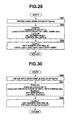
- FIG. 29 is a flowchart showing a content of a LABEL output process shown in step S 62 ;
- FIG. 30 is a flowchart showing a content of an EDIT output process shown in step S 63 ;
- FIG. 31 is a flowchart showing a content of a [FOCUS] output process shown in step S 54 ;
- FIG. 32 is a flowchart showing a content of a [SCAN] output process shown in step S 55 ;
- FIG. 33 is a flowchart showing a content of an [ENTRY] output process shown in step S 56 :
- FIG. 34 is a flowchart showing a content of a FIELDS output process shown in step S 123 ;
- FIG. 35 is a flowchart showing a content of a VALUES output process shown in step S 124 ;
- FIG. 36 is a flowchart showing a content of a generation process of the registration table data shown in step S 3 ;
- FIG. 37 is a flowchart showing a content of a sheet generation process of the registration table data shown in step S 155 ;
- FIG. 38 is a flowchart showing a content of a menu sheet generation process shown in step S 4 ;
- FIG. 39 is a flowchart showing a content of a main menu label generation process shown in step S 177 ;
- FIG. 40 is a sub-flowchart showing a content of a configuration menu label generation process shown in step S 179 ;
- FIG. 41 is a flowchart showing a content of a monitoring process of a cradle
- FIG. 42 is a flowchart showing a content of a storing process of the registration data shown in step S 242 ;
- FIG. 43 is a flowchart showing a content of a start-up process of the operation menu
- FIG. 44 is a flowchart showing a content of a main menu display process shown in step S 273 ;
- FIG. 45 is a flowchart showing a processing content when a setting button is operated.
- FIG. 46 is a flowchart showing a content of a configuration display process shown in step S 291 ;
- FIG. 47 is a flowchart showing a processing content when a return button is operated.
- FIG. 48 is a flowchart showing a processing content when a menu button in a main menu screen is operated
- FIG. 49 is a flowchart showing a processing content when number keys in the main menu screen are operated.
- FIG. 50 is a flowchart showing a content of a start-up process of the operation application
- FIG. 51 is a flowchart showing a processing content when a menu button in a configuration menu screen is operated
- FIG. 52 is a flowchart showing a processing content when number keys in the configuration menu screen are operated.
- FIG. 53 is a flowchart showing a content of a start-up process of a configuration application
- FIG. 54 is a flowchart showing a content of a scan process of the menu sheet
- FIG. 55 is a flowchart showing a processing content to be carried out at the time of start-up of the operation application
- FIG. 56 is a flowchart showing a content of an EDIT focus-in process
- FIG. 57 is a flowchart showing a content of an EDIT focus-out process
- FIG. 58 is a flowchart showing a content of a scan process when the operation application is executed
- FIG. 59 is a flowchart showing a processing content when the focus is moved.
- FIG. 60 is a flowchart showing a processing content when a registration button and a return key of the input device are operated
- FIG. 61 is a flowchart showing a content of a registration data storage process shown in step S 434 and step S 441 ;
- FIG. 62 is a flowchart showing a content of a clearing process of a textbox shown in step S 435 and step S 442 ;
- FIG. 63 shows an example of a display content of a display device when creating a barcode label
- FIG. 64 shows an example of print data of the generated barcode label.
- FIG. 1 is a diagram showing a structure of an application generation system 100 including a data processing device 1 which functions as an application generation device.
- the application generation system 100 comprises a data processing device 1 , a cradle 2 , a label printer 3 , a printer 4 and a handy terminal 5 .
- the data processing device 1 and each of other devices are connected via a cable 6 .
- the data processing device 1 is a computer having a function to generate an application which is to be executed by the handy terminal 5 , a function to transfer the generated application to the handy terminal, a function to take in and store data which is stored in the handy terminal 5 , a function to carry out a control of printing by the label printer 3 and the printer 4 and a function to control other various types of operations of the application generation system 1 .
- the cradle 2 is connected with the data processing device 1 via the cable 6 , and also, the cradle 2 includes a connection terminal to connect with a terminal of a communication device 36 (after mentioned) of the handy terminal 5 which is mounted on the cradle 2 . Further, the cradle 2 functions as an interface for connecting the handy terminal 5 and the data processing device 1 .
- the label printer 3 has a function to printout a label in which barcodes that can be read by the scanner 41 (after mentioned) of the handy terminal 5 are printed.
- the printer 4 has a function to carry out various types of printings including a printing of menu sheets for selecting application which is to be executed by the handy terminal 5 .
- the handy terminal 5 executes the application which is transferred from the data processing device 1 .
- the handy terminal 5 has a function to collect and store various types of data by reading the barcodes by the scanner 41 (after mentioned) and a function to store the data which is inputted by the input operation by the input device 37 (after mentioned).
- the definition of the data which is collected and stored by the handy terminal 5 is based on the application.
- FIG. 2 is a block diagram of each structure of the application generation system 100 .
- the data processing device 1 comprises CPU 11 , RAM 12 , ROM 13 , HDD 14 , a communication device 16 , an input device 17 , a display device 18 and an interface 19 (in the following description and diagrams, the interface 19 is indicated as I/F 19 ), and each of these compositions are connected by a bus 20 .
- the CPU 11 reads and carries out execution process of programs, data and the like according to processing content from the ROM 13 and the HDD 14 to carry out various types of processes related to operations of the data processing device 1 and the application generation system 100 .
- the programs and data which are read and the parameters and the like which are temporarily generated in the process carried out by the CPU 11 are stored in the RAM 12 .
- the ROM 13 stores various types of programs, data and the like which are read by the CPU 11 , the programs, data and the like being non-rewritable.
- the HDD 14 stores various types of programs, data and the like which are read by the CPU 11 so as to be rewritable, and also, the HDD 14 functions as a storage region to store various types of data generated as processing result of the CPU 11 , data taken in from the handy terminal 5 and the like.
- the communication device 16 has a function to carry out communication with other devices.
- the communication device 16 is a Network Interface Card (NIC) and a wireless LAN device for the Ethernet (registered trademark) connection, a device for communication by Bluetooth and the like, for example, and the devices can be used depending on the usages.
- NIC Network Interface Card
- wireless LAN device for the Ethernet (registered trademark) connection
- Bluetooth Bluetooth
- the devices can be used depending on the usages.
- the input device 17 carries out input from outside relating to various types of processing contents which are carried out by the data processing device 1 .
- the input device 17 is a key board, a mouse and the like, for example, and human interfaces other than a key board, a mouse and the like can also be used.
- the display device 18 displays content of screen output which is carried out by the data processing device 1 .
- the display device 18 is a liquid crystal display, a cathode-ray display, an organic Electro Luminescence display or the like, for example, and screen display devices other than the above can also be used.
- the I/F 19 is an interface to connect the data processing device 1 and other devices.
- the I/F 19 is USB (Universal Serial Bus), IEEE1394 or other serial port or parallel port and the like, for example, and can be used depending on the usages.
- the data processing device 1 , the cradle 2 , the label printer 3 and the printer 4 are connected via USB, and the cable 6 are USB cables.
- the handy terminal 5 comprises CPU 31 , RAM 32 , ROM 33 , a flash memory 34 , a communication device 36 , an input device 37 , a display device 38 , an interface 39 (in the following description and drawings, the interface 39 is indicated as I/F 39 ), a scanner 41 and a trigger 42 , and each of the compositions are connected by a bus 40 .
- the CPU 31 reads programs, data and the like according to the processing content from the ROM 33 and the flash memory 34 and carries out the execution process to carry out various types of processes regarding operation of the handy terminal 5 .
- the programs, data and the like which are read and parameters and the like which are temporarily generated in the process which is carried out by the CPU 31 are stored in the RAM 32 .
- the ROM 33 stores various types of programs, data and the like which are read by the CPU 31 , the programs, data and the like being non-rewritable.
- the flash memory 34 stores various types of programs, data and the like which are read by the CPU 31 so as to be rewriteable, and also, the flash memory 34 functions as a storage region to store various types of data which are generated as processing result of the CPU 31 and the application which are transmitted from the data processing device 1 and the like.
- the communication device 36 has a function to carry out communication with other devices.
- the communication device 36 is Network Interface Card (NIC) and a wireless LAN device for the Ethernet (registered trademark) connection, a device for communication by Bluetooth and the like, for example, and the devices can be used depending on the usages.
- the communication device 36 has a terminal for connecting with a connection terminal of the cradle 2 , and the communication device 36 is structured so as to carry out communication with the communication device 16 of the data processing device 1 via the cradle 2 and the cable 6 .
- the input device 37 carries out input from outside regarding various types of processing contents which are carried out by the handy terminal 5 .
- the input device 37 is buttons, keys or the like which are provided integrally with the handy terminal 5 , for example, and other human interfaces such as an external key board can also be used.
- the display device 38 displays a screen output content of the handy terminal 5 .
- the display device 38 is a liquid crystal display, an organic Electro Luminescence display or the like, for example, and other screen display devices can also be used.
- the I/F 39 is an interface for connecting the handy terminal 5 with other devices.
- the I/F 39 is USB (Universal Serial Bus), IEEE1394 or other serial port or parallel port and the like, and can be used depending on the usages.
- the handy terminal 5 and the cradle 2 are connected via USB, and a USB port to connect with the data processing device 1 and a USB port to connect with the handy terminal 5 are individually provided at the cradle 2 as the interfaces 51 (I/F 51 ).
- the scanner 41 reads barcodes. Particularly, when the reading unit of the scanner 41 is held over a barcode while the scanner 41 is operating, the scanner 41 reads information indicated by the barcode. The information read by the scanner 41 is input to the CPU 31 as data.
- the trigger key 42 is a key to switch ON/OFF of operation of the scanner 41 .
- the scanner 41 is turned ON by the operation of the trigger key 42 , reading of barcodes by the scanner 41 can be carried out.
- FIG. 3 is a diagram showing a structure of software and data of the application generation system 100 .
- the data processing device 1 comprises various types of software such as a spreadsheet software 61 , an application generation module 62 , a communication module 63 , a table data registration module 64 and a barcode label generation module 65 , and they are stored in the HDD 14 . Further, an operation menu 71 , an operation application 72 , a configuration application 73 , a configuration definition 74 and master data 75 are stored in the HDD 14 .
- the handy terminal comprises a communication module 66 .
- the communication module 66 is stored in the flash memory 34 .
- the spreadsheet software 61 is software which can generate table data 81 in a table format having lines and columns.
- a user who operates the data processing device 1 can define an arbitrary item in each column of the table data 81 by carrying out input operation with regards to the input device 17 .
- the application generation module 62 is a program to generate an operation menu definition 82 , operation application definitions 83 , a menu sheet 84 and registration table data 85 based on the table data 81 .
- the operation menu definition 82 is data corresponding to the display content of the operation menu 71
- the operation application definitions 83 are data corresponding to the items in the operation application 72
- the menu sheet 84 is data of a sheet which is used to select the operation application which is to be executed by the handy terminal 5
- the registration table data 85 is data for storing the data which is collected and recorded by the handy terminal 5 .
- the communication module 63 is a program to carry out communication and transferring process between the data processing device 1 and the handy terminal 5 which are carried out via the cradle 2 in cooperation with the communication module 66 .
- the data processing device 1 transfers the application set 80 which includes the operation menu 71 , the operation application 72 , the configuration application 73 , the configuration definition 74 , the operation menu definition 82 and the operation application definition 83 to the handy terminal 5 .
- the handy terminal 5 executes the operation application 72 to transfer the registration data 86 which is the data collected and stored via the scanner 41 or the input device 37 to the data processing device 1 .
- the transferring between the communication modules 63 and 66 is carried out by the connection via the cradle 2 .
- the transferring may be carried out via the communication between the communication devices 16 and 36 .
- the table data registration module 64 is a program to store data in the registration table data 85 based on the registration data 86 .
- the operation of the table data registration module 64 will be after-mentioned in detail.
- the barcode label creating module 65 is a program to generate the barcode sheet 87 based on the master data 75 .
- FIG. 4 is an explanatory diagram showing a schema of a processing content of the application generation system 100 .
- the table data 81 is generated by using the spreadsheet software 61 of the data processing device 1 , and arbitrary items are defined in the table data 81 . Thereafter, the operation menu definition 82 , the operation application definition 83 , the menu sheet 84 and the registration table data 85 are generated from the table data 81 by using the application generation module 62 .
- the operation application definition 83 the handy terminal 5 executes the operation application 72 to decide items of data which are to be collected.
- the content of the operation application definition 83 corresponds to the items defined in the table data 81 .
- the data processing device 1 transfers the application set 80 including the operation menu definition 82 and the operation application definition 83 to the handy terminal 5 .
- the handy terminal 5 collects data by executing the operation application 72 . Selecting of the operation application to be executed can be carried out by selecting from the operation menu 71 , and alternatively can be carried out by using the menu sheet 84 .
- the display items of the operation menu 71 are decided by the operation menu definition 82 . Further, by the configuration application 73 , various types of settings of the handy terminal 5 can be changed and confirmed.
- the data which is collected and stored by using the handy terminal 5 is stored in the flash memory 34 of the handy terminal 5 as the registration data 86 .
- the registration data 86 is transferred to the data processing device 1 from the handy terminal 5 .
- the data processing device 1 stores data based on the registration data 86 in the registration table data 85 by the table data registration module 64 .
- the data collection is carried out as described above.
- FIGS. 5A to 5C are diagrams showing examples of the table data 81 .
- FIG. 5A shows a state where focus is on the “inventory” sheet of the table data 81 .
- FIG. 5B shows a state where focus is on the “floor inventory” sheet of the table data 81 .
- FIG. 5C shows a state where focus is on the “area inventory” sheet of the table data 81 .
- alignment in vertical direction in the table data 81 is called lines, and alignment in side direction in the table data 81 is called columns.
- the table data 81 is data in tabular format which can define one or a plurality of sheets. In the first line of each column of each of the sheets, an item is defined. The content of the items and the number of the items are set by a user's discretion.
- items corresponding to information to be read by the scanner 41 of the handy terminal 5 scanning the barcodes can be assigned.
- a user can make an arbitrary item be displayed in bold font (setting an attribution of bold font assignment) in comparison to other items to assign the item as the item corresponding to the information to be read by the scanner 41 .
- the item which corresponds to the information to be read by the scanner 41 can also be assigned by other assigning methods. For example, a method of changing font color, a method of attributing a specific identifier to the item and the like.
- the item corresponding to the information to be read by the scanner 41 can be discriminated from other items in visual way, such as by using the method of changing the font to a bold font or the like as in the embodiment.
- the CPU 11 assumes that the item in the most left of each sheet is the item corresponding to the information to be read by the scanner 41 and carries out processing to the item in the most left of each sheet.
- FIG. 6 is a display example of an operation screen of the application generation module 62 .
- the application generation module 62 comprises an application generation button 91 .
- the application generation button 91 By clicking the application generation button 91 , the operation menu definition 82 , the operation application definition 83 , the menu sheet 84 and the registration table data 85 according to the content of each sheet of the table data 81 are generated.
- the application generation module 62 is activated by operating the application generation button 91 which is provided at the first sheet of the data file in tabular format including the table data 81 .
- a sheet which becomes the table data 81 can be additionally created and items can be defined in the data file in tabular format including the sheet having the application generation button 91 .
- the table data 81 , the application generation module 62 and the interface for activating the application generation module 62 may be individual files, and method is not limited to the method shown in the embodiment.
- FIGS. 7A to 7C are diagrams showing examples of display contents of the display device 38 of the handy terminal 5 where the operation application 72 is being executed.
- FIG. 7A shows a display content corresponding to the operation application definition 83 of “inventory”.
- FIG. 7B shows a display content corresponding to the operation application definition 83 of “floor inventory”.
- FIG. 7C shows a display content corresponding to the operation application definition 83 of “area inventory”.
- the items which are displayed in the screen display of the operation application 72 and which can be collected as data correspond to the content of the operation application definition 83 . Further, the content of the operation application definition 83 corresponds to the items defined in the table data 81 . That is, the data which can be collected by executing the operation application 72 corresponds to the items defined in the table data 81 .
- the operation application definition 83 is generated individually for each of the sheets in which items are defined in the table data 81 . That is, when there is one sheet in which items are defined in the table data 81 , one operation application definition 83 is generated, and when there are plurality of sheets, a plurality of operation application definitions 83 are generated. In the embodiment, an example based on three sheets of “inventory”, “floor inventory” and “area inventory” is described.
- the display content corresponding to the operation application definition 83 of “inventory” shown in FIG. 7A corresponds to each of the items defined in the “inventory” sheet shown in FIG. 5A .
- the display content corresponding to the operation application definition 83 of “floor inventory” shown in FIG. 7B corresponds to each of the items defined in the “floor inventory” sheet shown in FIG. 5B .
- the display content corresponding to the operation application definition 83 of “area inventory” shown in FIG. 7C corresponds to each of the items defined in the “area inventory” sheets shown in FIG. 5C .
- the operation application 72 is one execute file, and by changing the operation application definition 83 to be read at the time of execution, each of the display contents and the contents of data collecting items shown in FIGS. 7A to 7C can be switched. That is, the operation application definition 83 functions as a definition file to define operation content of the operation application 72 , and the combination of the operation application 72 and the operation application definition 83 functions as an application program.
- FIGS. 8A and 8B are diagrams showing examples of focused position in the display screen where the operation application 72 is being executed.
- FIG. 8A shows an example before the date of inventory and the person in-charge are inputted.
- FIG. 8B shows an example after the date of inventory and the person in-charge are inputted.
- FIGS. 8A and 8B are display contents corresponding to the operation application definition 83 of “inventory” shown in FIG. 7A .
- the operation application 72 when the operation application 72 is executed, when the item corresponding to data to be collected based on barcode, among a plurality of items defined in the table data 81 , is not the first to be inputted and when the focus is to be moved by operating the “enter” button which is included in the display content or the return key which is comprised in the input device 38 after the input of the item to be inputted before the item corresponding to data to be collected based on barcode is finished, the CPU 31 makes the focus move to an item corresponding to data to be collected based on the barcode.
- FIG. 9 is a diagram showing an example of display content of the display device 38 of the handy terminal 5 where the operation menu 71 is being executed.
- the display content of the operation menu 71 corresponds to the content of the operation menu definition 82 . That is, the operation menu definition 82 functions as a definition file to define operation content of the operation menu 71 , and the combination of the operation menu 71 and the operation menu definition 82 functions as an application program.
- the operation menu 71 shown in FIG. 9 comprises menu buttons of “1. inventory”, “2. floor inventory” and “3. area inventory”. Each of the menu buttons corresponds to the content which is set when the operation application 72 is executed shown in FIGS. 7A to 7C , respectively. That is, the content of the operation menu definition 82 which decides the display content of the operation menu 71 correspond to the contents of the operation application definition 83 , that is, the content of the table data 81 .
- the application generation module 62 generates the operation application definitions 83 which correspond to each sheet of the table data 81 , and also, generates the operation menu definitions 81 which correspond to the content of the operation application definitions 83 .
- the operation menu 71 comprises an end button and a set button other than the menu buttons corresponding to the operation application definitions 83 .
- the end button is operated, the CPU 31 finishes the display of the operation menu 71 .
- the set button is operated, the CPU 31 executes the configuration application 73 .
- FIGS. 10A and 10B are diagrams showing examples of the menu sheet 84 .
- FIG. 10A shows a display example of a menu sheets 84 which is generated as a last sheet of the table data 81 .
- FIG. 10B shows an example of a menu sheet which is printed.
- the application generation module 62 generates the menu sheet 84 .
- the menu sheet includes [main menu] item and [configuration] item.
- the [main menu] item includes item names corresponding to each of the sheets which are generated in the table data 81 and barcodes formed in right side of each of the item names.
- the barcodes formed in the right side of each of the item names are printed on a print medium such as paper as shown in FIG. 10B , and when a barcode is read by the scanner 41 of the handy terminal 5 , the CPU 31 of the handy terminal 5 reads the operation application definition 83 which corresponds to the item name described in the left side of the barcode to execute the operation application 71 . That is, by reading the printed menu sheet by the handy terminal 5 , the data collecting item of the operation application 71 to be executed can be selected.
- the [configuration] item includes item names related to configuration of the handy terminal and barcodes formed in the right side of each of the item names, and by reading a barcode by the scanner 41 , the configuration application 73 in which the configuration definition 74 corresponding to the item name of the configuration is read can be executed.
- the configuration definition 74 which is read by the configuration application 73 is one
- the item name of the [configuration] item shown in FIGS. 10A and 10B corresponds to the one configuration definition 74 .
- Sheet name of the generated menu sheet 84 is “!menu sheet”, and “!” (exclamation mark) is indicated as the first letter of the sheet name.
- FIGS. 11A and 11B are diagrams showing display examples of the registration table data 85 .
- FIG. 11A shows a display example of the registration table data 85 before the registration data 86 is stored.
- FIG. 11B shows a display example of the registration table data 85 after the registration data 86 is stored.
- the registration table data 85 has sheets corresponding to each of the sheets of the generated table data 81 . Further, as shown in FIG. 11A , the items which are defined in each column of the first line of the table data 81 are set in each column of the first line of each of the sheets of the registration table data 85 just after being generated by the application generation module 62 , and data is not entered in the second line. In other wards, the registration table data 85 is generated in tabular form data in which data of the second line in the table data 81 is deleted.
- the table data registration module 64 stores data in the registration table data 85 based on the registration data 86 , the registration data 86 which is collected and stored by using the handy terminal 5 is recorded in the second line and in the lines thereafter of the registration table data 85 as shown in FIG. 11B .
- the operation application definitions 83 read by the operation application 72 which is executed by the handy terminal 5 the registration data 86 which is collected and stored by executing the operation application 72 in which the operation application definition 83 is read and the sheets of the registration table data 85 in which the registration data 86 is stored correspond to one another, respectively. That is, the registration data 86 and each sheet of the registration table data 85 are being managed by each operation application definition 83 , that is, sheet by sheet in the table data 81 .
- FIG. 12 is a schematic diagram showing a relationship between the items to be defined and the data to be set in each cell of the table data 81 and the items to be defined in the menu sheet 84 and in the registration table data 85 .
- each or the sheets of the table data 81 and the registration table data 85 are described as a sheet S 1 , a sheet S 2 . . . a sheet S 1 .
- the item S 1 F 1 is defined in the first line of first column in the sheet S 1 .
- the item S 1 F 2 is defined in the first line of the second column in the sheet S 1
- the item S 1 Fn 1 is defined in the first line of the n 1 column in the sheet S 1 .
- the item S 2 F 1 is defined in the first line of the first column in the sheet S 2 . That is, the item SiFni is defined in the first line of the ni column in the sheet Si.
- the data S 1 P 1 is set in the second line of the first column in the sheet S 1 .
- the data S 1 P 2 is set in the second line of the second column in the sheet S 1
- the data S 1 Pn 2 is set in the second line of the n 1 column in the sheet S 1 .
- the data S 2 P 1 is set in the second line of the first column in the sheet S 2 . That is, the data SiPni is set in the second line of the ni column in the sheet Si.
- the item “output book name” is defined in the first line of the first column in the first sheet of the tabular form data file including each sheet of the table data 81 , and “DATA.XLS” is set in the first line of the second column which is in the right side of the item “output book name”.
- the item “output book name” is the item name for assigning file name of the registration table data 85
- “DATA. XLS” set in the right side of the item “output book name” becomes the file name of the registration table data 85 in the example shown in FIG. 12 .
- the item “referring book name” is defined in the second line of the first column and the item “barcode book name” is defined in the third line of the first column in the first sheet of the tabular form data file including each sheet of table data 81 .
- “MT. XLS” is set in the second line of the second column in the right side of the item “referring book name” and “BC.XLS” is set in the third line of the second column in the right side of the item “barcode book name”.
- the item “referring book name” is the file name of the master data 75
- the “MT.XLS” which is set in the right side of the item “referring book name” becomes the file name of the master data 75 in the example shown in FIG. 12 .
- the item “barcode book name” is the file name of the barcode sheet 87 , and the “BC.XLS” which is set in the right side of the item “barcode book name” becomes the file name of the barcode sheet 87 in the example shown in FIG. 12 .
- each sheet of the registration table data 85 is generated as tabular form data in which the second line of each sheet in the table data 81 is empty.
- the menu sheet 84 is created as the last sheet of the tabular form data file including the table data 81 , and the sheet name is “! menu sheet”.
- the letter string of “menu sheet” is set in the first line and “main menu” is set in the third line. Further, in the forth line of the second column of the menu sheet 84 , the letter string corresponding to “1.S 1 ” is set.
- the letter string corresponding to “1.S 1 ” is a letter string in which the letter string of sheet name of the sheet S 1 of the table data 81 and “1.” indicating the number being the first are combined. For example, in a case where the sheet name of the sheet S 1 is “inventory”, the letter string of “1.inventory” will be set in the forth line of the second column in the menu sheet 84 .
- a letter string corresponding to “2.S 2 ” is set in the fifth line of the second column in the menu sheet 84
- a letter string corresponding to “i.Si” which corresponds to each of the sheets of the table data 81 is set in each of the lines after the fifth line to the i+3 line.
- the letter string of [configuration] is set in the i+5 line of the second column in the menu sheet 84 . Then, the letter string corresponding to “1.E 1 ” is set in the i+6(i+1+5) line of the second column in the menu sheet 84 .
- the letter string corresponding to “1.E 1 ” is a letter string omitting the extension from the file name of the configuration definition 74 and in which a number is attached at the beginning. For example, when the neme of the first configuration is “terminal information. INI”, the letter sting of “1.
- terminal information is set in the i+6 line of the second column in the menu sheet 84 , the letter sting being a combination of the letter string of “terminal information” and “1.” indicating the number being the first.
- a letter string corresponding to “2.E 2 ” is set in the i+7(i+2+5) line of the second column in the menu sheet 84
- letter strings corresponding to “j.Ej” corresponding to each sheet of the table data 81 are set in the rows thereafter to the i+j+5 line, respectively.
- the name of each configuration corresponds to each of the individual configuration definition 74 , respectively.
- FIG. 13 is a diagram showing an example of a barcode.
- FIG. 13A shows an example of the barcode “BS 1 ”
- FIG. 13B shows an example of the barcode “BE 1 ”.
- the barcodes which are to be set in the fifth column in the menu sheet 84 are the barcodes generated according to a number and the barcode pattern which are predetermined, and each of them is set as a barcode corresponding to the item in the left side of each of the barcodes.
- each sheet name of the table data 81 corresponds to the operation application definitions 83 which are to be generated. That is, when the menu sheet 84 is printed and when any one of the barcodes of “BS 1 ”, “BS 2 ” . . . “BSi” is read by the scanner 41 of the handy terminal 5 , the operation application 72 in which the operation application definition 83 corresponding to the barcode is read can be executed. Similarly, when any one of the barcodes of “BE 1 ”, BE 2 ” . . . “BEj” is read, the configuration application 73 in which the configuration 74 is read can be executed.
- the barcodes of “BSi” and “BEj” are generated as barcodes showing numbers of four digits. Further, as shown in FIG. 13A , the barcodes of “BSi” are barcodes having consecutive numbers starting from the barcode of “BS 1 ” indicating the number of 0001, and as shown in FIG. 13B , the barcodes of “BEj” are barcodes having consecutive numbers starting from the barcode of “BE 1 ” indicating the number of 9001.
- FIG. 14 is a diagram showing an example of a content of the operation menu definition 82 .
- the operation menu definition 82 comprises setting relating to [main menu] and setting relating to [configuration].
- the setting relating to [main menu] is described in a form of “i.Si,Si.INI,0000+i”.
- i is a value of net increase in which 1 is the initial value and functions as menu number of the main menu.
- Si is a sheet name corresponding to the table data 81 and “Si.INI” is a file name of the operation application definition 83 corresponding to the sheet name which is indicated by “Si”. Further, “0000+i” is a number (scancode number) for verifying to the scancode and is expressed by a numerical value in which i is added to the four digit number of initial value 0, and further, becomes the same value as the number of barcode BSi corresponding to the item name of the operation application definition 83 which is indicated by Si.INI in the menu sheet 84 .
- the setting related to [main menu] are provided according to the number of the operation application definitions 83 , that is, according to the number of sheets S 1 to Si which are generated by the table data 81 , and the settings are orderly described.
- FIGS. 15A and 15B are schematic diagrams showing examples of a display content of the menu screen 71 .
- FIG. 15A shows a display content of the main menu.
- FIG. 15B shows a display content of the configuration menu.
- the main menu and the configuration menu are displayed by the display device 38 of the handy terminal 5 .
- the main menu screen comprises menu buttons of “1.S 1 ”, “2.S 2 ” . . . “i.Si”, an end button and a set button.
- the menu buttons in the main menu screen are assigned so as to be BTN_S 1 , BTN_S 2 , . . . BTN_Si by the CPU 31 and the display name of each of the menu buttons is individually controlled.
- the configuration menu shown in FIG. 15B is displayed.
- the configuration menu comprises menu buttons of “1.E 1 ”, “2.E 2 ” . . . “j.Ej” and a return button.
- the menu buttons in the configuration menu are assigned so as to be BTN_E 1 , BTN_E 2 . . . BTN_Ej by the CPU 31 , and the display name of each of the menu buttons is individually controlled.
- the display content of the display device 38 returns to the main menu shown in FIG. 15A .
- FIG. 16 is a diagram showing an example of a content of the operation application definition 83 .
- FIGS. 17A and 17B are schematic diagrams showing examples of display content where the operation application 72 is being executed.
- FIG. 17A shows symbols of each part.
- FIG. 17B shows positions which are indicated by variables relating to layout.
- the operation application definition 83 includes a display content of title and each button of the display screen, a content relating to items and textboxes, a content relating to focus of the textboxes, a content relating to focus of the textboxes, a content relating to information to be read by the scanner 41 and a content relating to the file name of the registration data 86 , the file name which becomes the target when storing the data recorded in the registration data 86 in the registration table data 85 , and information showing the textbox corresponding to the sheet name, the item name and data source.
- the display contents of the title and each button of the display screen are included as data of [CTRL_BASE]
- a content relating to the item and the textboxes are included as data of [CTRL]
- a content relating to focus of the textboxes is included as data of [FOCUS]
- a content relating to information to be read by the scanner 41 is included as data of [SCAN]
- (numerical value) indicates a value of net increase in which 1 is initial value
- (variable name) indicates a content corresponding to a symbol attached to each display content shown in FIG. 17
- (type) indicates the type of the display content
- (starting position in X-direction) indicates the starting position in Y-direction)
- (width) and (height) indicate the layout of the display content
- (applied letter string) indicates the content of the letter string which is actually reflected in the display content.
- An initial value are respectively set to the variables ax, ay, aw, ah, bw, bh, lx, ly, lh, ex, ey, eh, sh and Glen used in the following formulas (1) to (20).
- the CPU 31 of the handy terminal 5 decides layout of each of the display contents based on the above initial values, the coordinate positions which are shown by each numerical value when displaying in the display device 38 and the formulas (1) to (20).
- T 1 x ax (1)
- T 1 y ay (2)
- T 1 w aw (3)
- T 1 h 20 (4)
- B 1 x ax (5)
- B 1 y ay+ah ⁇ bh (6)
- B 1 w bw (7)
- B 1 h bh (8)
- B 2 x ax+aw ⁇ bw (9)
- B 2 y ay+ah ⁇ bh (10)
- B 2 w bw (11)
- B 2 h bh (12)
- Lnix lx (13)
- Lniy ly +( lh+sh ) ⁇ ( ni ⁇ 1) (14)
- Lniw (byte count of letter string of SiFni ) ⁇ clen (15)
- Lnih 1 h
- the (byte count of letter string SiFni) of the formula (15) corresponds to the byte count of the letter string of the item SiFni which is defined in the table data 81
- the (byte count of letter string SiPni) of the formula (19) corresponds to the byte count of the letter string of the data SiPni which is set in the table data 81 .
- Each line of [FOCUS] respectively indicates the moving order of focus, the textbox which is focused at the time when the operation application 72 is activated and the textbox which is focused after the data is registered.
- FIG. 16 shows the moving order of focus, and here, the moving of focus is carried out in the order of EDIT 1 , EDIT 2 , . . . , EDITni.
- Each line of [SCAN] respectively shows whether information read by the scanner 41 can be used to be inputted in the textboxes of EDIT 1 , EDIT 2 , . . . , EDITni or not.
- ni which is at the beginning of each linw of [SCAN] is a number which means the setting of EDITni is indicated.
- ALL indicates that input of the information read by the scanner 41 is allowed
- NON indicates that input by the scanner 41 is not allowed.
- switch ON of the scanner 41 by operating the trigger 42 can be carried out and the information read by the scanner 41 can be inputted in the textbox.
- the decision of ALL or NON is based on whether the item corresponding to the textbox is assigned as the item corresponding to the information to be read when scanning, in the table data 81 which is the source, or not.
- Each row of [ENTRY] includes information indicating the file name of the registration data 86 , the file name, the sheet name and the item name which become the target when storing the data recorded in the registration data 86 in the registration table data 85 , and the textbox corresponding to the data source.
- FILENAME indicates the file name of the registration data 86 .
- CONNECT indicates the file name of the registration table data 85 .
- TABLE indicates the sheet name of the registration table data 85 which is assigned by CONNECT in which the content of the registration data 86 assigned in FILENAME is stored.
- FIELDS indicates the item of data to be read from the registration data 86 assigned in FILENAME to be stored, among the items defined in the sheet assigned in TABLE.
- VALUES indicates the textbox in which the data corresponding to the item assigned in FIELDS is to be inputted, and the description order corresponds to the order of the items described in FIELDS.
- the CPU 31 ends the operation application 72 .
- FIG. 18 shows an example of a display content of the operation application 72 in a state where input is carried out to each of the textboxes.
- FIG. 19 shows an example of a content of the registration data 86 .
- the CPU 31 records and stores the input content of each textbox in the registration data 86 as shown in FIG. 19 .
- the registration data 86 includes an entry to assign the file name and the sheet name of the registration table data 85 which is to be stored, an entry to assign the items of data to be stored in the registration table data 85 and an entry showing the content of data to be stored in the registration table data 85 .
- the first line of the registration data 86 shown in FIG. 19 is the entry to assign the file name and the sheet name of the registration table data 85 to be stored, and the content of the first line is same as the assigned content of CONNECT and the assigned content of TABLE of the operation application definition 83 read by the operation application 72 which is the source of input of the registration data 86 .
- the second line of the registration data 86 shown in FIG. 19 is the entry to assign the items of data to be stored in the registration table data 85 , and the content of the second line is same as the content of FIELDS of the operation application definition 83 read by the operation application 72 which is the source of input of the registration data 86 .
- the lines after the third line of the registration data 86 shown in FIG. 19 are the entries showing contents of data to be stored in the registration table data 85 , and the contents of the lines after the third line correspond to each data which was inputted to the textboxes assigned in VALUES of the operation application definition 83 read by the operation application 72 , which is the source of input of the registration data 86 , in the display screen while the operation application 72 is being executed.
- the last line of the registration data 86 corresponds to the input contents of each of the textboxes shown in FIG. 18 .
- the entry indicating the content of data to be stored in the registration table data 85 is sequentially and additionally recorded and stored in the lines after the third line of the registration data 86 .
- FIG. 20 is a schematic diagram showing an example of a content of the registration table data 85 after the data of registration data 86 is stored.
- each sheet of the registration table data 85 is generated in a state where the second line of each sheet of the table data 81 which is the source is empty. Thereafter, when the CPU 11 of the data processing device 1 executes the table data registration module 64 to store the data in the registration table data 85 based on the registration data 86 , the content of the registration data 86 is reflected in the registration table data 85 as shown in FIG. 20 .
- the entries indicating the content of data to be stored in the registration table data 85 which is recorded and stored in the lines after the third line in the registration data 86 are sequentially stored in the lines after the second line in the registration table data 85 .
- the registration data 86 stored in the registration table data 85 is deleted. Thereafter, when data is to be stored in the registration table data 85 based on the registration data 86 which is newly recorded and stored, the CPU 11 stores the entries which indicate the content of data to be stored in the registration table data 85 included in the registration data 86 in the first empty line which exits after the second line in the registration table data 85 and the lines thereafter.
- FIG. 21 is a flowchart showing a content of the application generation process.
- the CPU 11 orderly carries out a generation process of the operation menu definition 82 (step S 1 ), a generation process of all of the operation application definition 83 (step S 2 ), a generation process of the registration table data 85 (step S 3 ) and a generation process of the menu sheet (step S 4 ). Thereafter, the CPU 11 generates a shortcut of the table data registration module 64 (step S 5 ), registers the shortcut generated in step S 5 in the startup (step S 6 ), and activates the table data registration module 64 (step S 7 ).
- FIG. 22 is a flowchart showing the content of the generation process of the operation menu definition 82 shown in step S 1 of FIG. 21 .
- the CPU 11 generates an empty file which is generated as the operation menu definition 82 and opens the file (step S 11 ), and orderly carries out a main operation menu definition output process (step S 12 ) and a configuration operation menu definition output process (step S 13 ). Thereafter, the CPU 11 closes the file of the operation menu definition 82 (step S 14 ).
- FIG. 23 is a flowchart showing the content of the main operation menu definition output process shown in step S 12 of FIG. 22 .
- the CPU 11 outputs the letter string of [main menu] which is the main menu section name (step S 21 ). Then, the CPU 11 declares the counter q by the initial value 1, and carries out the process of repeating the following step S 23 and step S 24 to the number of sheets (i of sheet Si) which are created in the table data 81 (step S 22 ).
- FIG. 24 is a flowchart showing the content of the configuration operation menu definition output process shown in step S 13 of FIG. 22 .
- the CPU 11 outputs the letter string of [configuration] which is the configuration section name (step S 31 ). Then, the CPU 11 declares the counter r by the initial value 1, and carries out the process of repeating the following step S 33 and step S 34 to the number of files (j) of the configuration definition 74 (step S 32 ).
- FIG. 25 is a flowchart indicating the content of the generation process of all of the operation application definitions 83 shown in step S 2 of FIG. 21 .
- the CPU 11 declares the counter q by the initial value 1, and carries out a process of repeating the output process (step S 42 ) of each of the operation application definitions 83 to the number of the sheets (i of sheet Si) created in the table data 81 (step S 41 ).
- FIG. 26 is a flowchart showing the content of the output process of each of the operation application definitions 83 shown in step S 42 of FIG. 25 .
- the CPU 11 generates an empty file which is generated as Sq.INI and opens the file (step S 51 ), and orderly carries out [CTRL_BASE] output process (step S 52 ), [CTRL] output process (step S 53 ), [FOCUS] output process (step S 54 ), [SCAN] output process (step S 55 ) and [ENTRY] output process (step S 56 ).
- FIG. 27 is a flowchart showing the content of [CTRL_BASE] output process shown in step S 52 of FIG. 26 .
- FIG. 28 is a flowchart showing the content of [CTRL] output process shown in step S 53 of FIG. 26 .
- the CPU 11 outputs the section name of [CTRL_BASE] (step S 71 ). Then, the CPU 11 declares the counter m by the initial value 1, and carries out a process of repeating the LABEL output process (step S 73 ) and the EDIT output process (step S 74 ) to the number of items defined in the sheet Sq, that is, the value of nq in the last item SqFnq (step S 72 ).
- FIG. 29 is a flowchart showing the content of the LABEL output process shown in step S 73 of FIG. 28 .
- the CPU 11 obtains the value (letter string) of item SqFm which is defined as the LABEL name (step S 81 ). Then, the CPU 11 calculates Lqmx, Lqmy, Lqmw and Lqmh based on the formulas (13) to (16), and also, declares variables corresponding to the key number and the control ID and sets the value of each variable by executing the following formulas (21) and (22) (step S 82 ).
- LABELm is a letter string in which the value of counter m is added to the end of the letter string LABEL.
- Key number m ⁇ 2 ⁇ 1 (21)
- Control ID LABEL m (22)
- FIG. 30 is a flowchart showing the content of the EDIT output process shown in step S 74 of FIG. 28 .
- the CPU 11 obtains the value (letter string) of the item SqPm which is defined as an input data sample for calculating the letter string byte count (step S 86 ). Then, the CPU 11 calculates Eqmx, Eqmy, Eqmw and Eqmh based on the formulas (17) to (20), and also, declares variables corresponding to the key number and the control ID and sets the value of each variable by executing the following formulas (23) and (24) (step S 87 ).
- FIG. 31 is a flowchart showing the content of [FOCUS] output shown in step S 54 of FIG. 26 .
- the CPU 11 determines whether attribute is set to the items SqF 1 to SqFnq which are defined so as to assign the items as items corresponding to the information to be read when scanning is carried out (step S 94 ).
- step S 94 when the attribution is set to any one of the items (step S 94 : YES), the CPU 11 declares the counter m by the initial value 1, and carries out a process of repeating the following step S 97 to the number of items which are defined in the sheet Sq, that is, the value of nq of the last item SqFnq (step S 96 ).
- step S 97 determines whether the attribution is set to the item SqFm (step S 97 ).
- step S 97 when the attribution is not set (step S 97 : NO), the process returns to step S 96 .
- FIG. 32 is a flowchart showing the content of [SCAN] output process shown in step S 55 of FIG. 26 .
- the CPU 11 outputs the section name of [SCAN] (step S 101 ). Then, the CPU 11 determines whether the attribution is set to the items SqF 1 to SqFnq which are defined so as to assign the items as items corresponding to the information to be read when scanning is carried out or not (step S 102 ).
- step S 102 when the attribution is set to any one of the items (step S 102 : YES), the CPU 11 declares the counter m by the initial value 1, and carries out a process of repeating the following step S 104 to step S 108 to the number of items defined in the sheet Sq, that is, the value of nq of the last item SqFnq (step S 103 ).
- the CPU 11 determines whether the attribution is set to the item SqFm or not (step S 105 ).
- the CPU 11 determines whether the attribution is set to the item SqFm or not (step S 105 ).
- the CPU 11 outputs ALL for the scan type (step S 106 ), and when the attribution is not set (step S 105 : NO), the CPU 11 outputs NON for the scan type (step S 107 ).
- step S 106 or step S 107 the CPU 11 carries out an output based on the result obtained in step S 106 or step S 107 as scan information of EDITm (step S 108 ).
- step S 102 when the attribution is not set to any of the items (step S 102 : NO), the CPU 11 declares the counter m by the initial value 1 (step S 109 ).
- FIG. 33 is a flowchart showing the content of [ENTRY] output process shown in step S 56 of FIG. 26 .
- the CPU 11 orderly carries out output of the section name of [ENTRY] (step S 121 ) and a registration attribution output (step S 122 ).
- FIG. 34 is a flowchart showing the content of the FIELDS output process shown in step S 123 of FIG. 33 .
- FIG. 35 is a flowchart showing the content of VALUES output process shown in step S 124 of FIG. 33 .
- FIG. 36 is a flowchart showing the content of a generation process of the registration table data 85 shown in step S 3 of FIG. 21 .
- the CPU 11 obtains the file name which is set as the item “output book name” (step S 151 ).
- the CPU 11 confirms whether the registration table data 85 of the file name which is obtained in step S 151 exists in the HDD 14 or not (step S 152 ).
- the CPU 11 generates a registration table data 85 in the file name obtained in step S 151 (step S 153 ).
- step S 153 After the process of step S 153 or when the file exists in step S 152 (step S 152 : YES), the CPU 11 opens the registration table data 85 (step S 154 ), carries out the sheet generation process of the registration table data 85 (step S 155 ), and closes the registration table data 85 (step S 156 ).
- FIG. 37 is a flowchart showing the content of the sheet generation process of the registration table data 85 shown in step S 155 of FIG. 36 .
- the CPU 11 declares the counter q by the initial value 1, and carries out a process of repeating the following step S 162 to step S 166 to the number of sheets created in the table data 81 , that is, the value indicated by i of the sheets S 1 to Si (step S 161 ).
- the CPU 11 determines whether a sheet in which the sheet name is S 1 exists in the registration table data 85 or not (step S 162 ).
- the CPU 11 changes the name of the sheet named Sq which already exists to a different name (step S 163 ), and makes the display device 18 display a message to inform that the name of the sheet named Sq which already existed have been changed (step S 164 ).
- step S 164 copies the sheet Sq of the table data 81 to the registration table data 85 (step S 165 ) and clears the data except the first line of the sheet Sq of the copied registration table data 85 (step S 166 ).
- FIG. 38 is a flowchart showing the content of the menu sheet generation process shown in step S 4 of FIG. 21 .
- the CPU 11 orderly carries out a process to delete the existing menu sheet in the table data 81 (step S 171 ) and a process to create a new menu sheet in the table data 81 (step S 172 ).
- the CPU 11 carries out the attribution setting (for example, font, line height and the like) of the line in which the title is set in step S 174 (step S 175 ).
- the attribution setting for example, font, line height and the like
- the CPU 11 adds 1 to the line number (line) (step S 176 ) and carries out the main menu label generation process (step S 177 ).
- the CPU 11 adds 1 to the line number (line) after the main menu label generation process in step S 177 (step S 178 ) and carries out the configuration menu label generation process (step S 179 ).
- the CPU 11 sets the column width of the menu sheet (step S 180 ).
- various types of setting content such as the font and the line height in step S 175 and the column width in step S 180 are based on the setting content which is previously set.
- the setting content is included in the content of file which is assigned in the item “referring book name”, for example.
- step S 193 step S 200 , step S 213 and step S 220 .
- FIG. 39 is a flowchart showing the content of the main menu label generation process shown in step S 177 of FIG. 38 .
- the CPU 11 adds 1 to the line number (line) after the process of step S 176 (step S 191 ), and orderly carries out setting of the main menu name (step S 192 ) and a process of the attribution setting (for example, font, line height and the like) of the line in which the main menu name is set in step S 192 (step S 193 ).
- the CPU 11 declared the counter q by the initial value 1, and carries out a process of repeating the following step S 195 to step S 200 to the number of sheets created in the table data 81 , that is, the value indicated by i of the sheets S 1 to Si (step S 194 ).
- step S 197 q is the value of the counter and Sq is the sheet name of the q th sheet in the table data 81 .
- the CPU 11 carries out the attribution setting (for example, font, line height, ruled line and the like) for the line which is assigned in step S 195 (step S 200 ).
- the attribution setting for example, font, line height, ruled line and the like
- FIG. 40 is a flowchart showing the content of the configuration menu label generation process shown in step S 179 of FIG. 38 .
- the CPU 11 adds 1 to the line number (line) after processing of step S 178 (step S 211 ), and orderly carries out setting of the configuration menu name (step S 212 ) and a process of attribution setting (for example, font, line height and the like) of the line in which the configuration menu name is set in step S 212 (step S 213 ).
- the CPU 11 declares the counter r by the initial value 1, and carries out a process of repeating the following step S 215 to step S 220 to the value indicated by the number (j) of the configuration definition 74 (step S 214 ).
- the CPU 11 adds 1 to the line number (line) after the processing of step S 211 (step S 215 ) and obtains the calculation result of 90000+r as the barcode number (step S 216 ).
- r is a value of the counter and Er is the name of r th configuration.
- the CPU 11 carries out the attribution setting (for example, font, line height, ruled line and the like) of the line assigned in step S 215 (step S 220 ).
- the attribution setting for example, font, line height, ruled line and the like
- FIG. 41 is a flowchart showing the content of the monitoring process of the cradle 2 .
- the CPU 11 carries out a process of repeating the following step S 232 to step S 242 until the table data registration module 64 is finished (step S 231 ).
- the CPU 11 carries out the monitoring until the handy terminal 5 is connected via the cradle 2 (step S 232 : NO), and carries out the processes after step S 233 when the handy terminal 5 is connected (step S 232 : YES).
- the CPU 11 confirms whether each execution file of the application set 80 , that is, the operation menu 71 , the operation application 72 and the configuration application 73 are in the flash memory 34 of the handy terminal 5 or not (step S 233 ). When any one of the above execution files does not exist (step S 233 : NO), the CPU 11 transfers each execution file of the application set 80 to the handy terminal 5 (step S 234 ).
- step S 233 when there are all of the operation application 72 and the configuration application 73 in the flash memory 34 (step S 233 : YES), the CPU 11 confirms whether the updated data (file creation data or updated date) of each definition file, that is, the operation menu definition 82 , the operation application definition 83 and the configuration definition 74 of the application set 80 which is stored in the flash memory 34 is same as the file creation date or the updated data of each definition file of the application set 80 which is stored in the HDD 14 or not (step S 235 ).
- step S 235 NO
- the CPU 11 controls so as to make the CPU 31 of the handy terminal 5 finish all of the applications which are executed in the handy terminal 5 (step S 236 ).
- the CPU 11 transfers the operation menu definition 82 , the operation application definition 83 and the configuration definition 74 to the handy terminal 5 from the data processing device 1 (step S 237 ). Then, the CPU 11 makes the CPU 31 of the handy terminal 5 activate the operation menu 71 (step S 238 ).
- step S 238 After the processing of step S 238 or in step S 235 , when the file creation date or the updated date of the operation menu definition 82 , the operation application definition 83 and the configuration definition 74 is same as the file creation date or the updated data of each definition file of the application set 80 which is stored in the HDD 14 (step S 235 : YES), the CPU 11 confirms whether the registration data 86 is in the flash memory 5 or not (step S 239 ).
- step S 239 when the registration data 86 is in the flash memory 5 (step S 239 : YES), the CPU 11 obtains all of the registration data 86 (step S 240 ), deletes all of the registration data 86 in the flash memory 34 (step S 241 ), and carries out the storing process of the registration data 86 (step S 242 ).
- FIG. 42 is a flowchart showing the content of the storing process of the registration data 86 shown in step S 242 of FIG. 41 .
- the CPU 11 carries out a process of repeating the following step S 252 to step S 260 for number of times according to the number of all of the registration data which are obtained in step S 240 (step S 251 ).
- the CPU 11 opens the registration data 86 (step S 252 ), and orderly carries out a process to obtain the file name of the registration table data 85 which is to be the target for storing data (step S 253 ), a process to obtain the sheet name of the registration table data 85 which is to be the target for storing data (step S 254 ) and a process to obtain the field name of the registration table data 85 which is to be the target for storing data (step S 255 ).
- the field names of the registration table data 85 are the item names which are assigned in the second line of the registration data 86 shown in FIG. 19 . Thereafter, the registration table data 85 of the file name which is obtained in step S 253 is opened (step S 256 ).
- the CPU 11 carries out a process of repeating a process to add a record of the lines after the third line of the registration data 86 in the sheet having the sheet name which is obtained in step S 254 (step S 258 ) for a number of times according to the number of records (step S 257 ).
- the CPU 11 closes the registration table data 85 (step S 259 ) and closes the registration data 86 (step S 260 ).
- FIG. 43 is a flowchart showing the content of the activation process of the operation menu 71 .
- the CPU 31 of the handy terminal 5 reads the operation menu definition 71 (step S 271 ), makes the scanner 41 so as to be able to carry out the reading operation (step S 272 ), and carries out the main menu display process (step S 273 ).
- FIG. 44 is a flowchart showing the content of the main menu display process shown in step S 273 of FIG. 43 .
- the CPU 31 orderly carries out a process to obtain information relating to [main menu] from the operation menu definition 71 (step S 281 ), a process to set [main menu] for the title (step S 282 ) and a process to not display all of the buttons of the menu screen (step S 283 ).
- the CPU 31 sets the counter q by the initial value 1, and carries out a process of repeating the following step S 285 and step S 286 for the number of sheets created in the table data 81 , that is, the value indicated by i of the sheets S 1 to Si (step S 284 ).
- the CPU 31 caries out a process to set q. Sq for the button name of BTN_Sq (step S 285 ) and displays BTN_Sq (step S 286 ).
- q is the value of the counter and Sq is the sheet name of the q th sheet in the table data 81 .
- the CPU 31 carries out a process to display the end button BTN_END and the set button BTN_SET and to not display the return button BTN_RET (step S 287 ).
- FIG. 45 is a flowchart showing the processing content when the set button is operated.
- the CPU 31 carries out the configuration display process (step S 291 ).
- FIG. 46 is a flowchart showing the content of the configuration display process shown in step S 291 of FIG. 45 .
- the CPU 31 orderly carries out a process to obtain information relating to [configuration] from the operation menu definition 71 (step S 301 ), a process to set [configuration] for the title (step S 302 ), and a process to not display all of the buttons in the menu screen (step S 303 ).
- the CPU 31 sets the counter r by the initial value 1, and carries out a process of repeating the following step S 305 and step S 306 for the number of files (j) in the configuration definition 74 (step S 304 ).
- the CPU 31 carries out a process to set r.Er for the button name of BTN_Er (step S 305 ) and displays BTN_Er (step S 306 ).
- r is the value of the counter and Er is the name of the r th configuration.
- the CPU 31 carries out a process to not display the end button BTN_END and the set button BTN_SET and to display the return button BTN_RET (step S 307 ).
- FIG. 47 is a flowchart showing the process content when the return button is operated.
- step S 311 the CPU 31 carries out the main menu display process similar to step S 273 (step S 311 ).
- FIG. 48 is a flowchart showing the processing content when the menu button in the main menu screen is operated.
- the CPU 31 obtains the file name of the operation application definition 83 to which the menu number corresponding to the operated menu button is attached from the operation menu definition 82 (step S 321 ) and carries out an activation process of the operation application 72 (step S 322 ).
- FIG. 49 is a flowchart showing the processing content when the number key in the main menu screen is operated.
- the CPU 31 determines whether the menu number corresponding to the operated number key exists in the operation menu definition or not (step S 331 ). When the menu number does not exist (step S 331 : NO), the process is finished.
- step S 331 when the menu number corresponding to the operated number key exists in the operation menu definition (step S 331 : YES), the CPU 31 obtains the file name of the operation application definition 83 to which the menu number corresponding to the operated number key is attached from the operation menu definition 82 (step S 332 ) and carries out the activation process of the operation application 72 (step S 333 ).
- FIG. 50 is a flowchart showing the content of the activation process of the operation application 72 .
- the CPU 31 makes the scanner 41 be in a state where reading cannot be carried out (step S 341 ), activates the operation application 71 by setting the file name of the operation application definition 83 which is obtained in step S 321 or in step S 332 as an argument (step S 342 ), and thereafter, makes the scanner 41 be in a state where reading can be carried out (step S 343 ).
- FIG. 51 is a flowchart showing the processing content when the menu button in the configuration menu screen is operated.
- the CPU 31 obtains the file name of the configuration definition 74 to which the menu number corresponding to the operated menu button is attached from the operation menu definition 82 (step S 351 ), and carries out an activation process of the configuration application 73 (step S 352 ).
- FIG. 52 is a flowchart showing the processing content when a number key in the configuration menu screen is operated.
- the CPU 31 determines whether the menu number corresponding to the operated number key exists in the operation menu definition or not (step S 361 ). When the menu number does not exist (step S 361 : NO), the process is finished.
- step S 361 when the menu number corresponding to the operated number key exists in the operation menu definition (step S 361 : YES), the CPU 31 obtains the file name of the configuration definition 74 of the menu number corresponding to the operated number key from the operation menu configuration 82 (step S 362 ), and carries out the activation process of the configuration application 73 (step S 363 ).
- FIG. 53 is a flowchart showing the content of the activation process of the configuration application 73 .
- the CPU 31 makes the scanner 41 be in a state where reading cannot be carried out (step S 371 ), activates the configuration application 74 by setting the file name of the configuration definition 74 obtained in step S 351 or in step S 362 as an argument (step S 372 ), and thereafter, makes the scanner 41 be in a state where reading can be carried out (step S 373 ).
- FIG. 54 is a flowchart showing the content of the scan process of the menu sheet 84 .
- the CPU 31 obtains letter string information (scancode) indicated by the barcode which is scanned by the scanner 41 (step S 381 ), and determines whether the scancode number corresponding to the scancode obtained in step S 381 exists in the content of the operation menu definition 72 or not (step S 382 ).
- scancode letter string information
- step S 382 when the scancode number corresponding to the content of the operation definition 72 does not exist (step S 382 : NO), the CPU 31 finishes the process, and when the scancode number corresponding to the content of the operation menu definition 72 exists (step S 382 : YES), the CPU 31 determines whether the first two letters of the scancode number is “00” or not (step S 383 ).
- step S 383 when the first two letters of the scancode number is “00” (step S 383 : YES), the CPU 31 obtains the file name of the operation application definition 83 corresponding to the scancode number from the operation menu definition 82 (step S 384 ), and carries out the activation operation of the operation application 72 (step S 385 ).
- step S 383 when the first two letters of the scancode number is not “00” (step S 383 : NO), the CPU 31 obtains the file name of the configuration definition 74 corresponding to the scancode number from the operation menu definition 82 (step S 386 ), and carries out the activation process the configuration application 73 (step S 387 ).
- FIG. 55 is a flowchart showing the processing content which is carried out when the operation application 72 is activated.
- FIG. 56 is a flowchart showing the content of EDIT focus-in process.
- the EDIT focus-in is a switching process of scan capable/not capable which is carried out when the textbox is to be focused.
- the CPU 31 obtains the control ID of the textbox which is focused (step S 401 ), and obtains the scan type (ALL or NON) of the entry corresponding to the control ID obtained in step S 401 among the control ID defined in [SCAN] of the operation application definition 83 which is read at the time of activation of the operation application 72 (step S 402 ).
- the CPU 31 determines whether the scan type obtained in step S 402 is “ALL” or not (step S 403 ). When the scan types is “ALL”, the CPU 31 allows scanning to be carried out by the scanner 41 (step S 404 ), and when the scan type is not “ALL”, the process is finished.
- FIG. 57 is a flowchart showing the content of EDIT focus-out process.
- the EDIT focus-out is a switching process of scan capable/not capable which is carried out when the focus is taken away from the textbox.
- the CPU 31 carries out a process to make scanning not be able to carried out by the scanner 41 at the time of the focus-out (step S 411 ).
- FIG. 58 is a flowchart showing the content of the scan process when the operation application 72 is executed.
- the CPU 31 obtains the letter string information indicated by the scanned barcode (scancode) (step S 421 ), and sets the scancode in the textbox presently being focused and returns (step S 422 ).
- step S 422 “return” means to carry out a process to fix the inputted content in the textbox and to move the focus to the next textbox.
- FIG. 59 is a flowchart showing the processing content when the focus moves.
- FIG. 60 is a flowchart showing the processing content when the enter button and the return key of the input device 37 are operated.
- FIG. 61 is a flowchart showing the content of the registration data storage process shown in step S 434 of FIG. 59 and in step S 441 of FIG. 60 .
- the CPU 31 determines whether a file including the file name which is set to FILENAME entry of [ENTRY] of the operation application definition 83 which is read when the operation application 72 is activated exists in the flash memory 34 or not (step S 451 ).
- step S 451 when the file does not exit in the flash memory 34 (step S 451 : NO), the CPU 31 creates a file in the file name which is set to FILENAME entry of [ENTRY] (step S 452 ), and orderly carries out an add process of the value of CONNECT of [ENTRY] to the tile created in step S 452 (step S 453 ), an add process of the value of TABLE of [ENTRY] (step S 454 ) and an add process of the value of FIELDS of [ENTRY] (step S 455 ) to the file formed in step S 452 .
- step S 455 when the file exists in the flash memory 34 (step S 451 : YES), the CPU 31 obtains a value which indicates the textbox which is assigned by VALUES of [ENTRY] (step S 456 ), creates record data to record the input content of each textbox in the registration data 86 based on the value of control obtained in step S 456 (step S 457 ), and additionally records the record data created in step S 457 in the file having the file name which is set in FILENAME entry of [ENTRY] (step S 458 ).
- FIG. 62 is a flowchart showing the content of the clearing process of the textbox shown in step S 435 of FIG. 59 and in step S 442 of FIG. 60 .
- a label (barcode label) in which the barcodes are printed can also be formed by the function of the barcode label forming module 65 .
- FIG. 63 an example of display content of the display device 18 of the data processing device 1 when forming the barcode label is shown.
- FIG. 64 an example of printing data of the generated barcode label is shown.
- the data processing device 1 can create the barcode label based on the master data 75 .
- the master data 75 exists as data so as to make at least each record of product codes and product names be corresponded to each other.
- the master data 75 can also make additional other items (for example, “product name reading” shown in FIG. 63 and the like) be corresponded.
- the master data 75 is tabular data which can be used in the spreadsheet software 61 .
- the master data 75 is opened by using the spreadsheet software 61 , and when “create barcode label” in the right-click menu is selected in a state where the product code and the product name of which the barcode label is desired to be made are selected, the CPU 11 executes the barcode label creating module 65 based on the selected product code and product name to generated the barcode sheet 87 shown in FIG. 64 .
- the generated barcode sheet 87 is printed on the label sheet by being printed via the label printer 3 and is printout as the barcode label.
- the table data 81 in which arbitrary items are defined is generated by using the spreadsheet software 61
- the application generation module 62 generates the operation application definition 83 which is the definition file for carrying out data collection and recording of the items which are defined in the table data 81 by the operation application 72 executed by the handy terminal 5 based on the table data 81
- the operation application 72 and the operation application definition 83 are transferred to the handy terminal 5 by the communication modules 63 and 66 .
- the data collection and recording of the arbitrary items which are defined by a user in the table data 81 can be carried out by the handy terminal 5 .
- Generation of the table data 81 and operation for defining the arbitrary items can be done only by the inputting operation of data using the spreadsheet software 61 , and this is extremely easy comparing to creating of application and creating of application by using a special program tool. That is, a user can easily form the application for carrying out the data collection and recording of the arbitrary items by the handy terminal 5 by carrying out simple operation.
- arbitrary items can be assigned as the item corresponding to the information to be read by the scanner 41 .
- a user can explicitly assign the items corresponding to the data to be read from the barcode when forming the table data 81 .
- the items which are assigned as the items corresponding to the information to be read by the scanner 41 can be visually discriminated from other items.
- a user can explicitly assign the items corresponding to the data to be read from the barcode when forming the table data 81 , and also, a use can visually confirm the items which are assigned as the items corresponding to the information to be read by the scanner 41 .
- the CPU 31 makes the display device 38 display the screen which allows data input by the input device 38 of the handy terminal 5 with respect to a plurality of items which are defined in the table data 81 by reading the operation application definition 83 and allows input to the textbox of the item which is focused in the screen as shown in FIGS. 7A to 7C , for example. Further, as shown in FIGS.
- the CPU 31 moves the focus to the item corresponding to the data to be collected based on the barcode when the focus is to be moved by the “enter” button included in the display content or the return key included in the input device 3 after the input of the items to be inputted before the items corresponding to the data to be collected based on the barcode is finished.
- the input content inputted by the scan operation is not changed, for example, input of data such as data when the scan operation is carried out, name of the person in charge who carries out the scan operation and the like, it is sufficient that the input is carried out only once.
- the scan operation can be carried out even more smoothly.
- the data processing device 1 generates the registration table data 85 when the application generation module 62 is executed, and takes the registration data 86 into the data processing device 1 and stores the data recorded in the registration data 86 in the registration table data 85 when the registration data 86 exists in the flash memory of the handy terminal 5 by the function of the table data registration module 64 .
- a plurality of sheets are formed when the table data 81 is formed and individual items can be defined in each of the sheets, and the application generation module generates the operation application definition 83 corresponding to each of the sheet in the table data 81 .
- the data processing device 1 when the application generation module 62 is executed, the data processing device 1 generates the operation menu definition 82 which corresponds to each of the sheets generated in the table data 81 , that is, corresponding to each of the operation application definitions 83 to be generated, and transfers the operation menu definitions 82 to the handy terminal 5 along with the operation menu 71 .
- the operation application definition 83 to be read when the operation application 72 is activated can be selected and assigned by executing the operation menu 71 in the handy terminal 5 , and the items defined in each of the sheets in the table data 81 can be used accordingly. Therefore, a user can easily use the application to carry out varied and versatile data collection.
- the operation application 72 and the operation application definition 83 are individually provided, and it is structured that operation application 72 reads the operation application definition 83 when the operation application 72 is activated and decides the processing content, and the operation content of the operation application 72 is decided by the application generation module 62 generating the operation application definition 83 .
- other methods can be used.
- the operation application 72 and the operation application definition 83 may be one execution file and not be individually provided, and the application generation module 62 may generate the execution file of the application which can be executed by the data collection device such as the handy terminal 5 .
- barcode is described as an example of discrimination information and a handy terminal is described as an example of data collection device.
- other discrimination information and data collection device may be used.
- two-dimensional barcodes, RFID and other standard may be used as discrimination information
- a terminal with camera, a RFID reader and the like may be used as data collection device other than the handy terminal.
Abstract
Description
T1x=ax (1)
T1y=ay (2)
T1w=aw (3)
T1h=20 (4)
B1x=ax (5)
B1y=ay+ah−bh (6)
B1w=bw (7)
B1h=bh (8)
B2x=ax+aw−bw (9)
B2y=ay+ah−bh (10)
B2w=bw (11)
B2h=bh (12)
Lnix=lx (13)
Lniy=ly+(lh+sh)×(ni−1) (14)
Lniw=(byte count of letter string of SiFni)×clen (15)
Lnih=1h (16)
Enix=ex (17)
Eniy=ey+(eh+sh)×(ni−1) (18)
Eniw=(byte count of letter string of SiPni)×clen (19)
Enih=eh (20)
Key number=m×2−1 (21)
Control ID=LABELm (22)
Key number=m×2 (23)
Control ID=EDITm (24)
Claims (9)
Applications Claiming Priority (2)
| Application Number | Priority Date | Filing Date | Title |
|---|---|---|---|
| JP2009020567A JP2010176557A (en) | 2009-01-30 | 2009-01-30 | Application software generation device, program and application software generation system |
| JP2009-020567 | 2009-01-30 |
Publications (2)
| Publication Number | Publication Date |
|---|---|
| US20100199163A1 US20100199163A1 (en) | 2010-08-05 |
| US8533583B2 true US8533583B2 (en) | 2013-09-10 |
Family
ID=42270508
Family Applications (1)
| Application Number | Title | Priority Date | Filing Date |
|---|---|---|---|
| US12/691,983 Active 2030-10-24 US8533583B2 (en) | 2009-01-30 | 2010-01-22 | Application software generation device, computer program product and application software generation system |
Country Status (4)
| Country | Link |
|---|---|
| US (1) | US8533583B2 (en) |
| EP (1) | EP2219110B1 (en) |
| JP (1) | JP2010176557A (en) |
| CN (1) | CN101794236A (en) |
Cited By (2)
| Publication number | Priority date | Publication date | Assignee | Title |
|---|---|---|---|---|
| US20170269910A1 (en) * | 2016-03-15 | 2017-09-21 | Keyence Corporation | Program Development Support Device, And Program Development Support Method |
| US10055198B1 (en) * | 2017-06-13 | 2018-08-21 | Sap Se | Systems and methods for probably approximate intent matching of procurement rules |
Families Citing this family (7)
| Publication number | Priority date | Publication date | Assignee | Title |
|---|---|---|---|---|
| DE102011077381A1 (en) * | 2010-06-11 | 2011-12-15 | Electronics And Telecommunications Research Institute | Device and method for the integrated management of digitized information and dynamic resources of a building |
| US20130185695A1 (en) * | 2010-10-04 | 2013-07-18 | Mitsubishi Electric Corporation | Software generation device, software generation method and program |
| JP5533829B2 (en) * | 2011-09-27 | 2014-06-25 | カシオ計算機株式会社 | Information acquisition system, information processing apparatus, information processing method, and program |
| US9436857B2 (en) * | 2012-01-16 | 2016-09-06 | Hand Held Products, Inc. | Encoded information reading system including RFID reading device having multiple antennas |
| CN108804085B (en) * | 2018-06-04 | 2021-11-05 | 厦门夏新移动通讯有限公司 | Low-cost high-integration programmable mobile code scanning system and generation method thereof |
| CN109597979B (en) * | 2018-11-28 | 2022-11-11 | 北京海数宝科技有限公司 | List table generation method and device, computer equipment and storage medium |
| CN109582739A (en) * | 2018-12-14 | 2019-04-05 | 北京向上心科技有限公司 | List management method, system, equipment and computer readable storage medium |
Citations (22)
| Publication number | Priority date | Publication date | Assignee | Title |
|---|---|---|---|---|
| US5604516A (en) | 1994-06-30 | 1997-02-18 | Symbol Technologies, Inc. | Graphical user interface control for providing both automatic and manual data input |
| JP2000056908A (en) | 1998-08-12 | 2000-02-25 | Ricoh Co Ltd | Data input device and its method and, computer readable recording medium storing program allowing computer to execute the input method |
| US6325283B1 (en) * | 2000-10-25 | 2001-12-04 | Soy Chu | Computer implemented program for inventory management |
| JP2004164195A (en) | 2002-11-12 | 2004-06-10 | Seiko Epson Corp | Pos system and its accounting method |
| JP2005031815A (en) | 2003-07-08 | 2005-02-03 | Vivouac:Kk | Business application generation system |
| JP2005031816A (en) | 2003-07-08 | 2005-02-03 | Vivouac:Kk | Business application generation method and program which makes computer implement method |
| US20050136949A1 (en) * | 2002-05-23 | 2005-06-23 | Barnes Melvin L.Jr. | Portable communications device and method of use |
| US20070119941A1 (en) | 2005-11-30 | 2007-05-31 | Symbol Technologies, Inc. | Bar code scanner programming |
| US20070204164A1 (en) * | 2006-02-28 | 2007-08-30 | Konica Minolta Systems Laboratory, Inc. | Method and apparatus for authenticating printed documents |
| US20070203811A1 (en) * | 2006-02-28 | 2007-08-30 | Hoopes John M | Method of auditing inventory |
| US20070215706A1 (en) | 2003-11-13 | 2007-09-20 | Metrologic Instruments, Inc. | Digital image capture and processing system employing multi-layer software-based system architecture permitting modification and/or extension of system features and functions by way of third party code plug-ins |
| US20070283273A1 (en) * | 2005-10-24 | 2007-12-06 | Woods Michael E | System, Method, and Computer Program Product for Internet Tool |
| WO2007149735A2 (en) | 2006-06-21 | 2007-12-27 | Symbol Technologies, Inc. | Integrated development environment and related methods |
| US7319863B2 (en) * | 2001-05-11 | 2008-01-15 | Wildseed, Ltd. | Method and system for providing an opinion and aggregating opinions with mobile telecommunication device |
| US20080050107A1 (en) * | 2006-08-25 | 2008-02-28 | Kabushiki Kaisha Toshiba | Information processing apparatus |
| US20080126260A1 (en) * | 2006-07-12 | 2008-05-29 | Cox Mark A | Point Of Sale Transaction Device With Magnetic Stripe Emulator And Biometric Authentication |
| US20080201319A1 (en) * | 2006-04-25 | 2008-08-21 | Mcnamar Richard Timothy | Method, system and computer software for using an XBRL medical record for diagnosis, treatment, and insurance coverage |
| US20090048917A1 (en) * | 2007-08-16 | 2009-02-19 | Retail Information Systems Pty Ltd | Customer Loyalty Program |
| US20090045260A1 (en) * | 2007-08-16 | 2009-02-19 | Retail Information Systems Pty Ltd | Retail Information Collection |
| US20090049109A1 (en) * | 2007-08-16 | 2009-02-19 | Retail Information Systems Pty Ltd | Distribution Fabric |
| US7536713B1 (en) * | 2002-12-11 | 2009-05-19 | Alan Bartholomew | Knowledge broadcasting and classification system |
| US20090144624A1 (en) * | 2000-06-29 | 2009-06-04 | Barnes Jr Melvin L | System, Method, and Computer Program Product for Video Based Services and Commerce |
Family Cites Families (4)
| Publication number | Priority date | Publication date | Assignee | Title |
|---|---|---|---|---|
| JPH0484325A (en) * | 1990-07-27 | 1992-03-17 | Sekisui Chem Co Ltd | Programming device for handy terminal |
| JP4949631B2 (en) * | 2005-01-21 | 2012-06-13 | 株式会社シノジャパン | Center device |
| JP2006190286A (en) * | 2005-12-27 | 2006-07-20 | All Vision:Kk | Web-pos system |
| US7743994B2 (en) | 2006-03-16 | 2010-06-29 | Datalogic Scanning, Inc. | Continuous virtual scan line pattern generation |
-
2009
- 2009-01-30 JP JP2009020567A patent/JP2010176557A/en active Pending
-
2010
- 2010-01-14 EP EP10150707.7A patent/EP2219110B1/en active Active
- 2010-01-22 US US12/691,983 patent/US8533583B2/en active Active
- 2010-01-29 CN CN201010107641A patent/CN101794236A/en active Pending
Patent Citations (23)
| Publication number | Priority date | Publication date | Assignee | Title |
|---|---|---|---|---|
| US5604516A (en) | 1994-06-30 | 1997-02-18 | Symbol Technologies, Inc. | Graphical user interface control for providing both automatic and manual data input |
| JP2000056908A (en) | 1998-08-12 | 2000-02-25 | Ricoh Co Ltd | Data input device and its method and, computer readable recording medium storing program allowing computer to execute the input method |
| US20090144624A1 (en) * | 2000-06-29 | 2009-06-04 | Barnes Jr Melvin L | System, Method, and Computer Program Product for Video Based Services and Commerce |
| US6325283B1 (en) * | 2000-10-25 | 2001-12-04 | Soy Chu | Computer implemented program for inventory management |
| US7319863B2 (en) * | 2001-05-11 | 2008-01-15 | Wildseed, Ltd. | Method and system for providing an opinion and aggregating opinions with mobile telecommunication device |
| US20050136949A1 (en) * | 2002-05-23 | 2005-06-23 | Barnes Melvin L.Jr. | Portable communications device and method of use |
| JP2004164195A (en) | 2002-11-12 | 2004-06-10 | Seiko Epson Corp | Pos system and its accounting method |
| US7536713B1 (en) * | 2002-12-11 | 2009-05-19 | Alan Bartholomew | Knowledge broadcasting and classification system |
| JP2005031815A (en) | 2003-07-08 | 2005-02-03 | Vivouac:Kk | Business application generation system |
| JP2005031816A (en) | 2003-07-08 | 2005-02-03 | Vivouac:Kk | Business application generation method and program which makes computer implement method |
| US20070215706A1 (en) | 2003-11-13 | 2007-09-20 | Metrologic Instruments, Inc. | Digital image capture and processing system employing multi-layer software-based system architecture permitting modification and/or extension of system features and functions by way of third party code plug-ins |
| US20070283273A1 (en) * | 2005-10-24 | 2007-12-06 | Woods Michael E | System, Method, and Computer Program Product for Internet Tool |
| US20070119941A1 (en) | 2005-11-30 | 2007-05-31 | Symbol Technologies, Inc. | Bar code scanner programming |
| US20070203811A1 (en) * | 2006-02-28 | 2007-08-30 | Hoopes John M | Method of auditing inventory |
| US20070204164A1 (en) * | 2006-02-28 | 2007-08-30 | Konica Minolta Systems Laboratory, Inc. | Method and apparatus for authenticating printed documents |
| US20080201319A1 (en) * | 2006-04-25 | 2008-08-21 | Mcnamar Richard Timothy | Method, system and computer software for using an XBRL medical record for diagnosis, treatment, and insurance coverage |
| WO2007149735A2 (en) | 2006-06-21 | 2007-12-27 | Symbol Technologies, Inc. | Integrated development environment and related methods |
| US20070300167A1 (en) | 2006-06-21 | 2007-12-27 | Prashanth Kadur | Integrated development environment and related methods |
| US20080126260A1 (en) * | 2006-07-12 | 2008-05-29 | Cox Mark A | Point Of Sale Transaction Device With Magnetic Stripe Emulator And Biometric Authentication |
| US20080050107A1 (en) * | 2006-08-25 | 2008-02-28 | Kabushiki Kaisha Toshiba | Information processing apparatus |
| US20090048917A1 (en) * | 2007-08-16 | 2009-02-19 | Retail Information Systems Pty Ltd | Customer Loyalty Program |
| US20090045260A1 (en) * | 2007-08-16 | 2009-02-19 | Retail Information Systems Pty Ltd | Retail Information Collection |
| US20090049109A1 (en) * | 2007-08-16 | 2009-02-19 | Retail Information Systems Pty Ltd | Distribution Fabric |
Non-Patent Citations (3)
| Title |
|---|
| Extended European Search Report dated Jul. 9, 2010 (in English) issued in counterpart European Application No. 10150707.7. |
| Japanese Office Action dated Jun. 11, 2013 (and English translation thereof) issued in Japanese Application No. 2011-088580, which is a Japanese Divisional application of priority Japanese Application No. 2009-020567. |
| Japanese Office Action dated Oct. 19, 2010 (and English translation thereof) in counterpart Japanese Application No. 2009-020567. |
Cited By (3)
| Publication number | Priority date | Publication date | Assignee | Title |
|---|---|---|---|---|
| US20170269910A1 (en) * | 2016-03-15 | 2017-09-21 | Keyence Corporation | Program Development Support Device, And Program Development Support Method |
| US10628131B2 (en) * | 2016-03-15 | 2020-04-21 | Keyence Corporation | Device and method of generating programs for an information code reading device and host computer |
| US10055198B1 (en) * | 2017-06-13 | 2018-08-21 | Sap Se | Systems and methods for probably approximate intent matching of procurement rules |
Also Published As
| Publication number | Publication date |
|---|---|
| US20100199163A1 (en) | 2010-08-05 |
| EP2219110B1 (en) | 2018-09-12 |
| JP2010176557A (en) | 2010-08-12 |
| CN101794236A (en) | 2010-08-04 |
| EP2219110A1 (en) | 2010-08-18 |
Similar Documents
| Publication | Publication Date | Title |
|---|---|---|
| US8533583B2 (en) | Application software generation device, computer program product and application software generation system | |
| US8169650B2 (en) | Printing apparatus, method, and program for selecting, displaying, and printing group images | |
| US20060262338A1 (en) | Information processing device, printing condition setting method, and computer product | |
| CN1945574B (en) | Processor for creating document binders in a document management system | |
| GB2413673A (en) | Associating an identity of paper having digital pattern with equivalent digital documents | |
| EP3541057B1 (en) | Scan apparatus and scan result display program | |
| CN102436358A (en) | Information processing apparatus and output control method | |
| CN101017426B (en) | Method for multiple data origin printing and data processing system | |
| JP2020155118A (en) | Information processing system | |
| JP2008301255A (en) | Image displaying apparatus | |
| JP6476827B2 (en) | System and program | |
| JP2016001396A (en) | Image processor, system and program | |
| JP2017126155A (en) | Information processing device, system, information processing method and program | |
| CN106469032A (en) | Method of printing, print job processing meanss and print system | |
| JP2004282225A (en) | Photo printer and display control method thereof | |
| JP7154982B2 (en) | Information processing device, control method, and program | |
| US9626606B2 (en) | Data generating apparatus, data generating method, and non-transitory storage medium | |
| JP4266366B2 (en) | Image management method and image management program | |
| JP2006252527A (en) | Document file management device, document file management method, and document file management program | |
| JP4191670B2 (en) | Data file management apparatus, data file management processing method and program | |
| US20060206802A1 (en) | File management apparatus | |
| JP7310864B2 (en) | Print data editing method and print data editing program | |
| JP4505106B2 (en) | Accumulation printing method and image forming apparatus | |
| JP2006252525A (en) | Document file management device, document file management method, and document file management program | |
| JP4485313B2 (en) | Business processing support system, business processing support method, and business processing support program |
Legal Events
| Date | Code | Title | Description |
|---|---|---|---|
| AS | Assignment |
Owner name: CASIO COMPUTER CO., LTD., JAPAN Free format text: ASSIGNMENT OF ASSIGNORS INTEREST;ASSIGNORS:MIYAHARA, KOUJI;NISHITANI, KOJI;TAKAMURA, HIDEKI;AND OTHERS;SIGNING DATES FROM 20091221 TO 20091224;REEL/FRAME:023833/0285 |
|
| FEPP | Fee payment procedure |
Free format text: PAYOR NUMBER ASSIGNED (ORIGINAL EVENT CODE: ASPN); ENTITY STATUS OF PATENT OWNER: LARGE ENTITY |
|
| STCF | Information on status: patent grant |
Free format text: PATENTED CASE |
|
| FEPP | Fee payment procedure |
Free format text: PAYER NUMBER DE-ASSIGNED (ORIGINAL EVENT CODE: RMPN); ENTITY STATUS OF PATENT OWNER: LARGE ENTITY Free format text: PAYOR NUMBER ASSIGNED (ORIGINAL EVENT CODE: ASPN); ENTITY STATUS OF PATENT OWNER: LARGE ENTITY |
|
| FPAY | Fee payment |
Year of fee payment: 4 |
|
| MAFP | Maintenance fee payment |
Free format text: PAYMENT OF MAINTENANCE FEE, 8TH YEAR, LARGE ENTITY (ORIGINAL EVENT CODE: M1552); ENTITY STATUS OF PATENT OWNER: LARGE ENTITY Year of fee payment: 8 |