US8535403B2 - Filter assembly with mounting - Google Patents
Filter assembly with mounting Download PDFInfo
- Publication number
- US8535403B2 US8535403B2 US13/229,835 US201113229835A US8535403B2 US 8535403 B2 US8535403 B2 US 8535403B2 US 201113229835 A US201113229835 A US 201113229835A US 8535403 B2 US8535403 B2 US 8535403B2
- Authority
- US
- United States
- Prior art keywords
- air
- clean
- combustion air
- bracket
- flow passage
- Prior art date
- Legal status (The legal status is an assumption and is not a legal conclusion. Google has not performed a legal analysis and makes no representation as to the accuracy of the status listed.)
- Expired - Fee Related, expires
Links
- 238000002485 combustion reaction Methods 0.000 claims abstract description 108
- 239000012530 fluid Substances 0.000 claims description 14
- 238000007789 sealing Methods 0.000 claims description 11
- 238000011144 upstream manufacturing Methods 0.000 claims description 6
- 238000007667 floating Methods 0.000 claims description 3
- 238000012546 transfer Methods 0.000 claims description 2
- 230000000712 assembly Effects 0.000 description 4
- 238000000429 assembly Methods 0.000 description 4
- 238000000034 method Methods 0.000 description 2
- 238000011161 development Methods 0.000 description 1
- 238000005516 engineering process Methods 0.000 description 1
- 238000003780 insertion Methods 0.000 description 1
- 230000037431 insertion Effects 0.000 description 1
- 238000012986 modification Methods 0.000 description 1
- 230000004048 modification Effects 0.000 description 1
Images


Classifications
-
- B—PERFORMING OPERATIONS; TRANSPORTING
- B01—PHYSICAL OR CHEMICAL PROCESSES OR APPARATUS IN GENERAL
- B01D—SEPARATION
- B01D46/00—Filters or filtering processes specially modified for separating dispersed particles from gases or vapours
- B01D46/10—Particle separators, e.g. dust precipitators, using filter plates, sheets or pads having plane surfaces
- B01D46/12—Particle separators, e.g. dust precipitators, using filter plates, sheets or pads having plane surfaces in multiple arrangements
- B01D46/121—V-type arrangements
-
- B—PERFORMING OPERATIONS; TRANSPORTING
- B01—PHYSICAL OR CHEMICAL PROCESSES OR APPARATUS IN GENERAL
- B01D—SEPARATION
- B01D29/00—Filters with filtering elements stationary during filtration, e.g. pressure or suction filters, not covered by groups B01D24/00 - B01D27/00; Filtering elements therefor
- B01D29/01—Filters with filtering elements stationary during filtration, e.g. pressure or suction filters, not covered by groups B01D24/00 - B01D27/00; Filtering elements therefor with flat filtering elements
- B01D29/05—Filters with filtering elements stationary during filtration, e.g. pressure or suction filters, not covered by groups B01D24/00 - B01D27/00; Filtering elements therefor with flat filtering elements supported
-
- B—PERFORMING OPERATIONS; TRANSPORTING
- B01—PHYSICAL OR CHEMICAL PROCESSES OR APPARATUS IN GENERAL
- B01D—SEPARATION
- B01D46/00—Filters or filtering processes specially modified for separating dispersed particles from gases or vapours
- B01D46/0002—Casings; Housings; Frame constructions
-
- B—PERFORMING OPERATIONS; TRANSPORTING
- B01—PHYSICAL OR CHEMICAL PROCESSES OR APPARATUS IN GENERAL
- B01D—SEPARATION
- B01D46/00—Filters or filtering processes specially modified for separating dispersed particles from gases or vapours
- B01D46/42—Auxiliary equipment or operation thereof
- B01D46/4227—Manipulating filters or filter elements, e.g. handles or extracting tools
-
- B—PERFORMING OPERATIONS; TRANSPORTING
- B01—PHYSICAL OR CHEMICAL PROCESSES OR APPARATUS IN GENERAL
- B01D—SEPARATION
- B01D46/00—Filters or filtering processes specially modified for separating dispersed particles from gases or vapours
- B01D46/56—Filters or filtering processes specially modified for separating dispersed particles from gases or vapours with multiple filtering elements, characterised by their mutual disposition
- B01D46/58—Filters or filtering processes specially modified for separating dispersed particles from gases or vapours with multiple filtering elements, characterised by their mutual disposition connected in parallel
-
- B—PERFORMING OPERATIONS; TRANSPORTING
- B01—PHYSICAL OR CHEMICAL PROCESSES OR APPARATUS IN GENERAL
- B01D—SEPARATION
- B01D2265/00—Casings, housings or mounting for filters specially adapted for separating dispersed particles from gases or vapours
- B01D2265/06—Details of supporting structures for filtering material, e.g. cores
Definitions
- the invention relates to filter assemblies, including air cleaner assemblies for an internal combustion engine in an underhood engine compartment.
- Filter assemblies including air cleaner assemblies for internal combustion engines in an underhood engine compartment are known in the prior art.
- the filter assembly is mounted in the underhood engine compartment and supplies clean filtered combustion air to the engine.
- FIG. 1 is a perspective view showing a portion of an underhood engine compartment.
- FIG. 2 is an enlarged view of a portion of FIG. 1 and additionally showing a mounting bracket.
- FIG. 3 is a side elevation view of an air cleaner assembly and combustion air duct.
- FIG. 4 is an enlarged view of a portion of FIG. 3 partially in section.
- FIG. 5 is an exploded perspective view of some of the components of FIG. 3 .
- FIG. 6 is an enlarged sectional view of a portion of FIG. 3 .
- FIG. 7 is a sectional view similar to FIG. 6 and showing a further embodiment.
- FIG. 8 is a sectional view similar to FIG. 7 and showing a further embodiment.
- FIG. 9 is a sectional view taken transversely through FIG. 8 .
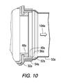
- FIG. 10 is an enlarged view of a portion of FIG. 8 .
- FIG. 1 shows a portion of an engine compartment 20 including an internal combustion engine 22 and a firewall 24 .
- Schematically shown at box 26 is a typical location for mounting an air cleaner assembly for supplying clean filtered combustion air to the engine, e.g. to the compressor portion of a turbocharger such as 28 , all as is known.
- an air cleaner assembly 30 includes a bracket 32 mounted to a designated component in the underhood engine compartment.
- a designated component is one or more of the mounting rails or platforms such as 34 , 36 provided by the engine manufacturer, FIGS. 1 , 2 . These mounting rails or platforms may be along the engine valve cover 38 .
- the air cleaner assembly may be mounted to one or more other designated components in the underhood engine compartment.
- Bracket 32 forms a combustion air flow passage 40 therethrough.
- An air filter 42 includes a housing 44 mounted to bracket 32 , to be further described, and having a dirty air inlet 46 and a clean air outlet 48 .
- a combustion air duct 50 FIGS.
- 3 , 5 has an inlet 52 receiving clean filtered combustion air through bracket 32 and supplying the clean combustion air to the engine.
- the clean air outlet 48 of the filter housing and the inlet 52 of combustion air duct 50 are each sealed at bracket 32 , FIG. 6 , such that clean filtered air exits the air filter at clean air outlet 48 of the filter housing and flows through the combustion air flow passage 40 of bracket 32 and through inlet 52 of combustion air duct 50 as clean combustion air supplied to the engine.
- clean air outlet 48 of the filter housing and inlet 52 of combustion air duct 50 are each sealed to bracket 32 at combustion air flow passage 40 .
- a clamp 54 such as a band clamp, provides clamping sealing pressure to at least one interface between combustion air flow passage 40 of bracket 32 , clean air outlet 48 of the filter housing, and inlet 52 of combustion air duct 50 .
- Bracket 32 has a sidewall 56 , FIGS. 5 , 6 , defining combustion air flow passage 40 .
- Sidewall 56 has first and second distally oppositely facing surfaces 58 and 60 . Clean air outlet 48 of the filter housing engages first surface 58 in sealing relation.
- Inlet 52 of combustion air duct 50 engages second surface 60 in sealing relation.
- One of the noted first and second surfaces of sidewall 56 e.g. first surface 58 , faces radially inwardly towards combustion air flow passage 40 .
- the other of the first and second surfaces of sidewall 56 e.g. second surface 60 , faces radially outwardly away from combustion air flow passage 40 .
- Each of clean air outlet 48 of the filter housing, sidewall 56 of combustion air flow passage 40 of bracket 32 , and inlet 52 of combustion air duct have respective axial extension sections 64 , 66 , 68 , FIGS. 5 , 6 , axially overlapping each other at an overlap region 70 .
- Axial extension section 66 of sidewall 56 of combustion air flow passage 40 of bracket 32 is sandwiched radially between axial extension section 64 of clean air outlet 48 of the filter housing and axial extension section 68 of inlet 52 of combustion air duct 50 at overlap region 70 .
- Band clamp 54 circumscribes axial extension section 68 of inlet 52 of combustion air duct 50 and axial extension section 66 of sidewall 56 of combustion air flow passage 40 of bracket 32 and axial extension section 64 of clean air outlet 48 of the filter housing at overlap region 70 .
- Clamp 54 is a first clamp located at a first clamping location 72 , FIG. 6 .
- a second clamp 74 is located at a second clamping location 76 and clamping and mounting the filter housing to bracket 32 .
- First and second clamping locations 72 and 76 are spaced and separate locations.
- a floating radial seal 77 is provided between axial extension section 66 of sidewall 56 of combustion air flow passage 40 of bracket 32 and axial extension section 64 of clean air outlet 48 of the filter housing.
- floating radial seal 77 is a resilient rubber or the like O-ring in a concave recess formed in surface 58 of sidewall 56 and permitting axial movement of axial extension sections 64 and 66 relative to each other.
- the filter housing has a first flange 78 extending radially outwardly from axial extension section 64 of clean air outlet 48 of the filter housing.
- Bracket 32 has a second flange 80 extending radially outwardly from axial extension section 66 of sidewall 56 of combustion air flow passage 40 of bracket 32 .
- First and second flanges 78 and 80 are axially spaced by an axial air gap 82 reducing heat transfer therebetween.
- filter housing 44 includes a cover 84 , FIG. 3 , detachably mounted to a base 86 at a third clamp 88 at a third clamping location 90 .
- Base 86 is mounted to bracket 32 by second clamp 74 .
- Third clamping location 90 is spaced and separate from first and second clamping locations 72 and 76 .
- dirty air inlet 46 is in cover 84 , FIG. 4
- clean air outlet 48 is in base 86 .
- An air filter element 92 in one embodiment having an inverted V-shape, though other air filter elements may be used, has an upstream dirty side 94 receiving dirty air from dirty air inlet 46 , and a downstream clean side 96 delivering clean filtered air to clean air outlet 48 .
- Air filter element 92 is integrally and permanently mounted to base 86 in one embodiment and defines a clean filtered air plenum 98 therebetween.
- base 86 and air filter element 92 are removed and replaced as a single unit from and to the filter housing. Air flows through the air filter element along a first flow path into clean filtered air plenum 98 and then flows along a second flow path to clean air outlet 40 .
- the first flow path is shown at arrows 102
- the second flown path is shown at arrow 104 .
- First and second flow paths 102 and 104 are in the same direction. While in the clean air plenum 98 , the flow may also extend along a transverse direction into and out of the page in FIG. 4 , which transitional flow path is shown at 106 in FIG. 7 .
- FIGS. 8-10 the first flow path is shown at 102 a flowing into dirty air inlet 46 a to be filtered by filter element 92 a in filter housing 44 a , whereafter the clean filtered air flows along a second flow path 104 a to clean air outlet 48 a .
- air flows through air filter element 92 a along first flow path 102 a into clean filtered air plenum 98 a after passing through filter element 92 a and then flows along second flow path 104 a to clean air outlet 48 a .
- first and second flow paths 102 a and 104 a are normal to each other. In the embodiment of FIGS.
- the filter housing may have a door such as 108 which may be removed to enable servicing of filter element 92 a , e.g. by pulling filter element 92 a horizontally leftwardly in FIG. 8 through open or removed door 108 , and then insertion of a replacement filter element horizontally rightwardly into the housing.
- Bracket 32 a may include a combustion air flow passage 40 a with sidewall 56 a sandwiched between clean air outlet 48 a of the filter housing and inlet 52 a of combustion air duct 50 a , clamped by band clamp 54 a , comparably to that above described for FIG. 6 .
- the system provides a combination air filter element 92 and base 86 for an air cleaner assembly 30 for an internal combustion engine 22 in an underhood engine compartment 20 .
- the air cleaner assembly has a bracket 32 mounted to a designated component, e.g. 34 and/or 36 , in the underhood engine compartment. Bracket 32 forms a combustion air flow passage 40 therethrough.
- the combination air filter element and base 92 , 86 is part of an air filter 42 including a housing 44 having a cover 84 detachably mounted to a base 86 .
- the housing is mounted to bracket 32 and has a dirty air inlet 46 and a clean air outlet 48 .
- the combination air filter element and base includes an air filter element 92 having an upstream dirty side 94 receiving dirty air from dirty air inlet 46 , and a downstream clean side 96 delivering clean filtered air to clean air outlet 48 .
- air filter element 92 is integrally and permanently mounted to base 86 and defines a clean filtered air plenum 98 therebetween.
- the combination air filter element and base 92 , 86 is removed and replaced as a single unit from and to the filter housing.
- a combustion air duct 50 having an inlet 52 receives clean filtered combustion air through bracket 32 and supplies the clean combustion air to the engine.
- Clean air outlet 48 of the filter housing and inlet 52 of combustion air duct 50 are each sealed at bracket 32 , such that clean filtered air exits the combination air filter element and base 92 , 86 at clean air outlet 48 of the filter housing and flows through combustion air flow passage 40 of bracket 32 and through inlet 52 of combustion air duct 50 as clean filtered combustion air supplied to the engine.
- the system provides a filter assembly 42 including a housing 44 having a cover 84 detachably mounted to a base 86 .
- the filter housing has a dirty fluid inlet 46 and a clean fluid outlet 48 .
- a filter element 92 has an upstream dirty side 94 receiving dirty fluid from inlet 46 , and a downstream clean side 96 delivering clean filtered fluid to outlet 48 .
- Filter element 92 is integrally and permanently mounted to base 86 and defines a clean filtered fluid plenum 98 therebetween. Base 86 and filter element 92 are removed and replaced as a single unit from and to housing 44 .
Abstract
Description
Claims (24)
Priority Applications (6)
| Application Number | Priority Date | Filing Date | Title |
|---|---|---|---|
| US13/229,835 US8535403B2 (en) | 2010-09-16 | 2011-09-12 | Filter assembly with mounting |
| DE112011103120T DE112011103120T5 (en) | 2010-09-16 | 2011-09-15 | Filter arrangement with holder |
| PCT/US2011/051677 WO2012037302A1 (en) | 2010-09-16 | 2011-09-15 | Filter assembly with mounting |
| BR112012032512A BR112012032512A2 (en) | 2010-09-16 | 2011-09-15 | air purifier assembly for internal combustion engine, combination air filter element and base and filter assembly. |
| CN201180037022.XA CN103052436B (en) | 2010-09-16 | 2011-09-15 | There is the filter assemblies of department of assembly |
| US14/317,020 US9387424B2 (en) | 2010-09-16 | 2014-06-27 | V-shaped filter and fixture |
Applications Claiming Priority (3)
| Application Number | Priority Date | Filing Date | Title |
|---|---|---|---|
| US38341910P | 2010-09-16 | 2010-09-16 | |
| US201161494503P | 2011-06-08 | 2011-06-08 | |
| US13/229,835 US8535403B2 (en) | 2010-09-16 | 2011-09-12 | Filter assembly with mounting |
Publications (2)
| Publication Number | Publication Date |
|---|---|
| US20120067323A1 US20120067323A1 (en) | 2012-03-22 |
| US8535403B2 true US8535403B2 (en) | 2013-09-17 |
Family
ID=45816476
Family Applications (3)
| Application Number | Title | Priority Date | Filing Date |
|---|---|---|---|
| US13/223,387 Active 2032-09-12 US8764870B2 (en) | 2010-09-16 | 2011-09-01 | V-shaped filter and fixture |
| US13/229,835 Expired - Fee Related US8535403B2 (en) | 2010-09-16 | 2011-09-12 | Filter assembly with mounting |
| US14/317,020 Active 2031-10-09 US9387424B2 (en) | 2010-09-16 | 2014-06-27 | V-shaped filter and fixture |
Family Applications Before (1)
| Application Number | Title | Priority Date | Filing Date |
|---|---|---|---|
| US13/223,387 Active 2032-09-12 US8764870B2 (en) | 2010-09-16 | 2011-09-01 | V-shaped filter and fixture |
Family Applications After (1)
| Application Number | Title | Priority Date | Filing Date |
|---|---|---|---|
| US14/317,020 Active 2031-10-09 US9387424B2 (en) | 2010-09-16 | 2014-06-27 | V-shaped filter and fixture |
Country Status (5)
| Country | Link |
|---|---|
| US (3) | US8764870B2 (en) |
| CN (2) | CN102958580A (en) |
| BR (2) | BR112012032198A2 (en) |
| DE (2) | DE112011103118B4 (en) |
| WO (2) | WO2012036940A1 (en) |
Cited By (7)
| Publication number | Priority date | Publication date | Assignee | Title |
|---|---|---|---|---|
| US9387424B2 (en) | 2010-09-16 | 2016-07-12 | Cummins Filtration Ip Inc. | V-shaped filter and fixture |
| US20170284346A1 (en) * | 2016-03-31 | 2017-10-05 | Honda Motor Co., Ltd. | Air cleaner for vehicle |
| US20190128220A1 (en) * | 2017-10-27 | 2019-05-02 | Indian Motorcycle International, LLC | Air box for a vehicle |
| US10369508B2 (en) | 2017-02-23 | 2019-08-06 | Baldwin Filters, Inc. | Filter with shield features |
| US10870074B2 (en) | 2015-07-15 | 2020-12-22 | Baldwin Filters, Inc. | Multi-component holding assembly for multi-panel air filter |
| US11135538B2 (en) * | 2012-11-01 | 2021-10-05 | Advanced Flow Engineering Inc. | Air intake assembly and methods thereof |
| US11236713B2 (en) * | 2018-07-12 | 2022-02-01 | Advanced Flow Engineering, Inc. | Sealed intake air system |
Families Citing this family (33)
| Publication number | Priority date | Publication date | Assignee | Title |
|---|---|---|---|---|
| US8926725B2 (en) * | 2012-07-31 | 2015-01-06 | Cummins Filtration Ip, Inc. | V-shaped filter with serviceable frames and cartridges |
| BR112015005591B8 (en) * | 2012-09-12 | 2022-08-02 | Camfil Ab | SUPPORT SCREEN, FILTER MEDIUM PACKAGE FOR A TYPE-V FILTER AND TYPE-V FILTER PACKAGE |
| WO2014040615A1 (en) | 2012-09-12 | 2014-03-20 | Camfil Ab | Filter assembly and filter assembly manufacturing method |
| TR201802909T4 (en) | 2012-09-21 | 2018-03-21 | Camfil Ab | V-type filter with support net structure. |
| CN202983409U (en) * | 2012-11-15 | 2013-06-12 | 创天昱科技(深圳)有限公司 | Double-face air outlet type air purifier |
| DE102014009887A1 (en) | 2013-07-12 | 2015-01-15 | Mann + Hummel Gmbh | Filter element, filter with a filter element and filter housing of a filter |
| DE102014009706A1 (en) | 2013-07-12 | 2015-01-15 | Mann + Hummel Gmbh | Filter element with holding surfaces, filter with a filter element and filter housing of a filter |
| JP6352076B2 (en) | 2013-07-12 | 2018-07-04 | マン ウント フンメル ゲゼルシャフト ミット ベシュレンクテル ハフツング | Filter element having handgrip element and filter having filter element |
| DE102014009026A1 (en) | 2013-07-12 | 2015-01-15 | Mann + Hummel Gmbh | Filter element with at least one guide web, filter with a filter element and filter housing of a filter |
| DE102013020286A1 (en) | 2013-12-09 | 2015-06-11 | Mann + Hummel Gmbh | Filter device for fluid and carrier element for at least one filter element |
| US10226727B2 (en) | 2014-06-03 | 2019-03-12 | Cummins Filtration Ip, Inc. | Filter assembly with cam-lock filter interface |
| US10441911B2 (en) | 2014-09-25 | 2019-10-15 | Camfil Ab | V-type filter frame |
| ES2709426T3 (en) * | 2014-09-25 | 2019-04-16 | Camfil Ab | V-type filter frame |
| DE102015004645A1 (en) * | 2015-04-15 | 2016-10-20 | Mann + Hummel Gmbh | Filter element, in particular for gas filtration |
| DE102015004643A1 (en) * | 2015-04-15 | 2016-10-20 | Mann + Hummel Gmbh | Filter element, in particular for gas filtration |
| DE102015108559A1 (en) * | 2015-05-29 | 2016-12-01 | Vorwerk & Co. Interholding Gmbh | Backwashable air filter |
| EP3871750A1 (en) * | 2015-07-15 | 2021-09-01 | Baldwin Filters, Inc. | Multi-component holding assembly for multi-panel air filter |
| US20210069629A1 (en) * | 2015-07-15 | 2021-03-11 | Baldwin Filters, Inc. | Filter with shield features |
| US10974188B2 (en) | 2015-07-15 | 2021-04-13 | Baldwin Filters, Inc. | Filter with shield features |
| DE102015009535A1 (en) | 2015-07-27 | 2017-02-02 | Mann + Hummel Gmbh | Filter housing for a fluid filter |
| JP6674025B2 (en) * | 2015-11-13 | 2020-04-01 | ダブリュ.エル.ゴア アンド アソシエイツ,インコーポレイティドW.L. Gore & Associates, Incorporated | Support member for filter pleated media |
| USD791837S1 (en) | 2016-02-01 | 2017-07-11 | Cummins Inc. | Accessory support bracket |
| WO2017135921A1 (en) * | 2016-02-01 | 2017-08-10 | Cummins Inc. | Accessory support brackets with airflow passages |
| USD791838S1 (en) | 2016-02-01 | 2017-07-11 | Cummins Inc. | Accessory support bracket assembly |
| DE112017000710T5 (en) | 2016-03-18 | 2018-10-31 | Cummins Filtration Ip, Inc. | Coupled stable filter assembly |
| WO2017192441A1 (en) * | 2016-05-02 | 2017-11-09 | Cummins Filtration Ip, Inc. | Filter with interlocking housing interface |
| GB2550356B (en) * | 2016-05-16 | 2021-11-17 | Bitfury Group Ltd | Filter for immersion cooling apparatus |
| JP6276831B2 (en) * | 2016-11-18 | 2018-02-07 | アマノ株式会社 | Dust collector |
| WO2018170075A1 (en) * | 2017-03-17 | 2018-09-20 | Cummins Filtration Ip, Inc. | External brace reinforcement structure for improved strength and performance of primary filter element |
| EP3498140B1 (en) * | 2017-12-14 | 2020-07-15 | Aktiebolaget Electrolux | Filter for a vacuum cleaner |
| CA3097014A1 (en) | 2018-04-23 | 2019-10-31 | Home Depot International, Inc. | Air filtration ceiling fan |
| US10926209B1 (en) * | 2020-06-05 | 2021-02-23 | Celios Corporation | Air filtration system, air filtration device, and air filtration module for use therewith |
| TW202348300A (en) * | 2022-03-19 | 2023-12-16 | 印度商艾羅菲爾過濾器印度私人有限公司 | Mini-pleat v cell filter |
Citations (22)
| Publication number | Priority date | Publication date | Assignee | Title |
|---|---|---|---|---|
| US2626010A (en) | 1951-04-05 | 1953-01-20 | Houdaille Hershey Corp | Air cleaner |
| US4207085A (en) | 1978-11-16 | 1980-06-10 | Ford Motor Company | Air cleaner air expansion chamber construction |
| US4440555A (en) | 1982-05-20 | 1984-04-03 | Clark Equipment Company | Engine compartment and air cleaner |
| US5474337A (en) | 1993-09-24 | 1995-12-12 | Donaldson Company, Inc. | Joint and seal system for air transfer tubes |
| US5609298A (en) | 1995-11-03 | 1997-03-11 | Hyslop; William J. | Exhaust nozzle assembly for an exhaust extraction system |
| US6375700B1 (en) | 2000-06-23 | 2002-04-23 | Nelson Industries, Inc. | Direct flow filter |
| US6814772B1 (en) * | 2002-09-13 | 2004-11-09 | Fleetguard, Inc. | Air cleaner with low profile outlet duct connection |
| US6846342B2 (en) | 2002-07-18 | 2005-01-25 | Freudenberg Nonwovens Limited Partnership | Filter pack having nonwoven filter media and nonwoven edge banding frame |
| US6890366B2 (en) * | 2003-04-17 | 2005-05-10 | Visteon Global Technologies, Inc. | Sealed engine air filter system |
| US6955696B1 (en) | 2003-07-31 | 2005-10-18 | Filtration Group, Inc. | Filter frame and assembly |
| US20050247034A1 (en) * | 2004-05-07 | 2005-11-10 | Sogefi Filtration Do Brasil Ltda. | Air filter assembly module |
| US20060064952A1 (en) * | 2004-09-29 | 2006-03-30 | Honda Motor Co., Ltd. | Intake system |
| US7179315B2 (en) * | 2004-08-04 | 2007-02-20 | Jui-Fa Huang | Vertical-shaft air filtering device having high flow rate and two-way air intake structure |
| US20080011673A1 (en) | 2005-09-01 | 2008-01-17 | Janikowski Eric A | Modified Direct Flow Filter |
| US20080040883A1 (en) | 2006-04-10 | 2008-02-21 | Jonas Beskow | Air Flow Losses in a Vacuum Cleaners |
| US20090084344A1 (en) * | 2007-09-27 | 2009-04-02 | Gm Global Technology Operations, Inc. | Air filter system for a vehicle and method for mounting the same |
| US7597735B2 (en) | 2006-12-21 | 2009-10-06 | Cummins Filtration Ip Inc. | Apparatus and system for uniform sealing force in an air filter assembly |
| US7691165B1 (en) | 2006-06-12 | 2010-04-06 | Frank Hammes | Fluid filter frame system and method |
| US20120047856A1 (en) * | 2010-08-30 | 2012-03-01 | Ford Global Technologies, Llc | Spring clamp for an air filter housing |
| US8287614B2 (en) * | 2009-08-10 | 2012-10-16 | Mann+Hummel Gmbh | Supplemental filter media support insert for an air cleaner |
| US8337579B2 (en) * | 2010-11-09 | 2012-12-25 | Honda Motor Company, Ltd. | Air cleaner assemblies and vehicles including same |
| US8404015B2 (en) * | 2007-12-21 | 2013-03-26 | Mann+Hummel Gmbh | Filter arrangement |
Family Cites Families (12)
| Publication number | Priority date | Publication date | Assignee | Title |
|---|---|---|---|---|
| DE2751640A1 (en) | 1977-11-17 | 1979-05-23 | Delbag Luftfilter Gmbh | REPLACEABLE FILTER ELEMENT, IN PARTICULAR FOR NUCLEAR SYSTEMS, FOR CLEANING AIR OR GAS FLOWS LOADED WITH TOXIC OR RADIOACTIVE COMPONENTS AND PROCEDURES FOR REPLACING AND REMOVING VOLUME FILTER REMOVAL |
| US4882055A (en) | 1986-09-11 | 1989-11-21 | Suratco Products Company | Unitary injection molded filter |
| DE9114496U1 (en) | 1991-11-21 | 1992-02-27 | Kluge, Klaus, Dipl.-Ing., 6070 Langen, De | |
| US6485538B1 (en) * | 1999-03-31 | 2002-11-26 | Yugen Caisha Infinity Kenkyusho | Air-conditioning air filter |
| US7588629B2 (en) | 2006-01-20 | 2009-09-15 | Aaf-Mcquay Inc. | Filter cassette |
| US7931726B2 (en) | 2006-03-01 | 2011-04-26 | Camfil Ab | Box-V filter and method of fabricating the same |
| US7740678B2 (en) | 2007-08-07 | 2010-06-22 | Cummins Filtration Ip, Inc. | High capacity filter |
| US8425644B2 (en) | 2008-01-31 | 2013-04-23 | Anders Sundvik | High flow V-bank filter |
| CN201193576Y (en) * | 2008-04-08 | 2009-02-11 | 重庆宗申技术开发研究有限公司 | Novel air filter |
| CN101424233B (en) * | 2008-11-18 | 2011-09-28 | 力帆实业(集团)股份有限公司 | Air filter |
| US20100126128A1 (en) | 2008-11-25 | 2010-05-27 | Scott Iii Richard J | Rigid cell filter assembly |
| US8764870B2 (en) * | 2010-09-16 | 2014-07-01 | Cummins Filtration Ip, Inc. | V-shaped filter and fixture |
-
2011
- 2011-09-01 US US13/223,387 patent/US8764870B2/en active Active
- 2011-09-07 WO PCT/US2011/050593 patent/WO2012036940A1/en active Application Filing
- 2011-09-07 BR BR112012032198A patent/BR112012032198A2/en not_active IP Right Cessation
- 2011-09-07 DE DE112011103118.1T patent/DE112011103118B4/en active Active
- 2011-09-07 CN CN2011800299696A patent/CN102958580A/en active Pending
- 2011-09-12 US US13/229,835 patent/US8535403B2/en not_active Expired - Fee Related
- 2011-09-15 DE DE112011103120T patent/DE112011103120T5/en not_active Withdrawn
- 2011-09-15 CN CN201180037022.XA patent/CN103052436B/en not_active Expired - Fee Related
- 2011-09-15 BR BR112012032512A patent/BR112012032512A2/en not_active IP Right Cessation
- 2011-09-15 WO PCT/US2011/051677 patent/WO2012037302A1/en active Application Filing
-
2014
- 2014-06-27 US US14/317,020 patent/US9387424B2/en active Active
Patent Citations (24)
| Publication number | Priority date | Publication date | Assignee | Title |
|---|---|---|---|---|
| US2626010A (en) | 1951-04-05 | 1953-01-20 | Houdaille Hershey Corp | Air cleaner |
| US4207085A (en) | 1978-11-16 | 1980-06-10 | Ford Motor Company | Air cleaner air expansion chamber construction |
| US4440555A (en) | 1982-05-20 | 1984-04-03 | Clark Equipment Company | Engine compartment and air cleaner |
| US5474337A (en) | 1993-09-24 | 1995-12-12 | Donaldson Company, Inc. | Joint and seal system for air transfer tubes |
| US5609298A (en) | 1995-11-03 | 1997-03-11 | Hyslop; William J. | Exhaust nozzle assembly for an exhaust extraction system |
| US6375700B1 (en) | 2000-06-23 | 2002-04-23 | Nelson Industries, Inc. | Direct flow filter |
| US6846342B2 (en) | 2002-07-18 | 2005-01-25 | Freudenberg Nonwovens Limited Partnership | Filter pack having nonwoven filter media and nonwoven edge banding frame |
| US6814772B1 (en) * | 2002-09-13 | 2004-11-09 | Fleetguard, Inc. | Air cleaner with low profile outlet duct connection |
| US6890366B2 (en) * | 2003-04-17 | 2005-05-10 | Visteon Global Technologies, Inc. | Sealed engine air filter system |
| US6955696B1 (en) | 2003-07-31 | 2005-10-18 | Filtration Group, Inc. | Filter frame and assembly |
| US20050247034A1 (en) * | 2004-05-07 | 2005-11-10 | Sogefi Filtration Do Brasil Ltda. | Air filter assembly module |
| US7179315B2 (en) * | 2004-08-04 | 2007-02-20 | Jui-Fa Huang | Vertical-shaft air filtering device having high flow rate and two-way air intake structure |
| US20060064952A1 (en) * | 2004-09-29 | 2006-03-30 | Honda Motor Co., Ltd. | Intake system |
| US7465329B2 (en) * | 2004-09-29 | 2008-12-16 | Honda Motor Co., Ltd. | Intake system |
| US20080011673A1 (en) | 2005-09-01 | 2008-01-17 | Janikowski Eric A | Modified Direct Flow Filter |
| US20080040883A1 (en) | 2006-04-10 | 2008-02-21 | Jonas Beskow | Air Flow Losses in a Vacuum Cleaners |
| US7691165B1 (en) | 2006-06-12 | 2010-04-06 | Frank Hammes | Fluid filter frame system and method |
| US7597735B2 (en) | 2006-12-21 | 2009-10-06 | Cummins Filtration Ip Inc. | Apparatus and system for uniform sealing force in an air filter assembly |
| US20090084344A1 (en) * | 2007-09-27 | 2009-04-02 | Gm Global Technology Operations, Inc. | Air filter system for a vehicle and method for mounting the same |
| US8236079B2 (en) * | 2007-09-27 | 2012-08-07 | GM Global Technology Operations LLC | Air filter system for a vehicle and method for mounting the same |
| US8404015B2 (en) * | 2007-12-21 | 2013-03-26 | Mann+Hummel Gmbh | Filter arrangement |
| US8287614B2 (en) * | 2009-08-10 | 2012-10-16 | Mann+Hummel Gmbh | Supplemental filter media support insert for an air cleaner |
| US20120047856A1 (en) * | 2010-08-30 | 2012-03-01 | Ford Global Technologies, Llc | Spring clamp for an air filter housing |
| US8337579B2 (en) * | 2010-11-09 | 2012-12-25 | Honda Motor Company, Ltd. | Air cleaner assemblies and vehicles including same |
Non-Patent Citations (1)
| Title |
|---|
| International Preliminary Report on Patentability, PCT/US2011/051677, date of mailing Mar. 28, 2013. |
Cited By (11)
| Publication number | Priority date | Publication date | Assignee | Title |
|---|---|---|---|---|
| US9387424B2 (en) | 2010-09-16 | 2016-07-12 | Cummins Filtration Ip Inc. | V-shaped filter and fixture |
| US11135538B2 (en) * | 2012-11-01 | 2021-10-05 | Advanced Flow Engineering Inc. | Air intake assembly and methods thereof |
| US10870074B2 (en) | 2015-07-15 | 2020-12-22 | Baldwin Filters, Inc. | Multi-component holding assembly for multi-panel air filter |
| US20170284346A1 (en) * | 2016-03-31 | 2017-10-05 | Honda Motor Co., Ltd. | Air cleaner for vehicle |
| US10508625B2 (en) * | 2016-03-31 | 2019-12-17 | Honda Motor Co., Ltd. | Air cleaner for vehicle |
| US10369508B2 (en) | 2017-02-23 | 2019-08-06 | Baldwin Filters, Inc. | Filter with shield features |
| US20190128220A1 (en) * | 2017-10-27 | 2019-05-02 | Indian Motorcycle International, LLC | Air box for a vehicle |
| US10760536B2 (en) * | 2017-10-27 | 2020-09-01 | Indian Motorcycle International, LLC | Air box for a vehicle |
| US11236713B2 (en) * | 2018-07-12 | 2022-02-01 | Advanced Flow Engineering, Inc. | Sealed intake air system |
| US20220128021A1 (en) * | 2018-07-12 | 2022-04-28 | Advanced Flow Engineering, Inc. | Sealed intake air system |
| US11761410B2 (en) * | 2018-07-12 | 2023-09-19 | Advanced Flow Engineering, Inc. | Sealed intake air system |
Also Published As
| Publication number | Publication date |
|---|---|
| US20120067013A1 (en) | 2012-03-22 |
| DE112011103118T5 (en) | 2013-08-01 |
| US8764870B2 (en) | 2014-07-01 |
| WO2012036940A1 (en) | 2012-03-22 |
| DE112011103118B4 (en) | 2022-01-27 |
| CN102958580A (en) | 2013-03-06 |
| BR112012032198A2 (en) | 2016-11-22 |
| BR112012032512A2 (en) | 2017-10-10 |
| WO2012037302A1 (en) | 2012-03-22 |
| DE112011103120T5 (en) | 2013-08-01 |
| CN103052436B (en) | 2015-09-09 |
| US20140305087A1 (en) | 2014-10-16 |
| US9387424B2 (en) | 2016-07-12 |
| CN103052436A (en) | 2013-04-17 |
| US20120067323A1 (en) | 2012-03-22 |
Similar Documents
| Publication | Publication Date | Title |
|---|---|---|
| US8535403B2 (en) | Filter assembly with mounting | |
| CN101815570B (en) | Filter element having serrated seal | |
| US9192885B2 (en) | Intake air filter for internal combustion engines | |
| US8518139B2 (en) | Filter device for filtering gaseous fluids | |
| US8673043B2 (en) | Fluid filter | |
| US10105630B2 (en) | Hollow filter element of a filter for filtering fluid, filter, filter housing, and seal of a hollow filter element | |
| AU2013293139B2 (en) | Filter housing, fluted filter and safety filter | |
| CN103706157B (en) | The support meanss of the flat filter element of filter, filter and filter | |
| JP6094398B2 (en) | Manufacturing method of oil mist separator | |
| CN101815568A (en) | Filter element having V-seal | |
| CN104136729A (en) | Exhaust gas purification device | |
| US20160129385A1 (en) | Filter, Hollow Filter Element, and Filter Housing of a Filter, and Seal of a Hollow Filter Element | |
| US20160305375A1 (en) | Filter assembly | |
| US9745876B2 (en) | Oil filter systems | |
| US8632618B2 (en) | Filter assembly with housing structure | |
| US8147578B2 (en) | Reduced restriction air filter | |
| JP2015117590A (en) | Exhaust system component attachment structure of engine, and exhaust system component attachment method of engine | |
| US7867311B1 (en) | Filter assembly with trapped auxiliary flow component | |
| AU2017379787A1 (en) | Filter with preformed end caps having notch feature | |
| JP5920381B2 (en) | Intake and exhaust system for internal combustion engine | |
| GB2479810A (en) | Air purifier having resonator installed in the air outlet | |
| JP2006037910A (en) | Intake structure for engine | |
| US20170319997A1 (en) | Filter element | |
| US7758677B2 (en) | Filtering device | |
| JP3724642B2 (en) | Intake device |
Legal Events
| Date | Code | Title | Description |
|---|---|---|---|
| AS | Assignment |
Owner name: CUMMINS FILTRATION IP INC., MINNESOTA Free format text: ASSIGNMENT OF ASSIGNORS INTEREST;ASSIGNORS:PATWARDHAN, HRISHIKESH;SCHWARTZ, SCOTT W.;HOVERSON, GREGORY W.;SIGNING DATES FROM 20110816 TO 20110826;REEL/FRAME:026925/0033 |
|
| STCF | Information on status: patent grant |
Free format text: PATENTED CASE |
|
| FPAY | Fee payment |
Year of fee payment: 4 |
|
| FEPP | Fee payment procedure |
Free format text: MAINTENANCE FEE REMINDER MAILED (ORIGINAL EVENT CODE: REM.); ENTITY STATUS OF PATENT OWNER: LARGE ENTITY |
|
| LAPS | Lapse for failure to pay maintenance fees |
Free format text: PATENT EXPIRED FOR FAILURE TO PAY MAINTENANCE FEES (ORIGINAL EVENT CODE: EXP.); ENTITY STATUS OF PATENT OWNER: LARGE ENTITY |
|
| STCH | Information on status: patent discontinuation |
Free format text: PATENT EXPIRED DUE TO NONPAYMENT OF MAINTENANCE FEES UNDER 37 CFR 1.362 |
|
| FP | Lapsed due to failure to pay maintenance fee |
Effective date: 20210917 |