US8547389B2 - Capturing image structure detail from a first image and color from a second image - Google Patents
Capturing image structure detail from a first image and color from a second image Download PDFInfo
- Publication number
- US8547389B2 US8547389B2 US12/754,530 US75453010A US8547389B2 US 8547389 B2 US8547389 B2 US 8547389B2 US 75453010 A US75453010 A US 75453010A US 8547389 B2 US8547389 B2 US 8547389B2
- Authority
- US
- United States
- Prior art keywords
- image
- source
- color
- target
- pixel
- Prior art date
- Legal status (The legal status is an assumption and is not a legal conclusion. Google has not performed a legal analysis and makes no representation as to the accuracy of the status listed.)
- Expired - Fee Related, expires
Links
- 238000000034 method Methods 0.000 claims abstract description 62
- 238000009826 distribution Methods 0.000 claims abstract description 39
- 238000002156 mixing Methods 0.000 claims description 46
- 238000012546 transfer Methods 0.000 claims description 46
- 230000008569 process Effects 0.000 description 26
- 238000005516 engineering process Methods 0.000 description 18
- 239000000243 solution Substances 0.000 description 13
- 230000007704 transition Effects 0.000 description 12
- 230000000007 visual effect Effects 0.000 description 11
- 230000000875 corresponding effect Effects 0.000 description 9
- 238000005315 distribution function Methods 0.000 description 8
- 238000013459 approach Methods 0.000 description 7
- 238000010276 construction Methods 0.000 description 7
- 230000006870 function Effects 0.000 description 7
- 238000004422 calculation algorithm Methods 0.000 description 5
- 239000011159 matrix material Substances 0.000 description 4
- 238000007781 pre-processing Methods 0.000 description 4
- 238000012545 processing Methods 0.000 description 4
- 230000001186 cumulative effect Effects 0.000 description 3
- 238000010586 diagram Methods 0.000 description 3
- 238000012952 Resampling Methods 0.000 description 2
- 230000004075 alteration Effects 0.000 description 2
- 238000004458 analytical method Methods 0.000 description 2
- 238000003491 array Methods 0.000 description 2
- 238000004364 calculation method Methods 0.000 description 2
- 239000003086 colorant Substances 0.000 description 2
- 230000007547 defect Effects 0.000 description 2
- 238000003384 imaging method Methods 0.000 description 2
- 238000012986 modification Methods 0.000 description 2
- 230000004048 modification Effects 0.000 description 2
- 230000004044 response Effects 0.000 description 2
- 238000005070 sampling Methods 0.000 description 2
- 230000003068 static effect Effects 0.000 description 2
- 230000002238 attenuated effect Effects 0.000 description 1
- 230000009286 beneficial effect Effects 0.000 description 1
- 230000008901 benefit Effects 0.000 description 1
- 230000008859 change Effects 0.000 description 1
- 239000003795 chemical substances by application Substances 0.000 description 1
- 238000012937 correction Methods 0.000 description 1
- 230000002596 correlated effect Effects 0.000 description 1
- 230000007423 decrease Effects 0.000 description 1
- 238000005562 fading Methods 0.000 description 1
- 238000013507 mapping Methods 0.000 description 1
- 239000000203 mixture Substances 0.000 description 1
- 238000005457 optimization Methods 0.000 description 1
- 230000000644 propagated effect Effects 0.000 description 1
- 239000012088 reference solution Substances 0.000 description 1
- 230000001932 seasonal effect Effects 0.000 description 1
- 239000004065 semiconductor Substances 0.000 description 1
- 238000004088 simulation Methods 0.000 description 1
- 230000003595 spectral effect Effects 0.000 description 1
- 230000002123 temporal effect Effects 0.000 description 1
Images


Classifications
-
- G—PHYSICS
- G06—COMPUTING; CALCULATING OR COUNTING
- G06T—IMAGE DATA PROCESSING OR GENERATION, IN GENERAL
- G06T5/00—Image enhancement or restoration
- G06T5/50—Image enhancement or restoration by the use of more than one image, e.g. averaging, subtraction
-
- G—PHYSICS
- G06—COMPUTING; CALCULATING OR COUNTING
- G06T—IMAGE DATA PROCESSING OR GENERATION, IN GENERAL
- G06T11/00—2D [Two Dimensional] image generation
- G06T11/001—Texturing; Colouring; Generation of texture or colour
-
- G—PHYSICS
- G06—COMPUTING; CALCULATING OR COUNTING
- G06T—IMAGE DATA PROCESSING OR GENERATION, IN GENERAL
- G06T17/00—Three dimensional [3D] modelling, e.g. data description of 3D objects
- G06T17/05—Geographic models
-
- G—PHYSICS
- G06—COMPUTING; CALCULATING OR COUNTING
- G06T—IMAGE DATA PROCESSING OR GENERATION, IN GENERAL
- G06T2207/00—Indexing scheme for image analysis or image enhancement
- G06T2207/10—Image acquisition modality
- G06T2207/10024—Color image
-
- G—PHYSICS
- G06—COMPUTING; CALCULATING OR COUNTING
- G06T—IMAGE DATA PROCESSING OR GENERATION, IN GENERAL
- G06T2207/00—Indexing scheme for image analysis or image enhancement
- G06T2207/10—Image acquisition modality
- G06T2207/10032—Satellite or aerial image; Remote sensing
-
- G—PHYSICS
- G06—COMPUTING; CALCULATING OR COUNTING
- G06T—IMAGE DATA PROCESSING OR GENERATION, IN GENERAL
- G06T2207/00—Indexing scheme for image analysis or image enhancement
- G06T2207/20—Special algorithmic details
- G06T2207/20016—Hierarchical, coarse-to-fine, multiscale or multiresolution image processing; Pyramid transform
Definitions
- Multiresolution datasets often incorporate several sources of imagery at different scales. For instance, satellite images can be provided at a coarse resolution and aerial photographic images can be used at finer resolutions. Zooming within these maps may reveal jarring transitions.
- the data sources from which images are drawn often vary significantly in appearance due to differences in spectral response, seasonal changes, lighting and shadows, and custom image processing.
- zooming in or out within a multiresolution image pyramid often results in abrupt changes in appearance (i.e. temporal “popping”).
- spatial discontinuities may be observed in static perspective views, as such views access several image pyramid levels simultaneously.
- the method can include obtaining an image captured as a coarse image of a defined subject and a fine image of the defined subject.
- the fine image can be downsampled to create a temporary image.
- a further operation is applying a structure transfer operation to the temporary image to transfer color detail from the coarse image. The structure transfer takes place while retaining structural detail from the temporary image.
- a blending operation can be applied between the temporary image and the fine image to construct an intermediate image for at least one intermediate level in the multi-resolution image pyramid between the fine image and the coarse image.
- a method can generate an image that includes image structure detail captured from a first image and color from a second image.
- the first image of a defined subject can be obtained from a computer memory.
- the first image may be a downsampled fine image with image detail.
- the second image captured of the defined subject in the first image can be obtained from a computer memory.
- the second image may be a coarse image.
- a target pixel in the second image can be selected.
- a target color distribution for a pixel window of the target pixel can then be computed.
- a source color distribution for a pixel window of a corresponding pixel in the first image can be computed using a computer processor.
- a statistic of the target pixel can be determined with respect to the target color distribution.
- the source color in the source color distribution can be computed with the statistic.
- the target pixel color can then be replaced by the source color.
- FIG. 1 illustrates an embodiment of multi-resolution image pyramid with multiple resolutions of an upsampled image.
- FIG. 2 is a flowchart illustrating an overview of a method for generating a multi-resolution image pyramid in an embodiment.
- FIG. 3 is a block diagram illustrating an embodiment of a method for creating a multi-resolution image pyramid.
- FIG. 4 is an illustration of an embodiment of the z-score and rank properties that may be used for windowing transfer calculations.
- FIG. 5 is flowchart illustrating an embodiment of a method for generating an image that includes image structure detail from a fine image and color from a coarse image.
- FIG. 6 is a chart illustrating an embodiment of a process used in clipped Laplacian blending.
- FIG. 7 illustrates an embodiment of a process for an efficient blending method for clipped Laplacian blending.
- FIG. 8 is a flow chart illustrating an embodiment of efficient operations for generating a multi-resolution image pyramid used in visual transitions across multiple viewing scales.
- FIG. 9 is a block diagram illustrating an embodiment of modules that may be used for generating a multi-resolution image pyramid used in visual transitions across multiple viewing scales.
- a visually smooth image pyramid can be created that combines different data sources at different scales.
- Such image pyramids are used to transition between lower resolution images and higher resolution images in computer generated image environments.
- Examples of such computer generated image environments may include: simulations, games, maps, medical images, and other environments where a smooth transition is desired between a coarse resolution image and a fine resolution image.
- the input imagery for the image pyramid exists at a subset of levels and the imagery may already be spatially stitched together using existing stitching techniques. While the problem of creating an image pyramid may seem simple, several straightforward approaches have drawbacks. One simplistic idea is to downsample the fine imagery all the way to the coarsest level of the pyramid, overwriting any coarser image content. Downsampling or sub-sampling is the process of reducing the sampling frequency for an image created from an original graphic image. However, fine-scale imagery is often sparsely defined, and the resulting coarser levels may have a non-uniform appearance. Instead, it is desirable to preserve the spatial consistency of the coarse-scale image.
- Another possible approach is to modify the fine-scale imagery to have the same color appearance as the coarse-scale content.
- the color histogram of the fine image is often richer and the color histogram of the fine image may be preferred.
- the differences in appearance at the edges of images and across levels of an image pyramid can be noticeable in static perspective views.
- the solution of replacing coarse pyramid levels by downsampling the sparse fine imagery may lead to a patchwork appearance at coarser levels.
- the present technology can create an image pyramid 100 with multiple resolutions of an upsampled image, as illustrated in FIG. 1 , from stitched imagery at several scales that provides smoother visual transitions when zooming occurs.
- the present technology provides techniques that improve the transitions between images.
- One technique called structure transfer is a nonlinear operator that combines the detail of one image with the local appearance of another image. This operation can be used to inject detail from a fine image 130 into a coarse image 110 while retaining color consistency.
- the improved structural similarity provided in intermediate resolution images 120 from the structure transfer operation significantly reduces inter-level ghosting artifacts.
- the second technique can be called clipped Laplacian blending and this blending technology can be an efficient construction to minimize blur when creating intermediate levels. Such blending considers the sum of all inter-level image differences within the pyramid.
- This process can simultaneously satisfy both multi-resolution and spatial continuity. As a result, the visual differences between adjacent levels of the image pyramid can be minimized. In addition, the color characteristics of both the coarse and fine imagery can be preserved.
- MSE mean squared error
- a structure transfer operation can be used to maximize structural compatibility. This operation can modify the coarse image to inherit the detail of the fine image while preserving its original local color characteristics.
- the sum of all inter-level image differences within the pyramid can be minimized using the MSE metric.
- This difference function can be defined judiciously to avoid signal blurring.
- FIG. 2 is a flowchart illustrating a high level overview of an embodiment of a method for generating a multi-resolution image pyramid.
- the method can include the operation of obtaining an image captured as a coarse image of a defined subject, as in block 210 .
- An example of a coarse image is a satellite image of certain geographic area (e.g., a Landsat image) or a coarse texture that is applied to a 3-D geometric object.
- An image can also be captured as a fine image of the defined subject, as in block 220 .
- An example of a coarse image is an aerial photographic image of the same geographic area as the coarse image or a fine texture that is applied to a 3-D geometric object.
- the coarse image and fine image of the defined subject can be obtained from a computer readable storage medium or a computer memory.
- the fine image can then be downsampled to create a temporary image, as in block 230 .
- a structure transfer operation can then be applied to the temporary image to transfer color detail from the coarse image, while retaining structural detail from the temporary image, as in block 240 .
- a blending operation can be applied between the temporary image and the fine image to construct an intermediate image for at least one intermediate level in the multi-resolution image pyramid between the fine image and the coarse image, as in block 250 .
- the operations of applying a structure transfer operation and applying a blending operation to the temporary image can be performed on a server by a computer processor.
- the blending operation can be clipped Laplacian blending.
- the Laplacian blending may include applying a blending operation that blends a Laplacian pyramid from the fine image with a Laplacian image generated from the coarse image.
- a fine Laplacian image pyramid can be formed that has a plurality of downsampled images from the fine image.
- a coarse Laplacian image pyramid can be constructed from a plurality of downsampled images from the coarse image.
- a Laplacian pyramid represents a single image as a sum of detail at different resolution levels.
- a Laplacian pyramid is a bandpass image pyramid obtained by forming images representing the difference between successive levels of the Gaussian pyramid.
- one or more intermediate images for the multi-resolution pyramid can be generated by blending the corresponding levels of the coarse Laplacian pyramid and fine Laplacian pyramid from the root level (coarsest level) to the level of the coarse image (described in more detail later with FIG. 6 ).
- the Laplacian pyramid levels at resolutions equal to or coarser than the coarse image are blended together according to an alpha parameter ⁇ .
- the Laplacian pyramid levels at resolution levels greater than the coarse image are taken only from the Laplacian pyramid of the fine image.
- the intermediate image can then be constructed by summing the resulting Laplacian pyramid levels. For example, x (c+1) is the sum of the blended Laplacian pyramid L (c+1) .
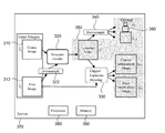
- FIG. 3 A block diagram of the process for creating a multi-resolution image pyramid is illustrated in FIG. 3 .
- a coarse image 310 can be combined with the downsampled 322 version of the fine image 312 using structure transfer 320 .
- the structure transfer operation will be described in more detail later.
- clipped Laplacian blending 330 creates the intermediate levels.
- the structure-transferred coarse image 350 (or temporary image) is downsampled 340 so that its new detail structure is propagated to even coarser levels 360 .
- the image pyramid construction is performed using preprocessing of the images. So any 2D or 3D client renderer need not be modified to benefit from the improved multi-resolution continuity.
- the pre-processing can take place on a server 370 or a computing cloud that has a plurality of processors 380 and memory 390 to service the pre-processing modules or operations described above. Alternatively, the pre-processing described may be embedded in firmware or special purpose hardware.
- an interpolatory bicubic filter may be used, which is also known as Catmull-Rom interpolation.
- This filter is a tensor product of two 1D filters. Evaluated on the pyramid, each 1D filter has weights ( ⁇ 9 111 29 ⁇ 3)/128 and ( ⁇ 3 29 111 ⁇ 9)/128 on alternate pixels.
- the image computation can be performed in a desired color space (e.g., Lab color space or RGB (Red, Green, and Blue)).
- the inputs to the process can be coarse and fine images ⁇ circumflex over (x) ⁇ c and ⁇ circumflex over (x) ⁇ f , respectively, and the output can be image pyramid levels ⁇ x l ⁇ .
- the goal can be to minimize visual differences between successive pyramid levels, while preserving the color characteristics of the coarser pyramid levels.
- the first term sums the mean structural similarity (MSSIM) of all adjacent pyramid levels.
- MSSIM(x, y) of two images x, y is the mean SSIM over all corresponding N ⁇ N (e.g., 11 ⁇ 11) pixel neighborhoods u ⁇ x, v ⁇ y.
- the luminance similarity l, the contrast similarity c, and the structure comparisons are defined in terms of the mean colors ⁇ , standard deviations ⁇ , and covariance ⁇ uv of the neighborhoods:
- SSIM ⁇ ( u , v ) ( 2 ⁇ ⁇ u ⁇ ⁇ y + c 1 ) ⁇ ( 2 ⁇ ⁇ uv + c 2 ) ( ⁇ u 2 + ⁇ v 2 + c 1 ) ⁇ ( ⁇ u 2 + ⁇ v 2 + c 2 ) .
- the SSIM can be computed over each color channel independently and the mean of the channels can then be taken.
- the MSSIM measure reaches a maximum value of 1.0 when two images are identical.
- the second term of equation (1) measures the color similarity of the original and modified coarse image levels. Specifically, the mean luminance-contrast similarity keeps only the first two factors:
- Mlc ⁇ ( x , y ) 1 ⁇ x ⁇ ⁇ ⁇ u ⁇ x , v ⁇ y ⁇ ⁇ l ⁇ ( u , v ) ⁇ c ⁇ ( u , v ) , and thus ignores structural detail. Because the finer image x f is unaltered in this construction, it may be unnecessary to measure the finer image's color fidelity.
- Step 1 Replace ⁇ circumflex over (x) ⁇ c by x c to maximize
- Ms ⁇ ( x , y ) 1 ⁇ x ⁇ ⁇ ⁇ u ⁇ x , v ⁇ y ⁇ ⁇ s ⁇ ( u , v ) .
- This first step finds a new coarse image that is structurally similar to the downsampled fine image but whose color characteristics match those of the input coarse image ⁇ circumflex over (x) ⁇ c .
- the structure transfer process is a fast local algorithm that approximates finding a new coarse image that is structurally similar to the downsampled fine image and the structure transfer process will be described in further detail later.
- Step 2 Create the temporary image levels as
- the structural compatibility provided by Step 1 can construct the temporary images using the simpler (linear) MSE metric. Furthermore, clipped Laplacian blending provides a fast approximate solution to this optimization and this will be described in more detail later.
- Step 3 Replace the coarser levels by downsampling x c .
- imagery is typically captured at the limit of the acquisition resolution device, and may therefore have any number of defects such as chromatic aberration, sensor noise, or demosaicing error.
- defects such as chromatic aberration, sensor noise, or demosaicing error.
- the technology can find a new coarse image x c that combines (1) the structural detail of the downsampled fine image D f c ⁇ circumflex over (x) ⁇ f and (2) the local color distribution of the original coarse image ⁇ circumflex over (x) ⁇ c .
- each color channel of the image will be processed separately.
- a model can be built for the local distribution of colors in the neighborhood of each pixel in both images, and a property of the center pixel can be used with respect to the center pixel's neighborhood in the structure image S to select the color value with the identical property in the neighborhood in the color image C.
- Two properties that may be used for such calculations may be the statistical z-score and rank properties, as illustrated in FIG. 4 .
- the computation can be performed separately for each color channel.
- the Rank process will be discussed first.
- the cumulative distribution functions (CDF) S and C can be computed for each pixel for values in the image neighborhood of S and C respectively.
- This local rank transfer can be viewed as a windowed histogram transfer operation, which aims to precisely reproduce the color channel distributions in C. While the Rank process is useful, the process may introduce additional noise.
- Z-score Another method of windowing transfer is the Z-score.
- Useful results can be obtained by transferring a z-score for pixel windows (i.e., approximating the local probability distribution function by a Gaussian).
- the mean ⁇ S and standard deviation ⁇ S of the neighborhood in the structure image are computed.
- the contributions of pixels in the window can be weighted using a 2D Gaussian.
- Useful results can be obtained in one example embodiment with a standard deviation of 5 pixels (over a window of 23 2 pixels).
- the z-score transfer approximates the maximization of equation (2), because the z-score transfer preserves the local luminance (mean value ⁇ ) and contrast ( ⁇ ) of the color image C while altering the detail (z-scores) to correlate with the structure image S.
- the z-score technique is a greedy approximation in that the technique processes each pixel independently, while ignoring how the neighboring pixel values are simultaneously modified. In other embodiments, a more integrated or less greedy transfer process can be used.
- FIG. 5 illustrates an example process of the method for using the structure transfer described for generating an image that includes image structure detail from a fine image and color from a coarse image.
- An image can be obtained that is captured as a coarse image of a defined subject from a computer memory, as in block 510 .
- Another image can be obtained that has been captured as a fine image of the defined subject in the coarse image from a computer memory, as in block 520 .
- An example of the coarse image is a satellite photo and an example of the fine image is an aerial photo.
- the fine image can be downsampled to create a temporary image, as in block 530 .
- a target pixel in the temporary image can be selected, as in block 540 .
- a target color distribution for a pixel window of the target pixel can be computed on a per-channel basis, as in block 550 .
- the pixel window can be various shapes as desired.
- the pixel window may be a square region centered about the target pixel, a circular region or another useful region shape.
- the target color distribution can be obtained by non-uniformly weighting a contribution of pixels in the pixel window of the target pixel.
- the source color distribution can be obtained by the same non-uniform weighting of contributions of pixels in the pixel window of the corresponding source pixel.
- the non-uniform weighting can be based on a 2D (two-dimensional) spatial Gaussian function centered at the target pixel.
- the source color distribution can be determined on a per-channel basis for a pixel window of a corresponding pixel in the coarse image using a computer processor, as in block 560 .
- the structure transfer algorithm can be performed on a “per-channel” basis for an image that has multiple color channels.
- the image may also be transformed into a different color space than the image's original color space to improve the results of structure transfer.
- the input images may be in an RGB (Red, Green, Blue) color space, and then the images may be transformed into the Lab color space to improve the structure transfer. More generally, structure transfer can be performed in any color space.
- a statistic of the target pixel with respect to the target color distribution can be computed, as in block 570 .
- a target pixel's rank can be identified in a cumulative distribution function for a pixel window of the temporary image. Finding the target color distribution and the source color distribution for corresponding pixel windows enables a localized windowed histogram transfer operation to occur for a plurality of target pixels in the temporary image, and allows the target pixel color to be replaced by the source color from the coarse image.
- the source color in the source color distribution can be computed with the statistic, as in block 580 .
- the source color can be selected using the target pixel's rank in the cumulative distribution function for the pixel window in the coarse image and that rank can be applied to the target pixel in the temporary image to select the source color applied to the target pixel.
- the target pixel color can then be replaced by the source color, as in block 590 .
- These operations can also be called a windowed local color statistic transfer operation.
- the source color to be applied to the target pixel can be identified by applying a color from the correlated pixel in a coarse image that has the same standard deviation in the pixel window as the target pixel in the temporary image.
- a color probability distribution function can be used such as a Gaussian probability distribution function. Accordingly, a z-score can be computed for a target pixel's color in a color probability distribution function for a local pixel window. Then the z-score can be applied to the color probability distribution function for the source's local pixel window of a corresponding pixel in the coarse image in order to select the source color from the coarse image that is applied to the target pixel.
- MSE(x l , x l+1 ) The precise definition of the mean squared error term MSE(x l , x l+1 ) is relevant. Two definitions can be considered. The first approach corresponds to a simple form of linear interpolation and leads to undesirable blurring. The second approach, which is defined here as clipped Laplacian blending is better able to preserve image detail.
- equation (4) defines a sparse linear system
- the linear system can be solved using an iterative solver.
- D and upsampling filter U the global minimum of equation (4) can be directly obtained using more efficient algorithms.
- the factor 4 ⁇ l accounts for the number of pixels at level l when computing the mean error.
- minimizing equation (5) seeks to make every pixel of the finer image look like a magnified version of the coarser image.
- the downsampling of each image should be a blended combination of the next-coarser image and the twice-downsampled next-finer image.
- L k x 1 ⁇ ( 1 - ⁇ 1 ) ⁇ L k x c + ⁇ l ⁇ L k x f k ⁇ c L k x f k > c , ( 10 ) where ⁇ l is defined as in equation (7).
- the process can be called clipped Laplacian blending as illustrated in FIG. 6 .
- Clipped Laplacian blending creates intermediate-resolution images by smoothly transitioning the coarse levels of the Laplacian pyramids while iteratively adding intact fine detail. If the two Laplacian pyramids were blended across all levels, this would recreate the less effective solution described that uses simple linear interpolation.
- Each temporary image can be reconstructed as:
- Solution form 2 The same solution can also be obtained by linearly blending the coarse image x c with the coarse version c x f of the fine image, and adding back the Laplacian detail L c+1 x f . . . L l x f of the fine image:
- FIG. 7 illustrates the process as an efficient blending algorithm with 3 steps: (1) downsampling to form Gaussian pyramid 710 , (2) coarse-level differencing 720 , and (3) fading the difference into the pyramid 730 .
- FIG. 8 is a flowchart illustrating efficient operations for generating a multi-resolution image pyramid used in visual transitions across multiple viewing scales.
- a coarse image and a fine image of a defined subject can be obtained from a computer memory, as in block 810 and 820 .
- a Gaussian image pyramid with a plurality of downsampled images can be generated using the fine image, as block 830 .
- a temporary image can be defined as a level within the Gaussian image pyramid that has a same resolution as the coarse image, and an intermediate image can be defined that is a copy of the temporary image, as in block 840 .
- a structure transfer operation can then be applied to the intermediate image to transfer color detail from the coarse image to the intermediate image, as in block 850 .
- the use of the structure transfer operation is an optional part of the process as shown by the dotted line in FIG. 8 , and the clipped Laplacian blending method can be used independent from the structure transfer method.
- a difference image can be generated or computed from a difference between the intermediate image with structure transferred details and the temporary image, as in block 860 .
- a difference image can then be upsampled into successively finer levels of the Gaussian image pyramid.
- the difference image can be upsampled for each pyramid level and the upsampled difference image can be blended into each image at each level of the Gaussian image pyramid.
- the difference image can be blended into the Gaussian image pyramid with alpha blending (i.e., linear interpolation), as in block 870 .
- the alpha blending can be a graded amount of alpha blending, and the graded alpha blending can increase as the size of the downsampled images in the Gaussian image pyramid decreases.
- the graded amount of alpha blending at each level can be defined by
- FIG. 9 illustrates a system for generating a multi-resolution image pyramid used in visual transitions.
- Each of the modules described below may be a hardware module that performs the specified processes.
- each of the modules may be a server with a plurality of processors that are networked together to perform the desired processes for the module.
- An example of this may be a blade server or computing farm.
- An acquisition module 910 can be configured to obtain a coarse image of a defined subject.
- the coarse image may have a specified resolution size.
- the acquisition module can also obtain a fine image of the defined subject that corresponds to a view of the defined subject.
- these images may be satellite and aerial images or the images can be different levels of resolution for textures.
- a downsampling module 920 can downsample the fine image to create a temporary image having the size of the coarse image.
- a structure transfer module 930 can apply a structure transfer operation to the temporary image to transfer color from the coarse image to the temporary image to form an intermediate image. The structure transfer can retain the structural detail from the temporary image.
- An image difference module 940 can compute a difference image from a difference between the intermediate image with structure transferred details and the temporary image.
- An upsampling and blending module 950 can upsample the difference image into successively finer levels of the Gaussian image pyramid using blending of the difference image into the Gaussian image pyramid with a graded level of alpha blending for an image level.
- An example application of the present technology is geographic mapping. Because the imagery can be quite large (e.g. potentially covering the Earth), the images are typically partitioned into tiles, both for efficient processing and for fast delivery over the Internet. Fortunately, the techniques discussed (structure transfer and clipped Laplacian blending) may operate with access to just local data.
- the images l ,x l ,d l may be maintained in a few thousand tiles in correspondence with the input. Minimization of costly disk accesses is also valuable. However, in the course of processing a large image pyramid some tiles are temporarily stored to disk while new tiles are computed. To effectively manage this problem, a tile cache can be tailored to the access pattern of the described processes.
- the tile access order can be known ahead of time, so an optimized caching strategy can be employed. This strategy is to evict the tile that will be needed furthest in the future. Furthermore, the tile access order can be used to pre-cache tiles in a background thread. For any given tile, the tile data dependency order is typically known. Thus, after a tile has been computed, the tile's dependencies may be examined and those tiles which are not needed to compute future tiles can be immediately evicted. Generating the finest-level tiles in Hilbert-curve order also provides effective caching performance.
- An example dataset can be imagery of the Earth's surface sampled over a regular grid under a Mercator projection.
- the coarsest resolution (level 0) contains a single 256 2 image tile.
- the finest level (level 20) conceptually contains 2 40 such tiles, but is defined quite sparsely.
- the example input imagery may be obtained from several sources including: level 8 (4-Gpixel) may be satellite imagery, level 13 (4-Tpixel) may be “Landsat” satellite imagery, and levels 14 and above may contain sparsely defined aerial photography. Therefore, in most areas there can be two discontinuous transitions across scales: from level 8 to 9, and from level 13 to 14.
- level 8 can be used as the coarse image ⁇ circumflex over (x) ⁇ c and level 11 as the fine image ⁇ circumflex over (x) ⁇ f , and modified levels were 8 through 10.
- Level 8 can be replaced by the structure-transferred result x c .
- levels 13 and 17 can be used as ⁇ circumflex over (x) ⁇ c and ⁇ circumflex over (x) ⁇ f respectively.
- increasing the number of transition levels from 3 to 4 may be beneficial because of the greater disparity in appearance between these image sources. Modifying the detail structure does not result in objectionable spatial seams in the case where the fine-scale content is sparsely defined.
- the visually continuous image pyramid can combine different image data sources at different scales.
- modules may be implemented as a hardware circuit comprising custom VLSI circuits or gate arrays, off-the-shelf semiconductors such as logic chips, transistors, or other discrete components.
- a module may also be implemented in programmable hardware devices such as field programmable gate arrays, programmable array logic, programmable logic devices or the like.
- Modules may also be implemented in software for execution by various types of processors.
- An identified module of executable code may, for instance, comprise one or more blocks of computer instructions, which may be organized as an object, procedure, or function. Nevertheless, the executables of an identified module need not be physically located together, but may comprise disparate instructions stored in different locations which comprise the module and achieve the stated purpose for the module when joined logically together.
- a module of executable code may be a single instruction, or many instructions, and may even be distributed over several different code segments, among different programs, and across several memory devices.
- operational data may be identified and illustrated herein within modules, and may be embodied in any suitable form and organized within any suitable type of data structure. The operational data may be collected as a single data set, or may be distributed over different locations including over different storage devices.
- the modules may be passive or active, including agents operable to perform desired functions.
Abstract
Description
where the rows of a sparse matrix Dl encode the filter weights.
L 0=
SSIM(u,v)=l(u,v)·c(u,v)·s(u,v).
The SSIM can be computed over each color channel independently and the mean of the channels can then be taken. The MSSIM measure reaches a maximum value of 1.0 when two images are identical.
and thus ignores structural detail. Because the finer image xf is unaltered in this construction, it may be unnecessary to measure the finer image's color fidelity.
D l D l T=¼I and D l =U l−1 T.
MSE(x l ,x l−1)=4−1 ∥x l+1 −U l x l∥2. (5)
2(4−(l−1))(x l −U l−1 x l−1)−2(4−l)U l T(x l+1 −U l x l)=0
(¼U l T U l +I)x l =U l−1 x l−1+¼U l T x l+1.
The definition that Ul−1=4Dl T and DlUl−1=I lets Ul TUl be rewritten as 4Dl+1Ul=4I to obtain the local constraints:
x l=½(U l−1 x l−1 +D l+1 x l+1). (6)
In other words, the image at a given level should equal the average of its adjacent levels (appropriately resampled).
MSE(x l ,x l+1)=4−l ∥D l+1 x l+1 −x l∥2. (8)
2(4−(l−1))D l T(D l x l −x l−1)−2(4−l)(D l−1 x l+1 −x l)=0.
4D l D l T(D l x l −x l−1)−D l(D l+1 x l+1 −x l)=0.
(D l x l −x l−1)−(D l+1 l−1 x l+1 −D l x l)=0
(D l +D l)x l =x l−1 +D l+1 l−1 x l+1.
D l x l=½(x l−1 +D l+1 l−1 x l+1). (9)
where αl is defined as in equation (7). The process can be called clipped Laplacian blending as illustrated in
| (xc+1 ...xf−1) ← ClippedLaplacianBlend(xc, xf) { | ||
| |
// Create the Gaussian pyramid of xf | ||
| for l = f − 1 ... c | // by successive fine-to-coarse | ||
| |
// downsampling operations. | ||
| d = xc − |
// Compute the coarse difference. | ||
| for l = c + 1 ... f − 1 | // Traverse the Gaussian pyramid, | ||
| d = Ul−1d | // upsampling the difference image, | ||
| αl = (l − c)/(f − c) | // and adding a faded fraction | ||
| xl = |
// of it at each level. | ||
| } | |||
where l is the index value of a level of the Gaussian image pyramid being blended, f is the level index value of the fine image and c is the level index value of the coarse image.
Claims (20)
Priority Applications (1)
| Application Number | Priority Date | Filing Date | Title |
|---|---|---|---|
| US12/754,530 US8547389B2 (en) | 2010-04-05 | 2010-04-05 | Capturing image structure detail from a first image and color from a second image |
Applications Claiming Priority (1)
| Application Number | Priority Date | Filing Date | Title |
|---|---|---|---|
| US12/754,530 US8547389B2 (en) | 2010-04-05 | 2010-04-05 | Capturing image structure detail from a first image and color from a second image |
Publications (2)
| Publication Number | Publication Date |
|---|---|
| US20110242126A1 US20110242126A1 (en) | 2011-10-06 |
| US8547389B2 true US8547389B2 (en) | 2013-10-01 |
Family
ID=44709115
Family Applications (1)
| Application Number | Title | Priority Date | Filing Date |
|---|---|---|---|
| US12/754,530 Expired - Fee Related US8547389B2 (en) | 2010-04-05 | 2010-04-05 | Capturing image structure detail from a first image and color from a second image |
Country Status (1)
| Country | Link |
|---|---|
| US (1) | US8547389B2 (en) |
Cited By (46)
| Publication number | Priority date | Publication date | Assignee | Title |
|---|---|---|---|---|
| US20120120245A1 (en) * | 2010-11-15 | 2012-05-17 | Intuitive Surgical Operations, Inc. | System and method for multi-resolution sharpness transport across color channels |
| US20130004061A1 (en) * | 2010-03-12 | 2013-01-03 | National University Corporation Nagoya Institute Of Technology | Image processing device, image processing program, and method for generating image |
| US20150091901A1 (en) * | 2012-06-14 | 2015-04-02 | Asia Air Survey Co., Ltd. | Raster image three-dimensionalization processing device, raster image three-dimensionalization method, and raster image three-dimensionalization program |
| US20160104301A1 (en) * | 2014-10-08 | 2016-04-14 | Microsoft Corporation | Cross-level image blending |
| US20160309176A1 (en) * | 2015-04-17 | 2016-10-20 | Stmicroelectronics (Grenoble 2) Sas | Method and Device for Generation of a Representation of a Digital Image |
| US10156706B2 (en) | 2014-08-10 | 2018-12-18 | Corephotonics Ltd. | Zoom dual-aperture camera with folded lens |
| US10225479B2 (en) | 2013-06-13 | 2019-03-05 | Corephotonics Ltd. | Dual aperture zoom digital camera |
| US10230898B2 (en) | 2015-08-13 | 2019-03-12 | Corephotonics Ltd. | Dual aperture zoom camera with video support and switching / non-switching dynamic control |
| US10250797B2 (en) | 2013-08-01 | 2019-04-02 | Corephotonics Ltd. | Thin multi-aperture imaging system with auto-focus and methods for using same |
| US10284780B2 (en) | 2015-09-06 | 2019-05-07 | Corephotonics Ltd. | Auto focus and optical image stabilization with roll compensation in a compact folded camera |
| US10288840B2 (en) | 2015-01-03 | 2019-05-14 | Corephotonics Ltd | Miniature telephoto lens module and a camera utilizing such a lens module |
| US10288896B2 (en) | 2013-07-04 | 2019-05-14 | Corephotonics Ltd. | Thin dual-aperture zoom digital camera |
| US10288897B2 (en) | 2015-04-02 | 2019-05-14 | Corephotonics Ltd. | Dual voice coil motor structure in a dual-optical module camera |
| US10371928B2 (en) | 2015-04-16 | 2019-08-06 | Corephotonics Ltd | Auto focus and optical image stabilization in a compact folded camera |
| US10379371B2 (en) | 2015-05-28 | 2019-08-13 | Corephotonics Ltd | Bi-directional stiffness for optical image stabilization in a dual-aperture digital camera |
| US10488631B2 (en) | 2016-05-30 | 2019-11-26 | Corephotonics Ltd. | Rotational ball-guided voice coil motor |
| US10534153B2 (en) | 2017-02-23 | 2020-01-14 | Corephotonics Ltd. | Folded camera lens designs |
| US10578948B2 (en) | 2015-12-29 | 2020-03-03 | Corephotonics Ltd. | Dual-aperture zoom digital camera with automatic adjustable tele field of view |
| US10616484B2 (en) | 2016-06-19 | 2020-04-07 | Corephotonics Ltd. | Frame syncrhonization in a dual-aperture camera system |
| US10645286B2 (en) | 2017-03-15 | 2020-05-05 | Corephotonics Ltd. | Camera with panoramic scanning range |
| US10694168B2 (en) | 2018-04-22 | 2020-06-23 | Corephotonics Ltd. | System and method for mitigating or preventing eye damage from structured light IR/NIR projector systems |
| US10706518B2 (en) | 2016-07-07 | 2020-07-07 | Corephotonics Ltd. | Dual camera system with improved video smooth transition by image blending |
| US10845565B2 (en) | 2016-07-07 | 2020-11-24 | Corephotonics Ltd. | Linear ball guided voice coil motor for folded optic |
| US10884321B2 (en) | 2017-01-12 | 2021-01-05 | Corephotonics Ltd. | Compact folded camera |
| US10904512B2 (en) | 2017-09-06 | 2021-01-26 | Corephotonics Ltd. | Combined stereoscopic and phase detection depth mapping in a dual aperture camera |
| USRE48444E1 (en) | 2012-11-28 | 2021-02-16 | Corephotonics Ltd. | High resolution thin multi-aperture imaging systems |
| US10951834B2 (en) | 2017-10-03 | 2021-03-16 | Corephotonics Ltd. | Synthetically enlarged camera aperture |
| US10976567B2 (en) | 2018-02-05 | 2021-04-13 | Corephotonics Ltd. | Reduced height penalty for folded camera |
| US11268830B2 (en) | 2018-04-23 | 2022-03-08 | Corephotonics Ltd | Optical-path folding-element with an extended two degree of freedom rotation range |
| US11287081B2 (en) | 2019-01-07 | 2022-03-29 | Corephotonics Ltd. | Rotation mechanism with sliding joint |
| US11315276B2 (en) | 2019-03-09 | 2022-04-26 | Corephotonics Ltd. | System and method for dynamic stereoscopic calibration |
| US11363180B2 (en) | 2018-08-04 | 2022-06-14 | Corephotonics Ltd. | Switchable continuous display information system above camera |
| US11368631B1 (en) | 2019-07-31 | 2022-06-21 | Corephotonics Ltd. | System and method for creating background blur in camera panning or motion |
| US11531209B2 (en) | 2016-12-28 | 2022-12-20 | Corephotonics Ltd. | Folded camera structure with an extended light-folding-element scanning range |
| US11619864B2 (en) | 2017-11-23 | 2023-04-04 | Corephotonics Ltd. | Compact folded camera structure |
| US11637977B2 (en) | 2020-07-15 | 2023-04-25 | Corephotonics Ltd. | Image sensors and sensing methods to obtain time-of-flight and phase detection information |
| US11635596B2 (en) | 2018-08-22 | 2023-04-25 | Corephotonics Ltd. | Two-state zoom folded camera |
| US11640047B2 (en) | 2018-02-12 | 2023-05-02 | Corephotonics Ltd. | Folded camera with optical image stabilization |
| US11659135B2 (en) | 2019-10-30 | 2023-05-23 | Corephotonics Ltd. | Slow or fast motion video using depth information |
| US11693064B2 (en) | 2020-04-26 | 2023-07-04 | Corephotonics Ltd. | Temperature control for Hall bar sensor correction |
| US11770609B2 (en) | 2020-05-30 | 2023-09-26 | Corephotonics Ltd. | Systems and methods for obtaining a super macro image |
| US11770618B2 (en) | 2019-12-09 | 2023-09-26 | Corephotonics Ltd. | Systems and methods for obtaining a smart panoramic image |
| US11832018B2 (en) | 2020-05-17 | 2023-11-28 | Corephotonics Ltd. | Image stitching in the presence of a full field of view reference image |
| US11910089B2 (en) | 2020-07-15 | 2024-02-20 | Corephotonics Lid. | Point of view aberrations correction in a scanning folded camera |
| US11949976B2 (en) | 2019-12-09 | 2024-04-02 | Corephotonics Ltd. | Systems and methods for obtaining a smart panoramic image |
| US11946775B2 (en) | 2020-07-31 | 2024-04-02 | Corephotonics Ltd. | Hall sensor—magnet geometry for large stroke linear position sensing |
Families Citing this family (10)
| Publication number | Priority date | Publication date | Assignee | Title |
|---|---|---|---|---|
| US20130083026A1 (en) * | 2011-09-30 | 2013-04-04 | Olympus Integrated Technologies America, Inc. | Blending Resolution Layers for Fractional Zoom Levels |
| US8811764B1 (en) * | 2012-10-25 | 2014-08-19 | Google Inc. | System and method for scene dependent multi-band blending |
| RU2012156158A (en) * | 2012-12-24 | 2014-07-10 | ЭлЭсАй Корпорейшн | TARGET IMAGE GENERATION USING A FUNCTIONAL BASED ON FUNCTIONS FROM INFORMATION FROM OTHER IMAGES |
| KR20180128888A (en) * | 2015-07-24 | 2018-12-04 | 에테하 취리히 | Image processing system for downscaling an image using a perceptual downscaling method |
| CN106780319A (en) * | 2016-11-11 | 2017-05-31 | 航天恒星科技有限公司 | The processing method and processing device of super large image |
| CN113362331A (en) | 2020-03-04 | 2021-09-07 | 阿里巴巴集团控股有限公司 | Image segmentation method and device, electronic equipment and computer storage medium |
| CN114187371A (en) * | 2020-09-14 | 2022-03-15 | Oppo广东移动通信有限公司 | Background image generation method and device, storage medium and electronic equipment |
| CN111932594B (en) * | 2020-09-18 | 2023-12-19 | 西安拙河安见信息科技有限公司 | Billion pixel video alignment method and device based on optical flow and medium |
| WO2022100068A1 (en) * | 2020-11-11 | 2022-05-19 | 广东拓斯达科技股份有限公司 | Image processing method and apparatus, electronic device, and storage medium |
| CN117368122B (en) * | 2023-12-07 | 2024-02-13 | 津泰(天津)医疗器械有限公司 | FRD cervical dyeing real-time comparison method based on color chart |
Citations (23)
| Publication number | Priority date | Publication date | Assignee | Title |
|---|---|---|---|---|
| US5526446A (en) | 1991-09-24 | 1996-06-11 | Massachusetts Institute Of Technology | Noise reduction system |
| US5963676A (en) | 1997-02-07 | 1999-10-05 | Siemens Corporate Research, Inc. | Multiscale adaptive system for enhancement of an image in X-ray angiography |
| WO1999053429A1 (en) | 1998-04-14 | 1999-10-21 | Teralogic Incorporated | Multiresolution compressed image management system and method |
| US20020114536A1 (en) | 1998-09-25 | 2002-08-22 | Yalin Xiong | Aligning rectilinear images in 3D through projective registration and calibration |
| US6469710B1 (en) | 1998-09-25 | 2002-10-22 | Microsoft Corporation | Inverse texture mapping using weighted pyramid blending |
| US20030135289A1 (en) | 2001-12-12 | 2003-07-17 | Rising Hawley K. | System and method for effectively utilizing universal feature detectors |
| US20040234159A1 (en) | 1999-10-07 | 2004-11-25 | Lizhi Wang | Descriptors adjustment when using steerable pyramid to extract features for content based search |
| US20040252230A1 (en) | 2003-06-13 | 2004-12-16 | Microsoft Corporation | Increasing motion smoothness using frame interpolation with motion analysis |
| US6954549B2 (en) | 2001-02-09 | 2005-10-11 | Gretag Imaging Trading Ag | Local digital image property control with masks |
| US20050281458A1 (en) * | 2004-06-16 | 2005-12-22 | Eastman Kodak Company | Noise-reducing a color filter array image |
| WO2006079997A2 (en) | 2005-01-31 | 2006-08-03 | Koninklijke Philips Electronics N.V. | Pyramidal decomposition for multi-resolution image filtering |
| US7103228B2 (en) | 2001-02-09 | 2006-09-05 | Imaging Solutions Ag | Local change of an image sharpness of photographic images with masks |
| KR20080056969A (en) | 2006-12-19 | 2008-06-24 | 삼성전자주식회사 | Color image enhancement using laplacian pyramid and method thereof |
| US20080317388A1 (en) * | 1999-04-26 | 2008-12-25 | Adobe Systems Incorporated | Smart Erasure Brush |
| WO2009055913A1 (en) | 2007-10-30 | 2009-05-07 | Cedara Software Corp. | System and method for image stitching |
| US20090169102A1 (en) | 2007-11-29 | 2009-07-02 | Chao Zhang | Multi-scale multi-camera adaptive fusion with contrast normalization |
| US20090175544A1 (en) | 2008-01-08 | 2009-07-09 | International Business Machines Corporation | Finding structures in multi-dimensional spaces using image-guided clustering |
| US20090278867A1 (en) * | 2006-06-02 | 2009-11-12 | Candice Hellen Brown Elliott | Multiprimary color display with dynamic gamut mapping |
| JP2009278495A (en) | 2008-05-16 | 2009-11-26 | Victor Co Of Japan Ltd | Moving image hierarchical encoding apparatus, moving image hierarchical encoding method, moving image hierarchical encoding program, moving image hierarchical decoding apparatus, moving image hierarchical decoding method, and moving image hierarchical decoding program |
| US7657083B2 (en) | 2000-03-08 | 2010-02-02 | Cyberextruder.Com, Inc. | System, method, and apparatus for generating a three-dimensional representation from one or more two-dimensional images |
| US7692664B2 (en) | 2005-07-15 | 2010-04-06 | Yissum Research Development Co. | Closed form method and system for matting a foreground object in an image having a background |
| US7912296B1 (en) | 2006-05-02 | 2011-03-22 | Google Inc. | Coverage mask generation for large images |
| US8340415B2 (en) * | 2010-04-05 | 2012-12-25 | Microsoft Corporation | Generation of multi-resolution image pyramids |
-
2010
- 2010-04-05 US US12/754,530 patent/US8547389B2/en not_active Expired - Fee Related
Patent Citations (24)
| Publication number | Priority date | Publication date | Assignee | Title |
|---|---|---|---|---|
| US5526446A (en) | 1991-09-24 | 1996-06-11 | Massachusetts Institute Of Technology | Noise reduction system |
| US5963676A (en) | 1997-02-07 | 1999-10-05 | Siemens Corporate Research, Inc. | Multiscale adaptive system for enhancement of an image in X-ray angiography |
| WO1999053429A1 (en) | 1998-04-14 | 1999-10-21 | Teralogic Incorporated | Multiresolution compressed image management system and method |
| US20020114536A1 (en) | 1998-09-25 | 2002-08-22 | Yalin Xiong | Aligning rectilinear images in 3D through projective registration and calibration |
| US6469710B1 (en) | 1998-09-25 | 2002-10-22 | Microsoft Corporation | Inverse texture mapping using weighted pyramid blending |
| US6754379B2 (en) | 1998-09-25 | 2004-06-22 | Apple Computer, Inc. | Aligning rectilinear images in 3D through projective registration and calibration |
| US20080317388A1 (en) * | 1999-04-26 | 2008-12-25 | Adobe Systems Incorporated | Smart Erasure Brush |
| US20040234159A1 (en) | 1999-10-07 | 2004-11-25 | Lizhi Wang | Descriptors adjustment when using steerable pyramid to extract features for content based search |
| US7657083B2 (en) | 2000-03-08 | 2010-02-02 | Cyberextruder.Com, Inc. | System, method, and apparatus for generating a three-dimensional representation from one or more two-dimensional images |
| US7103228B2 (en) | 2001-02-09 | 2006-09-05 | Imaging Solutions Ag | Local change of an image sharpness of photographic images with masks |
| US6954549B2 (en) | 2001-02-09 | 2005-10-11 | Gretag Imaging Trading Ag | Local digital image property control with masks |
| US20030135289A1 (en) | 2001-12-12 | 2003-07-17 | Rising Hawley K. | System and method for effectively utilizing universal feature detectors |
| US20040252230A1 (en) | 2003-06-13 | 2004-12-16 | Microsoft Corporation | Increasing motion smoothness using frame interpolation with motion analysis |
| US20050281458A1 (en) * | 2004-06-16 | 2005-12-22 | Eastman Kodak Company | Noise-reducing a color filter array image |
| WO2006079997A2 (en) | 2005-01-31 | 2006-08-03 | Koninklijke Philips Electronics N.V. | Pyramidal decomposition for multi-resolution image filtering |
| US7692664B2 (en) | 2005-07-15 | 2010-04-06 | Yissum Research Development Co. | Closed form method and system for matting a foreground object in an image having a background |
| US7912296B1 (en) | 2006-05-02 | 2011-03-22 | Google Inc. | Coverage mask generation for large images |
| US20090278867A1 (en) * | 2006-06-02 | 2009-11-12 | Candice Hellen Brown Elliott | Multiprimary color display with dynamic gamut mapping |
| KR20080056969A (en) | 2006-12-19 | 2008-06-24 | 삼성전자주식회사 | Color image enhancement using laplacian pyramid and method thereof |
| WO2009055913A1 (en) | 2007-10-30 | 2009-05-07 | Cedara Software Corp. | System and method for image stitching |
| US20090169102A1 (en) | 2007-11-29 | 2009-07-02 | Chao Zhang | Multi-scale multi-camera adaptive fusion with contrast normalization |
| US20090175544A1 (en) | 2008-01-08 | 2009-07-09 | International Business Machines Corporation | Finding structures in multi-dimensional spaces using image-guided clustering |
| JP2009278495A (en) | 2008-05-16 | 2009-11-26 | Victor Co Of Japan Ltd | Moving image hierarchical encoding apparatus, moving image hierarchical encoding method, moving image hierarchical encoding program, moving image hierarchical decoding apparatus, moving image hierarchical decoding method, and moving image hierarchical decoding program |
| US8340415B2 (en) * | 2010-04-05 | 2012-12-25 | Microsoft Corporation | Generation of multi-resolution image pyramids |
Non-Patent Citations (10)
| Title |
|---|
| Cedric Allene, et al., "Seamless Image-Based Texture Atlases using Multi-band Blending", Dec. 25, 2012. |
| Cedric Allene, et al., "Seamless Image-Based Texture Atlases using Multi-band Blending". |
| D.J. Fleet & A.D. Jepson, "Multiscale Image Transforms", Chapters 7, 8, and Sections 9.1-9.2 of Forsyth and Ponce, 2004. |
| E. H. Adelson, et al., "Pyramid methods in image processing", RCA Engineer, Nov./Dec. 1984, pp. 33-41. |
| E. Thomas Gilmore III, et al., "Improved Human Detection Using Image Fusion", Proceedings of the IEEE ICRA 2009, Workshop on People Detection and Tracking, Kobe, Japan, May 2009. |
| Marcelo Bertalmio, et al., "Simultaneous Structure and Texture Image Inpainting", IEEE Transactions on Image Processing, vol. 12, No. 8, Aug. 2003, pp. 882-889. |
| PCT Patent Appln. US2011/030049; International Search Report dated Nov. 17, 2011; 8 pages. |
| Ryan Eustice, et al., "UWIT: Underwater Image Toolbox for Optical Image Processing and Mosaicking in Matlab", 2002. |
| Ryan Eustice, et al., "UWIT: Underwater Image Toolbox for Optical Image Processing and Mosaicking in Matlab". |
| Sudhir Porwal, et al., "Search and Render Algorithm for Three-dimensional Terrain Visualisation of Large Dataset", Defence Science Journal, vol. 52, No. 3, Jul. 2002, pp. 277-284. |
Cited By (120)
| Publication number | Priority date | Publication date | Assignee | Title |
|---|---|---|---|---|
| US20130004061A1 (en) * | 2010-03-12 | 2013-01-03 | National University Corporation Nagoya Institute Of Technology | Image processing device, image processing program, and method for generating image |
| US9697588B2 (en) * | 2010-11-15 | 2017-07-04 | Intuitive Surgical Operations, Inc. | System and method for multi-resolution sharpness transport across color channels |
| US10089724B2 (en) | 2010-11-15 | 2018-10-02 | Intuitive Surgical Operations, Inc. | System and method for multi-resolution sharpness transport across color channels |
| US20120120245A1 (en) * | 2010-11-15 | 2012-05-17 | Intuitive Surgical Operations, Inc. | System and method for multi-resolution sharpness transport across color channels |
| US20150091901A1 (en) * | 2012-06-14 | 2015-04-02 | Asia Air Survey Co., Ltd. | Raster image three-dimensionalization processing device, raster image three-dimensionalization method, and raster image three-dimensionalization program |
| US9430862B2 (en) * | 2012-06-14 | 2016-08-30 | Asia Air Survey Co., Ltd. | Raster image three-dimensionalization processing device, raster image three-dimensionalization method, and raster image three-dimensionalization program |
| USRE49256E1 (en) | 2012-11-28 | 2022-10-18 | Corephotonics Ltd. | High resolution thin multi-aperture imaging systems |
| USRE48444E1 (en) | 2012-11-28 | 2021-02-16 | Corephotonics Ltd. | High resolution thin multi-aperture imaging systems |
| USRE48477E1 (en) | 2012-11-28 | 2021-03-16 | Corephotonics Ltd | High resolution thin multi-aperture imaging systems |
| USRE48697E1 (en) | 2012-11-28 | 2021-08-17 | Corephotonics Ltd. | High resolution thin multi-aperture imaging systems |
| USRE48945E1 (en) | 2012-11-28 | 2022-02-22 | Corephotonics Ltd. | High resolution thin multi-aperture imaging systems |
| US10225479B2 (en) | 2013-06-13 | 2019-03-05 | Corephotonics Ltd. | Dual aperture zoom digital camera |
| US11470257B2 (en) | 2013-06-13 | 2022-10-11 | Corephotonics Ltd. | Dual aperture zoom digital camera |
| US11838635B2 (en) | 2013-06-13 | 2023-12-05 | Corephotonics Ltd. | Dual aperture zoom digital camera |
| US10841500B2 (en) | 2013-06-13 | 2020-11-17 | Corephotonics Ltd. | Dual aperture zoom digital camera |
| US10326942B2 (en) | 2013-06-13 | 2019-06-18 | Corephotonics Ltd. | Dual aperture zoom digital camera |
| US10904444B2 (en) | 2013-06-13 | 2021-01-26 | Corephotonics Ltd. | Dual aperture zoom digital camera |
| US10288896B2 (en) | 2013-07-04 | 2019-05-14 | Corephotonics Ltd. | Thin dual-aperture zoom digital camera |
| US11852845B2 (en) | 2013-07-04 | 2023-12-26 | Corephotonics Ltd. | Thin dual-aperture zoom digital camera |
| US11614635B2 (en) | 2013-07-04 | 2023-03-28 | Corephotonics Ltd. | Thin dual-aperture zoom digital camera |
| US10620450B2 (en) | 2013-07-04 | 2020-04-14 | Corephotonics Ltd | Thin dual-aperture zoom digital camera |
| US11287668B2 (en) | 2013-07-04 | 2022-03-29 | Corephotonics Ltd. | Thin dual-aperture zoom digital camera |
| US11716535B2 (en) | 2013-08-01 | 2023-08-01 | Corephotonics Ltd. | Thin multi-aperture imaging system with auto-focus and methods for using same |
| US11856291B2 (en) | 2013-08-01 | 2023-12-26 | Corephotonics Ltd. | Thin multi-aperture imaging system with auto-focus and methods for using same |
| US10469735B2 (en) | 2013-08-01 | 2019-11-05 | Corephotonics Ltd. | Thin multi-aperture imaging system with auto-focus and methods for using same |
| US10694094B2 (en) | 2013-08-01 | 2020-06-23 | Corephotonics Ltd. | Thin multi-aperture imaging system with auto-focus and methods for using same |
| US11470235B2 (en) | 2013-08-01 | 2022-10-11 | Corephotonics Ltd. | Thin multi-aperture imaging system with autofocus and methods for using same |
| US10250797B2 (en) | 2013-08-01 | 2019-04-02 | Corephotonics Ltd. | Thin multi-aperture imaging system with auto-focus and methods for using same |
| US10509209B2 (en) | 2014-08-10 | 2019-12-17 | Corephotonics Ltd. | Zoom dual-aperture camera with folded lens |
| US11042011B2 (en) | 2014-08-10 | 2021-06-22 | Corephotonics Ltd. | Zoom dual-aperture camera with folded lens |
| US11703668B2 (en) | 2014-08-10 | 2023-07-18 | Corephotonics Ltd. | Zoom dual-aperture camera with folded lens |
| US10571665B2 (en) | 2014-08-10 | 2020-02-25 | Corephotonics Ltd. | Zoom dual-aperture camera with folded lens |
| US10156706B2 (en) | 2014-08-10 | 2018-12-18 | Corephotonics Ltd. | Zoom dual-aperture camera with folded lens |
| US10976527B2 (en) | 2014-08-10 | 2021-04-13 | Corephotonics Ltd. | Zoom dual-aperture camera with folded lens |
| US11002947B2 (en) | 2014-08-10 | 2021-05-11 | Corephotonics Ltd. | Zoom dual-aperture camera with folded lens |
| US11262559B2 (en) | 2014-08-10 | 2022-03-01 | Corephotonics Ltd | Zoom dual-aperture camera with folded lens |
| US11543633B2 (en) | 2014-08-10 | 2023-01-03 | Corephotonics Ltd. | Zoom dual-aperture camera with folded lens |
| US9734599B2 (en) * | 2014-10-08 | 2017-08-15 | Microsoft Technology Licensing, Llc | Cross-level image blending |
| US20160104301A1 (en) * | 2014-10-08 | 2016-04-14 | Microsoft Corporation | Cross-level image blending |
| US11125975B2 (en) | 2015-01-03 | 2021-09-21 | Corephotonics Ltd. | Miniature telephoto lens module and a camera utilizing such a lens module |
| US10288840B2 (en) | 2015-01-03 | 2019-05-14 | Corephotonics Ltd | Miniature telephoto lens module and a camera utilizing such a lens module |
| US10558058B2 (en) | 2015-04-02 | 2020-02-11 | Corephontonics Ltd. | Dual voice coil motor structure in a dual-optical module camera |
| US10288897B2 (en) | 2015-04-02 | 2019-05-14 | Corephotonics Ltd. | Dual voice coil motor structure in a dual-optical module camera |
| US10571666B2 (en) | 2015-04-16 | 2020-02-25 | Corephotonics Ltd. | Auto focus and optical image stabilization in a compact folded camera |
| US10371928B2 (en) | 2015-04-16 | 2019-08-06 | Corephotonics Ltd | Auto focus and optical image stabilization in a compact folded camera |
| US10613303B2 (en) | 2015-04-16 | 2020-04-07 | Corephotonics Ltd. | Auto focus and optical image stabilization in a compact folded camera |
| US10459205B2 (en) | 2015-04-16 | 2019-10-29 | Corephotonics Ltd | Auto focus and optical image stabilization in a compact folded camera |
| US11808925B2 (en) | 2015-04-16 | 2023-11-07 | Corephotonics Ltd. | Auto focus and optical image stabilization in a compact folded camera |
| US10656396B1 (en) | 2015-04-16 | 2020-05-19 | Corephotonics Ltd. | Auto focus and optical image stabilization in a compact folded camera |
| US10962746B2 (en) | 2015-04-16 | 2021-03-30 | Corephotonics Ltd. | Auto focus and optical image stabilization in a compact folded camera |
| US20160309176A1 (en) * | 2015-04-17 | 2016-10-20 | Stmicroelectronics (Grenoble 2) Sas | Method and Device for Generation of a Representation of a Digital Image |
| US10306248B2 (en) * | 2015-04-17 | 2019-05-28 | Stmicroelectronics (Rousset) Sas | Method and device for generation of a representation of a digital image |
| US10379371B2 (en) | 2015-05-28 | 2019-08-13 | Corephotonics Ltd | Bi-directional stiffness for optical image stabilization in a dual-aperture digital camera |
| US10670879B2 (en) | 2015-05-28 | 2020-06-02 | Corephotonics Ltd. | Bi-directional stiffness for optical image stabilization in a dual-aperture digital camera |
| US10356332B2 (en) | 2015-08-13 | 2019-07-16 | Corephotonics Ltd. | Dual aperture zoom camera with video support and switching / non-switching dynamic control |
| US10567666B2 (en) | 2015-08-13 | 2020-02-18 | Corephotonics Ltd. | Dual aperture zoom camera with video support and switching / non-switching dynamic control |
| US11546518B2 (en) | 2015-08-13 | 2023-01-03 | Corephotonics Ltd. | Dual aperture zoom camera with video support and switching / non-switching dynamic control |
| US10917576B2 (en) | 2015-08-13 | 2021-02-09 | Corephotonics Ltd. | Dual aperture zoom camera with video support and switching / non-switching dynamic control |
| US11770616B2 (en) | 2015-08-13 | 2023-09-26 | Corephotonics Ltd. | Dual aperture zoom camera with video support and switching / non-switching dynamic control |
| US10230898B2 (en) | 2015-08-13 | 2019-03-12 | Corephotonics Ltd. | Dual aperture zoom camera with video support and switching / non-switching dynamic control |
| US11350038B2 (en) | 2015-08-13 | 2022-05-31 | Corephotonics Ltd. | Dual aperture zoom camera with video support and switching / non-switching dynamic control |
| US10284780B2 (en) | 2015-09-06 | 2019-05-07 | Corephotonics Ltd. | Auto focus and optical image stabilization with roll compensation in a compact folded camera |
| US10498961B2 (en) | 2015-09-06 | 2019-12-03 | Corephotonics Ltd. | Auto focus and optical image stabilization with roll compensation in a compact folded camera |
| US11726388B2 (en) | 2015-12-29 | 2023-08-15 | Corephotonics Ltd. | Dual-aperture zoom digital camera with automatic adjustable tele field of view |
| US11314146B2 (en) | 2015-12-29 | 2022-04-26 | Corephotonics Ltd. | Dual-aperture zoom digital camera with automatic adjustable tele field of view |
| US11392009B2 (en) | 2015-12-29 | 2022-07-19 | Corephotonics Ltd. | Dual-aperture zoom digital camera with automatic adjustable tele field of view |
| US10935870B2 (en) | 2015-12-29 | 2021-03-02 | Corephotonics Ltd. | Dual-aperture zoom digital camera with automatic adjustable tele field of view |
| US11599007B2 (en) | 2015-12-29 | 2023-03-07 | Corephotonics Ltd. | Dual-aperture zoom digital camera with automatic adjustable tele field of view |
| US10578948B2 (en) | 2015-12-29 | 2020-03-03 | Corephotonics Ltd. | Dual-aperture zoom digital camera with automatic adjustable tele field of view |
| US11650400B2 (en) | 2016-05-30 | 2023-05-16 | Corephotonics Ltd. | Rotational ball-guided voice coil motor |
| US10488631B2 (en) | 2016-05-30 | 2019-11-26 | Corephotonics Ltd. | Rotational ball-guided voice coil motor |
| US10616484B2 (en) | 2016-06-19 | 2020-04-07 | Corephotonics Ltd. | Frame syncrhonization in a dual-aperture camera system |
| US11689803B2 (en) | 2016-06-19 | 2023-06-27 | Corephotonics Ltd. | Frame synchronization in a dual-aperture camera system |
| US11172127B2 (en) | 2016-06-19 | 2021-11-09 | Corephotonics Ltd. | Frame synchronization in a dual-aperture camera system |
| US11550119B2 (en) | 2016-07-07 | 2023-01-10 | Corephotonics Ltd. | Linear ball guided voice coil motor for folded optic |
| US10706518B2 (en) | 2016-07-07 | 2020-07-07 | Corephotonics Ltd. | Dual camera system with improved video smooth transition by image blending |
| US10845565B2 (en) | 2016-07-07 | 2020-11-24 | Corephotonics Ltd. | Linear ball guided voice coil motor for folded optic |
| US11048060B2 (en) | 2016-07-07 | 2021-06-29 | Corephotonics Ltd. | Linear ball guided voice coil motor for folded optic |
| US11531209B2 (en) | 2016-12-28 | 2022-12-20 | Corephotonics Ltd. | Folded camera structure with an extended light-folding-element scanning range |
| US11815790B2 (en) | 2017-01-12 | 2023-11-14 | Corephotonics Ltd. | Compact folded camera |
| US11693297B2 (en) | 2017-01-12 | 2023-07-04 | Corephotonics Ltd. | Compact folded camera |
| US11809065B2 (en) | 2017-01-12 | 2023-11-07 | Corephotonics Ltd. | Compact folded camera |
| US10884321B2 (en) | 2017-01-12 | 2021-01-05 | Corephotonics Ltd. | Compact folded camera |
| US10670827B2 (en) | 2017-02-23 | 2020-06-02 | Corephotonics Ltd. | Folded camera lens designs |
| US10571644B2 (en) | 2017-02-23 | 2020-02-25 | Corephotonics Ltd. | Folded camera lens designs |
| US10534153B2 (en) | 2017-02-23 | 2020-01-14 | Corephotonics Ltd. | Folded camera lens designs |
| US11671711B2 (en) | 2017-03-15 | 2023-06-06 | Corephotonics Ltd. | Imaging system with panoramic scanning range |
| US10645286B2 (en) | 2017-03-15 | 2020-05-05 | Corephotonics Ltd. | Camera with panoramic scanning range |
| US10904512B2 (en) | 2017-09-06 | 2021-01-26 | Corephotonics Ltd. | Combined stereoscopic and phase detection depth mapping in a dual aperture camera |
| US11695896B2 (en) | 2017-10-03 | 2023-07-04 | Corephotonics Ltd. | Synthetically enlarged camera aperture |
| US10951834B2 (en) | 2017-10-03 | 2021-03-16 | Corephotonics Ltd. | Synthetically enlarged camera aperture |
| US11809066B2 (en) | 2017-11-23 | 2023-11-07 | Corephotonics Ltd. | Compact folded camera structure |
| US11619864B2 (en) | 2017-11-23 | 2023-04-04 | Corephotonics Ltd. | Compact folded camera structure |
| US10976567B2 (en) | 2018-02-05 | 2021-04-13 | Corephotonics Ltd. | Reduced height penalty for folded camera |
| US11686952B2 (en) | 2018-02-05 | 2023-06-27 | Corephotonics Ltd. | Reduced height penalty for folded camera |
| US11640047B2 (en) | 2018-02-12 | 2023-05-02 | Corephotonics Ltd. | Folded camera with optical image stabilization |
| US10911740B2 (en) | 2018-04-22 | 2021-02-02 | Corephotonics Ltd. | System and method for mitigating or preventing eye damage from structured light IR/NIR projector systems |
| US10694168B2 (en) | 2018-04-22 | 2020-06-23 | Corephotonics Ltd. | System and method for mitigating or preventing eye damage from structured light IR/NIR projector systems |
| US11733064B1 (en) | 2018-04-23 | 2023-08-22 | Corephotonics Ltd. | Optical-path folding-element with an extended two degree of freedom rotation range |
| US11359937B2 (en) | 2018-04-23 | 2022-06-14 | Corephotonics Ltd. | Optical-path folding-element with an extended two degree of freedom rotation range |
| US11867535B2 (en) | 2018-04-23 | 2024-01-09 | Corephotonics Ltd. | Optical-path folding-element with an extended two degree of freedom rotation range |
| US11268830B2 (en) | 2018-04-23 | 2022-03-08 | Corephotonics Ltd | Optical-path folding-element with an extended two degree of freedom rotation range |
| US11268829B2 (en) | 2018-04-23 | 2022-03-08 | Corephotonics Ltd | Optical-path folding-element with an extended two degree of freedom rotation range |
| US11363180B2 (en) | 2018-08-04 | 2022-06-14 | Corephotonics Ltd. | Switchable continuous display information system above camera |
| US11852790B2 (en) | 2018-08-22 | 2023-12-26 | Corephotonics Ltd. | Two-state zoom folded camera |
| US11635596B2 (en) | 2018-08-22 | 2023-04-25 | Corephotonics Ltd. | Two-state zoom folded camera |
| US11287081B2 (en) | 2019-01-07 | 2022-03-29 | Corephotonics Ltd. | Rotation mechanism with sliding joint |
| US11315276B2 (en) | 2019-03-09 | 2022-04-26 | Corephotonics Ltd. | System and method for dynamic stereoscopic calibration |
| US11527006B2 (en) | 2019-03-09 | 2022-12-13 | Corephotonics Ltd. | System and method for dynamic stereoscopic calibration |
| US11368631B1 (en) | 2019-07-31 | 2022-06-21 | Corephotonics Ltd. | System and method for creating background blur in camera panning or motion |
| US11659135B2 (en) | 2019-10-30 | 2023-05-23 | Corephotonics Ltd. | Slow or fast motion video using depth information |
| US11949976B2 (en) | 2019-12-09 | 2024-04-02 | Corephotonics Ltd. | Systems and methods for obtaining a smart panoramic image |
| US11770618B2 (en) | 2019-12-09 | 2023-09-26 | Corephotonics Ltd. | Systems and methods for obtaining a smart panoramic image |
| US11693064B2 (en) | 2020-04-26 | 2023-07-04 | Corephotonics Ltd. | Temperature control for Hall bar sensor correction |
| US11832018B2 (en) | 2020-05-17 | 2023-11-28 | Corephotonics Ltd. | Image stitching in the presence of a full field of view reference image |
| US11770609B2 (en) | 2020-05-30 | 2023-09-26 | Corephotonics Ltd. | Systems and methods for obtaining a super macro image |
| US11832008B2 (en) | 2020-07-15 | 2023-11-28 | Corephotonics Ltd. | Image sensors and sensing methods to obtain time-of-flight and phase detection information |
| US11910089B2 (en) | 2020-07-15 | 2024-02-20 | Corephotonics Lid. | Point of view aberrations correction in a scanning folded camera |
| US11637977B2 (en) | 2020-07-15 | 2023-04-25 | Corephotonics Ltd. | Image sensors and sensing methods to obtain time-of-flight and phase detection information |
| US11946775B2 (en) | 2020-07-31 | 2024-04-02 | Corephotonics Ltd. | Hall sensor—magnet geometry for large stroke linear position sensing |
Also Published As
| Publication number | Publication date |
|---|---|
| US20110242126A1 (en) | 2011-10-06 |
Similar Documents
| Publication | Publication Date | Title |
|---|---|---|
| US8547389B2 (en) | Capturing image structure detail from a first image and color from a second image | |
| US8340415B2 (en) | Generation of multi-resolution image pyramids | |
| US8867858B2 (en) | Method and system for generating an output image of increased pixel resolution from an input image | |
| US10547871B2 (en) | Edge-aware spatio-temporal filtering and optical flow estimation in real time | |
| US8160391B1 (en) | Panoramic image fill | |
| US8917948B2 (en) | High-quality denoising of an image sequence | |
| JP5517954B2 (en) | Method for fast and memory efficient implementation of conversion | |
| US20220148129A1 (en) | Image fusion method and portable terminal | |
| US10657711B2 (en) | Surface reconstruction for interactive augmented reality | |
| US7116836B2 (en) | Method and apparatus for enhancing an image using a wavelet-based retinex algorithm | |
| CN112734642A (en) | Remote sensing satellite super-resolution method and device of multi-scale texture transfer residual error network | |
| Wang et al. | Enhanced image prior for unsupervised remoting sensing super-resolution | |
| US11449974B2 (en) | Generating modified digital images utilizing nearest neighbor fields from patch matching operations of alternate digital images | |
| KR101837286B1 (en) | Laplacian patch-based image synthesis method and apparatus therefor | |
| Hadwiger et al. | Sparse pdf maps for non-linear multi-resolution image operations. | |
| Liu et al. | Retinex based on exponent-type total variation scheme | |
| US8761507B1 (en) | Bilateral filter optimization | |
| Liu et al. | Algorithm and architecture design of high-quality video upscaling using database-free texture synthesis | |
| Wang et al. | Video super-resolution using edge-based optical flow and intensity prediction | |
| Gunturk | Super-resolution imaging | |
| Hong et al. | An improved color consistency optimization method based on the reference image contaminated by clouds | |
| Hu et al. | Noise-robust video super-resolution using an adaptive spatial-temporal filter | |
| Maalouf et al. | Image super-resolution, a state-of-the-art review and evaluation | |
| Džaja et al. | Solving a two-colour problem by applying probabilistic approach to a full-colour multi-frame image super-resolution | |
| Tudavekar et al. | Dual-tree complex wavelet transform and deep CNN-based super-resolution for video inpainting with application to object removal and error concealment |
Legal Events
| Date | Code | Title | Description |
|---|---|---|---|
| AS | Assignment |
Owner name: MICROSOFT CORPORATION, WASHINGTON Free format text: ASSIGNMENT OF ASSIGNORS INTEREST;ASSIGNORS:HOPPE, HUGUES;HAN, CHARLES;UYTTENDAELE, MATT;SIGNING DATES FROM 20100401 TO 20100507;REEL/FRAME:024365/0472 |
|
| STCF | Information on status: patent grant |
Free format text: PATENTED CASE |
|
| AS | Assignment |
Owner name: MICROSOFT TECHNOLOGY LICENSING, LLC, WASHINGTON Free format text: ASSIGNMENT OF ASSIGNORS INTEREST;ASSIGNOR:MICROSOFT CORPORATION;REEL/FRAME:034564/0001 Effective date: 20141014 |
|
| FPAY | Fee payment |
Year of fee payment: 4 |
|
| FEPP | Fee payment procedure |
Free format text: MAINTENANCE FEE REMINDER MAILED (ORIGINAL EVENT CODE: REM.); ENTITY STATUS OF PATENT OWNER: LARGE ENTITY |
|
| LAPS | Lapse for failure to pay maintenance fees |
Free format text: PATENT EXPIRED FOR FAILURE TO PAY MAINTENANCE FEES (ORIGINAL EVENT CODE: EXP.); ENTITY STATUS OF PATENT OWNER: LARGE ENTITY |
|
| STCH | Information on status: patent discontinuation |
Free format text: PATENT EXPIRED DUE TO NONPAYMENT OF MAINTENANCE FEES UNDER 37 CFR 1.362 |
|
| FP | Lapsed due to failure to pay maintenance fee |
Effective date: 20211001 |