US8547686B2 - Watthour meter socket with secured access high voltage section - Google Patents
Watthour meter socket with secured access high voltage section Download PDFInfo
- Publication number
- US8547686B2 US8547686B2 US12/276,891 US27689108A US8547686B2 US 8547686 B2 US8547686 B2 US 8547686B2 US 27689108 A US27689108 A US 27689108A US 8547686 B2 US8547686 B2 US 8547686B2
- Authority
- US
- United States
- Prior art keywords
- sub
- enclosure
- meter socket
- socket
- enclosures
- Prior art date
- Legal status (The legal status is an assumption and is not a legal conclusion. Google has not performed a legal analysis and makes no representation as to the accuracy of the status listed.)
- Active
Links
Images


Classifications
-
- H—ELECTRICITY
- H02—GENERATION; CONVERSION OR DISTRIBUTION OF ELECTRIC POWER
- H02B—BOARDS, SUBSTATIONS OR SWITCHING ARRANGEMENTS FOR THE SUPPLY OR DISTRIBUTION OF ELECTRIC POWER
- H02B1/00—Frameworks, boards, panels, desks, casings; Details of substations or switching arrangements
- H02B1/015—Boards, panels, desks; Parts thereof or accessories therefor
- H02B1/03—Boards, panels, desks; Parts thereof or accessories therefor for energy meters
Definitions
- the present invention relates, in general, to electrical watthour meters and, specifically, to electrical watthour meter sockets, and more specifically, to watthour meter sockets and bypass devices for use with current and/or potential transformers.
- watthour meters are employed to measure electrical power consumption at a residential or commercial building establishment.
- a cabinet is typically mounted on an inside or outside wall of the residence or building use site and contains a meter socket having line and load contacts which are connected to electric utility power line conductors and electric load conductors connected to the residential or building site power distribution network.
- the contacts receive blade terminals of a plug-in watthour meter to complete an electric circuit through the meter between the line and load terminals mounted in the cabinet for the measurement of electrical power consumption.
- the meter socket is typically mounted on the rear wall of the cabinet by fasteners, such as bolts, which extend through the meter socket into the rear wall.
- the meter socket can be mounted on a separate back panel over threaded studs mounted on the rear wall of the cabinet and extending inward through apertures in the panel to receive nuts.
- Current transformer or CT rated watthour meters and socket adapters are employed in high current applications.
- the current transformers coupled to the line and load conductors have their output leads connected to terminals in a current transformer or CT rated watthour meter socket.
- a low current rated watthour meter is then plugged into the socket to measure power consumed at the use site.
- potential coils in a watthour meter may also be connected via potential blade terminals to potential jaw contacts mounted in the socket and connected by individual conductors to terminals mounted in the terminal portion of the socket.
- bypass devices such as test switches or slidable link test blocks have been used with CT rated sockets to provide the necessary short circuit or bypass feature.
- test switches and link test blocks are made by Meter Devices Company, Inc. of Canton, Ohio. Such bypass devices are typically mounted in a watthour meter socket.
- the test switches are generally in the form of single throw, knife-type switches which are provided in multiples ganged together into one assembly; but each switch is electrically connected between one line contact or one load contact in the socket and one current transformer lead. Once the socket cover is removed, the test switches can be operated as desired to provide the necessary bypass connection between the line and load contacts and the conductors from the current transformers prior to removing the watthour meter from the socket for testing, recalibration, replacement, etc., and the reinstalling a watthour meter in the socket.
- the meter socket itself or the meter socket and a bypass device are mounted in a socket enclosure or housing.
- the individual socket terminals are then wired to the bypass device terminals.
- a meter socket such as an Ekstrom Industries, Inc., 2100 Series
- socket-type adapter bottom feed to socket-type adapter
- the meter socket and the test switch assembly are then mounted by fasteners on a meter enclosure back panel or in a meter socket housing
- Ekstrom Industries, Inc. has sold a 2100 adapter with built-in or integrally mounted test switches which are mounted below the socket adapter jaw contacts in place of the normal power terminals as shown in U.S. Pat. Nos. 6,475,028 and 6,488,535.
- 440/480 volt single or three-phase service is typically provided to large electric power users. Due to the high current requirements of such high power users, current transformers are typically coupled to the utility power conductors. However, the 440/480 voltage provided at the current transformers remains unchanged by the current transformers thereby requiring an expensive 480 volt-rated watthour meter for power measurement.
- 480 volt-rated equipment is more volatile and more susceptible to failure, such as arc faults which can lead to phase-to-phase or phase-to-neutral faults and potentially cause a full flashover event.
- Old-style watthour meters incorporated surge gaps to provide over-voltage to ground protection, such as from a lightening strike. Such surge gaps provide protection for over 1,000 volts for short periods.
- existing electrical power standards do not require watthour meters to have surge gaps and thus most watthour meter manufacturers incorporate metal oxide varistors (MOV) in their meters.
- MOV metal oxide varistors
- VT-pack voltage transformer assembly manufactured by Two Sockets-Two Meters, Inc., of South Dakota.
- the VT-pack is in the form of a small housing carrying three voltage transformers which transform the 480 volt service to 120 volt service or output conductors coupled to the voltage transformers.
- the output conductors are connected to a plug-in connector which receives a mating connector plug coupled at one end of a wiring harness which is pre-wired to the meter socket jaw contacts and/or optional meter test switches.
- a watthour meter socket includes the first and second sub-enclosures. At least one independent access control component independently controls the access to the first and second sub enclosure portions.
- the access control components include first and second covers respectively mounted over the first and second sub enclosures to allow independent and electrically isolated access to each of the first and second sub enclosures.
- the enclosure can include a backwall, a pair of opposed sidewalls, a top wall and a bottom wall defining a front opening spaced from the back wall.
- An interior barrier or barrier wall is disposed intermediate the sidewalls, the top and bottom walls, or the front and back walls and extends substantially completely between the walls. The interior barrier divides the enclosure into the first and second sub-enclosures.
- High to low voltage transformers can be mounted in the first sub enclosure.
- Lower voltage carrying conductors extend from the transformers in the first sub enclosure through the interior barrier to the second sub enclosure.
- the high to low voltage transformers may be 480V voltage transformers.
- the access control components may include a single cover covering the first and second sub-enclosures interior cover is disposed over the first sub-enclosure interiorly of the single cover.
- the interior cover is movable with respect to the first sub-enclosure for controlled access to the high voltage electrical connections within the first sub-enclosure.
- first and second sub-enclosures are arranged front to back within the enclosure.
- the interior barrier includes a movable panel forming the first and second sub-enclosures within the enclosure.
- the panel substantially covers the first rearmost located sub-enclosure.
- FIG. 1 is a partially exploded, perspective view of an independent access watthour meter socket
- FIG. 2 is a frontal elevational view of the socket shown in FIG. 1 , with the two covers and the voltage conversion means removed;
- FIG. 3 is a bottom elevational view of the socket shown in FIG. 1 ;
- FIG. 4 is a frontal elevational view of the socket shown in FIG. 1 , including one aspect of a voltage conversion means;
- FIG. 5 is a front elevational view of a watthour meter socket with a second aspect of a voltage conversion means
- FIG. 6 is a perspective view of another aspect of a watthour meter socket with a sealed access sub-enclosure
- FIG. 7 is a perspective view of yet another aspect of a watthour meter socket with a sealed access sub-enclosure
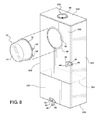
- FIG. 8 is a perspective view of another aspect of a watthour meter socket with a sealed access sub-enclosure
- FIG. 9 is a front elevational view of the socket shown in FIG. 1 , including current transformers.
- FIGS. 1-8 there is depicted a watthour meter socket 10 suited for wall-mounting and capable of removably receiving a watthour meter socket 12 used to measure electric power consumed at a building or residential site.
- the enclosure or housing of the watthour meter 12 may be formed of multiple separate housings which are joined together along two opposed side walls or matching side, top and/or bottom walls of the two housings with the two housings joined by fasteners, welding or other joining means into a unitary one-piece structure capable of being installed as a single unit.
- the watthour meter 12 may be a conventional electromechanical watthour meter or an electronic watthour meter.
- the watthour meter 12 includes a dome or housing 14 , a radially outward extending, circumferential mounting flange of a base mounting flange 16 and a plurality of blade terminals 18 , with only two blade terminals 18 shown in FIG. 1 by way of example, for single phase or three-phase electrical service
- the watthour meter socket 10 includes a unitary housing 20 formed of a top wall 22 , opposed side walls 24 and 26 , a bottom wall 28 opposed from the top wall 22 , and a rear wall or back pan 30 as shown in FIGS. 1-3 .
- the top wall 22 , the rear wall 30 , the side walls 24 and 26 , and the bottom wall 28 may be formed of a single piece of metal which is bent to form the top wall 22 , the side walls 24 and 26 and the bottom wall 28 generally perpendicular with respect to the rear wall 30 .
- the walls 22 , 24 , 26 , 28 and 30 may be formed of individual flat plates which are joined, such as by welding, along adjoining edges, to form the enclosure or housing 20 .
- the top wall 22 has a depending exterior lip 32 which extends between upper ends of the side walls 24 and 26 .
- First and second door or covers 34 and 36 respectively, each have an offset upper edge for insertion behind the lip 32 . This enables the first and second doors 34 and 36 , once the offset flanges at the upper edges of each door 34 and 36 is inserted behind the lip 32 , to be pivoted toward or away from the adjacent side walls 24 and 26 to closed or opened positions relative to the entire housing 20 .
- the closed position of the first and second doors 34 and 36 on the housing 20 is shown in FIG. 1 .
- each clip 42 is pivotally attached to a bottom edge of each of the first and second doors 34 and 36 .
- the free end of each clip 42 has an aperture 44 which is suited for receiving a wire or plastic padlock seal member for tamper indication.
- the free end of each clip 42 is pivotally movable into and out of the respective apertures 40 and the clips 38 .
- a hub opening with hub closure plate 50 is mounted on the top wall 22 .
- the bottom wall 28 of the housing 20 includes a plurality of knockouts to allow the passage of electrical conductors, such as electrical power distribution load conductors connectable to a building electrical power distribution network, to be inserted.
- electrical conductors such as electrical power distribution load conductors connectable to a building electrical power distribution network
- a plurality, such as four one inch diameter knockouts 52 are formed in the bottom wall 28 .
- Additional knockouts 54 may also be formed in the bottom wall 28 .
- one or more optional knockouts 56 may be formed in the rear wall 30 as seen in FIG. 2 .
- the second door 36 has a raised lip 60 surrounding an aperture 62 to form a ringless-style mount through which an end portion of the dome or housing 14 of the watthour meter 12 projects when the watthour meter 12 is mounted in the socket 10 .
- a barrier or interior wall 64 is mounted within the interior of the socket housing 20 .
- the barrier 64 which may be formed of the same material as the housing 20 , such as a powdered coated metal or galvanized metal, extends substantially completely between the top wall 22 and the bottom wall 28 intermediate the side walls 24 and 26 provided arc flash protection.
- the barrier 64 extends substantially the entire depth of the side walls 24 and 26 between the rear wall 30 and the front edges 25 and 27 of the side walls 24 and 26 , respectively.
- the exterior edge of the wall 64 may optionally include a perpendicularly oriented flange to form a seat for the opposed inner edges of the first and second doors 24 and 26 .
- first and second electrically isolated, independently accessible, compartments 70 and 72 cooperate to define first and second electrically isolated, independently accessible, compartments 70 and 72 , respectively, within the housing 20 .
- the first compartment 70 is accessible only through the first access control components or door 34 .
- the second compartment 72 is accessible only through the second access control component door 36 .
- the first compartment 70 defines a first higher voltage compartment for high voltage equipment.
- the first compartment 70 is configured for receiving 480V/440V (600V in Canada) electrical equipment and/or connections.
- the higher voltage equipment are those electrical components, connections or equipment which under the appropriate electrical codes require the use of personal protective equipment (PPE).
- PPE personal protective equipment
- the use of such personal protective equipment is typically associated with the exposure to 480V/440V US or 600V Canada or higher voltages on electrical equipment, connections or components.
- the second compartment 72 defines a second lower voltage compartment suitable for receiving lower voltage equipment, such as a watthour meter components, including a meter base, watthour meter test switches, etc.
- the second compartment 72 is configured for 120V/110V equipment.
- the second compartment 72 receives a removable block bridge 80 which is mounted to the rear wall 30 by a plurality of fasteners.
- the block bridge 80 has a pair of end mounting flanges which receive the fasteners and a raised central portion 82 which receives a multi-terminal block assembly 84 .
- the block 84 is adapted for plug-in connection with the blade terminals 18 of a watthour meter 12 .
- the block 84 includes an insulated housing 86 having individual slots for receiving a plurality of jaw contacts, all denoted by reference number 88 .
- Each jaw contact 88 is fixedly mounted on the housing 86 and has a terminal end for connection to a conductor 100 extending between the block 84 and 88 the test switch assembly 101 .
- jaw contacts 88 may be provided depending upon whether or not the meter socket 10 is for single or three phase electrical power service. Potential contacts 88 also be mounted in the housing 86 and connected by conductors 100 to selected test switches 101 .
- side mounting guards may be provided adjacent opposite side ends of the housing 86 to act as a centering guide for a watthour meter 12 during insertion of the watthour meter socket 12 into the block 84 .
- the block assembly 84 includes eight terminal and eight individual jaws 88 which respectively receive the blade terminals 18 of the watthour meter 12 in a plug-in connection. Seven small potential/KYZ (pulse output) jaws 89 may also be provided in the block 84 .
- block 84 may be replaced by a bottom feed to socket-type adapter, such as an Ekstrom Industries, Inc., 2100 Series Adapter, which similarly receives a plug-in watthour meter 12 .
- socket-type adapter such as an Ekstrom Industries, Inc., 2100 Series Adapter, which similarly receives a plug-in watthour meter 12 .
- the 480 volt electrical power line conductors pass through the knockouts 52 and 54 in the bottom wall 28 of the housing 20 .
- the lower 120 volt electrical power line distribution conductors pass through the knockouts 52 and 54 in the second compartment portion of the bottom wall 28 . Due to the barrier 64 , the higher 480 volt service is confined to the first compartment 70 ; while the lower 120 volt power is confined to the second compartment 72 .
- the higher 480 volt power in the first compartment 70 is electrically isolated from the second compartment 72 .
- Voltage conversion or transformation means are mountable in the first compartment 70 to convert the 480 volt incoming electric power to the lower 120 volt power used by the watthour meter 12 in the second compartment 72 .
- the conductors 100 may be pre-connected between the terminals of the meter block 84 and the terminals on the meter switches 101 .
- the output terminals on the meter switches 101 are connected by a harness or a plurality of conductors denoted by reference number 102 .
- the harness or conductors 102 pass through an opening 104 , which may have a grommet mounted therein for wire protection, to the first compartment 70 wherein the individual conductors of the harness 102 are connected to the voltage conversion means.
- the watthour meter socket 10 may be manufactured and sold in the configuration shown in FIG. 2 without any voltage conversion means mounted in the first compartment 70 .
- the voltage conversion means is then added by the end user utility or utility contractor prior to or at the use site where the watthour meter socket 10 is to be installed.
- the voltage conversion means may be pre-mounted in the first compartment 70 and pre-wired to the harness 102 thereby enabling the watthour meter 12 to be simply installed in the socket 10 at the use site without requiring extensive on-site installation except for connection of the electric power line and load conductors as described above.
- a mounting plate 110 is fixed by fasteners to the portion of the rear wall 30 located in the first compartment 70 .
- the mounting plate 110 may have pre-formed mounting apertures 112 located at mounting positions for receiving individual voltage transformers 114 and 116 , shown in FIG. 4 , each of which converts high voltage service low voltage service, for example 480V to 120V.
- the voltage transformers 114 and 116 may be connected to the conductors of the harness 102 at the socket adapter manufacturing facility, or later during the meter installation process.
- the voltage conversion means includes a 4:1 ratio VT pack sold by Two-Sockets-Two Meters, Inc., of South Dakota.
- the VT pack 118 includes a plurality of transformer-rated 480V/120V transformers. The transformers are pre-wired to a Molex connector.
- a Molex connection or plug 120 shown in FIGS. 2 and 5 , 15 coupled to one end of the conductors of the wiring harness 102 .
- Other conductors from the VT pack 118 are coupled to a terminal block 122 mounted on the rear wall 30 within the first compartment 70 of the socket adapter 10 .
- the watthour meter socket 10 having the individual voltage transformers 114 and 116 shown in FIG. 4 or the VT pack 118 shown in FIG. 5 mounted and connected to the wiring harness 102 is mounted on a suitable surface at the electric power use site.
- the first cover or door 34 is pivotally coupled to the lip 32 on the socket adapter housing 20 and pivoted to a closed position enabling one end of the lock 42 to be pivoted into the aperture 40 in the clip 38 and sealed by a wire or padlock seal. This completely encloses, contains and isolates the higher 480 volt electric power within the first compartment 70 of the watthour meter socket housing 20 from the second compartment 72 .
- the watthour meter 12 is then inserted into the meter base 84 and the second cover 36 pivotally attached at one end to the lip 32 of the housing 20 and moved to a closed position.
- the lock 44 is then pivoted to the closed position within the aperture 40 of the clip 38 and sealed by a wire or padlock seal, not shown. This completes the initial installation of the watthour meter 12 and the watthour meter socket 10 .
- the electric utility person need only remove any existing padlock or wire seal and unlatch the lock member 42 and then pivot and remove the second door 36 to expose the second compartment 72 .
- the watthour meter 12 can then be removed through use of the meter test switches while maintaining electrical power service to the use site until a new watthour meter 12 is installed in the meter block 84 . All of the work involved with the watthour meter 12 in the second compartment 70 is at the lower 120 volt level which does not require personal protection equipment for the electric utility personnel. This simplifies and expedites the meter replacement process.
- the enclosure 110 includes a housing 20 and internal structure, including the interior barrier 64 which is substantially the same as the enclosure 10 described above and shown in FIGS. 1-5 .
- the separate covers or doors 34 and 36 of the enclosure 10 over the first and second sub-enclosure compartments 70 and 72 are replaced by a single large cover or door 112 which extends substantially completely across the open fronts of each sub enclosure or compartments 70 and 72 between the top and bottom walls 22 and 28 and the opposed side walls 24 and 26 of the housing 20 .
- the single door 112 may be hingedly connected to the housing 20 by means of the slide in lip and edge 32 as described previously for the socket 10 .
- the single door 112 still includes the opening 62 for extension of the dome 14 of the watthour meter 12 through the door 112 when the watthour or utility meter 12 is mounted to the socket within the housing 20 .
- At least one clip 38 and lock member 42 are provided on the enclosure 20 and the door 112 for releasibly locking the door 112 to the housing 20 .
- the high voltage or high electric power rated equipment within the first sub-enclosure or compartment 70 requiring the use of personal protective equipment by the utility service person when the service person is exposed to the high voltage equipment, connections or components, is sealed from exposure by a sealed access means 114 , such as an interior cover or panel 116 .
- the interior panel 116 completely covers the interior opening of the first sub-compartment 70 between the sidewall 24 , the interior barrier 64 , the top wall 22 and the bottom wall 28 .
- the panel 116 may be movably mounted within the housing 20 behind the door 112 by a slide in connection similar to that of the door 112 to the housing 20 , a hinged connection 118 shown by exampled in FIG. 6 , a removable screw-in mount, etc.
- the high voltage electrical components housed within the first sub compartment or sub-enclosure 70 are still covered and blocked from exposure by the panel interior 116 .
- This allows the utility service person to be able to open the enclosure 20 by pivotal movement and/or removal of the door 112 to service the low voltage, volt equipment within the second sub enclosure or compartment 72 , including the installation or removal of the watthour meter 12 without having to don personal protective equipment since the high voltage equipment in the sub-enclosure 70 is covered from access, exposure, inadvertent contact, etc., by the panel 116 .
- the panel 116 can be moved to an opened position or removed from the housing 20 after the utility person dons the required personal protective equipment.
- the enclosure 320 is elongated in a vertical normal mounting direction.
- the internal barrier 364 is oriented generally horizontally between the sidewalls 24 and 26 and extends completely between the sidewalls 324 and 326 and from the rear wall 330 to a front edge 327 of the side walls 324 and 326 .
- Two doors 334 and 336 are mounted over respective sub-compartments in a vertical side-by-side orientation.
- the clips 38 and lock members 42 are mounted on the enclosure 320 and on each door 334 and 336 in an appropriate location for easy access.
- doors 334 and 336 in the configuration shown in FIG. 8 may be replaced by a single large door, such as door 112 shown in FIG. 6 , with a separate interior cover or panel, similar to panel 114 , disposed over the lower sub-compartment which receives the high voltage components.
- the position of the high voltage components, such as the transformers 114 , and the meter socket 84 in the horizontal side-by-side configuration shown in FIGS. 1-6 and in the vertical side-by-side configuration of FIG. 8 may be reversed.
- FIG. 7 there is depicted another aspect of an electric power service device having a sealed access sub-enclosure or compartment portion which can contain high voltage equipment or components in a manner which enables the utility person to not have to don personal protective equipment when opening the housing to service the low voltage equipment mounted in the front portion of the housing as described hereafter.
- a utility meter socket 210 includes a housing 220 formed of joined, bent or otherwise fastened together top wall 222 , opposed generally parallel sidewalls 224 and 226 , a bottom wall 228 and a rear or back wall 230 , all of which define an open front edge 232 .
- a cover not shown, but similar to one of the covers 34 and 36 shown in FIG. 1 may be removably or hingedly coupled to the housing 220 by means of the interconnecting flange on the cover and a lip 234 along the front edge of the top wall 222 of the housing 220 .
- High voltage components or electrical equipment shown by way of example only, as a single 480V voltage transformer 114 , are mounted on the backwall 230 or in the sub plate which is attached to the backwall 230 .
- the high voltage components 114 are connected to high voltage utility line conductors, not shown, which enter the housing 220 through one or more hubs 236 .
- a sealed access means or member 240 is shown by way of example only as a single plate or panel 242 .
- the panel 242 extends substantially completely between the inner surfaces of the top wall 220 and the opposed bottom wall 228 , and between inner surfaces of the opposed side walls 224 and 226 to divide the housing 220 into a first sub enclosure or compartment 250 located in front of the panel 242 and a second rear located compartment or sub enclosure 252 located between the rear surface of the panel 242 and the rear wall 230 of the housing 220 .
- the panel 242 completely covers and prevents contact with and exposure to the high voltage components, such as the voltage transformer 114 , mounted in the rear compartment 252 .
- the sealed access means 240 such as the panel 242 , is movably mounted within the housing 220 by slide in, hinged, threaded fasteners, or other connections which enable the panel 242 to be mounted in the position shown in FIG. 7 in which the panel 242 divides the interior of the housing 220 into the separately accessible first or front compartment 250 and the second or rear compartment 252 .
- the panel 242 is illustrated as being coupled by a hinge 254 to the sidewall 224 of the housing 220 .
- a latch or handle may be formed in the panel 242 to facilitate a pivotal movement of the panel 242 about the hinge 254 between the closed, sealed access position shown in FIG.
- the voltage transformers 114 and current transformers, 115 shown in FIG. 9 transform the high voltage in the rear compartment 252 to a lower 120 VAC.
- Conductors 260 extending from the lower voltage terminals of the high voltage equipment pass through an aperture 262 in the panel 242 to a meter socket 264 or indirectly to the meter socket 264 through test switches 266 a described in the previous aspects of the meter socket.
- a rubber grommet 268 may be mounted in the aperture 262 .
Abstract
Description
Claims (8)
Priority Applications (2)
| Application Number | Priority Date | Filing Date | Title |
|---|---|---|---|
| US12/276,891 US8547686B2 (en) | 2008-11-24 | 2008-11-24 | Watthour meter socket with secured access high voltage section |
| CA2645391A CA2645391A1 (en) | 2008-11-24 | 2008-11-27 | Watthour meter socket with secured access high voltage section |
Applications Claiming Priority (1)
| Application Number | Priority Date | Filing Date | Title |
|---|---|---|---|
| US12/276,891 US8547686B2 (en) | 2008-11-24 | 2008-11-24 | Watthour meter socket with secured access high voltage section |
Publications (2)
| Publication Number | Publication Date |
|---|---|
| US20100128418A1 US20100128418A1 (en) | 2010-05-27 |
| US8547686B2 true US8547686B2 (en) | 2013-10-01 |
Family
ID=42196042
Family Applications (1)
| Application Number | Title | Priority Date | Filing Date |
|---|---|---|---|
| US12/276,891 Active US8547686B2 (en) | 2008-11-24 | 2008-11-24 | Watthour meter socket with secured access high voltage section |
Country Status (2)
| Country | Link |
|---|---|
| US (1) | US8547686B2 (en) |
| CA (1) | CA2645391A1 (en) |
Cited By (7)
| Publication number | Priority date | Publication date | Assignee | Title |
|---|---|---|---|---|
| US20160072260A1 (en) * | 2013-05-23 | 2016-03-10 | Access Innovators, LLC | Electrical Power Distribution and Conversion Assembly Suitable for Portable Work Platforms |
| US10020627B1 (en) | 2017-01-09 | 2018-07-10 | E.J. Brooks Company | Watthour meter block with safety shield |
| US20180196093A1 (en) * | 2017-01-09 | 2018-07-12 | E.J. Brooks Company D.B.A. Brooks Utility Products Group | Watthour meter block with safety shield |
| USD873689S1 (en) | 2017-01-09 | 2020-01-28 | E.J. Brooks Company | Watthour meter block with safety shield |
| US20220149600A1 (en) * | 2020-11-09 | 2022-05-12 | City of Dubuque | Multi-function cabinet |
| EP4027072A1 (en) * | 2020-12-29 | 2022-07-13 | Trane International Inc. | Layered control panel design to provide separation of high/low voltage |
| US11493545B2 (en) * | 2018-11-10 | 2022-11-08 | Setra Systems, Inc. | Measurement device and method of its operation |
Families Citing this family (13)
| Publication number | Priority date | Publication date | Assignee | Title |
|---|---|---|---|---|
| US8107226B2 (en) * | 2009-07-24 | 2012-01-31 | Connecticut Electric, Inc. | Transfer switch with easily removable weatherproof door and hood |
| US8369068B2 (en) * | 2010-05-21 | 2013-02-05 | Generac Power Systems, Inc. | Transfer switch enclosure |
| US9099845B2 (en) | 2012-04-23 | 2015-08-04 | Thomas & Betts International, Inc. | Meter socket with current bypass |
| WO2015006553A1 (en) * | 2013-07-11 | 2015-01-15 | Cintas Corporation | Contact voltage detection system and method |
| US9772347B2 (en) | 2013-08-28 | 2017-09-26 | San Diego Gas & Electric Company | Interconnection meter socket adapters |
| US9995768B2 (en) | 2013-08-28 | 2018-06-12 | San Diego Gas & Electric | Interconnection meter socket adapters |
| US10132838B2 (en) * | 2013-08-28 | 2018-11-20 | San Diego Gas & Electric Company | Managing power source interaction through an interconnect socket adapter configured with an energy storage source/sink |
| US10089641B2 (en) | 2013-08-28 | 2018-10-02 | San Diego Gas & Electric Company | Interconnect socket adapter for adapting one or more power sources and power sinks |
| US9904308B2 (en) | 2013-08-28 | 2018-02-27 | San Diego Gas & Electric Company | Managing power source interaction through an interconnect socket adapter configured with an electric vehicle sink |
| CA2832237A1 (en) | 2013-11-07 | 2015-05-07 | Circuitmeter Inc. | Isolation interface for an electricity meter and electricity metering system |
| US11415608B2 (en) * | 2019-09-27 | 2022-08-16 | TSTM, Inc. | Transformer and socket assembly for power meter installations |
| CN113341184B (en) * | 2021-06-08 | 2022-05-24 | 深圳市先行电气技术有限公司 | Intelligent electric meter with overload protection device |
| CN115939968B (en) * | 2023-02-15 | 2023-05-23 | 国网山东省电力公司临朐县供电公司 | Power distribution box |
Citations (57)
| Publication number | Priority date | Publication date | Assignee | Title |
|---|---|---|---|---|
| US1898634A (en) * | 1929-01-28 | 1933-02-21 | M J Lewis Products Company | Service box |
| US2013525A (en) * | 1934-04-18 | 1935-09-03 | Gen Electric | Electrical switch gear |
| US2182603A (en) * | 1938-04-08 | 1939-12-05 | Walker Electrical Company | Meter box |
| US3025432A (en) * | 1959-01-16 | 1962-03-13 | Gen Electric | Factory assembled electrical service package |
| US3397346A (en) * | 1965-09-08 | 1968-08-13 | Clifford E. Sloop | Meter box and liner |
| US3744010A (en) | 1970-03-05 | 1973-07-03 | Ite Imperial Corp | Socket for multiple meter panel |
| US3906295A (en) * | 1974-02-05 | 1975-09-16 | Wallace David Tessmer | Service pedestal for electrical control means including a meter |
| US4025825A (en) | 1975-07-24 | 1977-05-24 | Delworth Shrader | Meter power distribution apparatus for mobile homes with a detachable front panel for power outlet fittings |
| US4226102A (en) * | 1979-08-22 | 1980-10-07 | Norman S. Blodgett | Meter lock |
| US4249227A (en) * | 1976-12-14 | 1981-02-03 | Tokyo Shibaura Electric Co., Ltd. | Enclosed switchboard having instruments needed for regular inspection and operation mounted on a middle level door |
| US4404521A (en) | 1980-08-18 | 1983-09-13 | Fennell Robert B | Pilfer proofing system and method for electric utility meter box |
| US4888448A (en) * | 1989-06-16 | 1989-12-19 | Moerman Paul G | Temporary electrical power pedestal |
| US4998612A (en) | 1989-04-11 | 1991-03-12 | Idx, Inc. | Meter box with hidden hinged door |
| US5033973A (en) * | 1990-04-23 | 1991-07-23 | Ekstrom Industries, Inc. | Service disconnect and meter storage adapter |
| US5041001A (en) * | 1990-11-26 | 1991-08-20 | Innovative Building Products | Watt-hour meter plug |
| US5097383A (en) * | 1989-04-24 | 1992-03-17 | Heard Gregory L | Porta-temp |
| US5121824A (en) | 1989-04-11 | 1992-06-16 | Idx, Inc. | Meter box with removable hinged door |
| US5145403A (en) * | 1991-06-26 | 1992-09-08 | Meter Devices Company, Inc. | Safety cover for meter socket |
| US5216802A (en) * | 1989-04-24 | 1993-06-08 | Cole Michael P | Method of using a convertible metered power system to convert between temporary and permanent metered electric service |
| JPH06253422A (en) * | 1993-03-03 | 1994-09-09 | Chiyuuritsu Denki Kk | High-voltage receiving and distributing device |
| US5404266A (en) * | 1994-01-31 | 1995-04-04 | General Electric Company | Temporary power center for construction site |
| US5418683A (en) * | 1994-02-07 | 1995-05-23 | General Electric Company | Temporary power center for construction site |
| US5546269A (en) * | 1994-07-13 | 1996-08-13 | Ekstrom Industries, Inc. | Metered electrical service tap |
| US5572396A (en) * | 1995-04-21 | 1996-11-05 | Ekstrom Industries, Inc. | Electric service safety disconnect apparatus with overvoltage and overcurrent protection |
| US5638256A (en) * | 1995-05-30 | 1997-06-10 | Square D. Company | Combination service entrance device for temporary and permanent use |
| US5774328A (en) * | 1996-04-15 | 1998-06-30 | General Electric Company | Register enclosure for use with a utility meter |
| US5834932A (en) * | 1997-03-17 | 1998-11-10 | May; Gregory R. | Watthour meter system |
| US5870276A (en) * | 1995-05-31 | 1999-02-09 | Square D Company | Electrical power distribution device with elevated removable load center |
| US5997347A (en) * | 1996-06-03 | 1999-12-07 | Ekstrom Industries, Inc. | Watthour meter socket adapter with snap-on jaw contacts |
| US6046904A (en) * | 1999-03-11 | 2000-04-04 | Eaton Corporation | Electrical equipment cabinet having barrier with integral drip channel |
| US6254437B1 (en) | 1999-02-02 | 2001-07-03 | Thomas & Betts International | Utility metering transocket |
| US6266233B1 (en) * | 2000-03-21 | 2001-07-24 | Electrical Materials Co. | Temporary power center for underground residential distribution system |
| US6384350B1 (en) * | 1999-08-02 | 2002-05-07 | Meter Devices Company | Meter test switch |
| US6421229B1 (en) * | 2000-12-21 | 2002-07-16 | Eaton Corporation | Combination meter/breaker panel enclosure with rain gutter and security system |
| WO2002088642A1 (en) * | 2001-05-02 | 2002-11-07 | Invensys Metering Systems/North America Inc. | Add-on module for utility meters |
| US6504268B1 (en) * | 2000-10-19 | 2003-01-07 | Reliance Controls Corporation | Transfer switch with selectively configurable cover structure with power input and meter capability |
| US6545374B1 (en) * | 1999-09-27 | 2003-04-08 | Michael E. Allenbach | Power transfer device installable in a power meter receptacle |
| US6589072B2 (en) * | 1999-06-07 | 2003-07-08 | Ekstrom Industries, Inc. | Watthour meter socket adapter with auxiliary component mounts |
| US6605937B2 (en) * | 2001-06-01 | 2003-08-12 | General Electric Company | Modular meter with base barrier |
| US6687627B1 (en) * | 1999-08-09 | 2004-02-03 | Power Measurement Ltd. | Electric charge storage apparatus and method for an intelligent electronic device |
| US6773652B2 (en) * | 2002-10-02 | 2004-08-10 | Elster Electricity, Llc | Process for the manufacture of a cover system for an electrical-energy meter |
| US20040165340A1 (en) * | 2002-12-09 | 2004-08-26 | Wilfong M Scott | Preconstruction multiple utility meter pedestal and method of installation |
| US6798191B1 (en) * | 1999-08-09 | 2004-09-28 | Power Measurement Ltd. | Revenue meter with a graphic user interface being operative to display scalable objects |
| WO2005001994A2 (en) * | 2003-06-06 | 2005-01-06 | Alpha Technologies, Inc. | Connection systems and methods for utility meters |
| EP1538449A2 (en) * | 1999-01-27 | 2005-06-08 | Elster Electricity, LLC | Voltage disconnect link for energy meter |
| US6940711B2 (en) * | 1999-01-27 | 2005-09-06 | Elster Electricity, Llc | Advanced instrument packaging for electronic energy meter |
| US6956733B2 (en) * | 2002-09-30 | 2005-10-18 | Basic Resources Inc. | Device and method for providing electric service |
| US20050239325A1 (en) | 2004-04-26 | 2005-10-27 | Meter Devices Company, Inc. | Modular watthour meter socket and test switch |
| US20050270016A1 (en) * | 2004-06-02 | 2005-12-08 | Rajaiah Karanam | Electronic residential electricity meter |
| US20060181838A1 (en) * | 2005-02-01 | 2006-08-17 | The Southern Company | Meter package system |
| US20060265853A1 (en) * | 2005-05-10 | 2006-11-30 | Povolny Michael J | Apparatus and method for l-shaped cabinet |
| US7199572B1 (en) | 2005-03-01 | 2007-04-03 | Greg May | Method and system for improving the operational safety, reliability, and functionality of electrical power consumption monitoring devices |
| US7239502B1 (en) * | 2006-01-20 | 2007-07-03 | Eaton Corporation | Meter center and multi-phase multiple meter socket assembly therefor |
| US7286339B2 (en) * | 2004-03-11 | 2007-10-23 | Baca William C | Combination service entrance apparatus for temporary and permanent use |
| US7397652B2 (en) * | 2002-09-30 | 2008-07-08 | Basic Resources, Inc. | Device and method for providing electric service |
| US7540766B2 (en) * | 2006-06-14 | 2009-06-02 | Itron, Inc. | Printed circuit board connector for utility meters |
| US20090267466A1 (en) * | 2008-04-28 | 2009-10-29 | Meter Devices Company, Inc. | Primary enclosure for electric power meters |
Family Cites Families (1)
| Publication number | Priority date | Publication date | Assignee | Title |
|---|---|---|---|---|
| JP2004111796A (en) * | 2002-09-20 | 2004-04-08 | Hitachi Ltd | Semiconductor device |
-
2008
- 2008-11-24 US US12/276,891 patent/US8547686B2/en active Active
- 2008-11-27 CA CA2645391A patent/CA2645391A1/en not_active Abandoned
Patent Citations (59)
| Publication number | Priority date | Publication date | Assignee | Title |
|---|---|---|---|---|
| US1898634A (en) * | 1929-01-28 | 1933-02-21 | M J Lewis Products Company | Service box |
| US2013525A (en) * | 1934-04-18 | 1935-09-03 | Gen Electric | Electrical switch gear |
| US2182603A (en) * | 1938-04-08 | 1939-12-05 | Walker Electrical Company | Meter box |
| US3025432A (en) * | 1959-01-16 | 1962-03-13 | Gen Electric | Factory assembled electrical service package |
| US3397346A (en) * | 1965-09-08 | 1968-08-13 | Clifford E. Sloop | Meter box and liner |
| US3744010A (en) | 1970-03-05 | 1973-07-03 | Ite Imperial Corp | Socket for multiple meter panel |
| US3906295A (en) * | 1974-02-05 | 1975-09-16 | Wallace David Tessmer | Service pedestal for electrical control means including a meter |
| US4025825A (en) | 1975-07-24 | 1977-05-24 | Delworth Shrader | Meter power distribution apparatus for mobile homes with a detachable front panel for power outlet fittings |
| US4249227A (en) * | 1976-12-14 | 1981-02-03 | Tokyo Shibaura Electric Co., Ltd. | Enclosed switchboard having instruments needed for regular inspection and operation mounted on a middle level door |
| US4226102A (en) * | 1979-08-22 | 1980-10-07 | Norman S. Blodgett | Meter lock |
| US4404521A (en) | 1980-08-18 | 1983-09-13 | Fennell Robert B | Pilfer proofing system and method for electric utility meter box |
| US4998612A (en) | 1989-04-11 | 1991-03-12 | Idx, Inc. | Meter box with hidden hinged door |
| US5121824A (en) | 1989-04-11 | 1992-06-16 | Idx, Inc. | Meter box with removable hinged door |
| US5216802A (en) * | 1989-04-24 | 1993-06-08 | Cole Michael P | Method of using a convertible metered power system to convert between temporary and permanent metered electric service |
| US5097383A (en) * | 1989-04-24 | 1992-03-17 | Heard Gregory L | Porta-temp |
| US4888448A (en) * | 1989-06-16 | 1989-12-19 | Moerman Paul G | Temporary electrical power pedestal |
| US5033973A (en) * | 1990-04-23 | 1991-07-23 | Ekstrom Industries, Inc. | Service disconnect and meter storage adapter |
| US5041001A (en) * | 1990-11-26 | 1991-08-20 | Innovative Building Products | Watt-hour meter plug |
| US5145403A (en) * | 1991-06-26 | 1992-09-08 | Meter Devices Company, Inc. | Safety cover for meter socket |
| JPH06253422A (en) * | 1993-03-03 | 1994-09-09 | Chiyuuritsu Denki Kk | High-voltage receiving and distributing device |
| US5404266A (en) * | 1994-01-31 | 1995-04-04 | General Electric Company | Temporary power center for construction site |
| US5418683A (en) * | 1994-02-07 | 1995-05-23 | General Electric Company | Temporary power center for construction site |
| US5546269A (en) * | 1994-07-13 | 1996-08-13 | Ekstrom Industries, Inc. | Metered electrical service tap |
| US5572396A (en) * | 1995-04-21 | 1996-11-05 | Ekstrom Industries, Inc. | Electric service safety disconnect apparatus with overvoltage and overcurrent protection |
| US5638256A (en) * | 1995-05-30 | 1997-06-10 | Square D. Company | Combination service entrance device for temporary and permanent use |
| US5870276A (en) * | 1995-05-31 | 1999-02-09 | Square D Company | Electrical power distribution device with elevated removable load center |
| US5774328A (en) * | 1996-04-15 | 1998-06-30 | General Electric Company | Register enclosure for use with a utility meter |
| US5997347A (en) * | 1996-06-03 | 1999-12-07 | Ekstrom Industries, Inc. | Watthour meter socket adapter with snap-on jaw contacts |
| US5834932A (en) * | 1997-03-17 | 1998-11-10 | May; Gregory R. | Watthour meter system |
| US6940711B2 (en) * | 1999-01-27 | 2005-09-06 | Elster Electricity, Llc | Advanced instrument packaging for electronic energy meter |
| EP1538449A2 (en) * | 1999-01-27 | 2005-06-08 | Elster Electricity, LLC | Voltage disconnect link for energy meter |
| US6254437B1 (en) | 1999-02-02 | 2001-07-03 | Thomas & Betts International | Utility metering transocket |
| US6046904A (en) * | 1999-03-11 | 2000-04-04 | Eaton Corporation | Electrical equipment cabinet having barrier with integral drip channel |
| US6589072B2 (en) * | 1999-06-07 | 2003-07-08 | Ekstrom Industries, Inc. | Watthour meter socket adapter with auxiliary component mounts |
| US6384350B1 (en) * | 1999-08-02 | 2002-05-07 | Meter Devices Company | Meter test switch |
| US6687627B1 (en) * | 1999-08-09 | 2004-02-03 | Power Measurement Ltd. | Electric charge storage apparatus and method for an intelligent electronic device |
| US6798191B1 (en) * | 1999-08-09 | 2004-09-28 | Power Measurement Ltd. | Revenue meter with a graphic user interface being operative to display scalable objects |
| US6545374B1 (en) * | 1999-09-27 | 2003-04-08 | Michael E. Allenbach | Power transfer device installable in a power meter receptacle |
| US6266233B1 (en) * | 2000-03-21 | 2001-07-24 | Electrical Materials Co. | Temporary power center for underground residential distribution system |
| US6504268B1 (en) * | 2000-10-19 | 2003-01-07 | Reliance Controls Corporation | Transfer switch with selectively configurable cover structure with power input and meter capability |
| US6421229B1 (en) * | 2000-12-21 | 2002-07-16 | Eaton Corporation | Combination meter/breaker panel enclosure with rain gutter and security system |
| WO2002088642A1 (en) * | 2001-05-02 | 2002-11-07 | Invensys Metering Systems/North America Inc. | Add-on module for utility meters |
| US6605937B2 (en) * | 2001-06-01 | 2003-08-12 | General Electric Company | Modular meter with base barrier |
| US6956733B2 (en) * | 2002-09-30 | 2005-10-18 | Basic Resources Inc. | Device and method for providing electric service |
| US7397652B2 (en) * | 2002-09-30 | 2008-07-08 | Basic Resources, Inc. | Device and method for providing electric service |
| US6773652B2 (en) * | 2002-10-02 | 2004-08-10 | Elster Electricity, Llc | Process for the manufacture of a cover system for an electrical-energy meter |
| US20040165340A1 (en) * | 2002-12-09 | 2004-08-26 | Wilfong M Scott | Preconstruction multiple utility meter pedestal and method of installation |
| WO2005001994A2 (en) * | 2003-06-06 | 2005-01-06 | Alpha Technologies, Inc. | Connection systems and methods for utility meters |
| US7286339B2 (en) * | 2004-03-11 | 2007-10-23 | Baca William C | Combination service entrance apparatus for temporary and permanent use |
| US20050239325A1 (en) | 2004-04-26 | 2005-10-27 | Meter Devices Company, Inc. | Modular watthour meter socket and test switch |
| US7479029B2 (en) * | 2004-04-26 | 2009-01-20 | Meter Devices Company, Inc. | Modular watthour meter socket and test switch |
| US20050270016A1 (en) * | 2004-06-02 | 2005-12-08 | Rajaiah Karanam | Electronic residential electricity meter |
| US7265532B2 (en) * | 2004-06-02 | 2007-09-04 | General Electric Company | Electronic electricity meter and method of assembly |
| US20060181838A1 (en) * | 2005-02-01 | 2006-08-17 | The Southern Company | Meter package system |
| US7199572B1 (en) | 2005-03-01 | 2007-04-03 | Greg May | Method and system for improving the operational safety, reliability, and functionality of electrical power consumption monitoring devices |
| US20060265853A1 (en) * | 2005-05-10 | 2006-11-30 | Povolny Michael J | Apparatus and method for l-shaped cabinet |
| US7239502B1 (en) * | 2006-01-20 | 2007-07-03 | Eaton Corporation | Meter center and multi-phase multiple meter socket assembly therefor |
| US7540766B2 (en) * | 2006-06-14 | 2009-06-02 | Itron, Inc. | Printed circuit board connector for utility meters |
| US20090267466A1 (en) * | 2008-04-28 | 2009-10-29 | Meter Devices Company, Inc. | Primary enclosure for electric power meters |
Non-Patent Citations (15)
| Title |
|---|
| Bottom-Fed to Socket-Type Adapters Polyphase Series, 2100 Series, Ekstrom Industries, Inc. 2002. |
| Brooks Utility Products Group, 23847 Industrial Park Drive, Farmington Hills, MI. 48335-2583; Trans Sockets, 2001. |
| Marwell Corporation, PO Box 139, Mentone, CA 92359; Marwell News, Sep. 2002, Auto By-Pass Conversion Adapter. |
| Marwell Corporation, PO Box 3147,San Bernardino, CA 92413; Marwell News, Apr. 1998, Marwell 2200-N with States Test Switch. |
| Meter Devices Company, Inc 3359 Bruening Avenue S.W., Canton, Ohio 44706. Lexan Non-Corrosive Prewired Meter Socket Corrosion Free Protection, 2002. |
| Mini-Transocket; Meter Devices Company; 3359 Bruening Avenue S.W., Canton, OH, 44706; www.meter-devices.com, 2001. |
| Problem Solvers for Utilities, 2008 Edition, Brooks Utility Products Group; p. 3, 2008. |
| Transformer Rated Meter Sockets, Series 3000, Meter Devices Company, Inc., 1998. * |
| Transocket; 200-600 Ampere Instrument Transformers; ABB Inc., Highway 43 North; Pinetops NC 27864; www.abb.com/mediumvoltage, 2003. |
| Transockets; Meter Devices Company; 3359 Bruening Avenue S.W., Canton, OH, 44706; www.meter-devices.com, 2002. |
| Two Sockets Two Meters; http://www.socket-two-me.com/about.php; Aug. 29, 2008; p. 1 of 1. |
| Two Sockets Two Meters; http://www.socket-two-me.com/contact.php Aug. 29, 2008; p. 1 of 1. |
| Two Sockets Two Meters; http://www.socket-two-me.com/productdetail.php; Aug. 29, 2008; p. 1 of 1. |
| Two Sockets Two Meters; http://www.socket-two-me.com/productdetail.php?i=13; Aug. 29, 2008; p. 1 of 1. |
| Two Sockets Two Meters; http://www.socket-two-me.com/why.php; Aug. 29, 2008; p. 1 of 1. |
Cited By (10)
| Publication number | Priority date | Publication date | Assignee | Title |
|---|---|---|---|---|
| US20160072260A1 (en) * | 2013-05-23 | 2016-03-10 | Access Innovators, LLC | Electrical Power Distribution and Conversion Assembly Suitable for Portable Work Platforms |
| US10020627B1 (en) | 2017-01-09 | 2018-07-10 | E.J. Brooks Company | Watthour meter block with safety shield |
| US20180196093A1 (en) * | 2017-01-09 | 2018-07-12 | E.J. Brooks Company D.B.A. Brooks Utility Products Group | Watthour meter block with safety shield |
| USD873689S1 (en) | 2017-01-09 | 2020-01-28 | E.J. Brooks Company | Watthour meter block with safety shield |
| US10620242B2 (en) * | 2017-01-09 | 2020-04-14 | E.J. Brooks Company | Watthour meter block with safety shield |
| US11493545B2 (en) * | 2018-11-10 | 2022-11-08 | Setra Systems, Inc. | Measurement device and method of its operation |
| US20220149600A1 (en) * | 2020-11-09 | 2022-05-12 | City of Dubuque | Multi-function cabinet |
| US11641093B2 (en) * | 2020-11-09 | 2023-05-02 | City of Dubuque | Multi-function cabinet |
| EP4027072A1 (en) * | 2020-12-29 | 2022-07-13 | Trane International Inc. | Layered control panel design to provide separation of high/low voltage |
| US11774132B2 (en) | 2020-12-29 | 2023-10-03 | Trane International Inc. | Layered control panel design to provide separation of high/low voltage |
Also Published As
| Publication number | Publication date |
|---|---|
| CA2645391A1 (en) | 2010-05-24 |
| US20100128418A1 (en) | 2010-05-27 |
Similar Documents
| Publication | Publication Date | Title |
|---|---|---|
| US8547686B2 (en) | Watthour meter socket with secured access high voltage section | |
| US7140702B2 (en) | Medium voltage motor control center arc resistant enclosure | |
| US6663405B1 (en) | Disconnect watthour meter socket adapter | |
| US3585456A (en) | Electric service center for mobile homes and the like | |
| US6512669B1 (en) | Medium voltage motor control center instrument compartment | |
| US9312665B2 (en) | Electrical distribution systems incuding parallel energy source and methods | |
| US6266233B1 (en) | Temporary power center for underground residential distribution system | |
| US9627861B2 (en) | Utility meter bypass systems, methods, and devices | |
| US20140334073A1 (en) | Apparatus for protecting against theft of electricity from distribution transformers | |
| US8027154B2 (en) | Replacement panel board and methods for selecting | |
| US20140265562A1 (en) | Apparatus for protecting against theft of electricity from distribution transformers | |
| US9099845B2 (en) | Meter socket with current bypass | |
| US10813234B2 (en) | Distributed energy generation and consumption monitoring and reporting device with modular communication upgradability and protection domains in hardware | |
| US20030119344A1 (en) | Medium voltage motor control center load discharge device | |
| US11637413B2 (en) | Methods for making an energized parts guard system | |
| US10236665B2 (en) | Insulated electrical switch cabinet cover | |
| US6638116B2 (en) | Medium voltage motor control center springless finger cluster | |
| US1628406A (en) | Service switch and appurtenant protective fitting | |
| JP7364345B2 (en) | Temporary power supply box for switchgear and temporary power supply method | |
| TRANSFER-ENCLOSED | MATERIAL STANDARD | |
| Rajasthan et al. | Government of Rajasthan | |
| CA2897083A1 (en) | Apparatus for protecting against theft of electricity from distribution transformers | |
| RU34810U1 (en) | Accounting and distribution device (3 UR-200) | |
| US20120033352A1 (en) | Motor Control Center Subunit(s) (bucket(s)) with compartmentalized disconnect associated with a distinctly separate load section. | |
| CA2205635C (en) | Watt-hour socket adapter with improved electrical connections |
Legal Events
| Date | Code | Title | Description |
|---|---|---|---|
| AS | Assignment |
Owner name: METER DEVICES COMPANY, INC., OHIO Free format text: ASSIGNMENT OF ASSIGNORS INTEREST;ASSIGNORS:PRUEHS, ALLEN;HANFT, JEFFREY J.;REEL/FRAME:021883/0347 Effective date: 20081120 |
|
| STCF | Information on status: patent grant |
Free format text: PATENTED CASE |
|
| AS | Assignment |
Owner name: WELLS FARGO BANK, NATIONAL ASSOCIATION, CALIFORNIA Free format text: SECURITY INTEREST;ASSIGNOR:E.J. BROOKS COMPANY;REEL/FRAME:034380/0941 Effective date: 20141121 |
|
| AS | Assignment |
Owner name: BANK OF AMERICA, N.A., AS ADMINISTRATIVE AGENT, CA Free format text: PATENT SECURITY AGREEMENT;ASSIGNORS:E.J. BROOKS COMPANY;TELESIS TECHNOLOGIES, INC.;REEL/FRAME:038065/0892 Effective date: 20160311 |
|
| AS | Assignment |
Owner name: E.J. BROOKS COMPANY (AS SUCCESSOR BY MERGER TO EKS Free format text: RELEASE OF PATENT COLLATERAL;ASSIGNOR:WELLS FARGO BANK, NATIONAL ASSOCIATION, AS AGENT;REEL/FRAME:038079/0063 Effective date: 20160311 |
|
| AS | Assignment |
Owner name: EKSTROM INDUSTRIES, INC., MICHIGAN Free format text: MERGER;ASSIGNOR:METER DEVICES COMPANY, INC.;REEL/FRAME:038647/0880 Effective date: 20101231 Owner name: E.J. BROOKS COMPANY, INDIANA Free format text: MERGER;ASSIGNOR:EKSTROM INDUSTRIES, INC.;REEL/FRAME:038648/0261 Effective date: 20121217 |
|
| FPAY | Fee payment |
Year of fee payment: 4 |
|
| AS | Assignment |
Owner name: SUNTRUST BANK, AS ADMINISTRATIVE AGENT, GEORGIA Free format text: PATENT SECURITY AGREEMENT;ASSIGNORS:E.J. BROOKS COMPANY;TELESIS TECHNOLOGIES, INC.;REEL/FRAME:051024/0148 Effective date: 20191114 Owner name: TELESIS TECHNOLOGIES, INC., CALIFORNIA Free format text: TERMINATION AND RELEASE OF SECURITY INTEREST IN PATENTS;ASSIGNOR:BANK OF AMERICA, N.A., AS ADMINISTRATIVE AGENT;REEL/FRAME:051024/0121 Effective date: 20191114 Owner name: E.J. BROOKS COMPANY, CALIFORNIA Free format text: TERMINATION AND RELEASE OF SECURITY INTEREST IN PATENTS;ASSIGNOR:BANK OF AMERICA, N.A., AS ADMINISTRATIVE AGENT;REEL/FRAME:051024/0121 Effective date: 20191114 |
|
| MAFP | Maintenance fee payment |
Free format text: PAYMENT OF MAINTENANCE FEE, 8TH YEAR, LARGE ENTITY (ORIGINAL EVENT CODE: M1552); ENTITY STATUS OF PATENT OWNER: LARGE ENTITY Year of fee payment: 8 |
|
| AS | Assignment |
Owner name: TELESIS TECHNOLOGIES INC., OHIO Free format text: RELEASE BY SECURED PARTY;ASSIGNOR:TRUIST BANK (AS SUCCESSOR-BY-MERGER TO SUNTRUST BANK);REEL/FRAME:060440/0554 Effective date: 20220419 Owner name: E.J. BROOKS COMPANY, GEORGIA Free format text: RELEASE BY SECURED PARTY;ASSIGNOR:TRUIST BANK (AS SUCCESSOR-BY-MERGER TO SUNTRUST BANK);REEL/FRAME:060440/0554 Effective date: 20220419 |
|
| AS | Assignment |
Owner name: CIBC BANK USA, ILLINOIS Free format text: SECURITY INTEREST;ASSIGNORS:TYDENBROOKS, LLC;E.J. BROOKS COMPANY;REEL/FRAME:062389/0962 Effective date: 20221004 |
|
| AS | Assignment |
Owner name: WELLS FARGO BANK, NATIONAL ASSOCIATION, AS ADMINISTRATIVE AGENT, VIRGINIA Free format text: SECURITY INTEREST;ASSIGNOR:TYDENBROOKS LLC;REEL/FRAME:064450/0311 Effective date: 20230721 |
|
| AS | Assignment |
Owner name: EKSTROM INDUSTRIES, INC., MICHIGAN Free format text: MERGER AND CHANGE OF NAME;ASSIGNORS:METER DEVICES COMPANY, INC.;EKSTROM INDUSTRIES, INC.;REEL/FRAME:065331/0933 Effective date: 20101231 Owner name: E.J. BROOKS COMPANY, INDIANA Free format text: MERGER AND CHANGE OF NAME;ASSIGNORS:EKSTROM INDUSTRIES, INC.;E.J. BROOKS COMPANY;REEL/FRAME:065319/0073 Effective date: 20121217 |