US8577184B2 - System and method for super-resolution imaging from a sequence of color filter array (CFA) low-resolution images - Google Patents
System and method for super-resolution imaging from a sequence of color filter array (CFA) low-resolution images Download PDFInfo
- Publication number
- US8577184B2 US8577184B2 US12/968,881 US96888110A US8577184B2 US 8577184 B2 US8577184 B2 US 8577184B2 US 96888110 A US96888110 A US 96888110A US 8577184 B2 US8577184 B2 US 8577184B2
- Authority
- US
- United States
- Prior art keywords
- image
- color
- images
- monochromatic
- frames
- Prior art date
- Legal status (The legal status is an assumption and is not a legal conclusion. Google has not performed a legal analysis and makes no representation as to the accuracy of the status listed.)
- Expired - Fee Related, expires
Links
Images


Classifications
-
- G—PHYSICS
- G06—COMPUTING; CALCULATING OR COUNTING
- G06T—IMAGE DATA PROCESSING OR GENERATION, IN GENERAL
- G06T3/00—Geometric image transformation in the plane of the image
- G06T3/40—Scaling the whole image or part thereof
- G06T3/4053—Super resolution, i.e. output image resolution higher than sensor resolution
- G06T3/4069—Super resolution, i.e. output image resolution higher than sensor resolution by subpixel displacement
Definitions
- This invention relates in general to a method of digital image processing, and more specifically relates to super-resolution image reconstruction.
- subpixel refers to one or more components of a single pixel.
- the components of a single pixel comprise several primary color primaries, which may be three ordered color elements such as blue, green, and red (BGR), or red, green, and blue (RGB), or green, blue, red.
- BGR blue, green, and red
- RGB red, green, and blue
- Some image displays have more than three primaries, further including yellow (RGBY), or white (RGBW), or yellow and cyan (RGBYC).
- Sub-pixels may appear as a single color when viewed directly by the human eye due to spatial integration by the eye. However, the components may be visible under a magnification.
- the colors in the sub-pixels are not visible, but the relative intensity of the components may cause a shift in the apparent position or orientation of a line.
- the resolution at which sub-pixels go unnoticed may depend upon the viewer or the application as the visual processes of humans vary; whereby the colored “fringes” resulting from sub-pixel rendering may cause distraction in some individuals or applications but not others. Methods that account for sub-pixel rendering are generally called subpixel rendering algorithms.
- Image resolution relates to the detail that an image possesses.
- the resolution generally correlates to the area represented by each pixel.
- an image is considered to be more accurate and detailed as the area represented by each pixel is decreased.
- images includes digital images, film images, and/or other types of images.
- sampling refers to the practice of collecting a subset of individual observations intended to yield some knowledge about a subject. “Sampling” includes the act, process, or technique of selecting a representative part of a population or sequence of moving images for the purpose of determining parameters or characteristics of the whole population or moving image sequence. For example, according to the 1949 sampling theorem by C E Shannon, in order to recover a signal function ⁇ (t) precisely, the sampling rate must be done at a rate greater than twice the signal's highest frequency component.
- demosaicing process is a digital image process of reconstructing a full color image from incomplete color samples output from an image sensor or camera overlaid with a color filter array (CFA).
- CCD charge-coupled device
- CMOS complementary metal-oxide semiconductor
- a CFA is an array that is used in front of the image sensors to alternate color filters that samples only one color channel at each pixel location.
- the most popular and common CFA is arranged in mosaic pattern, called the Bayer pattern, as described in U.S. Pat. No. 3,971,065, “Color image array,” July 1976, B. E. Bayer, which is illustrated in FIG. 1 .
- the Bayer pattern For each 2 ⁇ 2 set of pixels, two diagonally opposed pixels have green filters, and the other two pixels have red and blue filters, which is called quincunx sampling pattern.
- a Bayer image can be also seen as a grayscale image as shown in FIG. 28 .
- CFA color filter array
- the resolution of a color image reconstructed from the demosaicing method is equal to the physical resolution of a CCD.
- the resolution of an image sensor can be improved by a digital image processing algorithm: super-resolution image reconstruction.
- Super-resolution image reconstruction generally increases image resolution without necessitating a change in the design of the optics and/or detectors by using a sequence (or a few snapshots) of low-resolution images.
- Super-resolution image reconstruction algorithms effectively de-alias undersampled images to obtain a substantially alias-free or, as identified in the literature, a super-resolved image.
- Super-resolution image reconstruction involves, inter alia, combining information contained in undersampled images to obtain an alias-free (high-resolution) image.
- Super-resolution image reconstruction from multiple snapshots, taken by a detector which has shifted in position, provides far more detail information than any interpolated image from a single snapshot.
- One of these methods is to capture multiple appropriately positioned CFA images that are used to fill in the “holes” in a Bayer pattern, as for example in U.S. Pat. No. 7,218,751, “Generating super resolution digital images,” May 15, 2007, A. M. Reed and B. T. Hannigan. Values of the pixels in multiple images which are appropriately aligned to each pixel position are averaged to generate a better value for each pixel position.
- information carried by a digital watermark is used to determine the alignment of the images.
- CFA images are first demosaicked and then followed by the application of super-resolution, as for example in U.S. Pat. No. 7,260,277, “Method for obtaining a high-resolution digital image,” Aug. 21, 2007, G. Messina, S. Battiato, and M. Mancuso.
- Each CFA input image is subjected to an interpolation phase to generate a complete low-resolution with three color channels containing three primary colors in RGB format and is thus linearly transformed into a complete low-resolution image in the YCrCb format, where Y represents the luminance component, Cr and Cb represent two chrominance components.
- the third type of these methods is called joint or one-pass method in which demosaicing and super-resolution algorithms are simultaneously carried for a CFA image sequence, as for example in U.S. Pat. No. 7,515,747, “Method for creating high resolution color image, system for creating high resolution color image and program creating high resolution color image,” Apr. 7, 2009, M. Okutomi and T. Goto; U.S. Pat. No. 7,379,612, “Dynamic reconstruction of high-resolution video from color-filtered low-resolution video-to-video super-resolution,” May 27, 2008, P. Milanfar, S. Farsiu, and M. Elad.
- an observation model is formulated to relate the original high-resolution image to the observed low-resolution images to incorporate color measurements encountered in video sequences. Then, the high-resolution full color image is obtained by solving an inverse problem by minimizing a cost function which is the function of the difference between the estimated low-resolution input images and the measured input images by imposing penalty terms, such as smoothness of chrominance and inter-color dependencies.
- the present invention provides a method and system for the super-resolving images reconstructed from sequences of CFA lower resolution imagery affected by undersampled color filter array sensor.
- An embodiment of the present invention utilizes a sequence of undersampled CFA low-resolution images from the same scene with sub-pixel translations and/or rotations among the images to reconstruct an alias-free high-resolution three-channel full color image, or to produce a sequence of such alias-free high-resolution full color frames as in a video sequence.
- the undersampled CFA low resolution images may be captured in the presence of natural jitter or some kind of controlled motion of the camera.
- the natural jitter may be the result of a vehicle traveling down a bumpy road or an aircraft experiencing turbulence.
- the present invention is adaptable to situations where prior knowledge about the high-resolution full color image is unknown, as well when unknown, irregular or uncontrolled sub-pixel translations and/or rotations have occurred among the low-resolution CFA images.
- a sequence of original input CFA low resolution images is passed into a transformation parameter estimation algorithm (Box 200 ).
- the transformation parameters include translation and rotation values.
- the Box 210 includes three steps obtaining gross and sub-pixel transformation parameter estimation for the green channel, from which the demosaiced green channel sequence is obtained (Box 212 ), an estimate of the overall shift of each frame with respect to a reference frame in the green channel sequence is obtained (Box 214 ), and a sub-pixel translation and/or rotation estimation is obtained (Box 216 ). Since the luminance component in a full color image contains most information and a Bayer color filter array is used in this embodiment, the green channel is chosen as the luminance component for transformation parameter estimation.
- the input images are not aligned with respect to the gross-shift estimates. Rather, both estimated gross and sub-pixel transformation parameters are assigned to the red and blue channel sequences (Box 240 and 250 ).
- An error reduction algorithm is applied (Box 260 ) to the input CFA low resolution images with the estimated gross translations and sub-pixel shifts and/or rotations among images to obtain the high-resolution (alias-free) full color output.
- a system for improving picture quality of color images by combing the content of a plurality of frames of the same subject comprising:
- the at least one processor comprising a memory for storing a plurality of frames of a subject; the at least one processor operating to combine the content of plurality of frames of the subject into a combined color image by performing:
- a subpixel shift process utilizing a correlation method to determine the translational and/or rotational differences of one monochromatic predetermined color frame to the reference monochromatic predetermined color frame to estimate sub-pixel shifts and/or rotations between the frames;
- an error reduction process to determine whether the resolution of the resulting combined color image is of sufficient resolution; the error reduction process comprising applying at least one spatial frequency domain constraint and at least one spatial domain constraint to the combined color image to produce at least one high-resolution full color image.
- FIG. 8 shows an alternative embodiment of this invention. Since all luminance and chrominance channel images contain information from the scene, the transformation parameter estimation is obtained from all three demosaiced color channels.
- the input CFA images and the estimated gross shifts and sub-pixel shifts and/or rotations of green (Box 310 and 320 ), red (Box 330 and 340 ), and blue (Box 350 and 360 ) channels are input to the error-energy reduction algorithm (Box 370 ) to generate the high-resolution full color output image.
- FIG. 1 is an illustration of the Bayer pattern in which for each 2 ⁇ 2 set of pixels, two diagonally opposed pixels have green filters, and the other two pixels have red and blue filters, which is called quincunx sampling pattern.
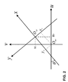
- FIG. 2 illustrates a graphic view showing the relationship between two coordinate planes, (u,v) with the origin at o uv and (x,y) with the origin at o xy ;
- FIG. 3 is a schematic representation of a generalized sequence of computations and/or stages of the computational efficient translation estimation algorithm for two-dimensional images.
- FIG. 4 is a schematic representation of a generalized sequence of computations and/or stages of the computational efficient sub-pixel translation estimation algorithm for two-dimensional images.
- FIG. 5 illustrates a graphic view showing the relationship between two coordinate planes, (k u ,k v ) and (k x ,k y ) in the spatial frequency domain in which the corresponding two origins coincide at o.
- FIG. 6 is a schematic diagram of a generalized sequence of steps representing an algorithm for estimating translation and rotation transformation parameters.
- FIG. 7 is an overall schematic representation of an embodiment of the present invention for reconstructing super-resolved full color images from CFA low-resolution sequences whose green channel images are used to estimate gross translations and sub-pixel translations and rotations among frames.
- FIG. 8 is an overall schematic representation of alternative embodiment of the present invention for reconstructing super-resolved full color images from CFA low-resolution sequences whose green, red, and blue channel images are used to estimate gross translations and sub-pixel translations and rotations among frames.
- FIG. 9 illustrates a graphic view showing the rectangular sampling grid.
- FIG. 10 illustrates a graphic view showing the rectangular sampled spectrum.
- FIG. 11 illustrates a graphic view showing the hexagonal sampling grid.
- FIG. 12 illustrates a graphic view showing the hexagonal sampled spectrum.
- FIG. 13 is a schematic diagram of sequence of steps representing an algorithm for reconstructing CFA green channel.
- FIG. 14 shows the original gray scale image of a nature scene.
- FIG. 15 shows the spectrum of the original image.
- FIG. 16 shows the subsampled rectangular grid for red or blue image which is subsampled by 2 from the original image.
- FIG. 17 shows the red or blue sampled image.
- FIG. 18 shows the spectrum of the red or blue sampled image, in which the repeated versions of the spectrum of the original image are presented in the rectangular sampling fashion.
- FIG. 19 shows the reconstructed red or blue sampled image.
- FIG. 20 shows the hexagonal sampling grid for green image.
- FIG. 21 shows the hexagonal sampled green image.
- FIG. 22 shows the spectrum of the hexagonal sampled green image, in which the repeated versions of the spectrum of the original image are presented in the hexagonal sampling fashion.
- FIG. 23 shows the reconstructed green sampled image.
- FIG. 24 is a graphic view showing an image acquisition model
- FIG. 25 is a graphic view showing factors that dictate the bandwidth of the measured target signature
- FIG. 26 is a graphic view depicting the bandwidth phenomenon in the super-resolution image reconstruction algorithm.
- FIG. 27 is a schematic representation of a sequence of steps representing, inter alia, an error-energy reduction algorithm for CFA input image sequences influenced or affected by both translations and rotations.
- FIG. 28 illustrates an example of super-resolving a full color image from a sequence of CFA input images for a license plate scene. In order to protect the license plate owner's privacy, part of license plate is covered.
- FIG. 29 illustrates an example of super-resolving a full color image from a sequence of CFA input images for a car emblem scene.
- the letter “Ford” shows clearly in the super-resolved luminance image.
- FIG. 30 depicts a high level block diagram of a general purpose computer.
- components of a preferred embodiment of the present invention include gross translation estimation (Box 214 ) and sub-pixel transformation estimation (Box 216 ).
- Gross translation (or shift) estimates are intended to obtain the overall shift of each image with respect to a reference image.
- Sub-pixel transformation also known as fraction pixel displacement, subpixel shift, or subpixel displacement
- Frame-to-frame motion detection based on gradient decent methods are most commonly used (see: (1) U.S. Pat. No. 5,767,987, “Method and apparatus for combining multiple image scans for enhanced resolution,” Jun. 16, 1998, G. J. Wolff and R. J. Van Steenkiste; (2) U.S. Pat. No. 6,650,704, “Method of producing a high quality, high resolution image from a sequence of low quality, low resolution images that are undersampled and subject to jitter,” Nov. 18, 2003, R. S. Carlson, J. L. Arnold, and V. G.
- Pat. No. 7,602,997 invented by the inventor herein, utilizes a correlation method without solving the minimum least square problem to explore the translational differences (shifts in x and y domains) of Fourier transforms of two images to estimate sub-pixel shifts between two low resolution aliased images.
- Two image frames of a low-resolution image sequence may be designated ⁇ 1 (x,y) and ⁇ 2 (u,v). Because of the conditions under which the frames are acquired, the second image is a shifted and/or rotated version of the first image, that is,
- the relation between (x s ,y s ) and (u s ,v s ) can be written as:
- the signal registration method is described in the following. Almost all of the transformation parameter estimation methods are based on the signal registration method. It is assumed that the signals to be matched differ only by an unknown translation. In practice, beside translation, there may be rotation, noise, and geometrical distortions. Nevertheless, the signal registration description offers a fundamental solution to the problem.
- the procedure for pixel-level registration is to first calculate the correlation between two images ⁇ 1 (x,y) and ⁇ 2 (x,y) as:
- a signal registration based correlation method is used for translation parameter estimation between two images based on 1) the correlation theorem; and 2) the shift property of Fourier transform. This method begins with the cross-correlation between two images.
- the terminology “cross-correlation” or “cross correlation” as used herein is a measure of similarity of two frames in terms of a function of one of them.
- the two-dimensional normalized cross-correlation function measures the similarity for each translation:
- Correlation Theorem More efficient signal registration method for translation estimation is using the correlation method in the spatial frequency domain via the Correlation Theorem.
- Fourier transform Properties The properties of Fourier transform are described in the following that include shift property of Fourier transform, polar transformation and polar function mapping, and rotation property of Fourier transform.
- a Fourier transform is an operation that transforms one complex-valued function of a real variable into a new function.
- the domain of the original function is typically space and is accordingly called the spatial domain.
- the domain of the new function is spatial frequency, and so the Fourier transform is often called the spatial frequency domain (or Fourier domain) representation of the original function as it describes which frequencies are present in the original function.
- the terminology “Fourier transform” refers both to the frequency domain representation of a function and to the process or formula that “transforms” one function into the other.
- Shift Property of Fourier Transform Two members of the image sequence are denoted by ⁇ 1 (x,y) and ⁇ 2 (x,y).
- F 2 ( k x ,k y ) F 1 ( k x ,k y )exp[ ⁇ j ( k x ,x s +k y y s )] Equation (9A) where F 1 (k x ,k y ) and F 2 (k x ,k y ) are Fourier transforms of two images.
- F 1 (k x ,k y ) and F 2 (k x ,k y ) are Fourier transforms of two images.
- Polar Transform and Polar Function Mapping The polar transformation of the domain (x,y) for a 2-D signal ⁇ (x,y) may be represented by
- Rotation Property of Fourier Transform Two members of the image sequence are denoted ⁇ 1 (x,y) and ⁇ 2 (u,v), the second image being a rotated version of the first image,
- the gross translation estimation (Box 214 , and, alternatively, Boxes 320 , 340 , 360 ) is described in the following.
- the Fourier transform of the cross-correlation of the two images, ⁇ 1 (x,y) and ⁇ 2 (x,y) that is, the product of the Fourier transform of one image and the complex conjugate of the Fourier transform of the other, can then be expressed as
- sub-pixel shifts (or fractional pixel displacements) among the input images are estimated using a method to estimate or calculate frame-to-frame motion within sub-pixel accuracy.
- the smallest motion that can be obtained from conventional motion estimation is one pixel.
- Obtaining sub-pixel motion accurately is not straightforward.
- a method to achieve the sub-pixel accuracy solution has been described in the aforementioned U.S. Pat. No. 7,602,997. This method is based on resampling via frequency domain interpolation by using a Fourier windowing method as described in S. S. Young, “Alias-free image subsampling using Fourier-based windowing methods,” Optical Engineering, Vol. 43, No. 4, April 2004, pp. 843-855 (hereby incorporated by reference), called power window.
- FIG. 4 A schematic diagram of the computational efficient sub-pixel translation estimation method as described in U.S. Pat. No. 7,602,997 is shown in FIG. 4 .
- the sub-pixel translation and rotational estimation is described in the following. Assuming the second image is a shifted and rotated version of the first image, i.e.,
- FIG. 5 shows the transformation of the two coordinates, (k u ,k v ) and (k x ,k y ), in the spatial frequency domain in which the corresponding two origins coincide.
- Equation (20A) One image is represented as a rotated version of the other image in Equation (16A), while one image is represented as a rotated and shifted version of the other image in Equation (20A).
- the rotation angle difference ⁇ is represented as a translational difference using the polar transformation and polar function mapping of Fourier transform.
- the rotation angle between the two images is estimated in a manner similar to the translation estimation.
- the rotation estimation is described in the following in detail. Because the rotation difference is only represented in the first domain of the Fourier transform, the rotation angle ⁇ is found as the peak of inverse of the marginal 1-D Fourier transform of the cross-correlation with respect to ⁇ .
- the marginal 1-D Fourier transform is an operation of performing the one-dimensional Fourier transform of a 2-D function ⁇ (x,y) with respect to one of the variables, x or y.
- the second image is rotated back by the angle ⁇ to form the backward rotated image ⁇ 2 ⁇ (x,y). Then the shifts (x s ,y s ) between the two images are estimated between ⁇ 2 ⁇ (x,y) and ⁇ 1 (x,y) according to the correlation method based on the Correlation Theorem and the shift property of Fourier transform as discussed previously.
- Rotation and Translation Estimation with Sub-pixel Accuracy Similar as in the translation estimation with sub-pixel accuracy, the rotation estimation with sub-pixel accuracy is achieved by resampling via frequency domain interpolation. However, the resampling operation is only performed in the ⁇ domain (as defined in Equation 13A) since the rotation angle is the only parameter to be estimated.
- the subsequent sub-pixel translation estimation, (x s ,y s ) between the backward rotated image ⁇ 2 ⁇ (x,y) and the first image ⁇ 1 (x,y), is achieved by resampling for both k x and k y domains via frequency domain interpolation (see FIG. 5 ).
- FIG. 6 shows a schematic representation of this estimating algorithm, which may comprise:
- FIGS. 7a, 7b, 8, and 9 An illustration of translation and rotation estimation with sub-pixel accuracy is shown in FIGS. 7a, 7b, 8, and 9 of application Ser. No. 12/576,132.
- a high-resolution forward looking infrared (FLIR) image was used to simulate a sequence of low-resolution undersampled images with translations and rotations.
- FLIR forward looking infrared
- FIG. 7 a of application Ser. No. 12/576,132 An original FLIR tank image is shown in FIG. 7 a of application Ser. No. 12/576,132.
- the size of this image is 40 ⁇ 76.
- the low-resolution images are generated from this simulated high-resolution image by sub-sampling and rotating.
- the randomly selected translation and rotation parameters for six of each low-resolution image are listed as follows:
- FIG. 9 of application Ser. No. 12/576,132 shows the transformation of the plane of one image (image 6) into the target domain of the reference image (image 1).
- FIG. 7 is an overall schematic representation of a preferred embodiment of the present invention.
- a sequence of original input CFA low resolution images is passed into a transformation (including translation and rotation) parameter estimation algorithm (Box 200 ) that includes obtaining gross and sub-pixel transformation parameter estimation algorithm (Box 210 ) for the green channel, from which the reconstructed green channel sequence is obtained (Box 212 ), an estimate of the overall shift of each frame with respect to a reference frame in the green channel sequence is obtained (Box 214 ), and a sub-pixel translation and rotation estimation algorithm (Box 216 ). Since the luminance component in a full color image contains most information and a Bayer color filter array is used in this embodiment, the green channel is chosen as the luminance component for transformation parameter estimation.
- the input images are not aligned with respect to the gross-shift estimates. Rather, both estimated gross and sub-pixel transformation parameters are assigned to the red and blue channel sequences (Box 240 and 250 ).
- the method of acquiring a sequence of images in super-resolution image reconstruction in this embodiment may involve non-controlled sub-pixel translations and rotations; e.g. natural jitter. This can be more cost effective and more practical than the controlled sub-pixel translation and rotation image acquisition.
- the imager may be carried by a moving platform or the object itself may be moving.
- the moving platform may be a person, an unmanned ground vehicle (UGV), or an unmanned aerial vehicle (UAV) flying in a circular motion or a forward motion.
- UAV unmanned ground vehicle
- UAV unmanned aerial vehicle
- the gross translations and the sub-pixel translations and rotations are obtained for each color channel sequence.
- an error reduction algorithm is applied to the input CFA low resolution images with the estimated gross shifts and sub-pixel shifts and/or rotations among images to obtain the high-resolution (alias-free) full color output.
- the output may be either a single high-resolution full color image that is generated from a sequence of CFA low-resolution images or a sequence of high-resolution full color images that are generated from multiple sequences of CFA low-resolution images.
- Green Channel Candidate One important step in super-resolution is to accurately estimate sub-pixel shifts and rotations among low-resolution images. Since the undersampled CFA images are captured either by natural jitter or some kind of controlled motion of the camera, the images of successive frames contain not only the sub-pixel shifts but also the integer pixel shifts.
- the green channel in the Bayer pattern is sampled using a hexagonal sampling pattern. Obtaining the reconstructed green signal is equivalent to the process of reconstructing the original green signal at each pixel location from hexagonal sampled green signal in the Bayer pattern.
- hexagonal sampling we describe the properties of a more common sampling pattern, rectangular sampling.
- ⁇ x and ⁇ y are the sample spacings in the spatial x and y domain respectively.
- FIG. 9 illustrates a 2-D rectangular sampling grid.
- FIG. 10 illustrates the Fourier transform of F ⁇ (k x ,k y ), which is the repeated version of the continuous signal F(k x ,k y ).
- the cutoff frequency in spatial frequency domain is
- ⁇ s ⁇ ⁇ 0 2 ⁇ ⁇ 2 ⁇ ⁇ 0
- ⁇ (k x ,k y ) ⁇ square root over (k x 2 +k y 2 ) ⁇
- ⁇ 0 ⁇ square root over ((1/ ⁇ x ) 2 +(1/ ⁇ y ) 2 ) ⁇ square root over ((1/ ⁇ x ) 2 +(1/ ⁇ y ) 2 ) ⁇ .
- Hexagonal sampling is depicted in the insert in FIG. 11 ; and refers to the pattern formed by replacing the red and blue pixels (in the Bayer pattern shown in FIG. 1 ) with zero values.
- the Fourier transform of the delta-sampled signal, F ⁇ (k x ,k y ) is composed of repeated versions of the Fourier transform of the continuous signal F(k x ,k y ), that is,
- FIG. 11 illustrates a 2-D hexagonal sampling grid.
- FIG. 12 illustrates the Fourier transform of F ⁇ (k x ,k y ), which is the repeated version of the continuous signal F(k x ,k y ). The distances between adjacent two closest repeated spectra in both directions are
- ⁇ s ⁇ ⁇ 0 2 ⁇ ⁇ 2 ⁇ 2 ⁇ ⁇ 0 in the radial spatial frequency as shown in FIG. 12 .
- FIG. 13 is a schematic diagram of sequence of steps representing an algorithm for reconstructing CFA green channel.
- the original green signal ⁇ g (x,y) is passed through an imaging system with the CFA (Box 610 ) to become the hexagonal sampled signal ⁇ g ⁇ (x,y).
- the cutoff frequency for the green channel is designed as
- the inverse Fourier transform of the low-passed signal (Box 650 ), F gL (k x ,k y ), is denoted as ⁇ tilde over ( ⁇ ) ⁇ g (x,y), which is the reconstructed CFA green signal.
- the low-pass filter is obtained by a Fourier windowing method described in S. S. Young, “Alias-free image subsampling using Fourier-based windowing methods,” Optical Engineering, Vol. 43, No. 4, pp. 843-855, April 2004, hereby incorporated by reference.
- Reconstructing red or blue channel is similar to the procedure of reconstructing the green channel except the cutoff frequency for the low-pass filter is designed as
- FIGS. 14-23 An illustration of reconstructing green and red/blue channels is shown in FIGS. 14-23 .
- a gray scale image to simulate a hexagonal sampled green image and a rectangular subsampled red or blue image.
- the subsampled red or blue image is decimated/subsampled by 2 from the original image.
- FIG. 14 The original gray scale image of a nature scene is shown in FIG. 14 . Its spectrum is shown in FIG. 15 . Note that in FIG. 15 the spectrum is centered around the low frequencies.
- the subsampled rectangular grid for red or blue image which is subsampled by 2 (every other pixel is sampled) from the original image is illustrated in FIG. 16 .
- FIG. 17 shows the red or blue sampled image.
- FIG. 18 is the spectrum for the red and blue sampled image. Note that by comparing FIG. 18 with FIG. 10 , one can see that in FIG. 18 the spectrum is repeated at nine locations around the perimeter correlating to the repeated versions of the original spectrum shown FIG. 10 .
- the reconstructing red or blue sampled image is shown in FIG. 19 .
- FIG. 20 The hexagonal sampling grid for the green image is shown in FIG. 20 .
- FIG. 21 shows the hexagonal sampled green image. Its spectrum is shown in FIG. 22 , in which the repeated versions of the spectrum of the original image are presented in the hexagonal sampling fashion. Note that by comparing FIG. 22 to FIG. 12 , one can see repeated versions in the hexagonal sampling pattern as shown in FIG. 12 .
- the reconstructing green sampled image is shown in FIG. 23 .
- the gross translation estimation ( FIG. 7 Box 214 ) as described in the foregoing and in U.S. patent application Ser. No. 12/576,132, “System and Method of Super-Resolution Imaging from a Sequence of Translated and Rotated Low-Resolution Images,” filed Oct. 8, 2009, S. S. Young is illustrated in FIG. 3 .
- the gross translation estimation is applied to the reconstructed green channel images in the preferred embodiment. Then the estimated translations are assigned to the red and blue channels (Box 240 ). If other CFA pattern is used, the gross translation estimation is applied to the reconstructing luminance channel. Then the estimated translations are assigned to two other chrominance channels.
- FIG. 7 Box 214 The gross translation estimation is applied to the reconstructed green channel images in the preferred embodiment. Then the estimated translations are assigned to the red and blue channels (Box 240 ). If other CFA pattern is used, the gross translation estimation is applied to the reconstructing luminance channel. Then the estimated translations are assigned to two other chrominance channels.
- the gross translation estimation is applied to three color channel images, respectively (Box 320 , 340 , 360 ).
- the sub-pixel translation and rotation estimation is applied to the reconstructing luminance channel. Then the estimated translations and rotations are assigned to two other chrominance channels. In the alternative embodiment, the sub-pixel translation and rotation estimation is applied to three color channel images, respectively. One may also use the averages of the estimated translations and rotations for three color channels, respectively, for all three color channels, as used by others.
- Error-Energy Reduction Algorithm for CFA Input Images A primary feature of this proposed error-energy reduction algorithm for CFA images is that, for each color channel, we treat the spatial samples from low-resolution images that possess unknown and irregular (uncontrolled) sub-pixel shifts and/or rotations as a set of constraints to populate an over-sampled (sampled above the desired output bandwidth) processing array. The estimated sub-pixel shifted and rotated locations of these samples and their values constitute a spatial domain constraint. Furthermore, the bandwidth of the alias-free image (or the sensor imposed bandwidth) is the criterion used as a spatial frequency domain constraint on the over-sampled processing array.
- the high-resolution image is reconstructed by removing aliasing from low resolution images.
- the high-resolution image is reconstructed by applying non-uniform interpolation using the constraints both in the spatial and spatial frequency domains.
- the algorithm is based on the concept that the error-energy is reduced by imposing both spatial and spatial frequency domain constraints: the samples from the low-resolution images; and the bandwidth of the high-resolution, alias-free output image.
- spatial samples from low resolution images that possess unknown and irregular (uncontrolled) sub-pixel shifts and rotations are treated as a set of constraints to populate an over-sampled (sampled above the desired output bandwidth) processing array.
- the estimated sub-pixel locations of these samples and their values constitute a spatial domain constraint.
- the bandwidth of the alias-free image (or the sensor imposed bandwidth) is the criterion used as a spatial frequency domain constraint on the over-sampled processing array.
- FIG. 24 shows the system model for acquiring an undersampled image in a one-dimensional case.
- ⁇ (x) be the ideal target signature that is interrogated by the sensor.
- the measured target signature g(x) by the sensor is modeled as the output of a Linear Shift Invariant (LSI) system whose impulse response is the sensor's point spread function (PSF), h(x); this is also known as the sensor blurring function.
- LSI Linear Shift Invariant
- PSF point spread function
- G ( k x ) F ( k x ) H ( k x )
- G(k x ), F(k x ), and H(k x ) are the Fourier transforms of g(x), ⁇ (x), and h(x), respectively.
- FIG. 25 shows the factors that dictate the bandwidth of the measured target signature.
- the bandwidth of the sensor's PSF point spread function
- the bandwidth of the ideal target signature depends on, e.g., the range of the target in FLIR (Forward-Looking Infrared), radar, sonar, visible light, etc.
- FLIR Forward-Looking Infrared
- radar Sonar
- visible light etc.
- the ideal target signature bandwidth is relatively large.
- the ideal target signature bandwidth is smaller.
- Two lines (one dotted and one solid) in FIG. 25 illustrate the bandwidths of the sensor and the ideal target signature.
- the proposed super-resolution image reconstruction algorithm cannot produce an image whose bandwidth exceeds B o , because the de-aliasing approach cannot recover the bandwidth beyond the sensor's diffraction limit.
- An acquired image is aliased when
- the super-resolution image reconstruction algorithm in a preferred embodiment is to de-alias a sequence of undersampled aliased images to obtain the alias-free or a super-resolved image.
- the resolution of the output alias-free image is limited by the minimum bandwidth of the sensor and the ideal target signature.
- An image array of 100 ⁇ 100 is initially acquired to represent a scene.
- the total number of pixels is 10,000. If the resolution of the image is desired to be 4 times in each direction, the image array of 400 ⁇ 400 is required.
- the total number of pixels for the high-resolution image is 160,000. That means that it requires 16 low-resolution images to achieve the resolution improvement factor of 4. Therefore, the number of input low-resolution image frames is the square of the resolution improvement factor. In other words, the resolution improvement factor is the square root of the number of the input images.
- N G ⁇ _ ⁇ SR N 2 ⁇ k , the one for the blue or red channel is
- N C ⁇ _ ⁇ SR N 4 ⁇ k , where C represents for red or blue channel. Therefore, the resolution improvement factor in the green channel is ⁇ square root over (k/2) ⁇ in both x and y directions, and the one in the red or blue channel ⁇ square root over (k/4) ⁇ . That is, for CFA images, let the sampling space of the original undersampled images be ⁇ x . From an information-theory point of view, the sampling space of the output high-resolution full color image that is reconstructed from k frames (with distinct sub-pixel shifts) is
- the resolution improvement factor of the green channel is ⁇ square root over (k/2) ⁇ and the one of the red or blue channel is ⁇ square root over (k/4) ⁇ .
- more frames should provide more information and, thus, larger bandwidth and/or higher resolution.
- the super-resolution image quality does not improve when the number of processed undersampled images exceeds a certain value. This is due to the fact that the bandwidth recovery is limited by the minimum of the bandwidths of the sensor or ideal target signature.
- the bandwidth of the input undersampled (aliased) images is designated B i .
- the bandwidth of the alias-free (high-resolution) output image for that channel is denoted as B o .
- the 2D FFT of the processing array yields a spectral coverage B p that is larger than the bandwidth of the output image.
- FIG. 26 illustrates this phenomenon in the 2D spatial frequency domain for one color channel.
- the high-resolution alias-free image on the processing array (grid) is designated as p D (x,y) where D ⁇ G,C ⁇ , G for the green channel and C ⁇ R,B ⁇ for the red or blue channel.
- the low-resolution (aliased) snap-shots only provide a sub-set of samples of this image.
- the location of each aliased image on the processing grid is dictated by its corresponding sub-pixel shifts and rotations in the (x,y) domain.
- FIG. 27 shows a schematic representation of the error-energy reduction algorithm for CFA input image sequences transformed by translations and/or rotations.
- Inputs to the error energy reduction algorithm are a sequence of low-resolution CFA input images.
- the estimated gross shifts and sub-pixel shifts and/or rotations of each image with respect to the reference image are obtained for each color channel; usually the first image is chosen as the reference image.
- the transform coordinates are calculated from the estimated sub-pixel shifts and rotation angles as follows:
- [ x ⁇ ijl y ⁇ ijl ] [ cos ⁇ ⁇ ⁇ ⁇ l sin ⁇ ⁇ ⁇ ⁇ l - sin ⁇ ⁇ ⁇ ⁇ l cos ⁇ ⁇ ⁇ ⁇ l ] ⁇ [ u i v j ] + [ x ⁇ sl y ⁇ sl ]
- the transform coordinates are the same for all three color channels.
- three processing arrays are initialized for three color channels by populating each grid using the input images according to the estimates of shifts and rotation angles, respectively.
- Each processing array is selected with a sample spacing that is smaller than the sample spacing of the desired high-resolution image.
- D ⁇ ( X m , Y n ) ⁇ f l , D ⁇ ( x ⁇ ijl , y ⁇ ijl ) 0
- the input green channel ⁇ 1,G follows the sampling pattern of the hexagonal sampling shown in FIG. 20
- the input red or blue channel ⁇ 1,C follows the sampling pattern of the rectangular sampling shown in FIG. 16 .
- a 2-D Fourier transform P 1,D (k x ,k y ) is preformed on the processing array, where D ⁇ G,C ⁇ , G for the green channel and C ⁇ R,B ⁇ for the red or blue channel. Its spectrum has a wider bandwidth than the true (desired) output bandwidth. Therefore, the spatial frequency domain constraint (Box 408 ) is applied, that is, replacing zeros outside the desired bandwidth.
- the desired bandwidth for the green channel and the one for red or blue channel are determined first (Box 406 ). Based on the spectral properties of the hexagonal sampling and the resolution improvement factor for the green channel when L CFA images are acquired, the desired bandwidth for the green channel is obtained as
- the inverse 2-D Fourier transform p 2,D (x,y) of the resultant array P 2,D (k x ,k y ) is performed for all three color channels, respectively.
- the resultant inverse array is not a true image because the image values at the known grid locations are not equal to the original image values. Then the spatial domain constraint is applied for all three color channels (Box 412 ), that is, replacing those image values at the known grid locations with the known original image values.
- D ⁇ ( X m , Y n ) ⁇ f l , D ⁇ ( x ⁇ ijl , y ⁇ ijl ) p k , D ⁇ ( X m , Y n ) to form the current iteration output image p k+1,D (X m ,Y n ) from the previous iteration output image p k,D (X m ,Y n ) where D ⁇ G,C ⁇ , G for the green channel and C ⁇ R,B ⁇ for the red or blue channel. That is, the known grid locations are replaced with the known original image values and other grid locations are kept as the previous iteration output image values.
- the use of the available information in the spatial and spatial frequency domains results in a reduction of the energy of the error at each iteration step.
- the error for each of three color channel is defined by
- D ⁇ ( m , n ) ⁇ [ p 2 ⁇ k + 1 , D ⁇ ( X m , Y n ) - p 2 ⁇ k - 1 , D ⁇ ( X m , Y n ) ] 2 where D ⁇ G,C ⁇ , G for the green channel and C ⁇ R,B ⁇ for the red or blue channel.
- SNR 2k+1,D ⁇ SNR max,D (where SNR max,D is a pre-assigned threshold value), and the maximum iteration is not reached (Box 416 ), the iteration continues. If SNR 2k+1,D >SNR max,D , that is, the stopping criterion is satisfied, the iteration is terminated. Before the final super-resolution image is generated, the bandwidth of the output image is reduced (Box 418 ) from B p to B o using the Fourier windowing method (see S. S. Young 2004) for the green, red, and blue channel, respectively. Then the final super-resolved full color image with a desired bandwidth is saved for the output (Box 420 ).
- FIG. 28 shows an example of scene of a license plate.
- One of original CFA input images is shown in the left column.
- the super-resolved three channels including the red, green and blue channels are shown in the middle column. These three images can be used to display as a color image.
- the super-resolved luminance image is shown in the right column.
- the conversion from RGB to luminance is presented in the first row of the following matrix:
- T [ 0.2989 0.5870 0.1140 0.5959 - 0.2744 - 0.3216 0.2115 - 0.5229 0.3114 ] In order to protect the license plate owner's privacy, part of the license plate is covered.
- FIG. 29 Another example of scene of a car emblem is illustrated in FIG. 29 .
- the super-resolved image shows a significant improvement from the CFA low-resolution images by exhibiting the detailed information especially in the digits and letters in the license plate and the car emblem. This illustrates that the super-resolved image is obtained even under the condition that a color filter array image sequence is acquired.
- FIG. 30 depicts a high level block diagram of a general purpose computer suitable for use in performing the functions described herein, including the steps shown in the block diagrams, schematic representations, and/or flowcharts.
- the system 500 includes a processor element 502 (e.g., a CPU) for controlling the overall function of the system 500 .
- Processor 502 operates in accordance with stored computer program code, which is stored in memory 504 .
- Memory 504 represents any type of computer readable medium and may include, for example, RAM, ROM, optical disk, magnetic disk, or a combination of these media.
- the processor 502 executes the computer program code in memory 504 in order to control the functioning of the system 500 .
- Processor 502 is also connected to network interface 505 , which transmits and receives network data packets. Also included are various input/output devices 506 (e.g., storage devices, including but not limited to, a tape drive, a floppy drive, a hard disk drive or compact disk drive, a receiver, a transmitter, a speaker, a display, a speech synthesizer, an output port, and a user input device (such as a keyboard, a keypad, a mouse and the like).
- various input/output devices 506 e.g., storage devices, including but not limited to, a tape drive, a floppy drive, a hard disk drive or compact disk drive, a receiver, a transmitter, a speaker, a display, a speech synthesizer, an output port, and a user input device (such as a keyboard, a keypad, a mouse and the like).
- the terminology “subject” means: an area, a scene, an object or objects, a landscape, overhead view of land or an object or objects, or a combination thereof.
- frame means: a picture, an image or one of the successive pictures on a strip of film or video.
- process means: an algorithm, software, subroutine, computer program, or methodology.
- algorithm means: sequence of steps using computer software, process, software, subroutine, computer program, or methodology.
- ⁇ is a digital image process of reconstructing a full color image from incomplete color samples output from an image sensor or camera overlaid with a color filter array (CFA).
- CFA color filter array
- Demosaicing or demosaicing is also referred to as CFA interpolation or color reconstruction.
- image sensor means: a camera, charge coupled device (CCD), video device, spatial sensor, or range sensor.
- the image sensor may comprise a device having a shutter controlled aperture that, when opened, admits light enabling an object to be focused, usually by means of a lens, onto a surface, thereby producing a photographic image OR a device in which the picture is formed before it is changed into electric impulses.
- transformation refers to changes induced by movement of the image capture device, including translation and rotation.
- processor or “image processor” as used in the following claims includes a computer, multiprocessor, CPU, minicomputer, microprocessor or any machine similar to a computer or processor which is capable of processing algorithms.
- luminance or “luminescence contrast” refers to the difference in luminosity (or lightness) of an object as compared to the background.
- a more detailed description of the human visual reaction to various levels of contrast is found at NASA's Applied Color Science site http://colorusage.arc.nasa.gov/design_lum — 1.php, hereby incorporated by reference.
- the primary colors are been given luminances by design, to achieve white alignment of the monitor.
- Early designers of computer displays decided that equal R, G, and B digital codes should produce a particular neutral chromaticity, the “alignment white” of the monitor (usually 6500K or 5300K).
- the maximum luminances of the primaries were set so that luminances of the primaries would mix to give the alignment white.
- the human eye is more sensitive to the color green.
- the color green is used in the color array of FIG. 1 to a greater extent than red or blue, so that green is designated as the luminescent color.
- luminance contrast in terms of the difference between the lightness of the symbol or text and its background, relative to the display's white-point (maximum) luminance.
- spatial anti-aliasing refers to a technique in which distortion artifacts (also refer to as aliasing) are minimized when creating a high-resolution image at a lower resolution.
- Anti-aliasing relates to the process of removing signal components of a frequency higher than is able to be properly resolved by the optical recording or sampling device.
- color channel is used in the context of a grayscale image of the same size as a color image, made of just one of the primary colors.
- an image from a standard digital camera generally has green, red, and blue channels.
- a grayscale image has just one channel.
- full color includes three primary color channels where three colors are utilized to produce the color image or four or more primary color channels where four or more colors are used to produce the color image.
Abstract
Description
where (x,y) represent the coordinate plane in the first image, and (u,v) represent the coordinate plane in the shifted and rotated second image, as shown in
If the relative shifts (us,vs) are obtained, the shifts (xs,ys) can be obtained. Hereinafter, both (xs,ys) and (us,vs) may be used for the relative shifts. The transformation parameters between images including translation (shift) (xs,ys) and rotation θ are estimated using a signal registration method and properties of Fourier transform.
where 1≦k≦N, 1≦l≦M and R is a similarity measure, such as a normalized cross-correlation or an absolute difference function. For the (N−1, M−1) samples of r(k,l), there is a maximum value of r(xs,ys), where (xs,ys) is the displacement in sampling intervals of ƒ2(x,y) with respect to ƒ1(x,y). Many transformation parameter estimation methods are based on the variations of the signal registration.
where 1≦k≦N, 1≦l≦M and (N,M) is the dimension of the image. If ƒ1(x,y) matches ƒ2(x,y) exactly, except for an intensity scale factor, at a translation of (xs,ys), the cross-correlation has its peak at C(xs,ys). Various implementations and discussions can be found for example in A. Rosenfeld and A. C. Kak, Digital Picture Processing, Vol. II pp. 36-39, Orlando, Fla.: Academic Press, 1982; L. G. Brown, “A survey of image registration techniques,” ACM Computing Survey, Vol. 24, No. 4, December 1992, pp. 325-376), both of which are hereby incorporated by reference.
Q 12(k x ,k y)=ℑ[C(x,y)]=F 2(k x ,k y)·F 1*(k x ,k y) Equation (7A)
where F1(kx,ky) and F2(kx,ky) are Fourier transforms of two images, ƒ1(x,y) and ƒ2(x,y), respectively, F1*(kx,ky) is the conjugate of F1(kx,ky).
ƒ2(x,y)=ƒ1(x−x s ,y−y s) Equation (8A)
where (xs,ys) are the relative shifts (translational differences) between ƒ1(x,y) and ƒ2(x,y). Then,
F 2(k x ,k y)=F 1(k x ,k y)exp[−j(k x ,x s +k y y s)] Equation (9A)
where F1(kx,ky) and F2(kx,ky) are Fourier transforms of two images. Thus, a shift in one domain results in the addition of a linear phase function in the Fourier domain.
Note that ƒ(x,y)≠ƒp(x,y). This equation is called the polar function mapping of ƒ(x,y). The polar function mapping of F(kx,ky) in the spatial frequency domain may be defined via
It is noted that Fp(•,•) is not the Fourier transform of ƒp(•,•).
where θ is the relative rotation (rotational differences) between ƒ1(x,y) and ƒ2(u,v). Then,
F 2(k u ,k v)=F 1(k x ,k y) Equation (14A)
where [ku, kv] and [kx,ky] have the following relation,
Using the polar function mappings of F1(ky,ky) and F2(ku,kv), then
F p2(φ,ρ)=F p1(φ−θ,ρ) (Equation 16A)
That is, if one image is a rotated version of another image, then the polar function mapping of one is the shifted version of the polar function mapping of the other one in the spatial frequency domain.
where (xs,ys) are the relative shifts (translational differences) between ƒ1(x,y) and ƒ2(u,v). The shifts (xs,ys) are found according to the Correlation Theorem based on the signal registration method by exploring the translational differences (shifts in x and y domains) of Fourier transforms of two images.
Q 12(k x ,k y)=ℑ[C(X,y)]=F 2(k x ,k y)·F 1*(k x ,k y) Equation (7A)
where F1(kx,ky) and F2(kx,ky) are Fourier transforms of two images, ƒ1(x,y) and ƒ2(x,y), respectively, F1*(kx,ky) is the conjugate of F1(ky,ky).
F 2(k x ,k y)=F 1(k x ,k y)exp[−j(k x x s +k y y s)] Equation (9A)
Then, the Fourier transform of the cross-correlation of the two images, ƒ1(x,y) and ƒ2(x,y), that is, the product of the Fourier transform of one image and the complex conjugate of the Fourier transform of the other, can then be expressed as
Then, the shifts (xs, ys) are found as the peak of inverse Fourier transform of the cross-correlation, Q12(kx,ky).
where θ is the relative rotation and (us,vs) the relative shifts between ƒ1(x,y) and ƒ2(u,v).
F 2(k u ,k v)=F 1(k x ,k y)·exp[−j(k u u s +k v v s)] Equation (9A)
where F2(ku,kv) and F1(kx,ky) are the Fourier transforms of the two images, and the (ku,kv) domain is the rotated version of the (kx,ky) domain; that is,
F p2(φ,ρ)=F p1(φ−θ,ρ)·exp[−j(k u u s +k v v s)] Equation (19A)
|F p2(φ,ρ)|=|F p1(φ−θ,ρ) Equation (20A)
That is, if one image is a rotated and shifted version of the other image, then the magnitude of polar function mapping of one is the shifted version of the magnitude of polar function mapping of the other one in the spatial frequency domain.
Q P12(k φ,ρ)=ℑp2(k φ,ρ)ℑp1*(k φ,ρ) Equation (21A)
where ℑp1(kφ,ρ) and ℑp2(kφ,ρ) are the marginal 1-D Fourier transforms with respect to φ for the two images |Fp1(φ,ρ)| and |Fp2(φ,ρ)| (as defined in Equation 12A), respectively, and ℑp1 +(kφ,ρ) is the complex conjugate of ℑp1(kφ,ρ).
{tilde over (F)} 1(k x ,k y)=F 1(k x ,k y)·W(k x ,k y) Equation (22AA)
{tilde over (F)} 2(k u ,k v)=F 2(k u ,k v)·W(k u ,k v) Equation (22AB)
Sub-Pixel Rotation and Translation Estimation Procedure
- 1) Input two low-resolution images ƒ1(x,y) and ƒ2(u,v) (Box 30).
- 2) Obtain the 2-D Fourier transforms of the two images, F1(kx,ky) and F2(ku, kv) (Box 31).
- 3) Apply a radially symmetrical window W to the Fourier transforms of the two images to obtain {tilde over (F)}1(kx,ky) and {tilde over (F)}2(ku,kv) (Box 32), see Equation (22AA)-(22AB).
- 4) Construct the magnitudes of the polar function mappings of the two windowed images, |FP1(φ,ρ)| and |FP2(φ,ρ)| (Box 33), as defined in Equation (12A).
- 5) Obtain the marginal 1-D Fourier transforms with respect to φ for the magnitude of the two polar function mappings, ℑP1 (kφ, ρ) and ℑP2(kφ,ρ) (Box 34).
- 6) Form the cross-correlation function of the two images, ℑP1(kφ,ρ) and ℑP2(kφ,ρ), to obtain Qp12(kφ,ρ) (Box 35), see Equation (21A).
- 7) Estimate the rotation angle θ between two images ƒ1(x,y) and ƒ2(u,v) with sub-pixel accuracy from the cross-correlation function Qp12(kφ,ρ) (Box 36).
- 8) Rotate the second image by the angle −θ to form the backward rotated image ƒ2θ(x,y) (Box 37).
- 9) Estimate the relative shift between ƒ2θ(x,y) and ƒ1(x,y) with sub-pixel accuracy to obtain the relative shifts (xs,ys) (Box 38).
Example of Sub-Pixel Rotation and Translation
-
- xs=[0 3.1 7.7 12.3 14.1 17.3];
- ys=[0 2.3 8.5 11.2 15.2 16.8];
- θ=[0 14.4 15.6 17.8 19.1 22.7];
The units of xs and ys are pixels and the unit of θ is degrees. FIG. 8 of application Ser. No. 12/576,132 shows six simulated low-resolution images with shifts and rotates among them.
where xm=mΔx and yn=nΔy, Δx and Δy are the sample spacings in the spatial x and y domain respectively. Then, the Fourier transform of the delta-sampled signal, Fδ(kx,ky), is composed of repeated versions of the Fourier transform of the continuous signal F(kx,ky), that is,
The repeated positions of this Fourier transform are at
for m=(−∞,∞) and n=(−∞,∞). Thus, provided that F(kx,ky) has a finite support in the spatial frequency domain, for example,
where
then ƒ(x,y) can be recovered from ƒδ(x,y) via lowpass filter in the frequency domain.
as shown in
where ρ(kx,ky)=√{square root over (kx 2+ky 2)}, ρ0=√{square root over ((1/Δx)2+(1/Δy)2)}{square root over ((1/Δx)2+(1/Δy)2)}.
in spatial frequency domain,
in radial frequency domain.
Note that rectangular sampling corresponds to the case of b=c=0. The inverse of the hexagonal transformation is also linear, that is,
The Jacobian of the hexagonal transformation is
Next, define
g(α,β)=ƒ(x,y)
or, equivalently
g[T 1(x,y),T 2(x,y)]=ƒ(x,y)
It is assumed that the imaging system provides evenly spaced samples of g(α,β) in the (α,β) measurement domain, for example, αm=mΔα and βn=nΔβ. Our task is to reconstruct the function ƒ(x,y) from the available samples at (xmn,ymn), where
αm =mΔ α =T 1(x mn ,y mn)
βn =nΔ β =T 2(x mn ,y mn)
δ(x−x m ,y−y n)=|T′(x,y)|δ(α−αm,β−βn).
The delta-sampled signal is defined via
Using above equation, ƒδ(x,y) is rewritten as follows:
Then, the Fourier transform of the delta-sampled signal, Fδ(kx,ky), is composed of repeated versions of the Fourier transform of the continuous signal F(kx,ky), that is,
Using T1(x,y)=ax+by and T2(x,y)=cx+dy, the above equation can be rewritten as:
where
The repeated positions of this Fourier transform are at (kxmn, kymn) for m=(−∞,∞) and n=(−∞,∞).
That is, a=1, b=1, c=−1, and d=1.
for m=(−∞,∞) and n=(−∞,∞).
The cutoff frequency is designed as
in spatial frequency domain, and
in the radial spatial frequency as shown in
in spatial frequency domain, and
in the radial spatial frequency (Box 630) based on the spectrum property of the CFA green signal. A low-pass filtering Wg(kx,ky) with the cutoff frequency ρs0,G (Box 640) is applied to the Fourier transform Fgδ(kx,ky) (Box 620) to generate FgL(kx,ky). That is,
F gL(k x ,k y)=F gδ(k x ,k y)W g(k x ,k y).
Then the inverse Fourier transform of the low-passed signal (Box 650), FgL(kx,ky), is denoted as {tilde over (ƒ)}g(x,y), which is the reconstructed CFA green signal. The low-pass filter is obtained by a Fourier windowing method described in S. S. Young, “Alias-free image subsampling using Fourier-based windowing methods,” Optical Engineering, Vol. 43, No. 4, pp. 843-855, April 2004, hereby incorporated by reference.
in spatial frequency domain,
in radial frequency domain, where C for red or blue channel.
Example of Reconstructing Green and Red/Blue Channels
G(k x)=F(k x)H(k x)
where G(kx), F(kx), and H(kx) are the Fourier transforms of g(x), ƒ(x), and h(x), respectively.
B o=min(B t ,B s)
where Bo, Bt and Bs are the bandwidths of the output target signature, the ideal target signature and the sensor PSF, respectively. The proposed super-resolution image reconstruction algorithm cannot produce an image whose bandwidth exceeds Bo, because the de-aliasing approach cannot recover the bandwidth beyond the sensor's diffraction limit.
in one-dimensional imaging systems, and
in two-dimensional imaging systems.
the one for the blue or red channel is
where C represents for red or blue channel. Therefore, the resolution improvement factor in the green channel is √{square root over (k/2)} in both x and y directions, and the one in the red or blue channel √{square root over (k/4)}. That is, for CFA images, let the sampling space of the original undersampled images be Δx. From an information-theory point of view, the sampling space of the output high-resolution full color image that is reconstructed from k frames (with distinct sub-pixel shifts) is
in the green channel,
in the red or blue channel in two-dimensional imaging systems. In another words, the resolution improvement factor of the green channel is √{square root over (k/2)} and the one of the red or blue channel is √{square root over (k/4)}.
In the preferred embodiment, the transform coordinates are the same for all three color channels.
where Dε{G,C}, G for the green channel and Cε{R,B} for the red or blue channel, (Xm,Yn) is the grid location that is closest to the transformation coordinates [{circumflex over (x)}ijl, ŷijl], and m=1, 2, . . . , M, n=1, 2, . . . , N; M×N is the dimension of the processing grid. The input green channel ƒ1,G follows the sampling pattern of the hexagonal sampling shown in
in the spatial frequency domain. From the spectral properties of the rectangular sampling and the resolution improvement factor for the red or blue channel when L CFA images acquired, the desired bandwidth for the red or blue channel is obtained as
in the spatial frequency domain.
The functions
P 2,D(k x ,k y)=P 1,D(k x ,k y)·W p,D(k x ,k y)
is formed where Wp,D(kx,ky) is a windowing function of realizing the spatial frequency domain constraint using (BOx,G,BOy,G) for the green channel and (BOx,c, BOy,C) for the red or blue channel, respectively. In
to form the current iteration output image pk+1,D(Xm,Yn) from the previous iteration output image pk,D(Xm,Yn) where Dε{G,C}, G for the green channel and Cε{R,B} for the red or blue channel. That is, the known grid locations are replaced with the known original image values and other grid locations are kept as the previous iteration output image values.
where Dε{G,C}, G for the green channel and Cε{R,B} for the red or blue channel.
where Dε{G,C}, G for the green channel and Cε{R,B} for the red or blue channel. If SNR2k+1,D<SNRmax,D (where SNRmax,D is a pre-assigned threshold value), and the maximum iteration is not reached (Box 416), the iteration continues. If SNR2k+1,D>SNRmax,D, that is, the stopping criterion is satisfied, the iteration is terminated. Before the final super-resolution image is generated, the bandwidth of the output image is reduced (Box 418) from Bp to Bo using the Fourier windowing method (see S. S. Young 2004) for the green, red, and blue channel, respectively. Then the final super-resolved full color image with a desired bandwidth is saved for the output (Box 420).
In order to protect the license plate owner's privacy, part of the license plate is covered.
Claims (22)
Priority Applications (1)
| Application Number | Priority Date | Filing Date | Title |
|---|---|---|---|
| US12/968,881 US8577184B2 (en) | 2005-01-19 | 2010-12-15 | System and method for super-resolution imaging from a sequence of color filter array (CFA) low-resolution images |
Applications Claiming Priority (3)
| Application Number | Priority Date | Filing Date | Title |
|---|---|---|---|
| US11/038,401 US7602997B2 (en) | 2005-01-19 | 2005-01-19 | Method of super-resolving images |
| US12/576,132 US7856154B2 (en) | 2005-01-19 | 2009-10-08 | System and method of super-resolution imaging from a sequence of translated and rotated low-resolution images |
| US12/968,881 US8577184B2 (en) | 2005-01-19 | 2010-12-15 | System and method for super-resolution imaging from a sequence of color filter array (CFA) low-resolution images |
Related Parent Applications (1)
| Application Number | Title | Priority Date | Filing Date |
|---|---|---|---|
| US12/576,132 Continuation-In-Part US7856154B2 (en) | 2005-01-19 | 2009-10-08 | System and method of super-resolution imaging from a sequence of translated and rotated low-resolution images |
Publications (2)
| Publication Number | Publication Date |
|---|---|
| US20110142366A1 US20110142366A1 (en) | 2011-06-16 |
| US8577184B2 true US8577184B2 (en) | 2013-11-05 |
Family
ID=44142994
Family Applications (1)
| Application Number | Title | Priority Date | Filing Date |
|---|---|---|---|
| US12/968,881 Expired - Fee Related US8577184B2 (en) | 2005-01-19 | 2010-12-15 | System and method for super-resolution imaging from a sequence of color filter array (CFA) low-resolution images |
Country Status (1)
| Country | Link |
|---|---|
| US (1) | US8577184B2 (en) |
Cited By (31)
| Publication number | Priority date | Publication date | Assignee | Title |
|---|---|---|---|---|
| US20090195664A1 (en) * | 2005-08-25 | 2009-08-06 | Mediapod Llc | System and apparatus for increasing quality and efficiency of film capture and methods of use thereof |
| US9218641B1 (en) * | 2012-06-19 | 2015-12-22 | Exelis, Inc. | Algorithm for calculating high accuracy image slopes |
| US9558419B1 (en) | 2014-06-27 | 2017-01-31 | Blinker, Inc. | Method and apparatus for receiving a location of a vehicle service center from an image |
| US9563814B1 (en) | 2014-06-27 | 2017-02-07 | Blinker, Inc. | Method and apparatus for recovering a vehicle identification number from an image |
| US9589201B1 (en) | 2014-06-27 | 2017-03-07 | Blinker, Inc. | Method and apparatus for recovering a vehicle value from an image |
| US9589202B1 (en) | 2014-06-27 | 2017-03-07 | Blinker, Inc. | Method and apparatus for receiving an insurance quote from an image |
| US9594971B1 (en) | 2014-06-27 | 2017-03-14 | Blinker, Inc. | Method and apparatus for receiving listings of similar vehicles from an image |
| US9600733B1 (en) | 2014-06-27 | 2017-03-21 | Blinker, Inc. | Method and apparatus for receiving car parts data from an image |
| US9607236B1 (en) | 2014-06-27 | 2017-03-28 | Blinker, Inc. | Method and apparatus for providing loan verification from an image |
| US9754171B1 (en) | 2014-06-27 | 2017-09-05 | Blinker, Inc. | Method and apparatus for receiving vehicle information from an image and posting the vehicle information to a website |
| US9760776B1 (en) | 2014-06-27 | 2017-09-12 | Blinker, Inc. | Method and apparatus for obtaining a vehicle history report from an image |
| US9773184B1 (en) | 2014-06-27 | 2017-09-26 | Blinker, Inc. | Method and apparatus for receiving a broadcast radio service offer from an image |
| US9779318B1 (en) | 2014-06-27 | 2017-10-03 | Blinker, Inc. | Method and apparatus for verifying vehicle ownership from an image |
| US9818154B1 (en) | 2014-06-27 | 2017-11-14 | Blinker, Inc. | System and method for electronic processing of vehicle transactions based on image detection of vehicle license plate |
| US9892337B1 (en) | 2014-06-27 | 2018-02-13 | Blinker, Inc. | Method and apparatus for receiving a refinancing offer from an image |
| US10242284B2 (en) | 2014-06-27 | 2019-03-26 | Blinker, Inc. | Method and apparatus for providing loan verification from an image |
| US20190235114A1 (en) * | 2015-05-08 | 2019-08-01 | King Fahd University Of Petroleum And Minerals | Method for processing marine seismic data |
| US10515285B2 (en) | 2014-06-27 | 2019-12-24 | Blinker, Inc. | Method and apparatus for blocking information from an image |
| US10540564B2 (en) | 2014-06-27 | 2020-01-21 | Blinker, Inc. | Method and apparatus for identifying vehicle information from an image |
| US10572758B1 (en) | 2014-06-27 | 2020-02-25 | Blinker, Inc. | Method and apparatus for receiving a financing offer from an image |
| US10733471B1 (en) | 2014-06-27 | 2020-08-04 | Blinker, Inc. | Method and apparatus for receiving recall information from an image |
| US10830545B2 (en) | 2016-07-12 | 2020-11-10 | Fractal Heatsink Technologies, LLC | System and method for maintaining efficiency of a heat sink |
| US10846824B2 (en) | 2017-12-08 | 2020-11-24 | Tata Consultancy Services Limited | Systems and methods for reconstructing super-resolution images under total aliasing based upon translation values |
| US10867327B1 (en) | 2014-06-27 | 2020-12-15 | Blinker, Inc. | System and method for electronic processing of vehicle transactions based on image detection of vehicle license plate |
| US11041799B2 (en) | 2019-06-04 | 2021-06-22 | Carl Zeiss Industrielle Messtechnik Gmbh | Device for 3D measurement of object coordinates |
| US11127116B2 (en) * | 2015-12-01 | 2021-09-21 | Sony Corporation | Surgery control apparatus, surgery control method, program, and surgery system |
| US20220101494A1 (en) * | 2020-09-30 | 2022-03-31 | Nvidia Corporation | Fourier transform-based image synthesis using neural networks |
| US11454493B2 (en) | 2020-01-31 | 2022-09-27 | Carl Zeiss Industrielle Messtechnik Gmbh | Method and arrangement for determining a position and/or an alignment of a movable object of an arrangement of objects |
| WO2022263923A1 (en) | 2021-06-17 | 2022-12-22 | Creal Sa | Techniques for generating light field data by combining multiple synthesized viewpoints |
| US11598593B2 (en) | 2010-05-04 | 2023-03-07 | Fractal Heatsink Technologies LLC | Fractal heat transfer device |
| US11948293B2 (en) | 2020-01-31 | 2024-04-02 | Carl Zeiss Industrielle Messtechnik Gmbh | Method and arrangement for determining a position of an object |
Families Citing this family (17)
| Publication number | Priority date | Publication date | Assignee | Title |
|---|---|---|---|---|
| US8159555B2 (en) * | 2007-09-13 | 2012-04-17 | Eastman Kodak Company | Method for infrared image correction and enhancement |
| DE102008034979B4 (en) * | 2008-07-25 | 2011-07-07 | EADS Deutschland GmbH, 85521 | Method and device for generating error-reduced high-resolution and contrast-enhanced images |
| US8724928B2 (en) * | 2009-08-31 | 2014-05-13 | Intellectual Ventures Fund 83 Llc | Using captured high and low resolution images |
| US8487929B2 (en) * | 2009-09-09 | 2013-07-16 | Advanced Micro Devices, Inc. | Resolution enhancement of video stream based on spatial and temporal correlation |
| US8179445B2 (en) * | 2010-03-03 | 2012-05-15 | Eastman Kodak Company | Providing improved high resolution image |
| US8675085B2 (en) * | 2010-07-14 | 2014-03-18 | James Randall Beckers | Camera that combines images of different scene depths |
| KR102131326B1 (en) * | 2013-08-22 | 2020-07-07 | 삼성전자 주식회사 | Image Frame Motion Estimation Device, Encoding Method Thereof |
| WO2016114845A1 (en) * | 2015-01-15 | 2016-07-21 | Cohn Avi | Improved sorting system |
| US9906691B2 (en) * | 2015-03-25 | 2018-02-27 | Tripurari Singh | Methods and system for sparse blue sampling |
| WO2017056787A1 (en) * | 2015-09-29 | 2017-04-06 | 富士フイルム株式会社 | Image processing device, image processing method and program |
| US10152772B2 (en) | 2016-01-18 | 2018-12-11 | Advanced Micro Devices, Inc. | Techniques for sampling sub-pixels of an image |
| US10368071B2 (en) * | 2017-11-03 | 2019-07-30 | Arm Limited | Encoding data arrays |
| CN112384945A (en) * | 2018-08-09 | 2021-02-19 | 谷歌有限责任公司 | Super-resolution using natural handheld motion applied to user devices |
| US11276145B2 (en) * | 2019-09-06 | 2022-03-15 | Apple Inc. | Seamless preview stitching for multiple cameras |
| US11076151B2 (en) | 2019-09-30 | 2021-07-27 | Ati Technologies Ulc | Hierarchical histogram calculation with application to palette table derivation |
| US11915337B2 (en) | 2020-03-13 | 2024-02-27 | Advanced Micro Devices, Inc. | Single pass downsampler |
| US20230018183A1 (en) * | 2021-07-15 | 2023-01-19 | Aptiv Technologies Limited | De-Aliased Imaging for a Synthetic Aperture Radar |
Citations (28)
| Publication number | Priority date | Publication date | Assignee | Title |
|---|---|---|---|---|
| US5696848A (en) * | 1995-03-09 | 1997-12-09 | Eastman Kodak Company | System for creating a high resolution image from a sequence of lower resolution motion images |
| US5767987A (en) | 1994-09-26 | 1998-06-16 | Ricoh Corporation | Method and apparatus for combining multiple image scans for enhanced resolution |
| US5952957A (en) * | 1998-05-01 | 1999-09-14 | The United States Of America As Represented By The Secretary Of The Navy | Wavelet transform of super-resolutions based on radar and infrared sensor fusion |
| US6023535A (en) | 1995-08-31 | 2000-02-08 | Ricoh Company, Ltd. | Methods and systems for reproducing a high resolution image from sample data |
| US6157732A (en) | 1997-03-18 | 2000-12-05 | Cognex Corporation | Image processing system and method using subsampling with constraints such as time and uncertainty constraints |
| US6208765B1 (en) | 1998-06-19 | 2001-03-27 | Sarnoff Corporation | Method and apparatus for improving image resolution |
| US6285804B1 (en) | 1998-12-21 | 2001-09-04 | Sharp Laboratories Of America, Inc. | Resolution improvement from multiple images of a scene containing motion at fractional pixel values |
| US6344893B1 (en) | 2000-06-19 | 2002-02-05 | Ramot University Authority For Applied Research And Industrial Development Ltd. | Super-resolving imaging system |
| US6349154B1 (en) | 1997-12-22 | 2002-02-19 | U.S. Philips Corporation | Method and Arrangement for creating a high-resolution still picture |
| US6424749B1 (en) | 1999-03-30 | 2002-07-23 | Matsushita Electric Industrial Co., Ltd. | System and method for scaling combined video and computer generated imagery |
| US6483952B2 (en) | 1998-05-20 | 2002-11-19 | Itt Manufacturing Enterprises, Inc. | Super resolution methods for electro-optical systems |
| US6628845B1 (en) | 1999-10-20 | 2003-09-30 | Nec Laboratories America, Inc. | Method for subpixel registration of images |
| US6642497B1 (en) | 2002-06-14 | 2003-11-04 | Hewlett-Packard Development Company, Lp. | System for improving image resolution via sensor rotation |
| US6650704B1 (en) | 1999-10-25 | 2003-11-18 | Irvine Sensors Corporation | Method of producing a high quality, high resolution image from a sequence of low quality, low resolution images that are undersampled and subject to jitter |
| US20040239885A1 (en) | 2003-04-19 | 2004-12-02 | University Of Kentucky Research Foundation | Super-resolution overlay in multi-projector displays |
| US20040263169A1 (en) * | 2003-06-27 | 2004-12-30 | Mitchell J. Ross | Synthetic aperture MRI |
| US20050019000A1 (en) * | 2003-06-27 | 2005-01-27 | In-Keon Lim | Method of restoring and reconstructing super-resolution image from low-resolution compressed image |
| US20050057687A1 (en) * | 2001-12-26 | 2005-03-17 | Michael Irani | System and method for increasing space or time resolution in video |
| US20060038891A1 (en) * | 2003-01-31 | 2006-02-23 | Masatoshi Okutomi | Method for creating high resolution color image, system for creating high resolution color image and program creating high resolution color image |
| US20060053455A1 (en) | 2002-12-04 | 2006-03-09 | Murali Mani | Synchronization of signals |
| US20060159369A1 (en) * | 2005-01-19 | 2006-07-20 | U.S. Army Research Laboratory | Method of super-resolving images |
| US7106914B2 (en) | 2003-02-27 | 2006-09-12 | Microsoft Corporation | Bayesian image super resolution |
| US20060279585A1 (en) | 2004-12-17 | 2006-12-14 | Peyman Milanfar | System and method for robust multi-frame demosaicing and color super resolution |
| US20070130095A1 (en) | 2005-09-30 | 2007-06-07 | Peot Mark A | Bayesian approach for sensor super-resolution |
| US20070196009A1 (en) | 2006-02-10 | 2007-08-23 | Frank Deinzer | Method for operating an X-ray diagnostic device for the generation of high-resolution images |
| US20070206678A1 (en) | 2006-03-03 | 2007-09-06 | Satoshi Kondo | Image processing method and image processing device |
| US20070217713A1 (en) * | 2004-12-16 | 2007-09-20 | Peyman Milanfar | Robust reconstruction of high resolution grayscale images from a sequence of low resolution frames |
| US7323681B1 (en) | 2003-09-11 | 2008-01-29 | Applera Corporation | Image enhancement by sub-pixel imaging |
-
2010
- 2010-12-15 US US12/968,881 patent/US8577184B2/en not_active Expired - Fee Related
Patent Citations (28)
| Publication number | Priority date | Publication date | Assignee | Title |
|---|---|---|---|---|
| US5767987A (en) | 1994-09-26 | 1998-06-16 | Ricoh Corporation | Method and apparatus for combining multiple image scans for enhanced resolution |
| US5696848A (en) * | 1995-03-09 | 1997-12-09 | Eastman Kodak Company | System for creating a high resolution image from a sequence of lower resolution motion images |
| US6023535A (en) | 1995-08-31 | 2000-02-08 | Ricoh Company, Ltd. | Methods and systems for reproducing a high resolution image from sample data |
| US6157732A (en) | 1997-03-18 | 2000-12-05 | Cognex Corporation | Image processing system and method using subsampling with constraints such as time and uncertainty constraints |
| US6349154B1 (en) | 1997-12-22 | 2002-02-19 | U.S. Philips Corporation | Method and Arrangement for creating a high-resolution still picture |
| US5952957A (en) * | 1998-05-01 | 1999-09-14 | The United States Of America As Represented By The Secretary Of The Navy | Wavelet transform of super-resolutions based on radar and infrared sensor fusion |
| US6483952B2 (en) | 1998-05-20 | 2002-11-19 | Itt Manufacturing Enterprises, Inc. | Super resolution methods for electro-optical systems |
| US6208765B1 (en) | 1998-06-19 | 2001-03-27 | Sarnoff Corporation | Method and apparatus for improving image resolution |
| US6285804B1 (en) | 1998-12-21 | 2001-09-04 | Sharp Laboratories Of America, Inc. | Resolution improvement from multiple images of a scene containing motion at fractional pixel values |
| US6424749B1 (en) | 1999-03-30 | 2002-07-23 | Matsushita Electric Industrial Co., Ltd. | System and method for scaling combined video and computer generated imagery |
| US6628845B1 (en) | 1999-10-20 | 2003-09-30 | Nec Laboratories America, Inc. | Method for subpixel registration of images |
| US6650704B1 (en) | 1999-10-25 | 2003-11-18 | Irvine Sensors Corporation | Method of producing a high quality, high resolution image from a sequence of low quality, low resolution images that are undersampled and subject to jitter |
| US6344893B1 (en) | 2000-06-19 | 2002-02-05 | Ramot University Authority For Applied Research And Industrial Development Ltd. | Super-resolving imaging system |
| US20050057687A1 (en) * | 2001-12-26 | 2005-03-17 | Michael Irani | System and method for increasing space or time resolution in video |
| US6642497B1 (en) | 2002-06-14 | 2003-11-04 | Hewlett-Packard Development Company, Lp. | System for improving image resolution via sensor rotation |
| US20060053455A1 (en) | 2002-12-04 | 2006-03-09 | Murali Mani | Synchronization of signals |
| US20060038891A1 (en) * | 2003-01-31 | 2006-02-23 | Masatoshi Okutomi | Method for creating high resolution color image, system for creating high resolution color image and program creating high resolution color image |
| US7106914B2 (en) | 2003-02-27 | 2006-09-12 | Microsoft Corporation | Bayesian image super resolution |
| US20040239885A1 (en) | 2003-04-19 | 2004-12-02 | University Of Kentucky Research Foundation | Super-resolution overlay in multi-projector displays |
| US20050019000A1 (en) * | 2003-06-27 | 2005-01-27 | In-Keon Lim | Method of restoring and reconstructing super-resolution image from low-resolution compressed image |
| US20040263169A1 (en) * | 2003-06-27 | 2004-12-30 | Mitchell J. Ross | Synthetic aperture MRI |
| US7323681B1 (en) | 2003-09-11 | 2008-01-29 | Applera Corporation | Image enhancement by sub-pixel imaging |
| US20070217713A1 (en) * | 2004-12-16 | 2007-09-20 | Peyman Milanfar | Robust reconstruction of high resolution grayscale images from a sequence of low resolution frames |
| US20060279585A1 (en) | 2004-12-17 | 2006-12-14 | Peyman Milanfar | System and method for robust multi-frame demosaicing and color super resolution |
| US20060159369A1 (en) * | 2005-01-19 | 2006-07-20 | U.S. Army Research Laboratory | Method of super-resolving images |
| US20070130095A1 (en) | 2005-09-30 | 2007-06-07 | Peot Mark A | Bayesian approach for sensor super-resolution |
| US20070196009A1 (en) | 2006-02-10 | 2007-08-23 | Frank Deinzer | Method for operating an X-ray diagnostic device for the generation of high-resolution images |
| US20070206678A1 (en) | 2006-03-03 | 2007-09-06 | Satoshi Kondo | Image processing method and image processing device |
Non-Patent Citations (28)
| Title |
|---|
| A. Dumitras and F. Kossentini, "High-order image subsampling using feedforward artificial neural networks," IEEE Trans. Image Process. 10(3), 427-435 (2001). |
| A. Landmark, N. Wadstromer, and H. Li, "Hierarchical subsampling giving fractal regions," IEEE Trans. Image Process. 10(1), 167-173 (2001). |
| A. M. Guarnieri, C. Prati, and F. Rocca, "SAR interferometric quick-look," Proc. Geosci. Remote Sens. Symp. IGARSS '93 3, 988-990 (1993). |
| A. Papoulis, Chapter 14, Probability Random Variables, and Stochastic Processes, McGraw-Hill Book Company Inc., New York, 1984, pp. 480-499. |
| A. S. Fruchter, et al., "Drizzle: A Method for the Linear Reconstruction of Undersampled Images," Publications of the Astronomical Society of the Pacific, vol. 114, pp. 144-152, Feb. 2002 [arXiv:astro-ph/9808087v2 Oct. 19, 2001]. |
| Alleysson, D., et al. "Frequency Selection Demosaicking: A Review and a Look Ahead," (Proceedings Paper) Visual Communications and Image Processing 2008, SPIE-IS& T vol. 6822, p. 68221M-1 to 68221M-13. (Jan. 28, 2008). |
| B. E. Schmitz and R. L. Stevenson, "The enhancement of images containing subsampled chrominance information," IEEE Trans. Image Process. 6(7), 1052-1056 (1997). |
| B. J. Geiman, L. N. Bohs, M. E. Anderson, S. M. Breit, and G. E. Trahey, "A novel interpolation startegy for estimating subsample speckle motion," Phys. Med. Biol. 45(6), 1541-1552 (Jun. 2000). |
| B.C. Tom and A.K. Katsaggelos, "Reconstruction of a High-resolution Image by Simultaneous Registration, Restoration, and Interpolation of Low-resolution Images," Proceedings of 1995 IEEE Int. Conf. Image Processing, col. 2, Washington, DC, Oct. 1995, pp. 539-542. |
| Gerchberg, "Super Resolution Through Error Energy Reduction," OPTICA ACTS, vol. 21, No. 9, pp. 709-720 (1974). |
| H. Stark and P. Oskoui, "High-resolution image recovery from image-plane arrays, using convex projections," J. Opt. Soc. Am. A, vol. 6, No. 11, pp. 1715-1726, Nov. 1989. |
| Irani, M., et al. "Super Resolution From Image Sequences," Proceedings of the 10th International Conference on Pattern Recognition, vol. 2, pp. 115-120, 1990. |
| J. O. Kim, B. T. Choi, A. Morales, and S. J. Ko, "Neural concurrent subsampling and interpolation for images," Proc. IEEE 2, 1327-1330 (1999). |
| J. R. Casas and L. Torres, "Morphological filter for lossless image subsampling," Proc. Int. Conf. Image Process. ICIP-94 2, 903-907 (1994). |
| L. G. Brown, "A survey of image registration techniques," ACM Computing Survey, vol. 24, No. 4, Dec. 1992, pp. 325-376. |
| Li, Xin, et al. "Image Demosaicing: A Systematic Survey," Visual Communications and Image Processing 2008, SPIE-IS& T vol. 6822, pp. 68221j-1 to 68221j-15 (2008). |
| M. Irani and S. Peleg, "Improving Resolution by Image Registration," CVGIP: Graphical Models and Image Processing, vol. 53, pp. 231-239, May 1991. |
| M. Soumekh, Fourier Array Imaging, Prentice Hall, 1994, pp. 167-177. |
| Prabhu, K.A., et al., "Motion Compensated Component Color Coding," IEEE Transactions on Communications, vol. COM-30, No. 12, Dec. 1982, pp. 2519-2527. |
| R. A. F. Belfor, M. P. A. Hesp, R. L. Lagendijk, and J. Biemond, "Spatially adaptive subsampling of image sequences," IEEE Trans. Image Process. 3(5), 492-500 (1994). |
| R. C. Hardie, K.J. Barnard, and E. E. Armstrong, "Joint MAP registration and high-resolution image estimation using a sequence of undersampled images," IEEE Trans. Image Processing, vol. 6, pp. 1621-1633, Dec. 1997. |
| R. Leptoukh, S. Ahmad, P. Eaton, M. Hegde, S. Kempler, J. Koziana, D. Ostrenga, D. Ouzounov, A. Savtchenko, G. Serafina, A. K. Sharma, and B. Zhou, "GES DAAC tools for accessing and visualizing MODIS data," Proc. Geosci. Remote Sens. Symp. IGARSS '02 6, 3202-3204 (2002). |
| R.R. R Schulz and R. L. Stevenson, "Extraction of high-resolution frames from video sequences," IEEE Trans. Image Processing, vol. 5, pp. 996-1011, Jun. 1996. |
| R.Y. Tsai and T.S. Huang, "Mulitple Frame Image Restoration and Registration," Advances in Computer Vision and Image Processing, Greenwich CT: JAI Press, Inc. 1984, pp. 317-339. |
| Rosenfeld, et al., "Digital Picture Processing," Second Edition, vol. 2, pp. 36-39 (1982). |
| S. Foucher, G. B. Benie, and J. M. Boucher, "Multiscale MAP filtering of SAR images," IEEE Trans. Image Process. 10 (1), 49-60 (Jan. 2001). |
| S. S. Young, "Alias-free image subsampling using Fourier-based windowing methods," Optical Engineering, vol. 43, No. 4, Apr. 2004, pp. 843-855. |
| Tom, B.C., et al. "Resolution Enhancement of Monochrome and Color Video Using Motion Compensation," IEEE Transactions on Image Processing, vol. 10, No. 2, Feb. 2001, pp. 278-287. |
Cited By (51)
| Publication number | Priority date | Publication date | Assignee | Title |
|---|---|---|---|---|
| US20090195664A1 (en) * | 2005-08-25 | 2009-08-06 | Mediapod Llc | System and apparatus for increasing quality and efficiency of film capture and methods of use thereof |
| US8767080B2 (en) * | 2005-08-25 | 2014-07-01 | Cedar Crest Partners Inc. | System and apparatus for increasing quality and efficiency of film capture and methods of use thereof |
| US11598593B2 (en) | 2010-05-04 | 2023-03-07 | Fractal Heatsink Technologies LLC | Fractal heat transfer device |
| US9218641B1 (en) * | 2012-06-19 | 2015-12-22 | Exelis, Inc. | Algorithm for calculating high accuracy image slopes |
| US10210417B2 (en) | 2014-06-27 | 2019-02-19 | Blinker, Inc. | Method and apparatus for receiving a refinancing offer from an image |
| US10210396B2 (en) | 2014-06-27 | 2019-02-19 | Blinker Inc. | Method and apparatus for receiving vehicle information from an image and posting the vehicle information to a website |
| US9589202B1 (en) | 2014-06-27 | 2017-03-07 | Blinker, Inc. | Method and apparatus for receiving an insurance quote from an image |
| US9594971B1 (en) | 2014-06-27 | 2017-03-14 | Blinker, Inc. | Method and apparatus for receiving listings of similar vehicles from an image |
| US9600733B1 (en) | 2014-06-27 | 2017-03-21 | Blinker, Inc. | Method and apparatus for receiving car parts data from an image |
| US9607236B1 (en) | 2014-06-27 | 2017-03-28 | Blinker, Inc. | Method and apparatus for providing loan verification from an image |
| US9754171B1 (en) | 2014-06-27 | 2017-09-05 | Blinker, Inc. | Method and apparatus for receiving vehicle information from an image and posting the vehicle information to a website |
| US9760776B1 (en) | 2014-06-27 | 2017-09-12 | Blinker, Inc. | Method and apparatus for obtaining a vehicle history report from an image |
| US9773184B1 (en) | 2014-06-27 | 2017-09-26 | Blinker, Inc. | Method and apparatus for receiving a broadcast radio service offer from an image |
| US9779318B1 (en) | 2014-06-27 | 2017-10-03 | Blinker, Inc. | Method and apparatus for verifying vehicle ownership from an image |
| US9818154B1 (en) | 2014-06-27 | 2017-11-14 | Blinker, Inc. | System and method for electronic processing of vehicle transactions based on image detection of vehicle license plate |
| US9892337B1 (en) | 2014-06-27 | 2018-02-13 | Blinker, Inc. | Method and apparatus for receiving a refinancing offer from an image |
| US10163025B2 (en) | 2014-06-27 | 2018-12-25 | Blinker, Inc. | Method and apparatus for receiving a location of a vehicle service center from an image |
| US10163026B2 (en) | 2014-06-27 | 2018-12-25 | Blinker, Inc. | Method and apparatus for recovering a vehicle identification number from an image |
| US10169675B2 (en) | 2014-06-27 | 2019-01-01 | Blinker, Inc. | Method and apparatus for receiving listings of similar vehicles from an image |
| US10176531B2 (en) | 2014-06-27 | 2019-01-08 | Blinker, Inc. | Method and apparatus for receiving an insurance quote from an image |
| US10192114B2 (en) | 2014-06-27 | 2019-01-29 | Blinker, Inc. | Method and apparatus for obtaining a vehicle history report from an image |
| US10192130B2 (en) | 2014-06-27 | 2019-01-29 | Blinker, Inc. | Method and apparatus for recovering a vehicle value from an image |
| US10204282B2 (en) | 2014-06-27 | 2019-02-12 | Blinker, Inc. | Method and apparatus for verifying vehicle ownership from an image |
| US11436652B1 (en) | 2014-06-27 | 2022-09-06 | Blinker Inc. | System and method for electronic processing of vehicle transactions based on image detection of vehicle license plate |
| US9563814B1 (en) | 2014-06-27 | 2017-02-07 | Blinker, Inc. | Method and apparatus for recovering a vehicle identification number from an image |
| US10210416B2 (en) | 2014-06-27 | 2019-02-19 | Blinker, Inc. | Method and apparatus for receiving a broadcast radio service offer from an image |
| US9558419B1 (en) | 2014-06-27 | 2017-01-31 | Blinker, Inc. | Method and apparatus for receiving a location of a vehicle service center from an image |
| US10242284B2 (en) | 2014-06-27 | 2019-03-26 | Blinker, Inc. | Method and apparatus for providing loan verification from an image |
| US10572758B1 (en) | 2014-06-27 | 2020-02-25 | Blinker, Inc. | Method and apparatus for receiving a financing offer from an image |
| US10515285B2 (en) | 2014-06-27 | 2019-12-24 | Blinker, Inc. | Method and apparatus for blocking information from an image |
| US10540564B2 (en) | 2014-06-27 | 2020-01-21 | Blinker, Inc. | Method and apparatus for identifying vehicle information from an image |
| US9589201B1 (en) | 2014-06-27 | 2017-03-07 | Blinker, Inc. | Method and apparatus for recovering a vehicle value from an image |
| US10579892B1 (en) | 2014-06-27 | 2020-03-03 | Blinker, Inc. | Method and apparatus for recovering license plate information from an image |
| US10733471B1 (en) | 2014-06-27 | 2020-08-04 | Blinker, Inc. | Method and apparatus for receiving recall information from an image |
| US10885371B2 (en) | 2014-06-27 | 2021-01-05 | Blinker Inc. | Method and apparatus for verifying an object image in a captured optical image |
| US10867327B1 (en) | 2014-06-27 | 2020-12-15 | Blinker, Inc. | System and method for electronic processing of vehicle transactions based on image detection of vehicle license plate |
| US10436925B2 (en) * | 2015-05-08 | 2019-10-08 | King Fahd University Of Petroleum And Minerals | Method for processing marine seismic data |
| US20190235114A1 (en) * | 2015-05-08 | 2019-08-01 | King Fahd University Of Petroleum And Minerals | Method for processing marine seismic data |
| US11127116B2 (en) * | 2015-12-01 | 2021-09-21 | Sony Corporation | Surgery control apparatus, surgery control method, program, and surgery system |
| US10830545B2 (en) | 2016-07-12 | 2020-11-10 | Fractal Heatsink Technologies, LLC | System and method for maintaining efficiency of a heat sink |
| US11609053B2 (en) | 2016-07-12 | 2023-03-21 | Fractal Heatsink Technologies LLC | System and method for maintaining efficiency of a heat sink |
| US11913737B2 (en) | 2016-07-12 | 2024-02-27 | Fractal Heatsink Technologies LLC | System and method for maintaining efficiency of a heat sink |
| US11346620B2 (en) | 2016-07-12 | 2022-05-31 | Fractal Heatsink Technologies, LLC | System and method for maintaining efficiency of a heat sink |
| US10846824B2 (en) | 2017-12-08 | 2020-11-24 | Tata Consultancy Services Limited | Systems and methods for reconstructing super-resolution images under total aliasing based upon translation values |
| US11041799B2 (en) | 2019-06-04 | 2021-06-22 | Carl Zeiss Industrielle Messtechnik Gmbh | Device for 3D measurement of object coordinates |
| DE102019208114B4 (en) | 2019-06-04 | 2022-03-17 | Carl Zeiss Industrielle Messtechnik Gmbh | Device and method for 3D measurement of object coordinates |
| US11454493B2 (en) | 2020-01-31 | 2022-09-27 | Carl Zeiss Industrielle Messtechnik Gmbh | Method and arrangement for determining a position and/or an alignment of a movable object of an arrangement of objects |
| US11948293B2 (en) | 2020-01-31 | 2024-04-02 | Carl Zeiss Industrielle Messtechnik Gmbh | Method and arrangement for determining a position of an object |
| US20220101494A1 (en) * | 2020-09-30 | 2022-03-31 | Nvidia Corporation | Fourier transform-based image synthesis using neural networks |
| US11570418B2 (en) | 2021-06-17 | 2023-01-31 | Creal Sa | Techniques for generating light field data by combining multiple synthesized viewpoints |
| WO2022263923A1 (en) | 2021-06-17 | 2022-12-22 | Creal Sa | Techniques for generating light field data by combining multiple synthesized viewpoints |
Also Published As
| Publication number | Publication date |
|---|---|
| US20110142366A1 (en) | 2011-06-16 |
Similar Documents
| Publication | Publication Date | Title |
|---|---|---|
| US8577184B2 (en) | System and method for super-resolution imaging from a sequence of color filter array (CFA) low-resolution images | |
| US8666196B2 (en) | System and method for super-resolution imaging from a sequence of color filter array (CFA) low-resolution images | |
| US7602997B2 (en) | Method of super-resolving images | |
| US7515747B2 (en) | Method for creating high resolution color image, system for creating high resolution color image and program creating high resolution color image | |
| US5901242A (en) | Method and apparatus for decoding spatiochromatically multiplexed color images using predetermined coefficients | |
| US7940282B2 (en) | System and method for robust multi-frame demosaicing and color super resolution | |
| US20100067822A1 (en) | System and method of super-resolution imaging from a sequence of translated and rotated low-resolution images | |
| US8040558B2 (en) | Apparatus and method for shift invariant differential (SID) image data interpolation in fully populated shift invariant matrix | |
| US20070133903A1 (en) | System and method for providing multi-sensor super-resolution | |
| Mihoubi et al. | Multispectral demosaicing using intensity-based spectral correlation | |
| US9336570B2 (en) | Demosaicking system and method for color array based multi-spectral sensors | |
| Amba et al. | N-LMMSE demosaicing for spectral filter arrays | |
| Kwan et al. | Debayering RGBW color filter arrays: A pansharpening approach | |
| Simpkins et al. | An introduction to super-resolution imaging | |
| US9906691B2 (en) | Methods and system for sparse blue sampling | |
| US8213710B2 (en) | Apparatus and method for shift invariant differential (SID) image data interpolation in non-fully populated shift invariant matrix | |
| De Lavarène et al. | Practical implementation of LMMSE demosaicing using luminance and chrominance spaces | |
| EP2550808A2 (en) | Method and system for robust and flexible extraction of image information using color filter arrays | |
| Rathi et al. | A New Generic Progressive Approach based on Spectral Difference for Single-sensor Multispectral Imaging System. | |
| Shao et al. | Partition-based interpolation for color filter array demosaicking and super-resolution reconstruction | |
| WO2015083502A1 (en) | Image processing device, method and program | |
| Zhao et al. | PPI Edge Infused Spatial-Spectral Adaptive Residual Network for Multispectral Filter Array Image Demosaicing | |
| Young et al. | Super-resolution image reconstruction from a sequence of aliased imagery | |
| US20050031222A1 (en) | Filter kernel generation by treating algorithms as block-shift invariant | |
| Tsagkatakis et al. | A self-similar and sparse approach for spectral mosaic snapshot recovery |
Legal Events
| Date | Code | Title | Description |
|---|---|---|---|
| AS | Assignment |
Owner name: ARMY, THE UNITED STATES OF AMERICA AS REPRESENTED Free format text: ASSIGNMENT OF ASSIGNORS INTEREST;ASSIGNOR:YOUNG, SHIQION SUSAN;REEL/FRAME:025597/0247 Effective date: 20101215 |
|
| STCF | Information on status: patent grant |
Free format text: PATENTED CASE |
|
| FPAY | Fee payment |
Year of fee payment: 4 |
|
| FEPP | Fee payment procedure |
Free format text: MAINTENANCE FEE REMINDER MAILED (ORIGINAL EVENT CODE: REM.); ENTITY STATUS OF PATENT OWNER: LARGE ENTITY |
|
| LAPS | Lapse for failure to pay maintenance fees |
Free format text: PATENT EXPIRED FOR FAILURE TO PAY MAINTENANCE FEES (ORIGINAL EVENT CODE: EXP.); ENTITY STATUS OF PATENT OWNER: LARGE ENTITY |
|
| STCH | Information on status: patent discontinuation |
Free format text: PATENT EXPIRED DUE TO NONPAYMENT OF MAINTENANCE FEES UNDER 37 CFR 1.362 |
|
| FP | Lapsed due to failure to pay maintenance fee |
Effective date: 20211105 |