US8597455B1 - Translucent building material comprising corrugated cardboard - Google Patents
Translucent building material comprising corrugated cardboard Download PDFInfo
- Publication number
- US8597455B1 US8597455B1 US12/896,334 US89633410A US8597455B1 US 8597455 B1 US8597455 B1 US 8597455B1 US 89633410 A US89633410 A US 89633410A US 8597455 B1 US8597455 B1 US 8597455B1
- Authority
- US
- United States
- Prior art keywords
- tile
- component
- corrugated
- cardboard
- block
- Prior art date
- Legal status (The legal status is an assumption and is not a legal conclusion. Google has not performed a legal analysis and makes no representation as to the accuracy of the status listed.)
- Active, expires
Links
- 239000011111 cardboard Substances 0.000 title claims abstract description 161
- 239000004566 building material Substances 0.000 title claims description 12
- 239000000463 material Substances 0.000 claims abstract description 143
- 239000003795 chemical substances by application Substances 0.000 claims abstract description 93
- 238000000576 coating method Methods 0.000 claims abstract description 72
- 239000011248 coating agent Substances 0.000 claims abstract description 71
- 238000004519 manufacturing process Methods 0.000 claims abstract description 20
- 238000003754 machining Methods 0.000 claims abstract description 13
- 238000009738 saturating Methods 0.000 claims abstract description 13
- 238000000034 method Methods 0.000 claims description 71
- 239000004593 Epoxy Substances 0.000 claims description 60
- 239000000853 adhesive Substances 0.000 claims description 50
- 230000001070 adhesive effect Effects 0.000 claims description 50
- 230000008569 process Effects 0.000 claims description 49
- 229920000647 polyepoxide Polymers 0.000 claims description 36
- 238000005520 cutting process Methods 0.000 claims description 24
- 229920005989 resin Polymers 0.000 claims description 18
- 239000011347 resin Substances 0.000 claims description 18
- 229920001187 thermosetting polymer Polymers 0.000 claims description 14
- 229920000608 Polyaspartic Polymers 0.000 claims description 12
- 125000003700 epoxy group Chemical group 0.000 claims description 10
- 239000004952 Polyamide Substances 0.000 claims description 8
- 229920002396 Polyurea Polymers 0.000 claims description 8
- 229920002647 polyamide Polymers 0.000 claims description 8
- 239000004014 plasticizer Substances 0.000 claims description 5
- 229920006397 acrylic thermoplastic Polymers 0.000 claims description 4
- 229920003229 poly(methyl methacrylate) Polymers 0.000 claims description 4
- 150000004760 silicates Chemical class 0.000 claims description 4
- 125000005625 siliconate group Chemical group 0.000 claims description 4
- ISXSCDLOGDJUNJ-UHFFFAOYSA-N tert-butyl prop-2-enoate Chemical compound CC(C)(C)OC(=O)C=C ISXSCDLOGDJUNJ-UHFFFAOYSA-N 0.000 claims description 4
- 230000036961 partial effect Effects 0.000 claims description 3
- 229920006395 saturated elastomer Polymers 0.000 abstract description 16
- 238000010276 construction Methods 0.000 abstract description 6
- 238000009434 installation Methods 0.000 abstract description 6
- 239000010410 layer Substances 0.000 description 123
- 239000004848 polyfunctional curative Substances 0.000 description 28
- 239000003822 epoxy resin Substances 0.000 description 26
- IISBACLAFKSPIT-UHFFFAOYSA-N bisphenol A Chemical compound C=1C=C(O)C=CC=1C(C)(C)C1=CC=C(O)C=C1 IISBACLAFKSPIT-UHFFFAOYSA-N 0.000 description 22
- 231100000647 material safety data sheet Toxicity 0.000 description 20
- ISWSIDIOOBJBQZ-UHFFFAOYSA-N Phenol Chemical compound OC1=CC=CC=C1 ISWSIDIOOBJBQZ-UHFFFAOYSA-N 0.000 description 19
- 239000000047 product Substances 0.000 description 19
- 229920003023 plastic Polymers 0.000 description 15
- 239000004033 plastic Substances 0.000 description 15
- 239000011521 glass Substances 0.000 description 14
- 229920000642 polymer Polymers 0.000 description 13
- 238000009966 trimming Methods 0.000 description 13
- 229940106691 bisphenol a Drugs 0.000 description 11
- 238000010586 diagram Methods 0.000 description 11
- 239000011241 protective layer Substances 0.000 description 11
- 125000006850 spacer group Chemical group 0.000 description 11
- 239000007795 chemical reaction product Substances 0.000 description 10
- 229920000768 polyamine Polymers 0.000 description 10
- 239000002023 wood Substances 0.000 description 10
- 101100230900 Arabidopsis thaliana HEXO1 gene Proteins 0.000 description 9
- 101100412393 Saccharomyces cerevisiae (strain ATCC 204508 / S288c) REG1 gene Proteins 0.000 description 9
- 229960003742 phenol Drugs 0.000 description 9
- 239000007787 solid Substances 0.000 description 9
- 238000005516 engineering process Methods 0.000 description 8
- 230000009477 glass transition Effects 0.000 description 8
- 229910052751 metal Inorganic materials 0.000 description 8
- 239000002184 metal Substances 0.000 description 8
- XLYOFNOQVPJJNP-UHFFFAOYSA-N water Substances O XLYOFNOQVPJJNP-UHFFFAOYSA-N 0.000 description 8
- RNLHGQLZWXBQNY-UHFFFAOYSA-N 3-(aminomethyl)-3,5,5-trimethylcyclohexan-1-amine Chemical compound CC1(C)CC(N)CC(C)(CN)C1 RNLHGQLZWXBQNY-UHFFFAOYSA-N 0.000 description 7
- FDLQZKYLHJJBHD-UHFFFAOYSA-N [3-(aminomethyl)phenyl]methanamine Chemical compound NCC1=CC=CC(CN)=C1 FDLQZKYLHJJBHD-UHFFFAOYSA-N 0.000 description 7
- NIXOWILDQLNWCW-UHFFFAOYSA-N acrylic acid group Chemical group C(C=C)(=O)O NIXOWILDQLNWCW-UHFFFAOYSA-N 0.000 description 7
- 230000007613 environmental effect Effects 0.000 description 7
- 239000010408 film Substances 0.000 description 7
- WSFSSNUMVMOOMR-NJFSPNSNSA-N methanone Chemical compound O=[14CH2] WSFSSNUMVMOOMR-NJFSPNSNSA-N 0.000 description 7
- 239000002699 waste material Substances 0.000 description 7
- 102100029075 Exonuclease 1 Human genes 0.000 description 6
- 101000918264 Homo sapiens Exonuclease 1 Proteins 0.000 description 6
- 229910000831 Steel Inorganic materials 0.000 description 6
- 125000001931 aliphatic group Chemical group 0.000 description 6
- 230000008901 benefit Effects 0.000 description 6
- 230000015572 biosynthetic process Effects 0.000 description 6
- PXKLMJQFEQBVLD-UHFFFAOYSA-N bisphenol F Chemical compound C1=CC(O)=CC=C1CC1=CC=C(O)C=C1 PXKLMJQFEQBVLD-UHFFFAOYSA-N 0.000 description 6
- 230000000694 effects Effects 0.000 description 6
- 238000010030 laminating Methods 0.000 description 6
- 239000010959 steel Substances 0.000 description 6
- BRLQWZUYTZBJKN-UHFFFAOYSA-N Epichlorohydrin Chemical compound ClCC1CO1 BRLQWZUYTZBJKN-UHFFFAOYSA-N 0.000 description 5
- 239000000654 additive Substances 0.000 description 5
- -1 aromatic glycidyl ethers Chemical class 0.000 description 5
- 239000003063 flame retardant Substances 0.000 description 5
- 230000000149 penetrating effect Effects 0.000 description 5
- VYPSYNLAJGMNEJ-UHFFFAOYSA-N silicon dioxide Inorganic materials O=[Si]=O VYPSYNLAJGMNEJ-UHFFFAOYSA-N 0.000 description 5
- VILCJCGEZXAXTO-UHFFFAOYSA-N 2,2,2-tetramine Chemical compound NCCNCCNCCN VILCJCGEZXAXTO-UHFFFAOYSA-N 0.000 description 4
- CSCPPACGZOOCGX-UHFFFAOYSA-N Acetone Chemical compound CC(C)=O CSCPPACGZOOCGX-UHFFFAOYSA-N 0.000 description 4
- 229920000049 Carbon (fiber) Polymers 0.000 description 4
- 238000010521 absorption reaction Methods 0.000 description 4
- 230000000996 additive effect Effects 0.000 description 4
- 239000004917 carbon fiber Substances 0.000 description 4
- 238000013461 design Methods 0.000 description 4
- 230000005611 electricity Effects 0.000 description 4
- 239000012530 fluid Substances 0.000 description 4
- 239000012760 heat stabilizer Substances 0.000 description 4
- VNWKTOKETHGBQD-UHFFFAOYSA-N methane Chemical compound C VNWKTOKETHGBQD-UHFFFAOYSA-N 0.000 description 4
- 238000012545 processing Methods 0.000 description 4
- 238000004064 recycling Methods 0.000 description 4
- 239000007921 spray Substances 0.000 description 4
- RNFJDJUURJAICM-UHFFFAOYSA-N 2,2,4,4,6,6-hexaphenoxy-1,3,5-triaza-2$l^{5},4$l^{5},6$l^{5}-triphosphacyclohexa-1,3,5-triene Chemical compound N=1P(OC=2C=CC=CC=2)(OC=2C=CC=CC=2)=NP(OC=2C=CC=CC=2)(OC=2C=CC=CC=2)=NP=1(OC=1C=CC=CC=1)OC1=CC=CC=C1 RNFJDJUURJAICM-UHFFFAOYSA-N 0.000 description 3
- POAOYUHQDCAZBD-UHFFFAOYSA-N 2-butoxyethanol Chemical compound CCCCOCCO POAOYUHQDCAZBD-UHFFFAOYSA-N 0.000 description 3
- QTBSBXVTEAMEQO-UHFFFAOYSA-N Acetic acid Chemical compound CC(O)=O QTBSBXVTEAMEQO-UHFFFAOYSA-N 0.000 description 3
- KFZMGEQAYNKOFK-UHFFFAOYSA-N Isopropanol Chemical compound CC(C)O KFZMGEQAYNKOFK-UHFFFAOYSA-N 0.000 description 3
- VVQNEPGJFQJSBK-UHFFFAOYSA-N Methyl methacrylate Chemical compound COC(=O)C(C)=C VVQNEPGJFQJSBK-UHFFFAOYSA-N 0.000 description 3
- 229920005372 Plexiglas® Polymers 0.000 description 3
- 239000004830 Super Glue Substances 0.000 description 3
- 239000002131 composite material Substances 0.000 description 3
- ZBCBWPMODOFKDW-UHFFFAOYSA-N diethanolamine Chemical compound OCCNCCO ZBCBWPMODOFKDW-UHFFFAOYSA-N 0.000 description 3
- FGBJXOREULPLGL-UHFFFAOYSA-N ethyl cyanoacrylate Chemical compound CCOC(=O)C(=C)C#N FGBJXOREULPLGL-UHFFFAOYSA-N 0.000 description 3
- 230000014509 gene expression Effects 0.000 description 3
- 239000003292 glue Substances 0.000 description 3
- 238000009413 insulation Methods 0.000 description 3
- 239000004611 light stabiliser Substances 0.000 description 3
- 230000000670 limiting effect Effects 0.000 description 3
- 239000000314 lubricant Substances 0.000 description 3
- 239000000203 mixture Substances 0.000 description 3
- 239000002667 nucleating agent Substances 0.000 description 3
- 238000004806 packaging method and process Methods 0.000 description 3
- 239000000123 paper Substances 0.000 description 3
- WVDDGKGOMKODPV-ZQBYOMGUSA-N phenyl(114C)methanol Chemical compound O[14CH2]C1=CC=CC=C1 WVDDGKGOMKODPV-ZQBYOMGUSA-N 0.000 description 3
- 238000006116 polymerization reaction Methods 0.000 description 3
- 239000012763 reinforcing filler Substances 0.000 description 3
- 235000012239 silicon dioxide Nutrition 0.000 description 3
- 238000005507 spraying Methods 0.000 description 3
- 239000010409 thin film Substances 0.000 description 3
- XMNDMAQKWSQVOV-UHFFFAOYSA-N (2-methylphenyl) diphenyl phosphate Chemical group CC1=CC=CC=C1OP(=O)(OC=1C=CC=CC=1)OC1=CC=CC=C1 XMNDMAQKWSQVOV-UHFFFAOYSA-N 0.000 description 2
- YXIWHUQXZSMYRE-UHFFFAOYSA-N 1,3-benzothiazole-2-thiol Chemical compound C1=CC=C2SC(S)=NC2=C1 YXIWHUQXZSMYRE-UHFFFAOYSA-N 0.000 description 2
- 241001269524 Dura Species 0.000 description 2
- IGFHQQFPSIBGKE-UHFFFAOYSA-N Nonylphenol Natural products CCCCCCCCCC1=CC=C(O)C=C1 IGFHQQFPSIBGKE-UHFFFAOYSA-N 0.000 description 2
- 229920005830 Polyurethane Foam Polymers 0.000 description 2
- GWEVSGVZZGPLCZ-UHFFFAOYSA-N Titan oxide Chemical compound O=[Ti]=O GWEVSGVZZGPLCZ-UHFFFAOYSA-N 0.000 description 2
- XLOMVQKBTHCTTD-UHFFFAOYSA-N Zinc monoxide Chemical compound [Zn]=O XLOMVQKBTHCTTD-UHFFFAOYSA-N 0.000 description 2
- 230000002745 absorbent Effects 0.000 description 2
- 239000002250 absorbent Substances 0.000 description 2
- 238000009825 accumulation Methods 0.000 description 2
- 239000002390 adhesive tape Substances 0.000 description 2
- 150000001412 amines Chemical class 0.000 description 2
- 238000013459 approach Methods 0.000 description 2
- 238000006243 chemical reaction Methods 0.000 description 2
- 150000001875 compounds Chemical class 0.000 description 2
- 230000008602 contraction Effects 0.000 description 2
- 229920006037 cross link polymer Polymers 0.000 description 2
- 238000007598 dipping method Methods 0.000 description 2
- 229920001971 elastomer Polymers 0.000 description 2
- 239000000839 emulsion Substances 0.000 description 2
- 238000009408 flooring Methods 0.000 description 2
- 230000005484 gravity Effects 0.000 description 2
- 239000011796 hollow space material Substances 0.000 description 2
- BHEPBYXIRTUNPN-UHFFFAOYSA-N hydridophosphorus(.) (triplet) Chemical class [PH] BHEPBYXIRTUNPN-UHFFFAOYSA-N 0.000 description 2
- 238000005470 impregnation Methods 0.000 description 2
- 239000011229 interlayer Substances 0.000 description 2
- 239000011159 matrix material Substances 0.000 description 2
- 230000007246 mechanism Effects 0.000 description 2
- 238000003801 milling Methods 0.000 description 2
- 230000007935 neutral effect Effects 0.000 description 2
- SNQQPOLDUKLAAF-UHFFFAOYSA-N nonylphenol Chemical compound CCCCCCCCCC1=CC=CC=C1O SNQQPOLDUKLAAF-UHFFFAOYSA-N 0.000 description 2
- 239000000049 pigment Substances 0.000 description 2
- 239000011496 polyurethane foam Substances 0.000 description 2
- 238000004886 process control Methods 0.000 description 2
- 239000010453 quartz Substances 0.000 description 2
- 239000005060 rubber Substances 0.000 description 2
- 230000007704 transition Effects 0.000 description 2
- 230000000007 visual effect Effects 0.000 description 2
- 239000012855 volatile organic compound Substances 0.000 description 2
- 239000001993 wax Substances 0.000 description 2
- YHMYGUUIMTVXNW-UHFFFAOYSA-N 1,3-dihydrobenzimidazole-2-thione Chemical compound C1=CC=C2NC(S)=NC2=C1 YHMYGUUIMTVXNW-UHFFFAOYSA-N 0.000 description 1
- YEYKMVJDLWJFOA-UHFFFAOYSA-N 2-propoxyethanol Chemical compound CCCOCCO YEYKMVJDLWJFOA-UHFFFAOYSA-N 0.000 description 1
- XMTQQYYKAHVGBJ-UHFFFAOYSA-N 3-(3,4-DICHLOROPHENYL)-1,1-DIMETHYLUREA Chemical compound CN(C)C(=O)NC1=CC=C(Cl)C(Cl)=C1 XMTQQYYKAHVGBJ-UHFFFAOYSA-N 0.000 description 1
- CZRCFAOMWRAFIC-UHFFFAOYSA-N 5-(tetradecyloxy)-2-furoic acid Chemical compound CCCCCCCCCCCCCCOC1=CC=C(C(O)=O)O1 CZRCFAOMWRAFIC-UHFFFAOYSA-N 0.000 description 1
- QTBSBXVTEAMEQO-UHFFFAOYSA-M Acetate Chemical compound CC([O-])=O QTBSBXVTEAMEQO-UHFFFAOYSA-M 0.000 description 1
- LCFVJGUPQDGYKZ-UHFFFAOYSA-N Bisphenol A diglycidyl ether Chemical compound C=1C=C(OCC2OC2)C=CC=1C(C)(C)C(C=C1)=CC=C1OCC1CO1 LCFVJGUPQDGYKZ-UHFFFAOYSA-N 0.000 description 1
- OKTJSMMVPCPJKN-UHFFFAOYSA-N Carbon Chemical compound [C] OKTJSMMVPCPJKN-UHFFFAOYSA-N 0.000 description 1
- 239000004819 Drying adhesive Substances 0.000 description 1
- YNQLUTRBYVCPMQ-UHFFFAOYSA-N Ethylbenzene Chemical compound CCC1=CC=CC=C1 YNQLUTRBYVCPMQ-UHFFFAOYSA-N 0.000 description 1
- 241000257303 Hymenoptera Species 0.000 description 1
- 229920004142 LEXAN™ Polymers 0.000 description 1
- KEQFTVQCIQJIQW-UHFFFAOYSA-N N-Phenyl-2-naphthylamine Chemical compound C=1C=C2C=CC=CC2=CC=1NC1=CC=CC=C1 KEQFTVQCIQJIQW-UHFFFAOYSA-N 0.000 description 1
- 239000004677 Nylon Substances 0.000 description 1
- 229920002292 Nylon 6 Polymers 0.000 description 1
- 229920002302 Nylon 6,6 Polymers 0.000 description 1
- 239000004698 Polyethylene Substances 0.000 description 1
- 229920002873 Polyethylenimine Polymers 0.000 description 1
- GOOHAUXETOMSMM-UHFFFAOYSA-N Propylene oxide Chemical compound CC1CO1 GOOHAUXETOMSMM-UHFFFAOYSA-N 0.000 description 1
- 239000012790 adhesive layer Substances 0.000 description 1
- IMUDHTPIFIBORV-UHFFFAOYSA-N aminoethylpiperazine Chemical compound NCCN1CCNCC1 IMUDHTPIFIBORV-UHFFFAOYSA-N 0.000 description 1
- 229920006125 amorphous polymer Polymers 0.000 description 1
- 150000004945 aromatic hydrocarbons Chemical class 0.000 description 1
- 230000004888 barrier function Effects 0.000 description 1
- 239000011324 bead Substances 0.000 description 1
- 230000009286 beneficial effect Effects 0.000 description 1
- XUCHXOAWJMEFLF-UHFFFAOYSA-N bisphenol F diglycidyl ether Chemical compound C1OC1COC(C=C1)=CC=C1CC(C=C1)=CC=C1OCC1CO1 XUCHXOAWJMEFLF-UHFFFAOYSA-N 0.000 description 1
- 230000000903 blocking effect Effects 0.000 description 1
- 238000007664 blowing Methods 0.000 description 1
- 230000001680 brushing effect Effects 0.000 description 1
- 239000006229 carbon black Substances 0.000 description 1
- 239000004567 concrete Substances 0.000 description 1
- 239000004020 conductor Substances 0.000 description 1
- 150000001879 copper Chemical class 0.000 description 1
- 238000004132 cross linking Methods 0.000 description 1
- 229910002026 crystalline silica Inorganic materials 0.000 description 1
- XXKOQQBKBHUATC-UHFFFAOYSA-N cyclohexylmethylcyclohexane Chemical compound C1CCCCC1CC1CCCCC1 XXKOQQBKBHUATC-UHFFFAOYSA-N 0.000 description 1
- 238000005034 decoration Methods 0.000 description 1
- 230000001627 detrimental effect Effects 0.000 description 1
- 238000007865 diluting Methods 0.000 description 1
- 238000002845 discoloration Methods 0.000 description 1
- 238000009826 distribution Methods 0.000 description 1
- 238000011143 downstream manufacturing Methods 0.000 description 1
- 230000035622 drinking Effects 0.000 description 1
- 239000005293 duran Substances 0.000 description 1
- 150000002118 epoxides Chemical group 0.000 description 1
- 150000002148 esters Chemical class 0.000 description 1
- 230000003203 everyday effect Effects 0.000 description 1
- 239000000835 fiber Substances 0.000 description 1
- 239000011094 fiberboard Substances 0.000 description 1
- 239000012467 final product Substances 0.000 description 1
- 229920001973 fluoroelastomer Polymers 0.000 description 1
- 239000003365 glass fiber Substances 0.000 description 1
- 239000010439 graphite Substances 0.000 description 1
- 229910002804 graphite Inorganic materials 0.000 description 1
- 150000002366 halogen compounds Chemical class 0.000 description 1
- LNEPOXFFQSENCJ-UHFFFAOYSA-N haloperidol Chemical compound C1CC(O)(C=2C=CC(Cl)=CC=2)CCN1CCCC(=O)C1=CC=C(F)C=C1 LNEPOXFFQSENCJ-UHFFFAOYSA-N 0.000 description 1
- 238000010438 heat treatment Methods 0.000 description 1
- 238000010348 incorporation Methods 0.000 description 1
- 150000002484 inorganic compounds Chemical class 0.000 description 1
- 229910010272 inorganic material Inorganic materials 0.000 description 1
- 238000003780 insertion Methods 0.000 description 1
- 230000037431 insertion Effects 0.000 description 1
- 239000002346 layers by function Substances 0.000 description 1
- 229920005610 lignin Polymers 0.000 description 1
- 239000003550 marker Substances 0.000 description 1
- 230000000873 masking effect Effects 0.000 description 1
- 239000008204 material by function Substances 0.000 description 1
- 238000005259 measurement Methods 0.000 description 1
- 239000000155 melt Substances 0.000 description 1
- 238000002844 melting Methods 0.000 description 1
- 230000008018 melting Effects 0.000 description 1
- 239000003595 mist Substances 0.000 description 1
- CWQXQMHSOZUFJS-UHFFFAOYSA-N molybdenum disulfide Chemical compound S=[Mo]=S CWQXQMHSOZUFJS-UHFFFAOYSA-N 0.000 description 1
- 229910052982 molybdenum disulfide Inorganic materials 0.000 description 1
- 239000000178 monomer Substances 0.000 description 1
- NATWUQFQFMZVMT-UHFFFAOYSA-N n-ethyl-2-methylbenzenesulfonamide Chemical compound CCNS(=O)(=O)C1=CC=CC=C1C NATWUQFQFMZVMT-UHFFFAOYSA-N 0.000 description 1
- OHPZPBNDOVQJMH-UHFFFAOYSA-N n-ethyl-4-methylbenzenesulfonamide Chemical compound CCNS(=O)(=O)C1=CC=C(C)C=C1 OHPZPBNDOVQJMH-UHFFFAOYSA-N 0.000 description 1
- 239000002105 nanoparticle Substances 0.000 description 1
- 229920001778 nylon Polymers 0.000 description 1
- 239000011087 paperboard Substances 0.000 description 1
- 230000035515 penetration Effects 0.000 description 1
- 230000035699 permeability Effects 0.000 description 1
- 150000003014 phosphoric acid esters Chemical class 0.000 description 1
- 238000012643 polycondensation polymerization Methods 0.000 description 1
- 229920001228 polyisocyanate Polymers 0.000 description 1
- 239000005056 polyisocyanate Substances 0.000 description 1
- 229920001296 polysiloxane Polymers 0.000 description 1
- 229920002635 polyurethane Polymers 0.000 description 1
- 239000004814 polyurethane Substances 0.000 description 1
- 239000000843 powder Substances 0.000 description 1
- 238000007639 printing Methods 0.000 description 1
- 239000002994 raw material Substances 0.000 description 1
- 230000035484 reaction time Effects 0.000 description 1
- 238000005096 rolling process Methods 0.000 description 1
- 230000003678 scratch resistant effect Effects 0.000 description 1
- 238000000926 separation method Methods 0.000 description 1
- 239000000377 silicon dioxide Substances 0.000 description 1
- 239000004834 spray adhesive Substances 0.000 description 1
- 238000003892 spreading Methods 0.000 description 1
- 230000007480 spreading Effects 0.000 description 1
- 230000003068 static effect Effects 0.000 description 1
- 238000003860 storage Methods 0.000 description 1
- 239000010902 straw Substances 0.000 description 1
- 239000000126 substance Substances 0.000 description 1
- 230000009897 systematic effect Effects 0.000 description 1
- FAGUFWYHJQFNRV-UHFFFAOYSA-N tetraethylenepentamine Chemical compound NCCNCCNCCNCCN FAGUFWYHJQFNRV-UHFFFAOYSA-N 0.000 description 1
- 230000009974 thixotropic effect Effects 0.000 description 1
- 239000004408 titanium dioxide Substances 0.000 description 1
- 230000001988 toxicity Effects 0.000 description 1
- 231100000419 toxicity Toxicity 0.000 description 1
- 239000003053 toxin Substances 0.000 description 1
- 231100000765 toxin Toxicity 0.000 description 1
- 238000012546 transfer Methods 0.000 description 1
- BIKXLKXABVUSMH-UHFFFAOYSA-N trizinc;diborate Chemical compound [Zn+2].[Zn+2].[Zn+2].[O-]B([O-])[O-].[O-]B([O-])[O-] BIKXLKXABVUSMH-UHFFFAOYSA-N 0.000 description 1
- 238000009736 wetting Methods 0.000 description 1
- 239000011787 zinc oxide Substances 0.000 description 1
Images


Classifications
-
- B—PERFORMING OPERATIONS; TRANSPORTING
- B32—LAYERED PRODUCTS
- B32B—LAYERED PRODUCTS, i.e. PRODUCTS BUILT-UP OF STRATA OF FLAT OR NON-FLAT, e.g. CELLULAR OR HONEYCOMB, FORM
- B32B3/00—Layered products comprising a layer with external or internal discontinuities or unevennesses, or a layer of non-planar form; Layered products having particular features of form
- B32B3/26—Layered products comprising a layer with external or internal discontinuities or unevennesses, or a layer of non-planar form; Layered products having particular features of form characterised by a particular shape of the outline of the cross-section of a continuous layer; characterised by a layer with cavities or internal voids ; characterised by an apertured layer
- B32B3/28—Layered products comprising a layer with external or internal discontinuities or unevennesses, or a layer of non-planar form; Layered products having particular features of form characterised by a particular shape of the outline of the cross-section of a continuous layer; characterised by a layer with cavities or internal voids ; characterised by an apertured layer characterised by a layer comprising a deformed thin sheet, i.e. the layer having its entire thickness deformed out of the plane, e.g. corrugated, crumpled
-
- B—PERFORMING OPERATIONS; TRANSPORTING
- B32—LAYERED PRODUCTS
- B32B—LAYERED PRODUCTS, i.e. PRODUCTS BUILT-UP OF STRATA OF FLAT OR NON-FLAT, e.g. CELLULAR OR HONEYCOMB, FORM
- B32B29/00—Layered products comprising a layer of paper or cardboard
- B32B29/08—Corrugated paper or cardboard
-
- E—FIXED CONSTRUCTIONS
- E04—BUILDING
- E04B—GENERAL BUILDING CONSTRUCTIONS; WALLS, e.g. PARTITIONS; ROOFS; FLOORS; CEILINGS; INSULATION OR OTHER PROTECTION OF BUILDINGS
- E04B9/00—Ceilings; Construction of ceilings, e.g. false ceilings; Ceiling construction with regard to insulation
- E04B9/04—Ceilings; Construction of ceilings, e.g. false ceilings; Ceiling construction with regard to insulation comprising slabs, panels, sheets or the like
-
- E—FIXED CONSTRUCTIONS
- E04—BUILDING
- E04F—FINISHING WORK ON BUILDINGS, e.g. STAIRS, FLOORS
- E04F13/00—Coverings or linings, e.g. for walls or ceilings
- E04F13/07—Coverings or linings, e.g. for walls or ceilings composed of covering or lining elements; Sub-structures therefor; Fastening means therefor
- E04F13/08—Coverings or linings, e.g. for walls or ceilings composed of covering or lining elements; Sub-structures therefor; Fastening means therefor composed of a plurality of similar covering or lining elements
- E04F13/0871—Coverings or linings, e.g. for walls or ceilings composed of covering or lining elements; Sub-structures therefor; Fastening means therefor composed of a plurality of similar covering or lining elements having an ornamental or specially shaped visible surface
-
- E—FIXED CONSTRUCTIONS
- E04—BUILDING
- E04F—FINISHING WORK ON BUILDINGS, e.g. STAIRS, FLOORS
- E04F15/00—Flooring
- E04F15/02—Flooring or floor layers composed of a number of similar elements
- E04F15/10—Flooring or floor layers composed of a number of similar elements of other materials, e.g. fibrous or chipped materials, organic plastics, magnesite tiles, hardboard, or with a top layer of other materials
-
- H—ELECTRICITY
- H01—ELECTRIC ELEMENTS
- H01L—SEMICONDUCTOR DEVICES NOT COVERED BY CLASS H10
- H01L31/00—Semiconductor devices sensitive to infrared radiation, light, electromagnetic radiation of shorter wavelength or corpuscular radiation and specially adapted either for the conversion of the energy of such radiation into electrical energy or for the control of electrical energy by such radiation; Processes or apparatus specially adapted for the manufacture or treatment thereof or of parts thereof; Details thereof
- H01L31/04—Semiconductor devices sensitive to infrared radiation, light, electromagnetic radiation of shorter wavelength or corpuscular radiation and specially adapted either for the conversion of the energy of such radiation into electrical energy or for the control of electrical energy by such radiation; Processes or apparatus specially adapted for the manufacture or treatment thereof or of parts thereof; Details thereof adapted as photovoltaic [PV] conversion devices
- H01L31/042—PV modules or arrays of single PV cells
- H01L31/048—Encapsulation of modules
- H01L31/0481—Encapsulation of modules characterised by the composition of the encapsulation material
-
- H—ELECTRICITY
- H02—GENERATION; CONVERSION OR DISTRIBUTION OF ELECTRIC POWER
- H02S—GENERATION OF ELECTRIC POWER BY CONVERSION OF INFRARED RADIATION, VISIBLE LIGHT OR ULTRAVIOLET LIGHT, e.g. USING PHOTOVOLTAIC [PV] MODULES
- H02S20/00—Supporting structures for PV modules
- H02S20/20—Supporting structures directly fixed to an immovable object
- H02S20/22—Supporting structures directly fixed to an immovable object specially adapted for buildings
- H02S20/26—Building materials integrated with PV modules, e.g. façade elements
-
- E—FIXED CONSTRUCTIONS
- E04—BUILDING
- E04C—STRUCTURAL ELEMENTS; BUILDING MATERIALS
- E04C2/00—Building elements of relatively thin form for the construction of parts of buildings, e.g. sheet materials, slabs, or panels
- E04C2/30—Building elements of relatively thin form for the construction of parts of buildings, e.g. sheet materials, slabs, or panels characterised by the shape or structure
- E04C2/32—Building elements of relatively thin form for the construction of parts of buildings, e.g. sheet materials, slabs, or panels characterised by the shape or structure formed of corrugated or otherwise indented sheet-like material; composed of such layers with or without layers of flat sheet-like material
- E04C2/322—Building elements of relatively thin form for the construction of parts of buildings, e.g. sheet materials, slabs, or panels characterised by the shape or structure formed of corrugated or otherwise indented sheet-like material; composed of such layers with or without layers of flat sheet-like material with parallel corrugations
-
- Y—GENERAL TAGGING OF NEW TECHNOLOGICAL DEVELOPMENTS; GENERAL TAGGING OF CROSS-SECTIONAL TECHNOLOGIES SPANNING OVER SEVERAL SECTIONS OF THE IPC; TECHNICAL SUBJECTS COVERED BY FORMER USPC CROSS-REFERENCE ART COLLECTIONS [XRACs] AND DIGESTS
- Y02—TECHNOLOGIES OR APPLICATIONS FOR MITIGATION OR ADAPTATION AGAINST CLIMATE CHANGE
- Y02B—CLIMATE CHANGE MITIGATION TECHNOLOGIES RELATED TO BUILDINGS, e.g. HOUSING, HOUSE APPLIANCES OR RELATED END-USER APPLICATIONS
- Y02B10/00—Integration of renewable energy sources in buildings
- Y02B10/10—Photovoltaic [PV]
-
- Y—GENERAL TAGGING OF NEW TECHNOLOGICAL DEVELOPMENTS; GENERAL TAGGING OF CROSS-SECTIONAL TECHNOLOGIES SPANNING OVER SEVERAL SECTIONS OF THE IPC; TECHNICAL SUBJECTS COVERED BY FORMER USPC CROSS-REFERENCE ART COLLECTIONS [XRACs] AND DIGESTS
- Y02—TECHNOLOGIES OR APPLICATIONS FOR MITIGATION OR ADAPTATION AGAINST CLIMATE CHANGE
- Y02E—REDUCTION OF GREENHOUSE GAS [GHG] EMISSIONS, RELATED TO ENERGY GENERATION, TRANSMISSION OR DISTRIBUTION
- Y02E10/00—Energy generation through renewable energy sources
- Y02E10/50—Photovoltaic [PV] energy
Definitions
- This invention relates generally to processing corrugated cardboard to form a translucent, decorative, structural material.
- Skinner describes the potential in the strength of corrugated cardboard, by creating a thick corrugated web that may be used in the shipping industry and as a structural component.
- Crawford describes absorbent qualities of cardboard in an industrial application of waste clean-up. Crawford also addresses waste disposal problems, acknowledging that wood pallets and cardboard are deposited and accumulated in landfills at an alarming rate.
- Embodiments of the present invention include a manufacturing process for and related products constituted of translucent material formed from corrugated cardboard, such as used or scrap corrugated cardboard.
- the cardboard may be collected locally, e.g., house to house and/or from local businesses.
- the final product may be produced by using new or used cardboard, the use of old corrugated cardboard has the additional benefit of providing a new method for recycling old corrugated cardboard.
- the translucent material disclosed herein may be used to cover or configure a surface by tiling. Because of its translucent qualities, such material is suitable for numerous applications. For example, the material may be used as a component in a lighting installation or as an element in interior decoration and furniture industries. Exemplary products that may be formed from such translucent material include furniture, lamps, lighting displays, decorative wall panels, and floor or ceiling tiles. The translucent material may also be used to make building components, and even buildings. In particular, an appropriately configured tile may be included inside different building blocks as an internal component providing great strength in relation to its weight, while also functioning as a vapor control layer and or an air control layer in multifunctional building materials.
- a method allows the utilization of one or more of a number of properties of cardboard, such as flexibility, rigidity, absorption, and translucency.
- the finished tiled surface not only has a structural function but may also provide aesthetic benefits, such as a visually pleasing appearance and translucency.
- the tile design disclosed herein is typically based on proportions, and may thus be independent of measurement units. Therefore, a plurality of tiles may coordinate with each other in the same way, whether in small-scale structures, e.g., lamps, or in large-scale structures, e.g., architectural features.
- an embodiment of the invention includes a process for manufacturing a translucent building material including corrugated cardboard.
- the process includes the steps of providing a plurality of corrugated cardboard pieces, the cardboard pieces including flutes, holding together the corrugated cardboard pieces to define a rough block, saturating the rough block with an impregnating agent to form a working block, machining the working block to define a finished block having a cross-section with a precise geometric shape, and slicing the finished block at a predetermined angle to a direction of the flutes into slices having a consistent thickness to define a plurality of tile components.
- the working block, the finished block, and/or the tile components may be manufactured according to the process described above.
- the holding step may include adhering the corrugated cardboard pieces together with an adhesive.
- the adhesive and the impregnating agent may include a common material, and the common material may include a plasticizer.
- the impregnating agent may be a penetrating sealer, such as a two-part epoxy, polyaspartic polyurea, silicates, siliconates, plant-based resins, and/or combinations thereof.
- the impregnating agent may include a flame retardant.
- the step of providing the plurality of corrugated cardboard pieces may include cutting corrugated cardboard sheets into uniform strips.
- the saturating step may be performed under a partial vacuum.
- the process may include adhering a rigidifying component to at least one of the plurality of corrugated cardboard pieces.
- the precise geometric shape may be a triangle, a square, a rectangle, a trapezoid, a pentagon, a hexagon, a circle and portions and combinations thereof. Flutes or undulations of the plurality of corrugated cardboard pieces may be aligned in a common direction. The direction of the flutes may define a light path through each tile component.
- the process may further include the steps of: (i) providing a coating material in a mold; (ii) placing a corrugated component into the coating material, the corrugated component including at least one of the plurality of tile components; and (iii) curing the coating material to create an outer layer component having a texture.
- the process may also include adhering at least a portion of the plurality of tile components together to define a geometric pattern.
- the curing step may include removing the corrugated component with the cured coating material from the mold, thereby creating a translucent tile.
- the translucent tile may be manufactured according to this process.
- the corrugated component may include a single tile component.
- the coating material may be a thermosetting acrylic, thermosetting epoxy, polyamide, photocurable acrylic, polyaspartic polyurea, and/or combinations thereof.
- the thermosetting epoxy may be a one-part epoxy and/or a two-part epoxy.
- the first part of the two-part epoxy may include a resin and the second part of the two-part epoxy may include a hardener.
- the resin may include a bisphenol-A based epoxy resin.
- the first part of the two-part epoxy may include benzyl alcohol, bisphenol-F type epoxy resin, and ethylene glycol monobutyl ether.
- the hardener may include a modified polyamine.
- the modified polyamine may include polyoxypropylenediamine, reaction products of isophorone diamine with phenmol/formaldehyde, isophoronediamine, reaction products of benzene-1,3-dimethaneamine with hydroxybenzene and formaldehyde, hydroxybenzene, and/or m-Xylene diamine.
- the coating material may include a polyamide, and the coating material may also have an additive of one or more heat stabilizers, light stabilizers, lubricants, plasticizers, pigments, nucleating agents, flame retardants, and/or reinforcing fillers.
- the thermosetting epoxy may be a laminating epoxy and/or a surface-coating epoxy.
- the coating material may have a high percentage of solids, e.g., the percentage of solids may be up to about 100%.
- the coating material may have a high glass transition temperature T g .
- the glass transition temperature T g may be at least 115° C.
- the outer layer component may be substantially water-impermeable.
- the process may further include the steps of forming a plurality of translucent tiles, and arranging the plurality of translucent tiles to define a surface.
- the surface may be a floor, a wall, a roof, a lighting installation, an architectural construction element, an architectural aesthetic element, and/or a solar panel.
- a working block may be manufactured according to the process.
- the working block, finished block, and/or translucent tile may be manufactured in accordance with some or all of the process steps described above.
- embodiments of the invention include a translucent tile having a plurality of pieces of corrugated cardboard at least partially saturated by an impregnating agent. Ends of the corrugated cardboard pieces may define a surface, cross-sections of flutes disposed in the corrugated cardboard pieces may intersect the surface such that the tile is translucent, and a transparent outer layer component may be disposed proximate the surface.
- the surface may be substantially planar.
- a rigidifying component may be disposed perpendicularly to the surface of the tile.
- the transparent outer layer component may include a coating material having a polymer.
- the plurality of pieces of cardboard may be substantially saturated by the impregnating agent, and the transparent outer layer component may be substantially free of holes, such that the translucent tile is liquid-tight and/or water-impermeable.
- embodiments of the invention include a method for using translucent tile.
- the method includes the steps of providing a plurality of translucent tiles, each translucent tile incorporating (i) corrugated cardboard at least partially saturated with an impregnating agent, and (ii) a translucent outer layer component, and arranging the plurality of translucent tiles to define a surface.
- the surface may be a floor, a wall, a roof, a lighting installation, an architectural construction element, an architectural aesthetic element, and/or a solar panel.
- embodiments of the invention include a translucent tile having a plurality of pieces of tubing at least partially coated by an impregnating agent, wherein (i) ends of the tubing pieces define a surface, and (ii) cross-sections of the tubing pieces intersect the surface such that the tile is translucent.
- embodiments of the invention include a process for manufacturing a translucent building material including corrugated cardboard.
- the process includes the steps of providing a plurality of uniform corrugated cardboard strips, the cardboard strips including flutes, holding together the cardboard strips to define a surface intersected by the flutes, placing the cardboard strips into a mold such that the surface is proximate the mold, saturating the cardboard strips with an impregnating agent, and curing the impregnating agent to create an outer layer component disposed proximate the surface.
- the translucent building material may be manufactured according to the process described above.
- the curing step may include trimming the translucent outer layer component to create a translucent tile.
- embodiments of the invention include a process for manufacturing a translucent building material including corrugated cardboard.
- the process includes the steps of providing a plurality of corrugated cardboard pieces, the cardboard pieces including flutes, holding together the cardboard pieces to define a rough block, saturating the rough block with an impregnating agent to form a working block, and slicing the working block at a predetermined angle to a direction of the flutes into slices having a consistent thickness to define a plurality of tile components.
- the plurality of corrugated cardboard pieces includes uniform strips of cardboard.
- FIG. 1 is a flow chart illustrating a method in accordance with an embodiment of the invention
- FIG. 2 is a schematic diagram illustrating the method of FIG. 1 ;
- FIG. 3 is a schematic perspective view of a translucent, hexagon-shaped tile defined by three rhombi-shaped tile components and one outer-layer component, in accordance with an embodiment of the invention
- FIGS. 4 a and 4 b are schematic views of cross-sections of different flute patterns arranged in accordance with embodiments of the invention, with FIG. 4 a depicting cardboard pieces with similar flute patterns stacked together and FIG. 4 b depicting cardboard pieces with varying mismatched flute patterns stacked together;
- FIG. 4 c is a schematic detailed view of a rough block in accordance with an embodiment of the invention.
- FIGS. 5 a - 5 b are schematic perspective and side views illustrating the steps of stacking and adhering cardboard together to form a rough block in accordance with an embodiment of the invention
- FIG. 5 c is a schematic perspective view of a rough block, prior to trimming, in accordance with an embodiment of the invention.
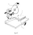
- FIG. 6 a is a schematic perspective view of a side of a rough block being trimmed with a miter slide on a table saw in accordance with an embodiment of the invention
- FIG. 6 b is a schematic perspective view of a working block being trimmed and squared with a miter saw, commonly known as a chop saw, in accordance with an embodiment of the invention
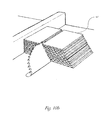
- FIG. 7 is a schematic perspective view illustrating the saturation of a rough block with an impregnating agent in accordance with an embodiment of the invention.
- FIG. 8 a is a schematic perspective view of a tile in which space defined by the flutes is filled, in accordance with an embodiment of the invention
- FIG. 8 b is a schematic detailed perspective view of the sectional cut depicted in the tile of FIG. 8 a , in accordance with an embodiment of the invention.
- FIG. 9 is a schematic perspective view of a working block in accordance with an embodiment of the invention.
- FIG. 10 a is a schematic perspective view of the cutting or segmenting of a working block into finished blocks in accordance with an embodiment of the invention
- FIG. 10 b is a schematic perspective view of a working block being cut or segmented into a rhombus-shaped finished block in accordance with an embodiment of the invention
- FIGS. 10 c and 10 d are perspective views of finished blocks having flute directions that are not perpendicular to a face of the block, in accordance with an embodiment of the invention.
- FIG. 11 a depicts schematic perspective views of finished blocks having different cross-sectional shapes related at least in part to an equilateral triangle in accordance with an embodiment of the invention
- FIG. 11 b depicts schematic perspective views of finished blocks having different cross-sectional shapes in accordance with an embodiment of the invention.
- FIG. 12 a is a schematic perspective view of a rhombus-shaped finished block that may be sliced into a tile component or may be joined together with two other small structures to form a combination finished block in accordance with an embodiment of the invention
- FIG. 12 b is a schematic perspective view of a hexagon-shaped combination finished block composed of three rhombi-shaped finished blocks in accordance with an embodiment of the invention
- FIG. 12 c - 12 d are schematic perspective views of finished blocks, each having a rigidifying component disposed on a face in accordance with an embodiment of the invention
- FIG. 12 e is a schematic perspective view of a composite finished block including a rigidifying component disposed between two finished block components in accordance with an embodiment of the invention
- FIG. 12 f is a schematic perspective view of three blocks being stacked together to form a single, larger block, in accordance with an embodiment of the invention.
- FIG. 13 is a schematic perspective view of a finished block being sliced up into tile components in accordance with an embodiment of the invention.
- FIGS. 14 a - 14 b , 15 a - 15 c , and 16 a - 16 b are photographs of different corrugated components that may be created in accordance with embodiments of the invention.
- FIG. 17 a is a schematic perspective view illustrating the step of pouring of a coating material into a mold in accordance with an embodiment of the invention
- FIG. 17 b is a schematic perspective view illustrating the process of forming an outer layer component by placing a corrugated component into a mold for plasticizing in accordance with an embodiment of the invention
- FIG. 18 a 1 is a schematic perspective view of an equilateral triangle-shaped tile including a rigidifying component and a singular multilayer outer layer component in accordance with an embodiment of the invention
- FIG. 18 a 2 is a schematic detailed perspective view of the sectional cut depicted in the tile of FIG. 18 a 1 , in accordance with an embodiment of the invention
- FIG. 18 b is a detailed perspective view of a tile having one multi-layered outer layer component in accordance with an embodiment of the invention.
- FIG. 18 c is a detailed perspective view of a tile having two multi-layered outer layer components in accordance with an embodiment of the invention.
- FIGS. 18 d - 18 f depict detailed cross-sectional views of a corrugated component during the creation of the outer layer component in accordance with an embodiment of the invention
- FIG. 19 a 1 is a schematic perspective view of a tile defined by two layers of corrugated components in accordance with an embodiment of the invention
- FIG. 19 a 2 is a schematic detailed perspective view of the rectangular section depicted in the tile of FIG. 19 a 1 , in accordance with an embodiment of the invention
- FIG. 19 b is a schematic partially cutaway perspective view of a tile defined by two layers of corrugated components separated from one another with an inner-tile spacer in accordance with an embodiment of the invention
- FIGS. 20 a - 20 b are plan and side views of a translucent tile defined by three rhombi-shaped tile components in accordance with an embodiment of the invention
- FIG. 20 c is a schematic perspective view of tubular materials placed inside a larger tube, in accordance with an embodiment of the invention.
- FIG. 20 d is a schematic top view of a circular tile including tubular materials, in accordance with an embodiment of the invention.
- FIG. 21 a is a schematic perspective view of a hexagonal tile including seven circular tile components, in accordance with an embodiment of the invention.
- FIG. 21 b is a schematic plan view of a circular tile or tile component, in accordance with an embodiment of the invention.
- FIG. 22 a is a schematic plan view of a rectangular tile defined by nested 30-60-90 triangles in accordance with an embodiment of the invention.
- FIG. 22 b is a schematic plan view of a surface covered by tiles having two nested shapes—equilateral triangles and equilateral hexagons—in accordance with an embodiment of the invention
- FIG. 22 c is a schematic plan view of a surface covered with equilateral triangle-shaped tiles in accordance with an embodiment of the invention.
- FIG. 23 a is a schematic perspective view of a cross-section of a tile component, shaped as an equilateral triangle, with a rigidifying structure incorporated within its corrugated structure in accordance with an embodiment of the invention
- FIGS. 23 b and 23 c are schematic perspective and enlarged detailed views of a rhombi-shaped tile defined by two equilateral triangle-shaped tile components, each one including a rigidifying component in accordance with an embodiment of the invention
- FIG. 23 d is a schematic plan view of a translucent tile defined by four tile components, two rhombi and two triangle-shaped tile components in accordance with an embodiment of the invention.
- FIG. 23 e 1 is a schematic perspective view of an equilateral triangle-shaped corrugated component being placed into a mold, with the borders of the mold not being removed, but rather being used as a rigidifying component of the tile, in accordance with an embodiment of the invention;
- FIG. 23 e 2 is a schematic perspective view of an equilateral triangle-shaped tile including the corrugated component and rigidifying component of FIG. 23 e 1 , in accordance with an embodiment of the invention
- FIG. 23 f is a schematic plan view of a surface covered with hexagon-shaped motif tiles incorporating the tile components of FIG. 23 a in accordance with an embodiment of the invention.
- FIG. 23 g is a schematic plan view of a surface covered with the hexagon-shaped tiles of FIG. 23 d in accordance with an embodiment of the invention.
- FIG. 24 is a graph illustrating the geometric relationship between any three identical circles abutting one another with vertices disposed along a common line;
- FIG. 25 a is a schematic plan view of a hexagonal tile motif defined by nine equilateral rhombi-shaped tile components in accordance with an embodiment of the invention
- FIG. 25 b is a schematic plan view of a hexagon-shaped tile motif defined by twelve equilateral rhombi-shaped tile components in accordance with an embodiment of the invention.
- FIG. 25 c - 25 d are plan views illustrating some alternative patterns that may be created by varying the orientation of the flutes in the tile motif illustrated in FIG. 25 b , in accordance with an embodiment of the invention.
- FIG. 25 e 1 is a plan view illustrating an alternative pattern that may be created by varying the orientation of the flutes in the tile motif illustrated in FIG. 25 b , in accordance with an embodiment of the invention
- FIG. 25 e 2 is a cross-sectional view through section A-A of the tile of FIG. 25 e 1 , in accordance with an embodiment of the invention
- FIG. 25 f is a schematic perspective view of another hexagonal tile having seven circular tile components, in accordance with an embodiment of the invention.
- FIG. 25 g is a schematic plan view of a circular tile or tile component, in accordance with an embodiment of the invention.
- FIG. 26 a is a diagram showing height H in several different tile component shapes that may be used to cover a surface with hexagons;
- FIG. 26 b is a schematic plan view of a hexagon-shaped motif including two sets of tile components that have surfaces areas related by the Golden Ratio, ⁇ ;
- FIG. 26 c is a diagram showing the geometry of finished blocks that may be used to define the tile components shown in FIG. 26 b;
- FIG. 27 a is a schematic plan view of a hexagon formed from two sets of tile components in which a ratio of a height Hi of an inner component to a height Ho of an outer component is the Golden Ratio, ⁇ ;
- FIG. 27 b is a diagram showing the geometry of finished blocks that may be used to define the tile components shown in FIG. 27 a;
- FIG. 28 a is a diagram illustrating the relationship between the Golden Ratio, ⁇ , and a surface covered with abutting circles.
- FIG. 28 b is a diagram illustrating circles that overlap to form hexagons.
- epoxy means any of various thermosetting copolymers that form tight cross-linked polymer structures characterized by toughness, strong adhesion, and low shrinkage.
- An epoxy is typically formed from a reaction of an epoxide resin with a polyamine hardener.
- epoxy resin is a resin consisting of monomers or short chain polymers with an epoxide group, i.e., a three-membered oxide ring, at either end.
- epoxy resins are polymers with a low degree of polymerization. They may be thermosetting resins that cross-link to form a three-dimensional nonmelting matrix.
- a curing agent hardener is generally used to achieve the proper degree of polymerization.
- glass transition temperature means the temperature at which an amorphous polymer, upon heating, transitions from a glass to a rubbery form.
- FIG. 1 a flow chart of a manufacturing process 100 includes processing cardboard to create a composite translucent material suitable for a variety of uses. A number of steps are performed to form a corrugated component, followed by the performance of steps to form a translucent corrugated tile having an outer layer component. Schematic diagrams illustrating the steps of the process of FIG. 1 are shown in FIG. 2 .
- the process 100 is used to manufacture a translucent building material out of corrugated cardboard or fiberboard in accordance with an embodiment of the invention.
- the process 100 includes the steps of providing a plurality of corrugated cardboard pieces (step 105 ) and sorting the cardboard by its thickness, color, size, and/or flute pattern (step 110 ).
- the sorted cardboard may be held together with, e.g., an adhesive, and the cardboard may be trimmed (step 115 ) to form a raw generally consistently-shaped material, i.e., a rough block 120 .
- the thickness of the rough block 120 may be dictated by downstream processing equipment, such as milling or cutting equipment, dimensional limitations.
- the process 100 may include saturating (step 125 ) the rough block 120 with an impregnating agent, such as a penetrating sealer, to form a working block 130 .
- a desired geometric shape may be determined (step 135 ), and the working block 130 may be milled along exterior dimensions and/or cut (step 140 ) to form a finished block 145 with the desired geometric shape.
- the finished block 145 may then be sliced (step 150 ) at a predetermined angle to the direction of the flutes of the cardboard pieces into slices, typically having a consistent thickness to create a plurality of substantially identical tile components 155 . At least a portion of the tile components 155 may be adhered together (step 157 ) to define a corrugated component 159 .
- a mold may be provided (step 160 ) and a coating material 162 , for example, a thin layer (e.g., 3 mm) of two-part epoxy, may be poured into the mold (step 165 ).
- the corrugated components 159 may be placed in the coating material 162 disposed in the mold (step 170 ) to create an outer layer component 172 on the corrugated components 159 and secure them together.
- the outer layer component 172 may include one or more layers of one or more coating materials 162 .
- the outer layer component 172 may also include materials other than coating material 162 and cardboard. Such materials may be transparent or translucent and adhered between or on top of the one or more layers of coating material 162 .
- the corrugated components 159 may be removed from the mold and excess coating material 162 may be trimmed (step 175 ) from the corrugated components 159 to form a translucent building material, e.g., a translucent corrugated tile 180 .
- Multiple translucent corrugated tiles 180 may be produced in this manner and, by using a suitable tailored geometry, tiles 180 may be used in various nested patterns to cover at least a portion of a surface 185 of any shape or size.
- the surface 185 may be, for example, a floor, a wall, a roof, a lighting installation, an architectural construction element, an architectural aesthetic element, and/or a solar panel.
- some tiles 180 may have several layers of corrugate.
- the process illustrated in FIG. 1 may be used to form a hexagonally shaped translucent tile 180 , as seen in FIG. 3 .
- the translucent tile 180 contains a pattern of flutes 400 , as shown in FIGS. 4 a - 4 c .
- a piece of corrugated cardboard contains a fluted corrugated sheet 405 and one or two linerboards 410 .
- the fluted corrugated sheet 405 is typically positioned between two linerboards 410 , and the shape of the fluted corrugated sheet 405 defines the flutes 400 .
- T c of the cardboard pieces By varying a thickness T c of the cardboard pieces, numerous patterns and various light textures may be attained.
- the providing step 105 may include gathering cardboard.
- any type of cardboard or corrugated material may be used, including old corrugated cardboard. Because old corrugated cardboard is an overly abundant raw material, it may be collected from a number of different sources. The cardboard may be gathered by, e.g., collecting cardboard locally house-to-house, as well as picked up in bulk from local businesses.
- the sorting step 110 may include sorting cardboard by, e.g., thickness, color, size, and flute pattern. Preferably, straight and dry pieces are selected. Further separation may include sorting and arranging the corrugated cardboard pieces by piece size and flute direction.
- the cardboard After the cardboard is gathered and sorted, it may be initially trimmed.
- the trimming may include cutting off the rough edges of the cardboard, as well as removing stitches, flaps, damaged areas, and other irregularities such as packaging tape or other foreign matter, and also cardboard that has been treated with any parrafinated waxes. These irregularities may interfere with the layering process.
- a rough block 120 is defined by holding together and trimming (step 115 ) a plurality of corrugated cardboard pieces 505 (also referred to herein as “cardboard sheets”).
- the cardboard pieces may be stacked face to face with each other, preferably (but not necessarily) with the flutes of each cardboard piece being aligned in a common direction 510 .
- having all flutes oriented in the same direction within a working block 130 may not be preferable.
- the flutes in adjacent pieces may be oriented at about 30 degrees, about 45 degrees, about 60 degrees, or about 90 degrees to one another.
- the flute orientation may alternate from one sheet to the next or vary in a sinusoidal or other pattern from one side of the stack to the other.
- the flute direction 510 is an important factor in the formation of the translucent material described herein.
- the cardboard pieces 505 may be individually cut such that a plurality of pieces have approximately the same dimensions. For example, a first cardboard sheet may be cut to an approximate size of the rough block 120 . Then the edges of the first sheet of cardboard may be cut at a desired angle 515 with respect to the direction 510 of the flutes 400 . In an embodiment of the invention, the angle is 90°; however, any angle may be used. Additional cardboard pieces 505 may be cut to align with the first sheet of cardboard, and the sheets of cardboard may be held together by any suitable method (e.g., adhesive, mechanical changes or fasteners, etc.).
- any suitable method e.g., adhesive, mechanical changes or fasteners, etc.
- a rigidifying component may be held next to or adhered to at least one of the plurality of corrugated cardboard pieces.
- the rigidifying component may be a top or bottom layer, or it may be disposed anywhere in the middle of a stack of cardboard pieces.
- the rigidifying component may be included to, for example, provide additional strength to the finished product, or facilitate its installation by providing an alternative surface, or it may be used as a design feature for either aesthetic purposes, or to act as a marker in further processing or in use.
- the rigidifying component may also be used to receive light (e.g., with photovoltaic materials), emit light (e.g., with light emitting diodes or other light sources, such as bioluminescent devices), and/or conduct heat or electricity.
- the rigidifying component may be formed from various materials other than cardboard, such as metal, plastics, rubber, wood, etc.
- the corrugated cardboard may be adhered together with an adhesive, i.e., thin layers of adhesive may be applied between sheets of cardboard, i.e., as a layer-to-layer adhesive, to stabilize the stack during further processing.
- an adhesive i.e., thin layers of adhesive may be applied between sheets of cardboard, i.e., as a layer-to-layer adhesive, to stabilize the stack during further processing.
- a cyanoacrylate adhesive is used, e.g., STICK FASTTM Instant CA Adhesive, available from Rockler, based in Medina, Minn.
- An adhesive may be selected to dissolve lignin pulp, a main component of cardboard, and to provide a strong bond to the impregnating agent, used in the following step. This instant adhesive bonds fibrous cardboard together, allowing the application of thin layers of adhesive.
- a different layer-to-layer adhesive may be used to attain a more flexible rough block 120 , i.e., an emulsion-based adhesive such as Lineco neutral pH acid-free adhesive available from Lineco, based in Holyoke, Mass.
- Emulsion-based adhesives may be very slightly diluted with water (e.g., about 3-7%), to facilitate the absorption of the adhesive by the cardboard deep into its fibers and to extend the working time of the adhesive, as well as to allow the creation of a thinner layer of the inter-layer adhesive.
- adhesives may be used, including wood glue, an aliphatic resin such as TITEBOND® II or TITEBOND® III, manufactured by Franklin International in Columbus Ohio, or an all-purpose glue, such as diluted GLUE-ALL®, manufactured by Elmer's Products, Inc., based in Columbus, Ohio.
- reducing the space between adhered cardboard sheets 505 by applying thin consistent layers of the adhesive may allow an impregnating agent that is subsequently added to the rough block 120 , as described below, to bond both to the adhesive and to the cardboard, thereby creating a bonding bridge, including the adhesive layer, between the cardboard layers.
- Applying thin, rather than thick, layers of adhesive may help prevent the formation of air pockets, etc. Such inconsistencies may compromise the integrity of the final surface or the structural integrity of the finished product.
- a light clamp 520 e.g., a weight
- the time interval between the applications of the clamp 520 preferably corresponds to the working time of the adhesive.
- the clamp 520 may be applied after about eight to about 15 seconds of adding cardboard pieces 505 to the stack of cardboard pieces 505 .
- the clamp 520 may be applied to the stack for at least about 30 seconds.
- the clamp 520 may be applied after about four to about five minutes of adding cardboard pieces 505 to the stack of cardboard pieces 505 .
- the clamp 520 may be applied for about 30 to about 60 minutes.
- the light clamp 520 may be, for example, a flat and heavy material, such as a thick piece of glass or a piece of metal.
- the clamp is large enough to cover the entire rough block 120 .
- the rough block 120 is formed upon a level surface 525 to help evenly distribute the pressure created by the clamp 520 , thereby facilitating the formation of a rough block 120 having approximate but consistent dimensions with uniform layers.
- one or more weights may be placed on top of the clamp to provide sufficient clamping pressure. Excessive weight may crush or damage the materials.
- the adhesive is preferably applied layer by layer.
- the adhesive may be applied by, e.g., squeezing a tube of adhesive by hand, preferably in a systematic pattern.
- Other methods for adhesive application include spraying the adhesive, applying the adhesive directly from a glue bottle, rolling the adhesive onto the cardboard, or brushing the adhesive onto the cardboard.
- adhesive may be applied in the form of a mist.
- the adhesive used in the layering process to form the rough block 120 is selected so that it does not interfere with the subsequent saturation step 125 .
- the adhesive is the same as the impregnating agent.
- the size of the cardboard pieces, i.e., length and width, that are used to form the rough block 120 may have a wide range, limited primarily by the available work space and/or storage space, e.g., volume capacity of the manufacturing facility. Thus, very small pieces, e.g., length and width of less than 1′′ or very large pieces, e.g., length and width of greater than 5 yards, may be used.
- Rough blocks 120 may be sized to improve process control, and to enhance the efficiency of the manufacturing process. Clamping large pieces, such as 5 yard ⁇ 5 yard pieces, requires handling a clamp of appropriate dimensions, making process control more challenging.
- rough blocks 120 may be mass-produced by slicing cardboard into the longest possible strips, e.g., 3 feet, 4 feet, or 6 feet, depending on the application, and then slicing the long rough blocks 120 into individual smaller rough blocks 120 .
- one or more layers may include a plurality of discrete pieces of corrugated cardboard in a predetermined or random pattern.
- the rough block 120 may be trimmed with a table saw 600 using a miter slide 605 on a table 610 along trimming lines.
- a miter saw 615 may be used to trim the rough block 120 .
- the edges of the rough block 120 may be trimmed such that all sides of the rough block 120 form right angles with each other.
- the rough block 120 may be trimmed with a miter saw 615 , commonly known as a chop saw.
- a suitable miter saw is a 12 inch compound miter saw, model number MS1250LZ, manufactured by Ridgid, a division of Emerson based in St. Louis, Mo.
- the process of trimming all sides of the rough block 120 at 90° in relation to each adjacent surface of the block may also be referred to as “squaring” the block. If the rough block 120 is not squared-off properly, slicing up the finished block 145 into consistently sized tile components 155 (discussed below) may be difficult.
- a thickness T r of the rough block is defined by the height of stacked layers of cardboard and corresponds to a height (H) of tile components 155 that are eventually made from the rough block 120 (see below).
- a maximum practical thickness of the rough block 120 is determined by the limitations of the equipment that is to be used to trim the rough block 120 into a finished block.
- a rough block 120 that is too thick to be cut by the equipment has a thickness T r that exceeds the maximum practical thickness that may be cut with that equipment.
- a rough block 120 having a thickness T r that is less than the maximum practical thickness may, in addition to being easier to cut, be desirable for aesthetic or structural reasons.
- a 10′′ JET® table saw 600 manufactured by Walter Meier Manufacturing Americas, based in LaVergne, Tenn., may be used; the use of this particular saw limits the thickness T r of the rough blocks 120 to a maximum of about 3.5′′, i.e., the distance that the blade extends above the table top. Further, if the miter slide 605 is utilized, the blade of the table saw 600 may cut a thickness of only about 3′′ because the thickness of the miter slide carriage may be about 0.5′′, thereby reducing the amount of the blade that is exposed. However, by mechanizing the process and using more powerful and industrial-sized equipment, thicker rough blocks 120 may be trimmed.
- the miter slide 605 may be used with the table saw 600 to accommodate cutting of blocks with smaller dimensions or to gain maximum consistency during the cross cutting, or slicing, of the blocks.
- a suitable miter slide 605 is, e.g., INCRA Miter Express, manufactured by Taylor Design Group, based in Dallas, Tex.
- the rough block 120 being trimmed and squared on a miter saw 615 may be seen in FIG. 6 b.
- the table saw 600 is typically used for cutting in a direction parallel to the flutes 400 .
- the miter slide 605 facilitates cutting across the flutes 400 . Cutting across the flutes may be necessary or desirable when, for example, slicing a finished block 145 into tile components 155 or forming a finished block 145 with a flute direction 510 that is not perpendicular to one of the faces of the block. Proper accessories for the equipment are preferably utilized.
- the rough block 120 may be cut on the table saw 600 without using the miter slide 605 . If the dimensions of the rough block 120 are short, then for the sake of safety, the miter slide 605 or miter saw 615 may be preferred for cutting the rough block 120 into an appropriate geometric shape.
- the miter saw 615 may be preferred when trimming or squaring blocks that are so short that trimming with the table saw 600 may be cumbersome. For example a RIDGID® miter saw may be capable of mitering 4 ′′ ⁇ 8′′ beams.
- the miter slide 605 clamps the rough block 120 to the carriage of the slide 605 as it is run through the table saw 600 . By clamping the rough block 120 to the carriage, the slide 605 prevents kick-back on the table saw 600 and thereby may increase safety.
- the use of the miter slide 605 may provide other benefits, e.g., helping to achieve machining consistency, especially when many precision cuts have to be made. It is also important for the table saw 600 to be electrically grounded, as cutting of the rough blocks 120 may create excess static electricity, which is preferably taken into consideration in high volume production.
- the rough block 120 is saturated with an impregnating agent 705 .
- “saturate” means to impregnate with an impregnating agent the fluted corrugated sheets 405 and the linerboards 410 of the corrugated cardboard.
- the rough block 120 may preferably be stood upright on a protective layer 710 disposed on a level surface with the flutes 400 having a direction 510 aligned with vertical, i.e., approximately perpendicular to the level surface.
- the protective layer 710 is preferably formed from an inert material that does not adhere to the impregnating agent 705 , e.g., a thin sheet of acrylic, lexon glass, or any other material with a waxy surface.
- an inert material that does not adhere to the impregnating agent 705 , e.g., a thin sheet of acrylic, lexon glass, or any other material with a waxy surface.
- a mold is formed from a material to which cardboard/impregnating agent may stick, e.g. metal
- spraying the mold with an appropriate release agent, e.g., silicone spray may help ensure that the rough block 120 may be easily extracted from the mold.
- GRAFIX® clear acetate, 0.005′′ thickness may be used.
- the use of an inert material helps ensure that the working block 130 may be easily removed from the level surface after the impregnating agent 705 has cured.
- a border 720 may be disposed on the protective layer to help prevent run-off of excess impregnating agent 705 .
- the border 720 may be, e.g., a frame made from any material having a sufficient thickness to contain the spreading of excess impregnating agent 705 .
- An adhesive tape 725 may be wrapped around the rough block 120 to reduce run-off of the impregnating agent 705 and to reduce any clean-up that may be required.
- a suitable adhesive tape 725 may be, for example, a clear polyurethane tape, e.g., SCOTCH® clear packaging tape manufactured by 3M, based in St. Paul, Minn., or a painter's masking tape such as SCOTCH-BLUETM painter's tape manufactured by 3M.
- the impregnating agent 705 may be introduced into the flutes 400 of the rough block 120 to fully saturate the rough block 120 .
- the saturation of the rough block 120 may be achieved by various methods.
- the impregnating agent 705 may be poured from a container 730 into the rough block 120 at atmospheric pressure, using gravity as the force to propel the impregnating agent through the rough block 120 .
- the rough block 120 may also be submerged into a bath of impregnating agent 705 and placed onto a level surface to allow excess agent to drain.
- the saturation step 125 may use pressure, in addition to gravity, to force the impregnating agent 705 down through the flutes 400 .
- Pressure may be applied by blowing air from a compressor via a hose into the flutes 400 , forcing the impregnating agent 705 therethrough.
- the use of vacuum e.g., partial vacuum, typically accelerates the saturation process.
- a vacuum may be applied to the flutes 400 at an opposing end of the rough block 120 to help draw the impregnating agent 705 through the rough block 120 .
- Saturation may be improved by, e.g., diluting the impregnating agent 705 to reduce its viscosity and facilitate its flow and wetting of the cardboard.
- impregnating agent 705 may be introduced by dipping the rough block 120 into a bath of impregnating agent 705 and rotating the rough block 120 , as needed, to saturate the entire block. Centrifugal processes may also be used.
- a suitable impregnating agent 705 is a penetrating sealer that is a three-dimensional polymer capable of bonding with a coating material 162 , as discussed below.
- the impregnating agent 705 is mold-resistant, has a low viscosity, is not flammable, and is a three-dimensional polymer network with step growth possibilities.
- a three-dimensional polymer network with step growth possibilities allows for the outer layer component 172 (discussed below) to adhere without machining or otherwise preparing the surface of a corrugated component 159 (discussed below), while creating a covalent bond between the corrugated and outer layer components 172 .
- the viscosity of the impregnating agent 705 may be a limiting factor in the practical length of the rough block 120 that may be used.
- the impregnating agent 705 preferably fully saturates the rough block 120 , and is able to travel at least halfway through the rough block 120 from opposing sides.
- a desired viscosity of the impregnating agent 705 may be attained by the use of pressure and/or vacuum, i.e., a thixotropic fluid, may be desired, to enable saturation of rough blocks 120 with various dimensions with the same impregnating agent 705 .
- a suitable impregnating agent 705 may be a two-part epoxy including a bisphenol A/epichlorohydrin-based epoxy resin and an aliphatic amine adduct hardener, such as 103-LVX EPO-STEEL epoxy low viscosity epoxy resin and part 2 hardener, manufactured by FASCO Unlimited of Hialeah, Fla.
- the material safety data sheet (MSDS) for this two-part epoxy i.e., Bisphenol A/Epichlorohydrin Based Epoxy Resin; 103, 103-LVX, 103-LVX-EP EPO-STEEL—PART 1, 103-LVX-SS; MSDS; Fasco Unlimited of Hialeah, Inc.: Hialeah, Fla., Jun. 4, 1993, is hereby incorporated by reference in its entirety.
- the hardener for this epoxy is an aliphatic amine adduct.
- This two-part epoxy may be thinned with acetone to achieve very low viscosity, thereby ensuring good saturation. It may also be flash cured by raising the surrounding temperature to, e.g., 120° F. Flash curing may increase the time-efficiency of a production process by accelerating the rate of curing.
- Another suitable two-part epoxy that may be used as an impregnating agent 705 includes a first part that is an epoxy resin including bisphenol A/epicholorohydrin resin and aliphatic and aromatic glycidyl ethers, such as ENVIROTEX LITE Resin, and a second part that is a hardener, e.g., a clear epoxy hardener containing nonyl phenol, n-aminoethylpiperzine, and polyoxyalkyleneamines, such as ENVIROTEX LITE Hardener, both manufactured by Environmental Technology, Inc., based in Fields Landing, Calif. This material allows for the formation of relatively more flexible corrugated components 159 .
- an epoxy resin including bisphenol A/epicholorohydrin resin and aliphatic and aromatic glycidyl ethers such as ENVIROTEX LITE Resin
- a hardener e.g., a clear epoxy hardener containing nonyl phenol, n
- the MSDSs for this two-part epoxy i.e., Envirotex Lite—Resin ; MSDS; Environmental Technology, Inc.: Fields Landing, Calif., Oct. 6, 2008; Envirotex Hardener ; MSDS; Environmental Technology, Inc.: Fields Landing, Calif., Oct. 6, 2008, are hereby incorporated by reference in their entireties.
- the ENVIROTEX LITE system is preferably used in non-structural interior applications, such as lights or architectural aesthetic detailing, because, in contrast to various other two-part epoxy systems, the ENVIROTEX LITE system may react with water.
- WEST SYSTEM® 105TM Epoxy Resin including bisphenol-A type epoxy resin, benzyl alcohol, bisphenol-F type epoxy resin and ethylene glycol monobutyl ether
- WEST SYSTEM® 205TM Fast Hardener polyethylenepolyamine, reaction products of TETA with phenol/formaldehyde, triethylenetetramine (TETA), hydroxybenzene, reaction products of TETA and propylene oxide, and tetrathylenepentamine (TEPA)] or the WEST SYSTEM® 209TM Extra Slow Hardener (TOFA, reaction product with TEPA, polycycloaliphatic amine, polyoxypropylenediamine, isophorone diamine, 4,4′-methylenebiscyclohexane, tetraethylenepentamine, benzene-1
- TOFA Extra Slow Hardener
- the MSDSs for these materials i.e., Bisphenol A Based Epoxy Resin; 105; MSDS; West System, Inc.: Bay City, Mich., Jan. 3, 2008; Modified Polyamine; 209; MSDS; West System, Inc.: Bay City, Mich., Jan. 3, 2008; Modified Aliphatic Polyamine; 205; MSDS; West System, Inc.: Bay City, Mich., Jan. 3, 2005, are hereby incorporated by reference in their entireties.
- Bisphenol F Diglycidyl Ether ; NANOPDX F 520; MSDS; Hanse Chemie USA, Inc.: Hilton Head Island, S.C., Oct. 27, 2005 is also hereby incorporated by reference in its entirety.
- Suitable impregnating agents 705 include, for example, a penetrating sealer such as polyaspartic polyurea, silicates, siliconates, plant-based resins, and combinations thereof.
- a penetrating sealer such as polyaspartic polyurea, silicates, siliconates, plant-based resins, and combinations thereof.
- An example of a polyaspartic polyurea is Corian® commercial solid surface, available from DuPont Surfaces, Wilmington, Del.
- Suitable penetrating sealers e.g., silicates or siliconates
- Polyaspartics are based on the reaction of an aliphatic polyisocyanate and a polyaspartic ester, which is an aliphatic diamine. Polyaspartics are also two-part systems, but typically have much quicker reaction times than two-part epoxies; their application, therefore, may require special spray equipment. Polyaspartics may also be used to form the outer layer component.
- the saturation step 125 may be repeated until the rough block 120 is sufficiently saturated, i.e., the impregnating agent may be applied multiple times to the rough block 120 to achieve proper epoxination.
- the rough block 120 is fully saturated by the impregnating agent throughout, with no voids anywhere in the rough block 120 or air pockets, e.g., between cardboard layers.
- full saturation means that substantially all of the cardboard, i.e., all of the flutes 400 and linerboards 410 in the rough block 120 are saturated with the impregnating agent, but the spaces defined by the flutes 400 are not filled.
- the spaces defined by the flutes may be at least partially filled. This oversaturation may compromise the consistency of the tiles 180 as well as interfere with the slicing of the finished block 145 into tiles 180 and tile components 155 (discussed below).
- extra impregnating agent that accumulates near the bottom of the rough block may be used to form an outer layer component (described below). For example, when excess impregnating agent is added during the saturation step, it may tend to pool up near the bottom of the cardboard materials. Once this layer of extra impregnating agent dries or cures, it forms an outer layer on the cardboard. In this way, the impregnating agent may be used to both saturate the cardboard and create the outer layer component.
- portions of the rough block 120 saturated by the impregnating agent typically become darker than surrounding, non-saturated areas. Discoloration of the working block 130 by the impregnating agent enables one to determine the degree of saturation. For example, if lighter, non-saturated areas are visible, additional impregnating agent may be added until the rough block 120 is uniformly darker and fully saturated. Prior to the introduction of the impregnating agent, rough blocks 120 typically have a generally uniform color.
- the working block 130 may be referred to as the working block 130 .
- the desired level of saturation may vary depending on the intended application. Over-saturation occurs when spaces defined by the flutes 400 get fully or partially filled with excess impregnating agent. Over-saturation is generally avoided, as cutting cured epoxy may dull cutting tool blades, especially ones designed primarily for wood cutting. Alternatively, a specialized blade designed for cutting hard laminates and plastics may be used with the table saw 600 . For example, a 10′′ coated solid surface blade, manufactured by Freud in Italy, may be used.
- Another suitable blade is Freud LU94M010 10-Inch 80 Tooth MTCG Plexiglass and Plastic Cutting Saw Blade with 5 ⁇ 8-inch arbor. These are specialty blades that may be used when cutting epoxinated blocks and/or tiles 180 that have an outer layer component 172 made from, for example, hardened epoxy and/or plexiglass. These fine-toothed blades are also suitable for cutting cardboard, even if it is not epoxinated, because the blades are designed to cut off little pieces as the blades go through the material, thereby helping prevent cardboard from being shredded.
- FIG. 8 a diagram illustrating a detailed view of a tile component 155 with spaces 800 between the fluted sheet 405 and liner boards filled with an expanding polymer may be seen. This may be achieved by, e.g., using an impregnating agent 705 that is an expanding polymer, such as BAYSEALTM OC open-cell spray polyurethane foam insulation or BAYSEALTM CC closed-cell spray polyurethane foam insulation, manufactured by Bayer Material Science AG, based in Leverkusen, Germany. This product is typically used as a green, VOC-free, non-flammable wall insulation.
- an impregnating agent 705 that is an expanding polymer, such as BAYSEALTM OC open-cell spray polyurethane foam insulation or BAYSEALTM CC closed-cell spray polyurethane foam insulation, manufactured by Bayer Material Science AG, based in Leverkusen, Germany. This product is typically used as a green, VOC-free, non-flammable wall insulation.
- a first component of an expanding polymer product may be applied by dipping a working block into a bath of the first component while maintaining the flute direction 510 approximately perpendicular to the surface of the bath.
- a second component of the expanding polymer product may then be poured into the spaces 800 from the top of the block.
- the product expands through the block to fill the spaces 800 between the fluted sheet 405 and liner boards. Once the spaces 800 are filled, then the corrugated structure attains greater rigidity, with potentially lower translucency.
- the sponge-like absorbent qualities of cardboard are utilized. Because of the extremely high permeance values of the corrugated cardboard component, absorption of an appropriate impregnating agent creates a continuous bond on a molecular level. Such bond may also be referred to as a covalent bond.
- a working block 130 includes a number of cardboard pieces of the same size, saturated by an impregnating agent.
- the flutes in the cardboard extend from one face to an opposing face and are typically aligned in the same direction 510 .
- each face of the working block 130 is parallel to an opposing face, and perpendicular to all adjacent sides of the working block 130 .
- Light may travel through flutes connecting opposing end faces.
- a working block 130 may be cut 140 by, e.g., using a combination of a miter saw and a table saw to form finished blocks 145 having appropriate geometric shapes for the intended application.
- Tile components 155 may subsequently be prepared from the finished block 145 with dimensions and thickness of any desired size.
- a possible cutting schedule of a working block 130 may be seen in FIG. 10 a , in which finished blocks 145 having cross-sections in the shape of a triangle, a rhombus, and a trapezoid are formed from a single working block 130 .
- the embodiment in FIG. 10 b shows a working block 130 being cut into a rhombus and a remainder shape, but any number of different shapes may be derived from a single working block 130 .
- a surface 1010 of the finished block 145 is intersected by the flutes 400 .
- the flute direction 510 and the surface 1010 of the finished block 145 define an angle ⁇ .
- the angle ⁇ is 90 degrees.
- the angle ⁇ is less than 90 degrees.
- the magnitude of the angle ⁇ may be determined at one or more cutting and trimming steps within the process 100 .
- the angle ⁇ may be defined by trimming one or more cardboard sheets at a desired angle with respect to the flute direction 510 prior to holding and trimming (step 115 ) the sheets to form the rough block 120 .
- the angle ⁇ may be defined by trimming (step 115 ) a stack of cardboard sheets at a desired angle to form the rough block 120 .
- the angle ⁇ may be defined by milling or cutting (step 140 ) the working block 130 at a desired angle to form the finished block 145 .
- the working block 130 may be milled and/or cut 135 into finished blocks 145 having appropriate prismatic, contoured, or other geometric shapes for the intended application.
- FIGS. 11 a and 11 b show a variety of shapes that may be derived from a working block 130 , including finished blocks 145 having cross-sections in the shape of a triangle, a square, a rectangle, a pentagon, a hexagon and a circle.
- FIG. 12 a shows a schematic diagram of a rhombus shaped finished block 145 .
- a finished combo-block 1200 may undergo additional saturation (step 125 ) with impregnating agent 705 . It may be preferable to use the same impregnating agent 705 as was used to saturate the individual working blocks in order to achieve complete saturation. In other embodiments, it may be preferable to use a different impregnating agent 705 to, for example, create desirable textures or patterns within a translucent tile 180 .
- the adhesive used to form the finished combo-block 1200 from the finished blocks 145 may be, for example, a cyanoacrylate adhesive, such as STICK FASTTM Instant CA Adhesive (available from Rockler, Medina, Minn.), or SUPER 77® spray adhesive (manufactured by 3M).
- a cyanoacrylate adhesive such as STICK FASTTM Instant CA Adhesive (available from Rockler, Medina, Minn.), or SUPER 77® spray adhesive (manufactured by 3M).
- finished blocks 145 may include a rigidifying component 1205 disposed upon a face.
- the rigidifying component 1205 may be, for example, part of the mold 1700 .
- a composite finished block 1210 may include the rigidifying component 1205 disposed between two finished block 145 components.
- the rigidifying component 1205 is generally a sheet or a portion thereof made of a material that is stiffer than corrugated cardboard, such as plastic, carbon fiber, wood, metal, glass, and/or non-corrugated cardboard. Use of the rigidifying component 1205 may therefore improve the structural rigidity of the finished block 145 , tile component 155 , and/or tile 180 .
- finished blocks 145 that are thicker than the maximum practical thickness (i.e., the thickness that may be cut with available machining equipment) may, in effect, be created by stacking two or more blocks together. These stacked arrangements allow larger tile components 155 to be created during the slicing step 150 . Larger rough blocks 120 and/or larger working blocks 130 may also be created by stacking blocks in this manner, for example to create a block having a thickness of 3T r from three blocks each with a thickness of T r .
- a finished block 145 is sliced (step 150 ) at a predetermined angle to the direction of the flutes into slices having a consistent thickness to define a plurality of uniform tile components 155 .
- the finished block 145 may be sliced into tile components 155 of the same or different thicknesses.
- the tile components 155 are produced directly from the working block 130 rather than from the finished block 145 .
- the working block 130 may not be necessary to machine the working block 130 into a finished block 145 before it is sliced into the tile components 155 .
- the working block 130 may be processed into tile components 155 using the same methods described herein for the finished block 145 .
- this approach may be more efficient.
- the tile components 155 may be of better quality (e.g., have more precisely defined edges) when they are produced from the finished block 145 rather than from the working block 130 .
- Improper expoxination of the rough block 120 may become apparent during the slicing (step 150 ) of the finished block 145 into tile components 155 , e.g., a blade may not cut an underepoxinated finished block 145 , but rather rip the cardboard of the finished block 145 , creating a rough cut and partially blocking spaces defined by the flutes.
- the slicing may preferably be temporarily interrupted and the saturation 120 step repeated with the underepoxinated finished block 145 . Once the finished block 145 has cured, the slicing into tile components 155 may resume.
- Clean cuts and sharp edges defined by the flutes may be preferable in some embodiments, since a clean cut intersecting the flutes leaves the flutes fully open, improving their visual appearance for various applications. Having open spaces 800 between the flutes 400 also allows for complete filling of these spaces 800 , which may be preferred in some embodiments.
- the corrugated component 159 may be produced by arranging one or more tile components 155 in a desired geometry and holding them together along respective abutting edges. A plurality of tile components 155 may be adhered together with, e.g., a cyanoacrylate adhesive such as STICK FASTTM Instant CA adhesive, available from Rockler, based in Medina, Minn., to form a corrugated component 159 having a geometric pattern.
- the corrugated component 159 may include a single tile component 155 .
- One or more tile components 155 may have one or more sides covered with the outer layer component 172 .
- the outer layer component 172 may be created as follows. The step in which the outer layer component 172 is created may be referred to as “texturization” of the tile component 155 . The texturization of the tile component 155 turns the somewhat pliable delicate material of the tile component 155 into a rigid translucent sealed tile 175 .
- a mold 1700 may be set up on a level surface 1705 to serve as a receptacle for the coating material 162 .
- the mold 1700 may be covered by a protective layer 1710 composed of, e.g., LEXAN® or a material with similar qualities, i.e., having a waxy surface, to facilitate easy removal of the tile component 155 from the mold 1700 .
- the level surface 1705 is preferred for this step because of the self-leveling characteristics of the coating material 162 .
- At least a portion of the corrugated component 159 is placed into the coating material 162 in the mold 1700 .
- the coating material 162 may be cured to create the outer layer component 172 having a texture of the mold 1700 .
- the corrugated component 159 , with the cured coating material 162 may be removed from the mold, and the excess coating material 162 may be removed to create a translucent tile 180 .
- the coating material 162 may cure by, for example, polymerization, and the outer layer component 172 may be a cross-linked polymer. Curing may be accelerated by flash curing, e.g., exposing the coating material 162 to heat. For example, the corrugated component 159 and coating material 162 may be heated together to about 125° F. in an oven. Flash curing is preferably used with coating materials that cure by condensation polymerization, e.g., 103-LVX EPO-STEEL epoxy resin.
- Proper placement of the corrugated material in the mold 1700 is relevant. For example, it may be desirable to place a light clamp or weight on top of the corrugated component 159 for the duration of the cure.
- the weight may facilitate the penetration of the coating material 162 into the corrugated component 159 so that the outer layer component 172 extends into interior portions of the corrugated component 159 .
- the weight may also prevent the corrugated component 159 from warping due to, for example, humidity.
- a warped corrugated component 159 may be unusable as a building material, but may be suitable for other aesthetic purposes.
- This texturization process may be repeated on the same face to form a tile 180 with a multi-layered outer component 1800 .
- a detailed view of a tile 180 with a multi-layer outer component may be seen in FIGS. 18 a 1 - 18 a 2 and FIGS. 18 b - 18 c .
- This process may be repeated on an opposite face of the same tile 180 to form a second outer layer component 172 ′.
- a detailed view of a tile 180 with two outer-layer components may be seen in FIG. 18 c .
- a layer of air or other insulating gas or material is placed between two outer layer components to increase the thermal resistance of the tile 180 .
- a solar panel may be placed between two outer layer components. Multiple outer layer components may make the tile 180 more water impermeable.
- FIGS. 18 d - 18 f depict detailed cross-sectional views of the corrugated component 159 during the creation of the outer layer component 172 .
- the protective layer 1710 prevents the corrugated component 159 from adhering to the mold 1700 .
- the protective layer 1710 is positioned between the corrugated component 159 and the mold 1700 .
- the protective layer 1710 may be positioned between the corrugated component 159 and a side wall 1810 of the mold 1700 .
- the protective layer 1710 prevents the coating material 162 from adhering the corrugated component 159 to the mold side wall 1810 .
- the mold side wall 1810 may be made of, for example, any rigid material, such as carbon fiber, wood, cardboard, metal, and/or glass. In the depicted embodiment, the coating material 162 penetrates into interior portions of the corrugated component 159 .
- the coating material 162 is used to attach the mold 1700 and/or mold side wall 1810 to the corrugated component 159 . This may be achieved, for example, by removing the protective layer 1710 so that the corrugated component 159 is placed directly onto the mold 1700 . Without the protective layer 1710 , the coating material 162 is able to reach the mold and, depending on the mold materials used, may adhere the mold 1700 to the corrugated component 159 . Molds 1700 made of, for example, glass, plastic, quartz, and/or photovoltaic materials may be attached to the corrugated component 159 in this manner.
- the mold 1700 may be cut or trimmed to a desired shape and size using, for example, a glass cutter or a water pressure saw.
- the mold 1700 may be attached to the working block 130 with the impregnating agent 705 during the saturation step 125 .
- the rigidifying component 1205 may be adhered to the corrugated component 159 before, during, or after the creation of the outer layer component 172 .
- the rigidifying component 1205 and the corrugated component 159 may be adhered together with an adhesive and then placed into the coating material 162 together.
- the coating material 162 may act alone as an adhesive between the rigidifying component 1205 and the corrugated component 159 .
- the rigidifying component 1205 may be adhered to the corrugated component 159 such that the rigidifying component 1205 protrudes a distance T p from the surface of the corrugated component 159 .
- the resulting thickness of the outer layer component 172 above the corrugated component 159 is approximately T p .
- the corrugated component 159 and the rigidifying component 1205 may be placed next to the mold side wall 1810 .
- the mold side wall 1810 which may or may not become part of the tile 180 , may help contain the coating material 162 during the creation of the outer layer component 172 .
- the mold side wall 1810 is adhered to the corrugated component 159 , with an adhesive and/or with the coating material 162 , and becomes a rigidifying component 1205 in the tile 180 .
- the mold side wall 1810 is not adhered to the corrugated component 159 and the mold side wall 1810 and corrugated component 159 are separated after the outer layer component 172 has been formed.
- two layers of corrugated components 159 may be laminated to one another face-to-face to define a translucent tile 180 . This allows a surface 185 to be covered with a multi-layered corrugated structure.
- the two layers of corrugated components 159 may be adhered together after the outer layer component 172 has been formed on each corrugated component 159 .
- the outer layer component 172 provides a uniform surface area suitable for proper adhesion of the two layers.
- the two layers of corrugated components 159 may or may not have matching geometric patterns and/or flute patterns.
- Forming a tile 180 with multiple corrugated layers may provide additional strength and may enable multidimensional control of light flow through the tile 180 .
- a varying flute direction within the layers of the tile 180 may achieve a desired path for the light to flow through the tile 180 .
- a roof, window, or wall tile may prevent the passage of light from one source or direction and allow the passage of light from another source or direction.
- a light source e.g., a light emitting diode or luminescent film layer
- an inter-tile spacer 1900 defines a cavity between the two surfaces of two corrugated components 159 .
- a detailed view of a translucent tile 180 defined by two layers of corrugated components 159 separated by the inner-tile spacer 1900 may be seen in FIG. 19 b .
- the depth of the cavity may vary with the thickness T s of the inter-tile spacer 1900 .
- the hollow space created by the spacer may be used for a specific function, e.g., for the insertion of a light source, a photovoltaic component, a fluid or gas, etc.
- the inter-tile spacer 1900 may be made of any material that provides the desired mechanical properties for the particular application.
- the inter-tile spacer 1900 may be made of carbon fiber, wood, metal, glass, and/or cardboard.
- the inter-tile spacer 1900 may also be made of materials that provide a desired conductivity for the transfer of heat and/or electricity between the two corrugated components 159 .
- the inter-tile spacer 1900 may be made of a conductive material, such as metal, so that heat and/or electricity may easily flow between the two corrugated components 159 .
- the inter-tile spacer 1900 fills the space between the two corrugated components 159 .
- the inter-tile spacer ( 1900 and/or the hollow space may provide a thermal or electrical break.
- the coating material 162 may be any material that provides a tile surface with desirable characteristics. Examples of characteristics that may be desirable, depending on the application, may be transparency, durability, recyclability, high tensile strength, shear strength, impact resistance, non-slip texture, and/or flexibility. In some embodiments, the coating material 162 is preferably a suitable matrix material for a function-specific additive, e.g., photovoltaic nanopolymers. Some exemplary materials that may be used as coating materials include thermosetting acrylics, thermosetting epoxies, polyamides, photocurable acrylics, polyaspartic polyurea, and combinations thereof.
- Thermosetting epoxies may be one-part or two-part epoxies.
- the first part of the two-part epoxy is a resin and the second part of the two-part epoxy is a hardener.
- the resin includes or is a bisphenol-A based epoxy resin.
- the first part of the epoxy may include, in addition, benzyl alcohol, bisphenol-F type epoxy resin, and ethylene glycol monobutyl ether.
- the hardener of the second part of the two-part epoxy may include a modified polyamine.
- a suitable modified polyamine may include polyoxypropylenediamine, reaction products of isophorone diamine with phenmol/formaldehyde, isophoronediamine, reaction products of benzene-1,3-dimethaneamine with hydroxybenzene and formaldehyde, hydroxybenzene, and m-Xylene diamine.
- a commercially available product in accordance with this embodiment is WEST SYSTEM® 105TM Epoxy Resin in combination with a hardener, such as WEST SYSTEM® 207TM Special Coating Hardener (polyoxypropylenediamine, reaction products of isophorone diamine with phenol/formaldehyde, isophoronediamine, reaction products of benzene-1,3-dimethaneamine with hydroxybenzene and formaldehyde, hydroxybenzene, and m-Xylene diamine), manufactured by West System Inc., Bay City Mich.; the MSDSs for these materials, i.e., Bisphenol A Based Epoxy Resin; 105; West System, Inc.: Bay City, Mich., Jan.
- a hardener such as WEST SYSTEM® 207TM Special Coating Hardener (polyoxypropylenediamine, reaction products of isophorone diamine with phenol/formaldehyde, isophoronediamine, reaction products of benzen
- WEST SYSTEM® 207TM Special Coating Hardener is especially suitable for attaining a strong surface, at least because it has a high shear strength.
- Epoxies with low pliability typically have a high percentage of solids and a low percentage of volatile compounds, as the latter contribute to pliability.
- a tile 180 with a relatively more pliable outer layer component 172 may be used, because the tile 180 is unlikely to be exposed to high temperatures and, therefore, the risk of undesirable shifting movement of the tile surface is relatively low.
- An exemplary epoxy with low pliability is polyaspartic polyurea coating, which is 100% solids with no volatile components.
- the resin includes a bisphenol-A/epichlorohydrin resin
- the first part of the epoxy further includes aliphatic and aromatic glycidyl ethers.
- the hardener of the second part of the two-part epoxy may be a clear epoxy hardener including nonylphenol, as well as polyoxyalkyleneamines and n-aminoethylpiperazine.
- a commercially available product in accordance with this preferred embodiment is ENVIROTEX LITE—resin and ENVIROTEX LITE—hardener, available from Environmental Technology, Inc., based in Fields Landing, Calif.
- MSDSs for these products i.e., Envirotex Lite—Resin ; MSDS; Environmental Technology, Inc.: Fields Landing, Calif., Oct. 6, 2008; Envirotex Hardener ; MSDS; Environmental Technology, Inc.: Fields Landing, Calif., Oct. 6, 2008, are hereby incorporated by reference in their entireties.
- Suitable polyamides include nylon-6,6 and nylon-6.
- the coating material 162 includes a polyamide as well as an additive.
- the additive may be, for example, a heat stabilizer, a light stabilizer, a lubricant, a plasticizer, a pigment, a nucleating agent, a flame retardant, and/or a reinforcing filler.
- heat stabilizers may be, for example, copper salts, phosphoric acid esters, mercaptobenzothiazole, mercaptobenzimidazole, and/or phenyl- ⁇ -naphthyl-amine.
- Light stabilizers may be carbon black and/or various phenolic materials.
- Self-lubricating grades of nylon may include lubricants such as molybdenum disulfide (0.2%) and graphite (1%).
- Plasticizers such as a blend of o- and p-toluene ethyl sulfonamide, may be used to lower the melting point of the polyamide and to improve toughness and flexibility, especially at low temperatures.
- Suitable nucleating agents include silica and phosphorous compounds.
- Flame retardants may include various halogen compounds synergized by zinc oxide or zinc borate and phosphorous compounds.
- An example of a suitable flame retardant is DISFLAMOLL DPK, i.e., diphenyl cresyl phosphate, manufactured by Bayer AG, based in Leverkusen, Germany. Heat stabilizers may also be suitable for use as impregnating agents.
- Reinforcing fillers may be, for example, glass fibers, glass beads, glass powder, and/or quartz.
- the thermosetting epoxy may be a laminating epoxy or a surface-coating epoxy.
- it may include a base and a converter.
- the base may include aliphatic polyamine, propoxyethanol, and acetic acid crystalline silica
- the converter may be an epoxy resin that is a reaction product of epichlorohydrin and bisphenol-A, aromatic hydrocarbon, and phenylethane.
- a material with this composition is DURA-PDXY, available from Duran Industrial Flooring, based in Minneapolis, Minn.
- the MSDS for DURA-PDXY i.e., AQUAGRIP 2600 Converter ; MSDS; U.S. Coatings: St. Louis, Mo., Nov. 26, 2007, is hereby incorporated by reference in its entirety.
- Dura-Poxy is a surface-coating epoxy that may be applied with a thickness as great as 10 mils.
- Another thermosetting epoxy may be a two-party epoxy including a waterborne epoxy, e.g., (i) a first part that is a combination of titanium dioxide, polyethylene, and polyamine isopropyl alcohol and (ii) a second part that includes bisphenol A diglycidyl ether resin.
- An exemplary material with this composition is DURASEAL 2489, a waterborne two-part concrete surface coating epoxy available from Pro-Chem, Inc., based in Alpharetta, Ga.
- thermosetting epoxy that is a laminating epoxy is 103-LVX EPO-STEEL epoxy resin.
- the coating material 162 may have a high percentage of solids, e.g., up to 100%.
- a coating material 162 that has a high percentage of solids has a low percentage of volatile organic compounds (“VOCs”) and volatile inorganic compounds (“VICs”) and, therefore, has a relatively low toxin concentration.
- VOCs volatile organic compounds
- VICs volatile inorganic compounds
- An example of a coating material 162 having a high percentage of solids is DURA-PDXY Heavy Body manufactured by Durall Industrial Flooring, based in Minneapolis, Minn.
- the coating material 162 may include functional materials mixed therein, such as nanoparticles.
- the coating material 162 may have a high glass transition temperature T g , e.g., at least 115° C.
- a material with a high glass transition temperature may provide stability that may be beneficial in the building industry.
- a material with a T g of room temperature is a plastic, and a T g below room temperature is a rubber.
- a suitable product with sufficiently high T g may be, for example, a styrene-grafted polyphenelene oxide (“PPO”) such as XYRONTM, available from Asahi Kasei Chemicals based in Japan, that has a T g of 208° C.
- PPO styrene-grafted polyphenelene oxide
- the coating material 162 may have a relatively low glass transition temperature, e.g., poly-silafluoroalkyleneoligosiloxanes, a class of fluoroelastomers.
- This material after crosslinking, has good flexibility at low temperature with a glass transition temperature below ⁇ 45° C. and good thermooxidative stability, over 250° C.
- a material with a low glass transition temperature tends to be more flexible at room temperature, a characteristic that may be desirable in certain applications.
- the surface texture of the tiles 180 may be controlled by the texture of the protective layer of the mold.
- the texture of the outer layer component 172 is similar to the texture of the mold in which it is formed. For example using a glossy smooth mold surface such as plexiglass with a glossy shine may give the outer layer component 172 —and the respective tile 180 —a transparent quality similar to that of glass. On the other hand, using a matt mold surface typically results in a matt outer layer component 172 .
- the outer layer component 172 may include several different layers. For example, it may include a DURA PDXY layer, with a functional layer attached thereto with an appropriate laminating material.
- the laminating material may be, e.g., 103-LVX EPO-STEEL epoxy resin, a system suitable for laminating a material such as glass, a polyamide thin film, or a photovoltaic layer.
- the outer layer component 172 may provide a waterproof layer and may also add structural integrity to the tile 180 .
- the outer layer component 172 may provide additional rigidity that may be desirable for various applications.
- a plurality of outer layer components 172 may be adhered to one another atop the first outer layer component 172 . This may be achieved by machining the surface of each outer layer component 172 to prepare it for the bond, e.g., by sanding between coats of coating material. This machining step may be omitted by using step-wise polymers. The surfaces of such polymers may adhere to one another with a covalent bond without requiring machining to enable inter-layer bonding. Other function-specific materials may be adhered between the layers of the outer layer components 172 .
- the corrugated component 159 may be removed from the mold 1700 .
- Excess epoxy may be removed by machining or sanding (step 175 ) to complete the creation of one tile 180 .
- the appearance and/or structural performance of the tile 180 may be enhanced by orienting adjacent tile components 155 so that the linerboards 410 of the tile components 155 are not parallel with one another.
- a linerboard angle ⁇ between the adjacent tile components 155 is zero degrees.
- the linerboard angle ⁇ is 90 degrees.
- the linerboard angle ⁇ is between zero degrees and 90 degrees, between about 15 degrees and about 75 degrees, or between about 30 degrees and about 60 degrees.
- the linerboard angle ⁇ may be about 60 degrees.
- the outer layer component 172 may be formed not from a coating material, but rather by adhering another material to the tile component 155 .
- a piece of glass or thin film may be adhered to the tile component 155 with an appropriate adhesive, such as 103-LVX EPO-STEEL epoxy resin.
- the thin film may be, for example, a photovoltaic film, a scratch-resistant film, a filter for particular wavelengths, a mesh, e.g., a wire mesh, or other material.
- a suitable photovoltaic film is Schuco MPE module in the AL series, which may be acquired from Schiico International KG with company headquarters located in Bielefeld, Germany.
- a corrugated component 159 When a corrugated component 159 is held up to a light source it may be translucent, particularly when the direction of the flutes is parallel to the direction of light traveling from the light source to the observer.
- the inner component i.e., an inner set of corrugated components 159
- the inner component may have a different flute texture and/or orientation than the rest of the corrugated pieces defining the tile 180 .
- different techniques may be used.
- the angle of the flutes within a rough block, responsible for control of the light direction, may have been determined in step 115 as well as cutting step 140 .
- the angle of the flutes of certain pieces may be different with respect to the intended light source, e.g., one may vary the flute direction with respect to the center of the tile component 155 , or different flute patterns may be obtained by using, e.g., varying thicknesses of layered corrugate. Varying the flute texture and direction may be done for purely aesthetic reasons, or to perform a specific function, e.g., to accommodate desired light placement and/or gain control of light-flow through space.
- the seam or edge between tile components 155 may be invisible or at least not noticeable.
- the seam is more likely to be visible when the adjoining edges between tile components are intersected by one or more layers of the cardboard pieces 505 within the tile components 155 .
- the linerboards 410 between the two tile components 155 may not be aligned, thereby making the transition from one tile component 155 to the adjacent tile component 155 more visible.
- the seam may be made invisible or nearly invisible, however, by aligning the cardboard pieces 505 within the adjacent tile components 155 and ensuring that the edge between the tile components 155 is defined by one or more linerboards 410 .
- the cardboard pieces 505 within the adjacent tile components 155 form a continuous stack of parallel pieces 505 , and the seam may be essentially invisible to the observer.
- translucent tiles 180 may be made without first forming a rough block 120 , working block 130 , and/or finished block 145 .
- the process may begin by obtaining pieces of corrugated cardboard and cutting them into uniform strips. The uniform strips may be held together to form a surface intersected by the flutes within the strips. The strips may then be saturated with an impregnating agent to form the corrugated component 159 . As described above, the corrugated component 159 may then be placed into a mold 1700 and exposed to the coating material 162 to form the outer layer component 172 .
- the strips may be placed in a mold and the impregnating agent may be used to (i) saturate the strips and (ii) form the outer layer component at the same time. Efficiency may be improved by using a single agent (i.e., the impregnating agent) for these two purposes.
- the tile 180 may include an inner hexagon disposed within an outer hexagon. Numerous tile component shapes may be used to achieve the inner and outer hexagons.
- the inner hexagon may include six triangular tile components 155
- the outer hexagon may include six trapezoidal tile components.
- the tile 180 may also include one or more tile components made of materials other than corrugated cardboard.
- a tile component may be made of 1 ⁇ 2′′ thick milky acrylic, and the acrylic tile components may be a pattern-integrated rigidifying component that increases the load bearing capability of the tile 180 .
- the outer hexagon may include six trapezoidal tile components 155 and the inner hexagon may include, for example, two triangular acrylic tile components, one rhomboidal acrylic tile component, and two triangular tile components 155 made of corrugated cardboard.
- the corrugated component 159 may be placed in a mold (step 170 ) to form an outer layer component 172 .
- the outer layer component 172 may be made from, for example, WEST SYSTEM® 105TM Epoxy Resin in combination with a hardener, such as WEST SYSTEM® 207TM Special Coating Hardener.
- the rigidifying component may not adhere to the outer layer component 172 .
- tile components are made of tubular materials, such as plastic drinking straws, plastic or metallic tubing, and/or cardboard tubes.
- tubular materials such as plastic drinking straws, plastic or metallic tubing, and/or cardboard tubes.
- two or more tubes 2010 are held together, generally with their center axes parallel to one another, to form a rough block.
- the tubes 2010 are held together inside larger tubes 2020 , such as cardboard tubes used as packaging for posters.
- the tubes are then coated and/or saturated with impregnating agent to form a working block, trimmed or cut to form a finished block, and/or sliced to produce the tile components.
- the tile components may then be arranged with other tile components made of cardboard or other materials and coated with an outer layer component to produce a translucent tile.
- a surface is covered with translucent tiles made of tubular materials and translucent tiles made of corrugated cardboard.
- a suitable impregnating agent for plastic materials may be a two-part epoxy including a bisphenol A/epichlorohydrin-based epoxy resin and an aliphatic amine adduct hardener, such as 103-LVX EPO-STEEL epoxy low viscosity epoxy resin and part 2 hardener, manufactured by FASCO Unlimited of Hialeah, Fla.
- the two-part epoxy may be thinned with acetone to achieve lower viscosities and/or dissolve the plastic, thereby facilitating adhesion.
- the tile 180 may also include a photograph (e.g., of a flower) or other indicia printed on a transparent film.
- the photograph may be placed in the bottom of the mold (step 172 ) during the formation of the outer layer component 172 .
- the photograph is centered within an outer hexagon.
- the outer hexagon may be made of six trapezoidal tile components 155 that are adhered together (step 157 ) before being placed in the mold along with the photograph.
- the transparent film may be easily removed from the tile 180 , leaving the photograph of the flower on an outer surface of the outer layer component 172 of the tile 180 .
- a second outer layer component 172 may be formed on top of the image. After the second outer layer component 172 has been formed, the image is embedded between the two layers of outer-layer component 172 . In some embodiments, additional layers of outer layer component 172 and additional layers of images may be added, thereby creating unique and interesting layered visual effects.
- the coating material 162 may be WEST SYSTEM® 207TM Special Coating Hardener and WEST SYSTEM® 105TM Epoxy Resin.
- the transparent film for this purpose may be printed in an ink jet printer, such as the CANON® PIXMATM MP620B printer.
- flutes in a tile 180 or tile components 155 face in the same direction with respect to a light source.
- flutes in a tile component 155 may be oriented differently with respect to a light source or with respect to other components of the tile 180 .
- corrugated cardboard is transparent when the direction of the flutes is parallel to the direction of light traveling from the light source to the observer.
- the inner component i.e., an inner set of corrugated components 159 , may have a different flute texture and/or orientation than the rest of the corrugated pieces defining the tile 180 .
- the angle of the flutes of certain pieces may be different with respect to the intended light source, e.g., one may vary the flute direction with respect to center of the tile component 155 , or different flute patterns may be used by using, e.g., varying thicknesses of layered corrugate. Varying the flute texture and direction may be done for purely aesthetic reasons, or to perform a specific function, e.g., to accommodate desired light placement and/or gain control of light-flow through a space.
- the tiles 180 , tile components 155 , and/or rigidifying components 1205 may be circular, arcuate, curved, etc.
- Circular tiles 180 or tile components 155 may be produced from the circular finished blocks 145 depicted in FIG. 11 b .
- the working blocks 145 , tiles 180 , and/or tile components 155 may be shaped using, for example, a power sander, such as a belt sander, a band saw, a lathe, laser cutter, and/or a hole cutter.
- a circular rigidifying component 1205 may be obtained from, for example, a cardboard tube.
- the rigidifying component 1205 may be obtained by slicing a thin or thick walled cardboard tube used to package carpeting. Alternatively, a band or strip may be wrapped around the tile component core.
- a hexagonal tile 180 may include six circular tile components 155 surrounding a central circular tile component 155 . The six circular tile components 155 may all have the same diameter.
- a virtually limitless number of patterns may be created.
- a surface 185 may be created with tiles 180 having two shapes: equilateral triangles and equilateral hexagons.
- a surface 185 may be created with equilateral triangles and structures derived therefrom.
- a single corrugated component 159 may be described as being orthotropic, i.e., having different material properties in different orthogonal directions. Corrugated board is typically most rigid in the direction of the flutes, i.e., with force applied directly downward upon the flutes.
- a tile 180 having only one corrugated component 159 has its load-bearing capability determined by the flute orientation of the corrugated component 159 with respect to stresses applied to the surface.
- a corrugated component 159 consisting of cardboard only, e.g. without a rigidifying component, is able to withstand more stress, in respect to the surface of the material, when force is applied parallel to, rather than perpendicularly to, the flute orientation.
- a very rigid and sturdy material may be created. This material may be utilized in numerous applications. The more axes of symmetry that are utilized when constructing each tile 180 , the more structural load the surface is able to withstand. As a fundamental principle in the art of building, the function and stability of a structure follow its geometry. A preferred geometry provides stability.
- a tile component 155 may include a rigidifying component 1205 .
- a rigidifying component 1205 may help enhance the load-bearing capabilities of the tile component 155 in one or all directions of forces acting on a tile component 155 .
- the rigidifying component 1205 of the tile 180 may also function as an aesthetic element. In some embodiments, borders of the mold upon which the outer layer component 172 is formed may itself be incorporated into the tile 180 as a rigidifying component.
- the rigidifying component 1205 may be a sheet. Typically, the component is disposed perpendicularly to the exposed surface of the tile 180 .
- the thickness of the rigidifying component 1205 may be the same as or different from the thickness of the corrugated component 159 .
- the thickness of the rigidifying component 1205 may be the same as the thickness of the translucent tile 180 .
- the rigidifying component 1205 may be made from numerous types of material, e.g., carbon fiber, wood, metal, glass, cardboard, etc.
- An embodiment of a triangular tile 180 with the rigidifying component 1205 that also acts as an aesthetic element may be seen in FIGS. 23 e 1 - 23 e 2 .
- the rigidifying component 1205 in this embodiment may be attached to the remainder of the corrugated component 159 with, for example, adhesive. In another embodiment, the rigidifying component 1205 is attached to the corrugated component 159 during the formation of the outer layer component 172 , as depicted in FIG. 18 e .
- a surface 185 may be created with hexagon-shaped motif tiles 180 incorporating the tile component 155 of FIG. 23 a .
- a surface 185 may be created with the tile 180 shown in FIG. 23 d.
- FIG. 23 a - 23 d illustrate various tile components 155 that have the rigidifying component 1205 disposed within their corrugated layers.
- the tile component 155 depicted in FIG. 23 a may be formed from the finished block 145 illustrated in FIG. 12 e .
- the rigidifying component 1205 may help enhance the load-bearing capabilities of the tile component 155 in one or more directions of forces acting on a tile component 155 .
- the rigidifying component 1205 of the tile 180 may also function as an aesthetic element. Referring to FIG. 22 c , a surface 185 may be created with triangular-shaped tiles 180 . Each tile 180 may have the rigidifying component 1205 disposed between its layers, with the rigidifying component 1205 also acting as an aesthetic element.
- a repeating geometric pattern means a pattern having the same repeating elements or tile components 155 that may be used to cover a surface. Any pattern that is defined by repeating elements may be repeated without limit. Thus, tiles 180 may be sized and shaped to cover a surface of any given size without gaps by using a repeating geometric pattern.
- the golden ratio ⁇ may be defined as the ratio of two terms, such that the ratio of the larger term to the smaller term is the same as the ratio of the sum of the smaller and larger to the larger term.
- the Golden Proportion may be observed in any regular polygon shape, i.e., any polygon that is equilateral and equiangular. As the ratio between elements is a constant, the elements exhibit a repeating geometric pattern, within which one may observe ⁇ . Although the proportion within the pattern may not be immediately apparent, ⁇ may be observed in any repeating units, as discussed below
- Geometric shapes and patterns incorporating the golden ratio are known to be aesthetically pleasing, a notion that has been confirmed by numerous studies. This appeal occurs on a subliminal level, where an observer may be attracted or drawn to an object, shape or a pattern without knowing why.
- Covering a surface with a repeating geometric pattern provides other benefits, e.g., production efficiency.
- the use of repeating elements enables more efficient use of materials, as the patterns allow small pieces of material to be used more economically.
- geometric patterns enable small pieces of wood to be used economically and allow the whole combination to conform to climatic factors such as temperature and humidity.
- individual corrugated components 159 that define sets of tile components 155 and tiles 180 are similar to wood. These factors are preferably considered, especially when making tiles 180 that will be exposed to extreme temperature and humidity changes.
- expansion and contraction occurs predictably across the plane of the surface.
- a geometric pattern thereby enables a predictable distribution of force due to expansion and contraction.
- Embodiments of invention include translucent tiles 180 in which the structure of the material is visible. Because the structure is visible, it is preferably eye-pleasing as well as functional, especially in structural applications in which tiles 180 may last for the lifetime of a building.
- a preferred geometric shape to use as the corrugated component 159 in a tile 180 is an equilateral triangle, or a shape that is derived from an equilateral triangle, e.g., 30-60-90 triangles or equilateral rhombi.
- a hexagon may be created.
- areas or other dimensions of tile components 155 may be proportional to one another by ⁇ .
- a flat surface may be covered substantially without gaps and have the appropriate structural integrity for a wide array of applications.
- other shapes may be used. Structural integrity is not necessary for all applications, and triangles or rhombi may not be desired in the pattern created by the materials' translucency.
- translucent tiles 180 may include more than one set of corrugated components 159 .
- Tiles 180 composed of more than one set of corrugated components 159 are referred to herein as motifs.
- the corrugated components 159 in motifs exhibit a repeating geometric pattern that incorporates the golden proportion, e.g., by varying repeated elements within each motif.
- ⁇ may be incorporated into a repeating geometric pattern defining a surface by deliberately setting equal to ⁇ the ratio between certain quantitative qualities associated with a corrugated component 159 or sets of corrugated components 159 to those of other individual corrugated components 159 or sets of components within each tile 180 or motif.
- These quantitative qualities may include, but are not limited to, surface area, height, and length of edge.
- hexagonal motifs may be a preferred element with which to cover a surface with a repeating geometric pattern. Hexagons allow an efficient combination of materials and labor, while providing high stability against forces acting parallel to the surface. Forming a hexagon from numerous corrugated components 159 may increase the load bearing ability of the tile 180 , e.g., equilateral triangles may preferably be used to define the hexagons. Such hexagonal patterns may provide more structural stability than a patterns defined by hexagonally shaped tiles 180 having the same dimensions but consisting of one corrugated component 159 each
- tiles 180 are prepared with the intent to cover a surface using hexagons that define a repeating geometric pattern incorporating hexagonally shaped tiles 180 or hexagonally shaped motifs.
- Hexagonally shaped motifs mean hexagonally shaped tiles 180 including more than one set of corrugated components 159 .
- FIGS. 25 a - 25 e 2 illustrate some examples of hexagonally shaped tile motifs.
- FIGS. 25 e 1 - 25 e 2 illustrate a cross section of a tile 180 with various components; some of the components have angles of the flutes that vary with respect to a light source.
- the tiles 180 and/or tile components 155 may be circular.
- a surface may be defined by hexagonally shaped motifs that include corrugated components 159 . Items constructed with the incorporation of repeating hexagons are eye pleasing because of the presence of ⁇ within the repeating patterns.
- Each hexagon shaped motif may include tile components 155 having the following non-limiting list of geometric shapes: twelve 30-60-90 triangles, six equilateral triangles, three regular rhombi, seven circles, or two parallelograms.
- a hexagonally shaped tile 180 may include some or all of these shapes.
- a hexagonal tile 180 may be formed from tile components 155 that are, for example, triangular, rhomboidal, and/or trapezoidal.
- the tile components 155 may have a height H.
- the hexagonal tile 180 may be made of tile components that are triangular and trapezoidal.
- FIGS. 22 b - 22 c and FIGS. 23 f - 23 g illustrate various hexagonal geometric patterns.
- the tile 180 may include an outer set S o of tile components 155 and an inner set S i of tile components 155 .
- the outer set S o may include six trapezoids with each trapezoid having a height H o .
- the inner set S i may include three rhombi with each rhombi having a height H i .
- the outer set S o of tile components 155 may include six trapezoids and the inner set S i of tile components may include six triangles.
- the areas of the inner set S i and the outer set S o may be related by ⁇ .
- the combination of the inner set S i plus the outer set S o i.e., the entire tile 180
- the inner set S i alone may form a second hexagon HEX 2 having an area A HEX2 .
- FIGS. 26 b - 26 c and 27 a - 27 b the combination of the inner set S i plus the outer set S o (i.e., the entire tile 180 ) may form a first hexagon HEX 1 having an area A HEX1
- the inner set S i alone may form a second hexagon HEX 2 having an area A HEX2 .
- finished blocks 145 are preferably prepared to create the tile components 155 described in FIG. 27 a and FIG. 27 b .
- FIG. 27 b is a schematic diagram showing the geometry of the finished blocks 145 needed to cover a surface without gaps using the motif illustrated in FIG. 27 a .
- FIG. 23 f illustrates a surface filled with hexagonally shaped motifs defining the geometric pattern of FIG. 27 a . Referring to FIG. 23 f , a surface may be covered with tile components 155 having lengths related to one another by ⁇ , as shown in FIGS. 27 a and 27 b.
- the area of an equilateral triangle is equal to 1 ⁇ 2 (b*h).
- the area A HEx2 defined by HEX 2 is preferably 14.450 in 2 when A HEX1 is 23.382 in 2 .
- Working backwards one may calculate the dimensions of the inner set of components based on the area A HEX2 of HEX 2 .
- each side of the second hexagon HEX 2 may have a length of 2.358 inches.
- the finished block 145 may be prepared accordingly, such that it may be sliced into tile components having appropriate sizes and shapes for making a motif including first and second hexagons HEX 1 , HEX 2 .
- FIG. 26 c illustrates the geometry of the finished blocks 145 that may be used to create the tiles 180 that may cover a surface without gaps using the technique and motifs described with respect to FIG. 26 b.
- a hexagonally shaped tile component 155 may be formed using various techniques.
- a hexagonally shaped finished block 145 may also be formed in the following way. To prepare a hexagonal tile 180 , one preferably first determines the height (H) of the tile 180 to be made, with the height H being equal to 1 ⁇ 2 the distance between two parallel sides of the hexagon To determine the height H, one has to know the machining capacity of the equipment to be utilized or know the desired size of each hexagon to be used. Finished blocks 145 need to be prepared that are suitably sized, having sides with a common length L for preparing the tile components 155 .
- a 30-60-90 triangle is the smallest repeating non-symmetrical unit that can form a hexagon, twelve of which define a hexagon.
- the term 30-60-90 refers to a right triangle with 30° and 60° degree angles, i.e., the ratio of its short side to its hypotenuse is 1:2.
- An equilateral triangle includes two 30-60-90 triangles placed long side to long side. Six equilateral triangles may be used to form a hexagon.
- finished blocks 145 that define equilateral triangles.
- An equilateral triangle has internal angles of 60 degrees.
- finished blocks 145 have to shaped appropriately to have cross sections defining equilateral triangles.
- a table saw blade may be set at a 60° degree angle in relation to its table top.
- the working block 130 is passed through a table saw (blade of which has been set at a 60 degree angle) using the fence as the guide.
- the newly cut side of the working block 130 is used as the reference for the next cut at 60 degrees.
- the cut piece is rotated three times, each time using the newly cut side as the reference for the next cut. After three passes, one attains a finished block 145 that has the cross-sectional shape of an equilateral triangle.
- tiles 180 may have any shape, dimensions, or thickness.
- tiles 180 may be prepared in the shape of a circle.
- “circle” refers to a tile 180 or tile component 155 in the shape of a cylinder, though oval or elliptical cross-sections are also possible.
- Finished blocks 145 , tiles 180 , and tile components 155 in the shape of a cylinder or other contours may also be created.
- a finished block 145 in the shape of a cylinder has a circular face.
- circular tiles 180 may be considered as an application of bio-mimics, whereby humans borrow systems and mechanism from everyday nature and use them in various applications. Even though using abutting circles does not cover a surface periodically, their use can provide great benefit. The infinite number of symmetries associated with a circle result in superior stability. Using abutting circles to cover a surface gives the surface a great stability, as well as creates beautiful, eye-pleasing patterns.
- FIG. 28 a when covering a plane in a fully nested pattern with successive circles having the same diameter, six circles surround a single circle. Completely covering a plane with circles is only possible if they overlap one-another, e.g., two surfaces, each formed of abutting circles, may be placed on top of one another and shifted over a distance equal to the circles' radius. As depicted, a hexagon may be formed by lines connecting the centers of six circles surrounding a single circle. Similarly, as seen in FIG. 28 b , when circles overlap one another just enough to cover completely a surface, a hexagon shape is created. Thus, covering a surface with hexagons is similar to forming a honeycomb.
- a honeycomb includes a number of cylinders stacked on top of one another. When they are deposited they are in a form of a fluid. The locations where the fluid melts together (analogy of circles overlapping) is where the face of the cylinder is elongated, thereby creating an optical illusion of a surface being covered with hexagons.
- a honeycomb is the result of bees following the principle of synergy to form a structure in which a maximum surface area is created with a minimum amount of materials and labor. Using hexagonally shaped tiles to cover a surface may have the same effect.
Abstract
Description
Φ=(1√5)/2≈1.618033988749894848204586834 . . . .
which may be rounded off to 1.618 or 1.62. The golden ratio may also be referred to as golden proportion, golden mean, or golden number, divine proportion, sacred proportion, Phi, Φ or φ, with φ=1/Φ=0.618.
H i /H o=(H i +H o)/H i=Φ.
A HEX1 /A HEX2 =A HEX2/(A HEX1 −A HEX2)=Φ.
(short side)2+(long side)2=hypotenuse2
(long side)2=hypotenuse2−(short side)2
long side=√(9−2.25)
=√(6.75
=2.598 inches
Area of regular hexagon=6*[½(b*h)]
=6*[½(3 inches*2.598 inches)]
A HEX1=23.382 in2
23.382 in2×0.618=14.450 in2
Claims (16)
Priority Applications (4)
| Application Number | Priority Date | Filing Date | Title |
|---|---|---|---|
| US12/896,334 US8597455B1 (en) | 2009-10-02 | 2010-10-01 | Translucent building material comprising corrugated cardboard |
| US14/063,490 US9796153B1 (en) | 2009-10-02 | 2013-10-25 | Translucent building material comprising corrugated cardboard |
| US15/358,290 US10434743B2 (en) | 2009-10-02 | 2016-11-22 | Translucent building material |
| US16/548,173 US11472155B2 (en) | 2009-10-02 | 2019-08-22 | Translucent building material |
Applications Claiming Priority (3)
| Application Number | Priority Date | Filing Date | Title |
|---|---|---|---|
| US27818109P | 2009-10-02 | 2009-10-02 | |
| US35349410P | 2010-06-10 | 2010-06-10 | |
| US12/896,334 US8597455B1 (en) | 2009-10-02 | 2010-10-01 | Translucent building material comprising corrugated cardboard |
Related Child Applications (1)
| Application Number | Title | Priority Date | Filing Date |
|---|---|---|---|
| US14/063,490 Division US9796153B1 (en) | 2009-10-02 | 2013-10-25 | Translucent building material comprising corrugated cardboard |
Publications (1)
| Publication Number | Publication Date |
|---|---|
| US8597455B1 true US8597455B1 (en) | 2013-12-03 |
Family
ID=49640684
Family Applications (4)
| Application Number | Title | Priority Date | Filing Date |
|---|---|---|---|
| US12/896,334 Active 2031-11-08 US8597455B1 (en) | 2009-10-02 | 2010-10-01 | Translucent building material comprising corrugated cardboard |
| US14/063,490 Active 2032-04-01 US9796153B1 (en) | 2009-10-02 | 2013-10-25 | Translucent building material comprising corrugated cardboard |
| US15/358,290 Active 2031-05-30 US10434743B2 (en) | 2009-10-02 | 2016-11-22 | Translucent building material |
| US16/548,173 Active 2031-11-20 US11472155B2 (en) | 2009-10-02 | 2019-08-22 | Translucent building material |
Family Applications After (3)
| Application Number | Title | Priority Date | Filing Date |
|---|---|---|---|
| US14/063,490 Active 2032-04-01 US9796153B1 (en) | 2009-10-02 | 2013-10-25 | Translucent building material comprising corrugated cardboard |
| US15/358,290 Active 2031-05-30 US10434743B2 (en) | 2009-10-02 | 2016-11-22 | Translucent building material |
| US16/548,173 Active 2031-11-20 US11472155B2 (en) | 2009-10-02 | 2019-08-22 | Translucent building material |
Country Status (1)
| Country | Link |
|---|---|
| US (4) | US8597455B1 (en) |
Cited By (3)
| Publication number | Priority date | Publication date | Assignee | Title |
|---|---|---|---|---|
| US10434743B2 (en) | 2009-10-02 | 2019-10-08 | Metacomb, Inc. | Translucent building material |
| EP3788869A1 (en) * | 2019-09-05 | 2021-03-10 | Hans Kolb Wellpappe Gmbh & Co. Kg | Translucent growth protector made from corrugated cardboard |
| CN114714735A (en) * | 2022-03-30 | 2022-07-08 | 泉州市天辰纸品包装有限公司 | High-strength corrugated board, manufacturing method thereof and corrugated case |
Families Citing this family (6)
| Publication number | Priority date | Publication date | Assignee | Title |
|---|---|---|---|---|
| US10513851B2 (en) * | 2017-01-30 | 2019-12-24 | David Gelbaum | Curved reflective skylight curb insert to diffuse incident sunlight in the azimuthal direction |
| KR101997737B1 (en) * | 2018-02-28 | 2019-07-08 | 고려용접봉 주식회사 | Storage unit for welding wire |
| CN109216488B (en) * | 2018-09-07 | 2020-05-29 | 信阳师范学院 | Portable self-cleaning heat dissipation type high-power-generation-gain photovoltaic tile |
| CN109920870A (en) * | 2019-03-15 | 2019-06-21 | 武汉美格科技股份有限公司 | A kind of translucent photovoltaic tile |
| CN109888041A (en) * | 2019-03-15 | 2019-06-14 | 武汉美格科技股份有限公司 | A kind of photovoltaic tile |
| CN109888035B (en) * | 2019-03-15 | 2020-10-27 | 武汉美格科技股份有限公司 | Photovoltaic photo-thermal tile |
Citations (51)
| Publication number | Priority date | Publication date | Assignee | Title |
|---|---|---|---|---|
| GB176853A (en) | 1920-12-03 | 1922-03-03 | Arthur Dunn Allday | Improved method of toy building and means therefor |
| US2719566A (en) | 1951-12-12 | 1955-10-04 | Associated Packaging Company | Method of and machine for making a transparent corrugated board |
| US3574103A (en) * | 1968-09-06 | 1971-04-06 | Atomic Energy Commission | Laminated cellular material form |
| US3875680A (en) | 1972-04-18 | 1975-04-08 | Svenska Traeforskningsinst | Apparatus for producing wet stiff corrugated board |
| US4132042A (en) | 1978-01-13 | 1979-01-02 | Vincent Di Maio | Door structure and method for forming such structure |
| US4343533A (en) | 1980-12-31 | 1982-08-10 | Dow Corning Corporation | Solar radiation reflector with a cellulosic substrate and method of making |
| US4346541A (en) | 1978-08-31 | 1982-08-31 | G & S Company | Building panel construction and panel assemblies utilizing same |
| US4548678A (en) * | 1982-06-10 | 1985-10-22 | T&N Materials Research Limited | Flexible sheet material and articles made therefrom |
| WO1987005955A1 (en) | 1986-03-27 | 1987-10-08 | Hammarberg, Lars | Method of shaping, preferably bending, hardened wood fiber boards |
| WO1987005956A1 (en) | 1986-03-27 | 1987-10-08 | Hammarberg, Lars | Method and apparatus for shaping, preferably bending, hardened wood fibre boards |
| US4711681A (en) * | 1983-02-25 | 1987-12-08 | Grossmann Juerg | Fastening of a covering material to a substratum |
| US4827690A (en) | 1987-11-13 | 1989-05-09 | Francois Forget | Cardboard building structure and method |
| WO1991011567A1 (en) | 1990-01-25 | 1991-08-08 | Ole Emil Iversen | A sub-roof element |
| WO1993002853A1 (en) | 1991-08-08 | 1993-02-18 | The Regents Of The University Of California | Gas filled panel insulation |
| US5265561A (en) | 1992-02-26 | 1993-11-30 | Solid Waste Management Systems, Inc. | Processed cardboard and wood bedding product and method |
| GB2282103A (en) * | 1992-06-01 | 1995-03-29 | Tri Wall Kk | Moulded corrugated cardboard |
| US5413662A (en) * | 1993-03-15 | 1995-05-09 | Skinner, Iii; Larkin P. | Assembly of corrugated panels into a web and manufacture of pallets therefrom |
| US5580409A (en) | 1992-08-11 | 1996-12-03 | E. Khashoggi Industries | Methods for manufacturing articles of manufacture from hydraulically settable sheets |
| US5653574A (en) | 1995-10-11 | 1997-08-05 | Lin; Yung-Hua | Apparatus for stacking corrugated boards |
| WO1998004401A1 (en) | 1996-07-30 | 1998-02-05 | Swap Technology Ag | Core of corrugated cardboard, method and apparatus for its manufacture |
| US5749998A (en) | 1993-03-15 | 1998-05-12 | Skinner; Larkin P. | Assembly of corrugated panels into a web |
| US5791118A (en) | 1995-07-28 | 1998-08-11 | Jordan; Kurt M. | Energy absorbing fiberglass sandwich panel with corrugated core |
| US5830548A (en) | 1992-08-11 | 1998-11-03 | E. Khashoggi Industries, Llc | Articles of manufacture and methods for manufacturing laminate structures including inorganically filled sheets |
| WO1998049116A1 (en) | 1997-04-30 | 1998-11-05 | Crosfield Limited | Suspensions with high storage stability, comprising an aqueous silicate solution and a filler material |
| WO1999031974A1 (en) | 1997-12-19 | 1999-07-01 | Peter Warren Mattschoss | Apparatus and method relating to termites |
| US6083855A (en) * | 1999-01-04 | 2000-07-04 | Isola Laminate Systems Corp. | Methods of manufacturing voidless resin impregnated webs |
| US6174587B1 (en) | 1998-12-02 | 2001-01-16 | Atlantic Research Corporation | Shock attenuation barrier |
| US6224706B1 (en) | 1995-09-01 | 2001-05-01 | Armacel Pty. Limited | Method of making a layered structural articles |
| WO2001083201A1 (en) | 1998-04-20 | 2001-11-08 | Finestone Arnold B | Cardboard and corrugated board container having laminated walls |
| EP1179633A1 (en) | 2000-08-10 | 2002-02-13 | Kazari-Ichi Co., Ltd. | Coated fiber material and coating solution used therefor |
| US6557308B1 (en) | 1998-06-17 | 2003-05-06 | Snel Golfkarton B.V. | Building structure |
| US20040035063A1 (en) * | 2002-08-23 | 2004-02-26 | Bryant David L. | Decorative basement window well shield |
| US20040123555A1 (en) | 2002-12-26 | 2004-07-01 | Cole Jefferson Anthony | Pre manufactured structural panel consisting of a flame retardant external crust and an aeroboard core fabricated from laminations of uncompressed cardboard, impregnated by resin solutions recovered from post consumer thermoplastics |
| EP1777255A2 (en) | 1999-06-11 | 2007-04-25 | Sydney Hyman | Image making medium |
| US20070199653A1 (en) * | 2006-02-27 | 2007-08-30 | Lockwood James D | Adhesive Impregnated Carrier |
| WO2007104584A1 (en) | 2006-04-13 | 2007-09-20 | Dsm Ip Assets B.V. | Paper substrate comprising vapour deposited triazine, and process for making a laminate comprising said substrate |
| WO2007113004A1 (en) | 2006-04-13 | 2007-10-11 | Dsm Ip Assets B.V. | Paper substrate comprising vapour deposited triazine, and process and apparatus for making a laminate comprising said substrate |
| JP2007308956A (en) | 2006-05-18 | 2007-11-29 | Institute Of National Colleges Of Technology Japan | Building construction method using corrugated cardboard |
| WO2007141659A2 (en) | 2006-02-28 | 2007-12-13 | Contra Vision Ltd. | Partial printing of a panel comprising a light permeable sheet and a metallized layer |
| US20080026662A1 (en) | 2006-07-25 | 2008-01-31 | Ecology Coatings, Inc. | Flexible Surface Having a UV Curable Waterproofing Composition |
| US7497318B2 (en) | 2007-03-07 | 2009-03-03 | Chun-Wei Lin | Conveying and stacking device for corrugated boards |
| WO2009029089A1 (en) | 2007-08-24 | 2009-03-05 | Weather Shield Mfg., Inc. | Windows, doors and glazing assemblies therefor |
| US20090067164A1 (en) | 2006-03-30 | 2009-03-12 | Ser S.P.A. | Lantern candle with translucent casing |
| WO2009076954A1 (en) | 2007-12-15 | 2009-06-25 | Heliopower A/S | Panel for collecting solar energy from a bituminous surface covering on a building heated by solar radiation |
| US20090266005A1 (en) | 2006-06-21 | 2009-10-29 | Wilhelmus Jan Reinier Karel Snel | Building accessible to persons |
| WO2009137894A1 (en) | 2008-05-15 | 2009-11-19 | Balbin Sidnei Antonio | Construction arrangement applied to a totally cellulose fiber coffin - corrugated cardboard |
| US20090282778A1 (en) | 2008-05-13 | 2009-11-19 | Sebastiano Bertero | Composite-structure panel for buildings |
| US20100050556A1 (en) | 2006-07-01 | 2010-03-04 | Gregory Burns | Panel Structure |
| WO2010022477A1 (en) | 2008-09-01 | 2010-03-04 | Joost Bakker As Trustee For The Benefit Of The J & J Trust | Building materials and methods |
| US7713955B2 (en) | 2005-12-12 | 2010-05-11 | Allaccem, Inc. | Methods and systems for coatings a surface |
| US20100143662A1 (en) | 2005-11-04 | 2010-06-10 | 3Form, Inc. | Architectural resin panels with translucent veneer layers |
Family Cites Families (43)
| Publication number | Priority date | Publication date | Assignee | Title |
|---|---|---|---|---|
| DE373934C (en) * | 1923-04-17 | Rudolf Hoefler | Core in door panels | |
| GB932842A (en) * | 1959-01-24 | 1963-07-31 | Detag | Method of manufacturing a composite plate of plastics material |
| US3272686A (en) * | 1962-03-23 | 1966-09-13 | Corning Glass Works | Structural ceramic bodies and method of making same |
| US3857217A (en) * | 1972-11-15 | 1974-12-31 | W Reps | Lightweight, rigid structural panel for walls, ceilings and the like |
| US3950585A (en) * | 1972-11-17 | 1976-04-13 | Hale Jesse R | Sandwich panel structure |
| US3895152A (en) * | 1973-12-26 | 1975-07-15 | Continental Oil Co | A composite cellular construction |
| US3936157A (en) * | 1974-04-22 | 1976-02-03 | Kaptron, Inc. | High efficiency light transmitting window panel |
| US4119750A (en) * | 1977-05-02 | 1978-10-10 | W. H. Porter, Inc. | Sandwich panel structure |
| US4579756A (en) * | 1984-08-13 | 1986-04-01 | Edgel Rex D | Insulation material with vacuum compartments |
| US4803108A (en) * | 1987-05-01 | 1989-02-07 | Essex Specialty Products, Inc. | Honeycomb reinforcing sheet for the reinforcement of panels and method of reinforcing panels |
| US5379557A (en) * | 1988-03-28 | 1995-01-10 | Rodman W. Kotter | Architectual panel system for geodesic-like structures |
| US5491309A (en) * | 1988-03-28 | 1996-02-13 | Quilite International Limited Liability Company | Acoustical panel system |
| US5156433A (en) * | 1991-01-02 | 1992-10-20 | Decker Harry L | Combination windshield-screen dashboard-mat device |
| DE9215985U1 (en) * | 1992-11-20 | 1994-03-24 | Romberg Edm & Sohn | Multi-layer corrugated cardboard body |
| US5310586A (en) * | 1993-02-05 | 1994-05-10 | Eldim, Inc. | Angled I-beam honeycomb structure |
| US5505769A (en) * | 1993-08-02 | 1996-04-09 | Munters Corporation | Titanium silicate aerogel element and humidity exchanger using matrix of aerogel element |
| US5383999A (en) * | 1993-12-15 | 1995-01-24 | Ta Yen Paper Box Container Co., Ltd. | Method for manufacturing high hardness kraft paper-made board block |
| US5463965A (en) * | 1994-02-02 | 1995-11-07 | Lin Pac Inc. | Paperboard support structure for supporting a load |
| US5538775A (en) * | 1994-12-09 | 1996-07-23 | Kawakami Sangyo Kabushiki Kaisha | Paper cushioning mat |
| DE19615505C2 (en) * | 1996-04-19 | 2001-09-06 | Bluemle Blueco Technik | Double plate body |
| WO1997047919A2 (en) * | 1996-06-10 | 1997-12-18 | Tenebraex Corporation | Apparatus and methods for improved architectural lighting fixtures |
| GB2348442B (en) * | 1999-03-31 | 2001-08-22 | Dca B Consultants Ltd | Composite panel and method of manufacture |
| CA2282998C (en) * | 1999-09-22 | 2007-09-11 | Douglas I. Milburn | Light-diffusing, insulating, glazing system component |
| AUPQ427399A0 (en) * | 1999-11-26 | 1999-12-23 | Micor Packaging Pty Ltd | Cushioning material |
| JP3753313B2 (en) * | 1999-11-26 | 2006-03-08 | 三洋化成工業株式会社 | Honeycomb core material for sandwich structure and manufacturing method thereof |
| US7377084B2 (en) * | 2000-04-24 | 2008-05-27 | Hunter Douglas Inc. | Compressible structural panel |
| US6508910B2 (en) * | 2000-05-18 | 2003-01-21 | Hexcel Corporation | Self-adhesive prepreg face sheet for sandwich panels |
| US7169459B2 (en) * | 2002-05-15 | 2007-01-30 | L'garde, Inc. | Collapsible cellular insulation |
| AU2003901369A0 (en) * | 2003-03-25 | 2003-04-10 | Armacel Pty Limited | An encapsulated structural article |
| US20040200161A1 (en) * | 2003-04-08 | 2004-10-14 | Yen-Lin Liu | Prefab external-wall structure |
| US20050136198A1 (en) * | 2003-11-18 | 2005-06-23 | Panelite, L.L.C. | Insulating glass units with inserts and method of producing same |
| CN1925980B (en) * | 2003-12-17 | 2011-08-31 | 空中客车公司 | Plywood |
| US20070074755A1 (en) * | 2005-10-03 | 2007-04-05 | Nanosolar, Inc. | Photovoltaic module with rigidizing backplane |
| US20060105135A1 (en) * | 2004-11-15 | 2006-05-18 | Chao-Chia Chien | Breathable cushion and method of manufacturing the same |
| DE102009014348A1 (en) * | 2008-06-12 | 2009-12-17 | Bayer Materialscience Ag | Lightweight, rigid and self-supporting solar module and a method for its production |
| WO2010039442A1 (en) * | 2008-10-03 | 2010-04-08 | Georgia-Pacific Corrugated Llc | Corrugating linerboard, corrugated board, and methods of making the same |
| DE102008062678B4 (en) * | 2008-12-17 | 2011-05-12 | Daimler Ag | Composite component with a honeycomb structure |
| US20110088931A1 (en) * | 2009-04-06 | 2011-04-21 | Vorbeck Materials Corp. | Multilayer Coatings and Coated Articles |
| EP2430251A4 (en) * | 2009-05-13 | 2016-01-27 | Hunter Douglas Ind Switzerland | Structured-core laminate panels and methods of forming the same |
| US8597455B1 (en) | 2009-10-02 | 2013-12-03 | Metacomb, Inc. | Translucent building material comprising corrugated cardboard |
| US8815368B2 (en) * | 2010-02-15 | 2014-08-26 | Mark Neitzke | Composite sheet having a core having end walls and a mat with fibers |
| US20120052238A1 (en) * | 2010-09-01 | 2012-03-01 | Pregis Innovative Packaging, Inc. | Fire-resistant print board |
| US8511429B1 (en) * | 2012-02-13 | 2013-08-20 | Usg Interiors, Llc | Ceiling panels made from corrugated cardboard |
-
2010
- 2010-10-01 US US12/896,334 patent/US8597455B1/en active Active
-
2013
- 2013-10-25 US US14/063,490 patent/US9796153B1/en active Active
-
2016
- 2016-11-22 US US15/358,290 patent/US10434743B2/en active Active
-
2019
- 2019-08-22 US US16/548,173 patent/US11472155B2/en active Active
Patent Citations (52)
| Publication number | Priority date | Publication date | Assignee | Title |
|---|---|---|---|---|
| GB176853A (en) | 1920-12-03 | 1922-03-03 | Arthur Dunn Allday | Improved method of toy building and means therefor |
| US2719566A (en) | 1951-12-12 | 1955-10-04 | Associated Packaging Company | Method of and machine for making a transparent corrugated board |
| US3574103A (en) * | 1968-09-06 | 1971-04-06 | Atomic Energy Commission | Laminated cellular material form |
| US3875680A (en) | 1972-04-18 | 1975-04-08 | Svenska Traeforskningsinst | Apparatus for producing wet stiff corrugated board |
| US4132042A (en) | 1978-01-13 | 1979-01-02 | Vincent Di Maio | Door structure and method for forming such structure |
| US4346541A (en) | 1978-08-31 | 1982-08-31 | G & S Company | Building panel construction and panel assemblies utilizing same |
| US4343533A (en) | 1980-12-31 | 1982-08-10 | Dow Corning Corporation | Solar radiation reflector with a cellulosic substrate and method of making |
| US4548678A (en) * | 1982-06-10 | 1985-10-22 | T&N Materials Research Limited | Flexible sheet material and articles made therefrom |
| US4711681A (en) * | 1983-02-25 | 1987-12-08 | Grossmann Juerg | Fastening of a covering material to a substratum |
| WO1987005955A1 (en) | 1986-03-27 | 1987-10-08 | Hammarberg, Lars | Method of shaping, preferably bending, hardened wood fiber boards |
| WO1987005956A1 (en) | 1986-03-27 | 1987-10-08 | Hammarberg, Lars | Method and apparatus for shaping, preferably bending, hardened wood fibre boards |
| US4827690A (en) | 1987-11-13 | 1989-05-09 | Francois Forget | Cardboard building structure and method |
| WO1991011567A1 (en) | 1990-01-25 | 1991-08-08 | Ole Emil Iversen | A sub-roof element |
| WO1993002853A1 (en) | 1991-08-08 | 1993-02-18 | The Regents Of The University Of California | Gas filled panel insulation |
| US5265561A (en) | 1992-02-26 | 1993-11-30 | Solid Waste Management Systems, Inc. | Processed cardboard and wood bedding product and method |
| GB2282103A (en) * | 1992-06-01 | 1995-03-29 | Tri Wall Kk | Moulded corrugated cardboard |
| US5830548A (en) | 1992-08-11 | 1998-11-03 | E. Khashoggi Industries, Llc | Articles of manufacture and methods for manufacturing laminate structures including inorganically filled sheets |
| US5580409A (en) | 1992-08-11 | 1996-12-03 | E. Khashoggi Industries | Methods for manufacturing articles of manufacture from hydraulically settable sheets |
| US5413662A (en) * | 1993-03-15 | 1995-05-09 | Skinner, Iii; Larkin P. | Assembly of corrugated panels into a web and manufacture of pallets therefrom |
| US5749998A (en) | 1993-03-15 | 1998-05-12 | Skinner; Larkin P. | Assembly of corrugated panels into a web |
| US5791118A (en) | 1995-07-28 | 1998-08-11 | Jordan; Kurt M. | Energy absorbing fiberglass sandwich panel with corrugated core |
| US6224706B1 (en) | 1995-09-01 | 2001-05-01 | Armacel Pty. Limited | Method of making a layered structural articles |
| US5653574A (en) | 1995-10-11 | 1997-08-05 | Lin; Yung-Hua | Apparatus for stacking corrugated boards |
| WO1998004401A1 (en) | 1996-07-30 | 1998-02-05 | Swap Technology Ag | Core of corrugated cardboard, method and apparatus for its manufacture |
| WO1998049116A1 (en) | 1997-04-30 | 1998-11-05 | Crosfield Limited | Suspensions with high storage stability, comprising an aqueous silicate solution and a filler material |
| US6372694B1 (en) | 1997-04-30 | 2002-04-16 | Crosfield Ltd. | Suspensions with high storage stability, comprising an aqueous silicate solution and a filler material |
| WO1999031974A1 (en) | 1997-12-19 | 1999-07-01 | Peter Warren Mattschoss | Apparatus and method relating to termites |
| WO2001083201A1 (en) | 1998-04-20 | 2001-11-08 | Finestone Arnold B | Cardboard and corrugated board container having laminated walls |
| US6557308B1 (en) | 1998-06-17 | 2003-05-06 | Snel Golfkarton B.V. | Building structure |
| US6174587B1 (en) | 1998-12-02 | 2001-01-16 | Atlantic Research Corporation | Shock attenuation barrier |
| US6083855A (en) * | 1999-01-04 | 2000-07-04 | Isola Laminate Systems Corp. | Methods of manufacturing voidless resin impregnated webs |
| EP1777255A2 (en) | 1999-06-11 | 2007-04-25 | Sydney Hyman | Image making medium |
| EP1179633A1 (en) | 2000-08-10 | 2002-02-13 | Kazari-Ichi Co., Ltd. | Coated fiber material and coating solution used therefor |
| US20040035063A1 (en) * | 2002-08-23 | 2004-02-26 | Bryant David L. | Decorative basement window well shield |
| US20040123555A1 (en) | 2002-12-26 | 2004-07-01 | Cole Jefferson Anthony | Pre manufactured structural panel consisting of a flame retardant external crust and an aeroboard core fabricated from laminations of uncompressed cardboard, impregnated by resin solutions recovered from post consumer thermoplastics |
| US20100143662A1 (en) | 2005-11-04 | 2010-06-10 | 3Form, Inc. | Architectural resin panels with translucent veneer layers |
| US7713955B2 (en) | 2005-12-12 | 2010-05-11 | Allaccem, Inc. | Methods and systems for coatings a surface |
| US20070199653A1 (en) * | 2006-02-27 | 2007-08-30 | Lockwood James D | Adhesive Impregnated Carrier |
| WO2007141659A2 (en) | 2006-02-28 | 2007-12-13 | Contra Vision Ltd. | Partial printing of a panel comprising a light permeable sheet and a metallized layer |
| US20090067164A1 (en) | 2006-03-30 | 2009-03-12 | Ser S.P.A. | Lantern candle with translucent casing |
| WO2007113004A1 (en) | 2006-04-13 | 2007-10-11 | Dsm Ip Assets B.V. | Paper substrate comprising vapour deposited triazine, and process and apparatus for making a laminate comprising said substrate |
| WO2007104584A1 (en) | 2006-04-13 | 2007-09-20 | Dsm Ip Assets B.V. | Paper substrate comprising vapour deposited triazine, and process for making a laminate comprising said substrate |
| JP2007308956A (en) | 2006-05-18 | 2007-11-29 | Institute Of National Colleges Of Technology Japan | Building construction method using corrugated cardboard |
| US20090266005A1 (en) | 2006-06-21 | 2009-10-29 | Wilhelmus Jan Reinier Karel Snel | Building accessible to persons |
| US20100050556A1 (en) | 2006-07-01 | 2010-03-04 | Gregory Burns | Panel Structure |
| US20080026662A1 (en) | 2006-07-25 | 2008-01-31 | Ecology Coatings, Inc. | Flexible Surface Having a UV Curable Waterproofing Composition |
| US7497318B2 (en) | 2007-03-07 | 2009-03-03 | Chun-Wei Lin | Conveying and stacking device for corrugated boards |
| WO2009029089A1 (en) | 2007-08-24 | 2009-03-05 | Weather Shield Mfg., Inc. | Windows, doors and glazing assemblies therefor |
| WO2009076954A1 (en) | 2007-12-15 | 2009-06-25 | Heliopower A/S | Panel for collecting solar energy from a bituminous surface covering on a building heated by solar radiation |
| US20090282778A1 (en) | 2008-05-13 | 2009-11-19 | Sebastiano Bertero | Composite-structure panel for buildings |
| WO2009137894A1 (en) | 2008-05-15 | 2009-11-19 | Balbin Sidnei Antonio | Construction arrangement applied to a totally cellulose fiber coffin - corrugated cardboard |
| WO2010022477A1 (en) | 2008-09-01 | 2010-03-04 | Joost Bakker As Trustee For The Benefit Of The J & J Trust | Building materials and methods |
Non-Patent Citations (2)
| Title |
|---|
| "(Stellar) scrap lights." Graypants (TM). May 11, 2010. * |
| Stellar Scrap Lights, http://www.graypants.com/?p=1214, dated May 14, 2010, 3 pages. |
Cited By (5)
| Publication number | Priority date | Publication date | Assignee | Title |
|---|---|---|---|---|
| US10434743B2 (en) | 2009-10-02 | 2019-10-08 | Metacomb, Inc. | Translucent building material |
| US11472155B2 (en) | 2009-10-02 | 2022-10-18 | Metacomb, Inc. | Translucent building material |
| EP3788869A1 (en) * | 2019-09-05 | 2021-03-10 | Hans Kolb Wellpappe Gmbh & Co. Kg | Translucent growth protector made from corrugated cardboard |
| CN114714735A (en) * | 2022-03-30 | 2022-07-08 | 泉州市天辰纸品包装有限公司 | High-strength corrugated board, manufacturing method thereof and corrugated case |
| CN114714735B (en) * | 2022-03-30 | 2023-12-29 | 泉州市天辰纸品包装有限公司 | High-strength corrugated board, manufacturing method thereof and corrugated box |
Also Published As
| Publication number | Publication date |
|---|---|
| US9796153B1 (en) | 2017-10-24 |
| US20170163207A1 (en) | 2017-06-08 |
| US20200079049A1 (en) | 2020-03-12 |
| US10434743B2 (en) | 2019-10-08 |
| US11472155B2 (en) | 2022-10-18 |
Similar Documents
| Publication | Publication Date | Title |
|---|---|---|
| US11472155B2 (en) | Translucent building material | |
| US9643377B2 (en) | Floor plank with foam core | |
| US7014726B2 (en) | Rock laminate | |
| CA2910930C (en) | Multi-purpose tile | |
| JP5681621B2 (en) | Natural stone composite panel and manufacturing method thereof | |
| ES2780178T3 (en) | Wood veneer multilayer patterned body | |
| US8535794B2 (en) | Device, especially sporting equipment for use in surfing or similar activities, and a method for producing fiber composites | |
| US20120015131A1 (en) | Bamboo lumber products | |
| SE521525C2 (en) | Panels utilizing a pre-cured reinforced core and method for manufacturing the same | |
| CN106567507A (en) | Composite material panel, preparation method of the same, and wall system | |
| BRPI0912758B1 (en) | articles made of balsa wood and their method of production | |
| CA2911288C (en) | Floor member with foam core | |
| KR20170060776A (en) | Environmental friendly dampproofing floor panel comprising charcoal and the preparing method thereof | |
| CN105155839B (en) | A kind of high intensity not delamination template and preparation method thereof | |
| FI93432C (en) | Process for the preparation of the parquet surface layer | |
| CN204054250U (en) | A kind of bamboo wood-plastic composite building formwork | |
| CN1676317A (en) | Decorative board and its manufacturing method | |
| KR102550901B1 (en) | Composite wood flooring with a mixed layer of stone powder and PVC laminated | |
| CN115070885B (en) | Manufacturing method and application of bamboo-wood composite plywood | |
| JP2012184643A (en) | Floor material and manufacturing method of the same | |
| CN209831938U (en) | Bamboo curtain plywood | |
| JP2018001514A (en) | Surface decorative panel, decorative panel with the same and production method of panel | |
| CN105201200B (en) | A kind of hot-forming high intensity not delamination template and preparation method thereof | |
| JPH1134232A (en) | Composite board and manufacture thereof |
Legal Events
| Date | Code | Title | Description |
|---|---|---|---|
| FEPP | Fee payment procedure |
Free format text: PATENT HOLDER CLAIMS MICRO ENTITY STATUS, ENTITY STATUS SET TO MICRO (ORIGINAL EVENT CODE: STOM); ENTITY STATUS OF PATENT OWNER: MICROENTITY |
|
| AS | Assignment |
Owner name: METACOMB, INC., MASSACHUSETTS Free format text: ASSIGNMENT OF ASSIGNORS INTEREST;ASSIGNOR:TSODOKOV, VSEVOLOD;REEL/FRAME:030121/0694 Effective date: 20101102 |
|
| STCF | Information on status: patent grant |
Free format text: PATENTED CASE |
|
| FPAY | Fee payment |
Year of fee payment: 4 |
|
| AS | Assignment |
Owner name: BANK OF AMERICA, N.A., NEW YORK Free format text: SECURITY INTEREST;ASSIGNORS:FGI OPERATING COMPANY, LLC;REMINGTON ARMS COMPANY, LLC;BARNES BULLETS, LLC;AND OTHERS;REEL/FRAME:046380/0288 Effective date: 20180328 |
|
| AS | Assignment |
Owner name: ANKURA TRUST COMPANY, LLC, AS AGENT, NEW HAMPSHIRE Free format text: SECURITY INTEREST;ASSIGNORS:BARNES BULLETS, LLC;REMINGTON ARMS COMPANY, LLC;RA BRANDS, L.L.C.;AND OTHERS;REEL/FRAME:045820/0900 Effective date: 20180328 |
|
| AS | Assignment |
Owner name: ANKURA TRUST COMPANY, LLC, AS AGENT, NEW HAMPSHIRE Free format text: SECURITY INTEREST - FILO;ASSIGNORS:FGI OPERATING COMPANY, LLC;BARNES BULLETS, LLC;REMINGTON ARMS COMPANY, LLC;AND OTHERS;REEL/FRAME:046758/0638 Effective date: 20180515 Owner name: RA BRANDS, L.L.C., NORTH CAROLINA Free format text: INTELLECTUAL PROPERTY DIP TERM LOAN SECURITY AGREEMENT RELEASE OF REEL/FRAME 045820/0900;ASSIGNOR:ANKURA TRUST COMPANY, LLC, AS AGENT (DIP CREDIT AGREEMENT);REEL/FRAME:046757/0726 Effective date: 20180515 Owner name: REMINGTON ARMS COMPANY, LLC, NORTH CAROLINA Free format text: INTELLECTUAL PROPERTY DIP TERM LOAN SECURITY AGREEMENT RELEASE OF REEL/FRAME 045820/0900;ASSIGNOR:ANKURA TRUST COMPANY, LLC, AS AGENT (DIP CREDIT AGREEMENT);REEL/FRAME:046757/0726 Effective date: 20180515 Owner name: TMRI, INC., NORTH CAROLINA Free format text: INTELLECTUAL PROPERTY DIP TERM LOAN SECURITY AGREEMENT RELEASE OF REEL/FRAME 045820/0900;ASSIGNOR:ANKURA TRUST COMPANY, LLC, AS AGENT (DIP CREDIT AGREEMENT);REEL/FRAME:046757/0726 Effective date: 20180515 Owner name: ANKURA TRUST COMPANY, LLC, AS AGENT, NEW HAMPSHIRE Free format text: SECURITY INTEREST - EXIT TERM;ASSIGNORS:FGI OPERATING COMPANY, LLC;BARNES BULLETS, LLC;REMINGTON ARMS COMPANY, LLC;AND OTHERS;REEL/FRAME:046758/0269 Effective date: 20180515 Owner name: BARNES BULLETS, LLC, NORTH CAROLINA Free format text: INTELLECTUAL PROPERTY DIP TERM LOAN SECURITY AGREEMENT RELEASE OF REEL/FRAME 045820/0900;ASSIGNOR:ANKURA TRUST COMPANY, LLC, AS AGENT (DIP CREDIT AGREEMENT);REEL/FRAME:046757/0726 Effective date: 20180515 |
|
| AS | Assignment |
Owner name: BANK OF AMERICA, N.A., AS ADMINISTRATIVE AGENT AND Free format text: INTELLECTUAL PROPERTY SECURITY AGREEMENT;ASSIGNORS:REMINGTON ARMS COMPANY, LLC;RA BRANDS, L.L.C.;REEL/FRAME:046500/0071 Effective date: 20180515 |
|
| AS | Assignment |
Owner name: WILMINGTON TRUST, NATIONAL ASSOCIATION, AS SUCCESS Free format text: INTELLECTUAL PROPERTY SECURITY AGREEMENT ASSIGNMENT AND ASSUMPTION;ASSIGNOR:BANK OF AMERICA, N.A., AS ADMINISTRATIVE AGENT AND CO-COLLATERAL AGENT;REEL/FRAME:047447/0883 Effective date: 20180706 |
|
| AS | Assignment |
Owner name: FGI FINANCE INC., NORTH CAROLINA Free format text: RELEASE BY SECURED PARTY;ASSIGNOR:WILMINGTON TRUST, NATIONAL ASSOCIATION, AS SUCCESSOR ADMINISTRATIVE AGENT;REEL/FRAME:049536/0483 Effective date: 20190418 Owner name: RA BRANDS, L.L.C., NORTH CAROLINA Free format text: RELEASE BY SECURED PARTY;ASSIGNOR:WILMINGTON TRUST, NATIONAL ASSOCIATION, AS SUCCESSOR ADMINISTRATIVE AGENT;REEL/FRAME:049536/0483 Effective date: 20190418 Owner name: FGI OPERATING COMPANY, LLC, NORTH CAROLINA Free format text: RELEASE BY SECURED PARTY;ASSIGNOR:WILMINGTON TRUST, NATIONAL ASSOCIATION, AS SUCCESSOR ADMINISTRATIVE AGENT;REEL/FRAME:049536/0483 Effective date: 20190418 Owner name: TMRI, INC., NORTH CAROLINA Free format text: RELEASE BY SECURED PARTY;ASSIGNOR:WILMINGTON TRUST, NATIONAL ASSOCIATION, AS SUCCESSOR ADMINISTRATIVE AGENT;REEL/FRAME:049536/0483 Effective date: 20190418 Owner name: BARNES BULLETS, LLC, NORTH CAROLINA Free format text: RELEASE BY SECURED PARTY;ASSIGNOR:WILMINGTON TRUST, NATIONAL ASSOCIATION, AS SUCCESSOR ADMINISTRATIVE AGENT;REEL/FRAME:049536/0483 Effective date: 20190418 Owner name: REMINGTON ARMS COMPANY, LLC, NORTH CAROLINA Free format text: RELEASE BY SECURED PARTY;ASSIGNOR:WILMINGTON TRUST, NATIONAL ASSOCIATION, AS SUCCESSOR ADMINISTRATIVE AGENT;REEL/FRAME:049536/0483 Effective date: 20190418 Owner name: REMINGTON OUTDOOR COMPANY, INC., NORTH CAROLINA Free format text: RELEASE BY SECURED PARTY;ASSIGNOR:WILMINGTON TRUST, NATIONAL ASSOCIATION, AS SUCCESSOR ADMINISTRATIVE AGENT;REEL/FRAME:049536/0483 Effective date: 20190418 Owner name: REMINGTON ARMS DISTRIBUTION COMPANY, LLC, NORTH CA Free format text: RELEASE BY SECURED PARTY;ASSIGNOR:WILMINGTON TRUST, NATIONAL ASSOCIATION, AS SUCCESSOR ADMINISTRATIVE AGENT;REEL/FRAME:049536/0483 Effective date: 20190418 Owner name: FGI HOLDING COMPANY, LLC, NORTH CAROLINA Free format text: RELEASE BY SECURED PARTY;ASSIGNOR:WILMINGTON TRUST, NATIONAL ASSOCIATION, AS SUCCESSOR ADMINISTRATIVE AGENT;REEL/FRAME:049536/0483 Effective date: 20190418 |
|
| AS | Assignment |
Owner name: VISTA OUTDOOR INC., MINNESOTA Free format text: RELEASE BY SECURED PARTY;ASSIGNORS:REMINGTON OUTDOOR COMPANY, INC.;FGI OPERATING COMPANY, LLC;BARNES BULLETS, LLC;AND OTHERS;REEL/FRAME:054076/0012 Effective date: 20201012 |
|
| AS | Assignment |
Owner name: AMMUNITION OPERATIONS LLC, MINNESOTA Free format text: ASSIGNMENT OF ASSIGNORS INTEREST;ASSIGNORS:REMINGTON OUTDOOR COMPANY, INC.;FGI OPERATING COMPANY, LLC;FGI HOLDING COMPANY, LLC;AND OTHERS;REEL/FRAME:054198/0427 Effective date: 20201012 |
|
| AS | Assignment |
Owner name: WELLS FARGO BANK, NATIONAL ASSOCIATION, AS ADMINISTRATIVE AGENT, CALIFORNIA Free format text: SECURITY INTEREST;ASSIGNOR:AMMUNITION OPERATIONS LLC;REEL/FRAME:054364/0944 Effective date: 20201106 |
|
| AS | Assignment |
Owner name: AMMUNITION OPERATIONS LLC, MINNESOTA Free format text: RELEASE OF ABL INTELLECTUAL PROPERTY SECURITY AGREEMENT;ASSIGNOR:WELLS FARGO BANK, NATIONAL ASSOCIATION, AS ADMINISTRATIVE AGENT;REEL/FRAME:055796/0430 Effective date: 20210331 |
|
| FEPP | Fee payment procedure |
Free format text: SURCHARGE FOR LATE PAYMENT, MICRO ENTITY (ORIGINAL EVENT CODE: M3555); ENTITY STATUS OF PATENT OWNER: MICROENTITY |
|
| MAFP | Maintenance fee payment |
Free format text: PAYMENT OF MAINTENANCE FEE, 8TH YEAR, MICRO ENTITY (ORIGINAL EVENT CODE: M3552); ENTITY STATUS OF PATENT OWNER: MICROENTITY Year of fee payment: 8 |
|
| AS | Assignment |
Owner name: METACOMB, INC., MASSACHUSETTS Free format text: CORRECTION BY DECLARATION OF ERRONEOUSLY FILED PATENT NUMBER RECORD AT REEL/FRAME NUMBER;ASSIGNOR:METACOMB, INC.;REEL/FRAME:057499/0368 Effective date: 20210420 |