US8599037B2 - Door mirror for an automobile - Google Patents

Door mirror for an automobile Download PDF

Info

Publication number
US8599037B2
US8599037B2 US13/351,428 US201213351428A US8599037B2 US 8599037 B2 US8599037 B2 US 8599037B2 US 201213351428 A US201213351428 A US 201213351428A US 8599037 B2 US8599037 B2 US 8599037B2
Authority
US
United States
Prior art keywords
display section
vehicle display
object detection
led
side object
Prior art date
Legal status (The legal status is an assumption and is not a legal conclusion. Google has not performed a legal analysis and makes no representation as to the accuracy of the status listed.)
Expired - Fee Related, expires
Application number
US13/351,428
Other versions
US20120235832A1 (en
Inventor
Shinya TAKAYANAGI
Current Assignee (The listed assignees may be inaccurate. Google has not performed a legal analysis and makes no representation or warranty as to the accuracy of the list.)
Murakami Corp
Original Assignee
Murakami Corp
Priority date (The priority date is an assumption and is not a legal conclusion. Google has not performed a legal analysis and makes no representation as to the accuracy of the date listed.)
Filing date
Publication date
Application filed by Murakami Corp filed Critical Murakami Corp
Assigned to MURAKAMI CORPORATION reassignment MURAKAMI CORPORATION ASSIGNMENT OF ASSIGNORS INTEREST (SEE DOCUMENT FOR DETAILS). Assignors: TAKAYANAGI, SHINYA
Publication of US20120235832A1 publication Critical patent/US20120235832A1/en
Application granted granted Critical
Publication of US8599037B2 publication Critical patent/US8599037B2/en
Expired - Fee Related legal-status Critical Current
Adjusted expiration legal-status Critical

Links

Images

Classifications

    • BPERFORMING OPERATIONS; TRANSPORTING
    • B60VEHICLES IN GENERAL
    • B60RVEHICLES, VEHICLE FITTINGS, OR VEHICLE PARTS, NOT OTHERWISE PROVIDED FOR
    • B60R1/00Optical viewing arrangements; Real-time viewing arrangements for drivers or passengers using optical image capturing systems, e.g. cameras or video systems specially adapted for use in or on vehicles
    • B60R1/02Rear-view mirror arrangements
    • B60R1/06Rear-view mirror arrangements mounted on vehicle exterior
    • BPERFORMING OPERATIONS; TRANSPORTING
    • B60VEHICLES IN GENERAL
    • B60QARRANGEMENT OF SIGNALLING OR LIGHTING DEVICES, THE MOUNTING OR SUPPORTING THEREOF OR CIRCUITS THEREFOR, FOR VEHICLES IN GENERAL
    • B60Q1/00Arrangement of optical signalling or lighting devices, the mounting or supporting thereof or circuits therefor
    • B60Q1/26Arrangement of optical signalling or lighting devices, the mounting or supporting thereof or circuits therefor the devices being primarily intended to indicate the vehicle, or parts thereof, or to give signals, to other traffic
    • B60Q1/2661Arrangement of optical signalling or lighting devices, the mounting or supporting thereof or circuits therefor the devices being primarily intended to indicate the vehicle, or parts thereof, or to give signals, to other traffic mounted on parts having other functions
    • B60Q1/2665Arrangement of optical signalling or lighting devices, the mounting or supporting thereof or circuits therefor the devices being primarily intended to indicate the vehicle, or parts thereof, or to give signals, to other traffic mounted on parts having other functions on rear-view mirrors
    • BPERFORMING OPERATIONS; TRANSPORTING
    • B60VEHICLES IN GENERAL
    • B60RVEHICLES, VEHICLE FITTINGS, OR VEHICLE PARTS, NOT OTHERWISE PROVIDED FOR
    • B60R1/00Optical viewing arrangements; Real-time viewing arrangements for drivers or passengers using optical image capturing systems, e.g. cameras or video systems specially adapted for use in or on vehicles
    • B60R1/12Mirror assemblies combined with other articles, e.g. clocks
    • B60R1/1207Mirror assemblies combined with other articles, e.g. clocks with lamps; with turn indicators

Definitions

  • the present invention relates to a door mirror for an automobile including side object detection symbols of an ISO standard illuminated with two light-emitting diodes (LEDs).
  • LEDs light-emitting diodes
  • a vehicular door mirror disclosed in this publication includes a mirror board that is a transparent glass substrate having a back surface on which a semi-transmissive reflective film is vacuum-deposited.
  • a mask member from which a warning symbol is cut out is affixed to this semi-transmissive reflective film.
  • Light from an LED disposed on the side of a back surface of the mirror board transmits the warning symbol, which results in the warning symbol being displayed on a front surface of the mirror board.
  • Examples of the warning symbol include a triangular mark and an exclamation mark.
  • side object detection symbols of an ISO standard are formed to include three display sections of a host vehicle display section disposed on the side of a driver's seat, an other vehicle display section disposed outside and obliquely rearwardly of the host vehicle display section, and a detected wave display section, disposed between the host vehicle display section and the other vehicle display section, for indicating a detected wave, and these display sections have complicated shapes.
  • the greater the number of LEDs the higher the cost and the larger the circuit board; and the farther the LEDs are disposed away from the side object detection symbols, the more aggravated space efficiency.
  • An aspect of the present invention provides a door mirror for an automobile including a first LED and a second LED for illuminating, from a back surface of a reflective mirror, side object detection symbols of an ISO standard.
  • the side object detection symbols are constructed of a light transmissive portion and a light non-transmissive portion and include: a host vehicle display section disposed on a side of a driver's seat; an other vehicle display section disposed outside and obliquely rearwardly of the host vehicle display section; and a detected wave display section disposed between the host vehicle display section and the other vehicle display section, for indicating a detected.
  • a light diffusing section is disposed between the side object detection symbols and the first and second LEDs; and relative dispositions between the side object detection symbols and the first and second LEDs disposed on a back surface side of the side object detection symbols are such that an optical axis of the first LED intersects with the host vehicle display section and an optical axis of the second LED intersects with the other vehicle display section.
  • the door mirror for an automobile includes the side object detection symbols of an ISO standard that are formed to include three display sections of the host vehicle display section disposed on the side of a driver's seat, the other vehicle display section disposed outside and obliquely rearwardly of the host vehicle display section, and the detected wave display section, disposed between the host vehicle display section and the other vehicle display section, for indicating a detected wave. If three LEDs are used for uniformly illuminating each of the display sections, a circuit board becomes large in size. If one LED is used so as to illuminate the center of the side object detection symbols in order to reduce the circuit board in size, a peripheral area of the side object detection symbols tends to be dark and it is difficult to illuminate the side object detection symbols uniformly.
  • the light diffusing section is disposed between the side object detection symbols and the first and second LEDs, and the relative dispositions between the side object detection symbols and the first and second LEDs disposed on the back surface side of the side object detection symbols are arranged such that the optical axis of the first LED intersects with the host vehicle display section and the optical axis of the second LED intersects with the other vehicle display section. This achieves the side object detection symbols being uniformly illuminated with two LEDs.
  • the optical axis of the first LED intersect with the light non-transmissive portion of the host vehicle display section and the optical axis of the second LED intersect with the light non-transmissive portion of the other vehicle display section.
  • Incorporating such an arrangement allows light intensity of the side object detection symbols as viewed from a following vehicle to be reduced as compared with light intensity of the side object detection symbols as viewed from the driver's seat of the host vehicle, so that an effect of a steady light or a blinking light of the side object detection symbols on the driver of the following vehicle can be reduced.
  • the optical axis of the first LED be located closer to the detected wave display section side relative to a central axis that divides the host vehicle display section into right and left sides within the host vehicle display section
  • the optical axis of the second LED be located closer to the detected wave display section side relative to a central axis that divides the other vehicle display section into right and left sides within the other vehicle display section.
  • the side object detection symbols be formed by subjecting the back surface of the reflective mirror to a blasting process or a laser etching process.
  • the side object detection symbols of an ISO standard can be uniformly illuminated using two LEDs.
  • FIG. 1 is an exploded perspective view showing a reflective mirror and a lamp unit applied to a door mirror for an automobile according to an embodiment of the present invention.
  • FIG. 2 is a plan view showing side object detection symbols and ( b ) of FIG. 2 is an end view taken along line II-II of ( a ) of FIG. 2 .
  • the door mirror for an automobile includes a reflective mirror 1 for viewing a rearward vehicle.
  • the reflective mirror 1 is disposed so as to close an opening in a cup-shaped housing.
  • a mechanism for moving the reflective mirror 1 is accommodated inside the housing.
  • the reflective mirror 1 is transparent glass 2 having a back surface on which a reflective film R is vacuum-deposited.
  • the reflective mirror 1 has the back surface covered in a resin mirror holder (not shown) and fitted and fixed in a circumferential edge of the mirror holder.
  • the side object detection symbols S include a host vehicle display section 10 disposed on the side of a driver's seat, an other vehicle display section 20 disposed outside and obliquely rearwardly of the host vehicle display section 10 , and a detected wave display section 30 , disposed between the host vehicle display section 10 and the other vehicle display section 20 , for indicating a detected wave (for example, a laser wave).
  • a detected wave for example, a laser wave
  • the side object detection symbols S are formed on the back surface of the reflective mirror 1 by peeling the reflective film R from the transparent glass 2 through a blasting process or a laser etching process.
  • the side object detection symbols S formed thereby are constructed of a light transmissive portion A and a light non-transmissive portion B.
  • a lamp unit U is affixed and fixed to the back surface of the reflective mirror 1 .
  • a first LED 41 and a second LED 42 for illuminating the side object detection symbols S are disposed inside the lamp unit U.
  • Each of the first LED 41 and the second LED 42 is fixed on a circuit board 50 .
  • the circuit board 50 is fixed inside a lamp housing 60 .
  • the lamp housing 60 has an opening 60 a that is larger than an area M surrounding the side object detection symbols S.
  • Cushion tape 70 has a back surface attached to a circumferential edge of the opening 60 a of the lamp housing 60 .
  • the cushion tape 70 has a front surface attached to the back surface of the reflective mirror 1 .
  • the cushion tape 70 has an opening 70 a that is one size larger than the area M. To ensure that the opening 70 a is aligned with the position of the side object detection symbols S, the lamp housing 60 is affixed to the back side of the reflective mirror 1 using the cushion tape 70 with adhesive.
  • a plate-shaped light diffusing section 80 is fixed to the lamp housing 60 so as to close the opening 60 a in the lamp housing 60 .
  • Each of the first LED 41 and the second LED 42 is accommodated inside a space defined by the light diffusing section 80 and the lamp housing 60 . Additionally, a circumferential edge of the light diffusing section 80 is retained by an extension portion 60 b formed on the side of the opening 60 a in the lamp housing 60 .
  • Employing the light diffusing section 80 allows the first LED 41 and the second LED 42 to be disposed so as to be close to the side object detection symbols S, which enables the lamp housing 60 to be built thinner.
  • the lamp unit U is formed to include the lamp housing 60 , the first LED 41 , the second LED 42 , the circuit board 50 , the light diffusing section 80 , and the cushion tape 70 . Consequently, assembly workability is improved by unitizing a light source.
  • relative dispositions between the side object detection symbols S and the first and second LEDs 41 , 42 disposed on the back surface side of the side object detection symbols S are such that the optical axis L 1 of the first LED 41 intersects within the host vehicle display section 10 and the optical axis L 2 of the second LED 42 intersects within the other vehicle display section 20 .
  • Using three LEDs for uniformly illuminating each of the host vehicle display section 10 , the other vehicle display section 20 , and the detected wave display section 30 of the side object detection symbols S results in a larger circuit board. If one LED is used so as to illuminate the center of the side object detection symbols S in order to reduce the circuit board in size, a peripheral area of the side object detection symbols S tends to be dark and it is difficult to illuminate the side object detection symbols S uniformly.
  • the light diffusing section 80 is disposed between the side object detection symbols S and the first and second LEDs 41 , 42 , and the relative dispositions between the side object detection symbols S and the first and second LEDs 41 , 42 are arranged such that the optical axis L 1 of the first LED 41 intersects within the host vehicle display section 10 and the optical axis L 2 of the second LED 42 intersects within the other vehicle display section 20 . This achieves uniform illumination of the side object detection symbols S using the two first and second LEDs 41 , 42 .
  • the optical axis L 1 of the first LED 41 intersects with the light non-transmissive portion B of the host vehicle display section 10 and the optical axis L 2 of the second LED 42 intersects with the light non-transmissive portion B of the other vehicle display section 20 . Incorporating such an arrangement allows light intensity of the side object detection symbols S as viewed from a following vehicle to be reduced as compared with light intensity of the side object detection symbols S as viewed from the driver's seat of the host vehicle, so that an effect of a steady light or a blinking light of the side object detection symbols S on the driver of the following vehicle can be reduced.
  • the optical axis L 1 of the first LED 41 is located closer to the detected wave display section 30 side relative to a central axis P 1 that divides the host vehicle display section 10 into right and left sides (right and left sides in a condition in which the door mirror is mounted in the vehicle body) within the host vehicle display section; and the optical axis L 2 of the second LED 42 is located closer to the detected wave display section 30 side relative to a central axis P 2 that divides the other vehicle display section 20 into right and left sides (right and left sides in a condition in which the door mirror is mounted in the vehicle body) within the other vehicle display section. Incorporating such an arrangement allows brightness of the entire side object detection symbols S to be made even more uniform, while reducing the effect of a steady light or a blinking light of the side object detection symbols S on the driver of the following vehicle.
  • the side object detection symbols S are formed by subjecting the back surface of the reflective mirror 1 to the blasting process or the laser etching process. Incorporating such an arrangement allows the side object detection symbols S themselves to have a light diffusing effect, so that the side object detection symbols S can be illuminated even more uniformly.
  • the same effect as that achieved by the blasting process can be achieved, in particular, from gas laser etching.
  • the present invention is not limited to the embodiment described above.
  • the light diffusing effect can be achieved by roughing the surface of the transparent glass 2 in one case, and in the other, the reflective film R is simply peeled off without the surface of the transparent glass 2 being roughed.

Abstract

The door mirror for an automobile including a light diffusing section disposed between the side object detection symbols and the first and second LEDs. Relative dispositions between the side object detection symbols and the first and second LEDs are such that the optical axis of the first LED intersects with a host vehicle display section and the optical axis of the second LED intersects with an other vehicle display section. The relative dispositions enable uniform illumination of the side object detection symbols using the two LEDs. Furthermore, the optical axis of the first LED intersects with a light non-transmissive portion of the host vehicle display section and the optical axis of the second LED intersects with a light non-transmissive portion of the other vehicle display section.

Description

BACKGROUND OF THE INVENTION
1. Field of the Invention
The present invention relates to a door mirror for an automobile including side object detection symbols of an ISO standard illuminated with two light-emitting diodes (LEDs).
2. Related Background Art
There is Japanese Patent Application Laid-Open Publication No. 2009-83631 disclosing known art in which a warning symbol is illuminated on a mirror surface of a door mirror. A vehicular door mirror disclosed in this publication includes a mirror board that is a transparent glass substrate having a back surface on which a semi-transmissive reflective film is vacuum-deposited. A mask member from which a warning symbol is cut out is affixed to this semi-transmissive reflective film. Light from an LED disposed on the side of a back surface of the mirror board transmits the warning symbol, which results in the warning symbol being displayed on a front surface of the mirror board. Examples of the warning symbol include a triangular mark and an exclamation mark.
SUMMARY OF THE INVENTION
The abovementioned triangular mark and exclamation mark used as the warning symbol have relatively simple shapes. However, side object detection symbols of an ISO standard are formed to include three display sections of a host vehicle display section disposed on the side of a driver's seat, an other vehicle display section disposed outside and obliquely rearwardly of the host vehicle display section, and a detected wave display section, disposed between the host vehicle display section and the other vehicle display section, for indicating a detected wave, and these display sections have complicated shapes. In order to illuminate uniformly the side object detection symbols with LEDs arrayed on a substrate, it is preferable to increase the number of LEDs and dispose the LEDs away from the side object detection symbols. However, the greater the number of LEDs, the higher the cost and the larger the circuit board; and the farther the LEDs are disposed away from the side object detection symbols, the more aggravated space efficiency.
It is an object of the present invention to provide a door mirror for an automobile that illuminates side object detection symbols of an ISO standard uniformly with two LEDs.
An aspect of the present invention provides a door mirror for an automobile including a first LED and a second LED for illuminating, from a back surface of a reflective mirror, side object detection symbols of an ISO standard. The side object detection symbols are constructed of a light transmissive portion and a light non-transmissive portion and include: a host vehicle display section disposed on a side of a driver's seat; an other vehicle display section disposed outside and obliquely rearwardly of the host vehicle display section; and a detected wave display section disposed between the host vehicle display section and the other vehicle display section, for indicating a detected. A light diffusing section is disposed between the side object detection symbols and the first and second LEDs; and relative dispositions between the side object detection symbols and the first and second LEDs disposed on a back surface side of the side object detection symbols are such that an optical axis of the first LED intersects with the host vehicle display section and an optical axis of the second LED intersects with the other vehicle display section.
The door mirror for an automobile includes the side object detection symbols of an ISO standard that are formed to include three display sections of the host vehicle display section disposed on the side of a driver's seat, the other vehicle display section disposed outside and obliquely rearwardly of the host vehicle display section, and the detected wave display section, disposed between the host vehicle display section and the other vehicle display section, for indicating a detected wave. If three LEDs are used for uniformly illuminating each of the display sections, a circuit board becomes large in size. If one LED is used so as to illuminate the center of the side object detection symbols in order to reduce the circuit board in size, a peripheral area of the side object detection symbols tends to be dark and it is difficult to illuminate the side object detection symbols uniformly. Thus, the light diffusing section is disposed between the side object detection symbols and the first and second LEDs, and the relative dispositions between the side object detection symbols and the first and second LEDs disposed on the back surface side of the side object detection symbols are arranged such that the optical axis of the first LED intersects with the host vehicle display section and the optical axis of the second LED intersects with the other vehicle display section. This achieves the side object detection symbols being uniformly illuminated with two LEDs.
It is preferable that the optical axis of the first LED intersect with the light non-transmissive portion of the host vehicle display section and the optical axis of the second LED intersect with the light non-transmissive portion of the other vehicle display section.
Incorporating such an arrangement allows light intensity of the side object detection symbols as viewed from a following vehicle to be reduced as compared with light intensity of the side object detection symbols as viewed from the driver's seat of the host vehicle, so that an effect of a steady light or a blinking light of the side object detection symbols on the driver of the following vehicle can be reduced.
Additionally, it is preferable that the optical axis of the first LED be located closer to the detected wave display section side relative to a central axis that divides the host vehicle display section into right and left sides within the host vehicle display section, and the optical axis of the second LED be located closer to the detected wave display section side relative to a central axis that divides the other vehicle display section into right and left sides within the other vehicle display section.
Incorporating such an arrangement allows brightness of the entire side object detection symbols to be made even more uniform, while reducing the effect of a steady light or a blinking light of the side object detection symbols on the driver of the following vehicle.
Additionally, it is preferable that the side object detection symbols be formed by subjecting the back surface of the reflective mirror to a blasting process or a laser etching process.
Incorporating such an arrangement allows the side object detection symbols themselves to have a light diffusing effect, so that the side object detection symbols can be illuminated even more uniformly. The same effect as that achieved by the blasting process can be achieved, in particular, from gas laser etching.
According to the aspect of the present invention, the side object detection symbols of an ISO standard can be uniformly illuminated using two LEDs.
BRIEF DESCRIPTION OF THE DRAWINGS
FIG. 1 is an exploded perspective view showing a reflective mirror and a lamp unit applied to a door mirror for an automobile according to an embodiment of the present invention.
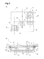
(a) of FIG. 2 is a plan view showing side object detection symbols and (b) of FIG. 2 is an end view taken along line II-II of (a) of FIG. 2.
DESCRIPTION OF THE PREFERRED EMBODIMENTS
A door mirror for an automobile according to a preferred embodiment of the present invention will be described in detail below with reference to the drawings.
Referring to FIG. 1, and (a) and (b) of FIG. 2, the door mirror for an automobile includes a reflective mirror 1 for viewing a rearward vehicle. The reflective mirror 1 is disposed so as to close an opening in a cup-shaped housing. A mechanism for moving the reflective mirror 1 is accommodated inside the housing. The reflective mirror 1 is transparent glass 2 having a back surface on which a reflective film R is vacuum-deposited. The reflective mirror 1 has the back surface covered in a resin mirror holder (not shown) and fitted and fixed in a circumferential edge of the mirror holder.
Side object detection symbols S of an ISO standard are formed on the reflective mirror 1. The side object detection symbols S include a host vehicle display section 10 disposed on the side of a driver's seat, an other vehicle display section 20 disposed outside and obliquely rearwardly of the host vehicle display section 10, and a detected wave display section 30, disposed between the host vehicle display section 10 and the other vehicle display section 20, for indicating a detected wave (for example, a laser wave).
The side object detection symbols S are formed on the back surface of the reflective mirror 1 by peeling the reflective film R from the transparent glass 2 through a blasting process or a laser etching process. The side object detection symbols S formed thereby are constructed of a light transmissive portion A and a light non-transmissive portion B.
In addition, a lamp unit U is affixed and fixed to the back surface of the reflective mirror 1. A first LED 41 and a second LED 42 for illuminating the side object detection symbols S are disposed inside the lamp unit U. Each of the first LED 41 and the second LED 42 is fixed on a circuit board 50. The circuit board 50 is fixed inside a lamp housing 60. The lamp housing 60 has an opening 60 a that is larger than an area M surrounding the side object detection symbols S. Cushion tape 70 has a back surface attached to a circumferential edge of the opening 60 a of the lamp housing 60. The cushion tape 70 has a front surface attached to the back surface of the reflective mirror 1.
The cushion tape 70 has an opening 70 a that is one size larger than the area M. To ensure that the opening 70 a is aligned with the position of the side object detection symbols S, the lamp housing 60 is affixed to the back side of the reflective mirror 1 using the cushion tape 70 with adhesive.
A plate-shaped light diffusing section 80 is fixed to the lamp housing 60 so as to close the opening 60 a in the lamp housing 60. Each of the first LED 41 and the second LED 42 is accommodated inside a space defined by the light diffusing section 80 and the lamp housing 60. Additionally, a circumferential edge of the light diffusing section 80 is retained by an extension portion 60 b formed on the side of the opening 60 a in the lamp housing 60. Employing the light diffusing section 80 allows the first LED 41 and the second LED 42 to be disposed so as to be close to the side object detection symbols S, which enables the lamp housing 60 to be built thinner.
It is noted that the lamp unit U is formed to include the lamp housing 60, the first LED 41, the second LED 42, the circuit board 50, the light diffusing section 80, and the cushion tape 70. Consequently, assembly workability is improved by unitizing a light source.
In addition, as shown in (a) and (b) of FIG. 2, relative dispositions between the side object detection symbols S and the first and second LEDs 41, 42 disposed on the back surface side of the side object detection symbols S are such that the optical axis L1 of the first LED 41 intersects within the host vehicle display section 10 and the optical axis L2 of the second LED 42 intersects within the other vehicle display section 20.
Using three LEDs for uniformly illuminating each of the host vehicle display section 10, the other vehicle display section 20, and the detected wave display section 30 of the side object detection symbols S results in a larger circuit board. If one LED is used so as to illuminate the center of the side object detection symbols S in order to reduce the circuit board in size, a peripheral area of the side object detection symbols S tends to be dark and it is difficult to illuminate the side object detection symbols S uniformly.
Thus, the light diffusing section 80 is disposed between the side object detection symbols S and the first and second LEDs 41, 42, and the relative dispositions between the side object detection symbols S and the first and second LEDs 41, 42 are arranged such that the optical axis L1 of the first LED 41 intersects within the host vehicle display section 10 and the optical axis L2 of the second LED 42 intersects within the other vehicle display section 20. This achieves uniform illumination of the side object detection symbols S using the two first and second LEDs 41, 42.
In addition, the optical axis L1 of the first LED 41 intersects with the light non-transmissive portion B of the host vehicle display section 10 and the optical axis L2 of the second LED 42 intersects with the light non-transmissive portion B of the other vehicle display section 20. Incorporating such an arrangement allows light intensity of the side object detection symbols S as viewed from a following vehicle to be reduced as compared with light intensity of the side object detection symbols S as viewed from the driver's seat of the host vehicle, so that an effect of a steady light or a blinking light of the side object detection symbols S on the driver of the following vehicle can be reduced.
Furthermore, in addition to the optical axes L1, L2 intersecting with the light non-transmissive portion B, the optical axis L1 of the first LED 41 is located closer to the detected wave display section 30 side relative to a central axis P1 that divides the host vehicle display section 10 into right and left sides (right and left sides in a condition in which the door mirror is mounted in the vehicle body) within the host vehicle display section; and the optical axis L2 of the second LED 42 is located closer to the detected wave display section 30 side relative to a central axis P2 that divides the other vehicle display section 20 into right and left sides (right and left sides in a condition in which the door mirror is mounted in the vehicle body) within the other vehicle display section. Incorporating such an arrangement allows brightness of the entire side object detection symbols S to be made even more uniform, while reducing the effect of a steady light or a blinking light of the side object detection symbols S on the driver of the following vehicle.
The side object detection symbols S are formed by subjecting the back surface of the reflective mirror 1 to the blasting process or the laser etching process. Incorporating such an arrangement allows the side object detection symbols S themselves to have a light diffusing effect, so that the side object detection symbols S can be illuminated even more uniformly. The same effect as that achieved by the blasting process can be achieved, in particular, from gas laser etching.
It is to be understood that the present invention is not limited to the embodiment described above. For example, when the side object detection symbols S are to be formed on the back surface of the reflective mirror 1 through the laser etching process, the light diffusing effect can be achieved by roughing the surface of the transparent glass 2 in one case, and in the other, the reflective film R is simply peeled off without the surface of the transparent glass 2 being roughed.

Claims (4)

What is claimed is:
1. A door mirror for an automobile comprising:
a first light-emitting diode (LED); and
a second LED,
the first LED and the second LED illuminating, from a back surface of a reflective mirror, side object detection symbols of an ISO standard,
the side object detection symbols constructed of a light transmissive portion and a light non-transmissive portion and comprising:
a host vehicle display section disposed on a side of a driver's seat;
an other vehicle display section disposed outside and obliquely rearwardly of the host vehicle display section; and
a detected wave display section disposed between the host vehicle display section and the other vehicle display section, for indicating a detected wave, wherein
a light diffusing section is disposed between the side object detection symbols and the first and second LEDs,
relative dispositions between the side object detection symbols and the first and second LEDs disposed on a back surface side of the side object detection symbols are such that an optical axis of the first LED intersects with the host vehicle display section and an optical axis of the second LED intersects with the other vehicle display section.
2. The door mirror for an automobile according to claim 1, wherein the optical axis of the first LED intersects with the light non-transmissive portion of the host vehicle display section and the optical axis of the second LED intersects with the light non-transmissive portion of the other vehicle display section.
3. The door mirror for an automobile according to claim 2, wherein the optical axis of the first LED is located closer to the detected wave display section side relative to a central axis that divides the host vehicle display section into right and left sides within the host vehicle display section, and the optical axis of the second LED is located closer to the detected wave display section side relative to a central axis that divides the other vehicle display section into right and left sides within the other vehicle display section.
4. The door mirror for an automobile according to claim 1, wherein the side object detection symbols are formed by subjecting the back surface of the reflective mirror to a blasting process or a laser etching process.
US13/351,428 2011-03-17 2012-01-17 Door mirror for an automobile Expired - Fee Related US8599037B2 (en)

Applications Claiming Priority (2)

Application Number Priority Date Filing Date Title
JP2011059630A JP5595953B2 (en) 2011-03-17 2011-03-17 Vehicle door mirror
JP2011-059630 2011-03-17

Publications (2)

Publication Number Publication Date
US20120235832A1 US20120235832A1 (en) 2012-09-20
US8599037B2 true US8599037B2 (en) 2013-12-03

Family

ID=46756950

Family Applications (1)

Application Number Title Priority Date Filing Date
US13/351,428 Expired - Fee Related US8599037B2 (en) 2011-03-17 2012-01-17 Door mirror for an automobile

Country Status (4)

Country Link
US (1) US8599037B2 (en)
JP (1) JP5595953B2 (en)
CN (1) CN102673481B (en)
DE (1) DE102012000582A1 (en)

Cited By (2)

* Cited by examiner, † Cited by third party
Publication number Priority date Publication date Assignee Title
KR20160000790U (en) 2014-08-29 2016-03-09 에스엘 주식회사 Side mirror for vehicle
KR20190002472U (en) 2019-09-20 2019-10-02 에스엘 주식회사 Side mirror for vehicle

Families Citing this family (8)

* Cited by examiner, † Cited by third party
Publication number Priority date Publication date Assignee Title
CN202615735U (en) * 2012-04-06 2012-12-19 鸿富锦精密工业(深圳)有限公司 Light-emitting display device
ES2458428B1 (en) * 2012-10-31 2015-02-10 Fico Mirrors, S.A. Vehicle exterior rearview mirror set
CN105313771A (en) * 2015-11-16 2016-02-10 重庆奥科伦实业发展有限公司 Installing method for dead zone reminder lamp assembly
CN105438078A (en) * 2015-11-16 2016-03-30 重庆奥科伦实业发展有限公司 Blind zone warning lamp assembly and fixed structure
CN105313788A (en) * 2015-11-16 2016-02-10 重庆奥科伦实业发展有限公司 Dead zone alarm lamp assembly
JP7393197B2 (en) 2019-12-18 2023-12-06 株式会社村上開明堂 Lamp unit and lamp unit manufacturing method
WO2021235490A1 (en) * 2020-05-19 2021-11-25 株式会社ホンダロック Vehicle door mirror
WO2023139521A1 (en) * 2022-01-19 2023-07-27 Gentex Corporation Rearview mirror assembly having a micro-led illumination subassembly

Citations (12)

* Cited by examiner, † Cited by third party
Publication number Priority date Publication date Assignee Title
US6193380B1 (en) * 1999-04-20 2001-02-27 Raymond A. Jacobs Vehicle blind spot mirror
US6264353B1 (en) * 1998-11-23 2001-07-24 Lear Automotive Dearborn, Inc. Exterior mirror with supplement turn signal
US6572233B1 (en) * 1998-10-14 2003-06-03 Gentex Corporation Rearview mirror with display
US6677856B2 (en) * 2001-11-20 2004-01-13 Richard I. Perlman Wireless remote vehicle signal indicator for supplementing existing vehicle signal indicators
US6927677B2 (en) * 2003-03-14 2005-08-09 Darryll Anderson Blind spot detector system
US7427150B2 (en) * 1999-05-14 2008-09-23 Gentex Corporation Rearview mirror assembly including a multi-functional light module
US7477137B2 (en) * 2005-06-23 2009-01-13 Mazda Motor Corporation Blind-spot detection system for vehicle
US20090063053A1 (en) * 2007-09-04 2009-03-05 International Business Machines Corporation Method and system for blind spot identification and warning utilizing visual indicators
US7517099B2 (en) * 2004-09-10 2009-04-14 Arthur Andre Hannah Automotive blind spot safety system and method
JP2009083631A (en) 2007-09-28 2009-04-23 Murakami Corp Vehicular rear-view mirror
US20120099173A1 (en) * 2010-10-25 2012-04-26 Gentex Corporation Vehicular rearview mirror with increased field-of-view
US20120320444A1 (en) * 2005-05-16 2012-12-20 Donnelly Corporation Rearview mirror element assembly for vehicle

Family Cites Families (12)

* Cited by examiner, † Cited by third party
Publication number Priority date Publication date Assignee Title
JP3861389B2 (en) * 1996-08-21 2006-12-20 松下電工株式会社 lighting equipment
US6356376B1 (en) * 1997-04-02 2002-03-12 Gentex Corporation Electrochromic rearview mirror incorporating a third surface metal reflector and a display/signal light
US6426485B1 (en) * 2001-07-31 2002-07-30 Illinois Tool Works Inc. Light diffusing signal mirror heater
US7241037B2 (en) * 2005-03-23 2007-07-10 K.W. Muth Company Signaling assembly
JP2007011874A (en) * 2005-07-01 2007-01-18 Mazda Motor Corp Rear side alarm system for vehicle
US7379018B1 (en) * 2005-12-30 2008-05-27 Valeo Raytheon Systems, Inc. System and method for verifying a radar detection
EP2378350B1 (en) * 2006-03-09 2013-12-11 Gentex Corporation Vehicle rearview assembly including a high intensity display
JP4791262B2 (en) * 2006-06-14 2011-10-12 本田技研工業株式会社 Driving assistance device
KR20150082671A (en) * 2006-09-29 2015-07-15 오스람 옵토 세미컨덕터스 게엠베하 Organic lighting device and lighting equipment
JP2008116766A (en) * 2006-11-07 2008-05-22 Shimadzu Corp Display unit and virtual image display device
CN201068124Y (en) * 2007-05-09 2008-06-04 陶治中 Vehicular decoration lamp with light conducting coated layer
CN201751872U (en) * 2010-06-24 2011-02-23 广东铁将军防盗设备有限公司 Rearview mirror assembly and the liquid crystal display thereof

Patent Citations (12)

* Cited by examiner, † Cited by third party
Publication number Priority date Publication date Assignee Title
US6572233B1 (en) * 1998-10-14 2003-06-03 Gentex Corporation Rearview mirror with display
US6264353B1 (en) * 1998-11-23 2001-07-24 Lear Automotive Dearborn, Inc. Exterior mirror with supplement turn signal
US6193380B1 (en) * 1999-04-20 2001-02-27 Raymond A. Jacobs Vehicle blind spot mirror
US7427150B2 (en) * 1999-05-14 2008-09-23 Gentex Corporation Rearview mirror assembly including a multi-functional light module
US6677856B2 (en) * 2001-11-20 2004-01-13 Richard I. Perlman Wireless remote vehicle signal indicator for supplementing existing vehicle signal indicators
US6927677B2 (en) * 2003-03-14 2005-08-09 Darryll Anderson Blind spot detector system
US7517099B2 (en) * 2004-09-10 2009-04-14 Arthur Andre Hannah Automotive blind spot safety system and method
US20120320444A1 (en) * 2005-05-16 2012-12-20 Donnelly Corporation Rearview mirror element assembly for vehicle
US7477137B2 (en) * 2005-06-23 2009-01-13 Mazda Motor Corporation Blind-spot detection system for vehicle
US20090063053A1 (en) * 2007-09-04 2009-03-05 International Business Machines Corporation Method and system for blind spot identification and warning utilizing visual indicators
JP2009083631A (en) 2007-09-28 2009-04-23 Murakami Corp Vehicular rear-view mirror
US20120099173A1 (en) * 2010-10-25 2012-04-26 Gentex Corporation Vehicular rearview mirror with increased field-of-view

Non-Patent Citations (1)

* Cited by examiner, † Cited by third party
Title
U.S. Appl. No. 13/351,502 to Shinya Takayanagi, which was filed on Jan. 17, 2012.

Cited By (4)

* Cited by examiner, † Cited by third party
Publication number Priority date Publication date Assignee Title
KR20160000790U (en) 2014-08-29 2016-03-09 에스엘 주식회사 Side mirror for vehicle
US9862308B2 (en) 2014-08-29 2018-01-09 Sl Mirrortech Corporation Vehicle side mirror
USRE49072E1 (en) 2014-08-29 2022-05-17 Sl Mirrortech Corporation Vehicle side mirror
KR20190002472U (en) 2019-09-20 2019-10-02 에스엘 주식회사 Side mirror for vehicle

Also Published As

Publication number Publication date
CN102673481B (en) 2015-06-17
CN102673481A (en) 2012-09-19
JP5595953B2 (en) 2014-09-24
DE102012000582A1 (en) 2012-09-20
JP2012192879A (en) 2012-10-11
US20120235832A1 (en) 2012-09-20

Similar Documents

Publication Publication Date Title
US8599037B2 (en) Door mirror for an automobile
US9434313B2 (en) Low profile optical lighting assembly for use in outside vehicle mirror and method of forming same
US7699511B2 (en) Door mirror with turn lamp
US8169307B2 (en) Vehicle rear-view mirror
US8469563B2 (en) Turn-indicator light module for a vehicle mirror assembly and vehicle mirror assembly comprising a turn-indicator light module
JP4239839B2 (en) Outside mirror device for vehicle
CN106195847B (en) Mood light for vehicle
EP1442930B1 (en) Exterior mirror with light
KR101804311B1 (en) Back light unit
EP3463980B1 (en) A lamp assembly for a vehicle
KR20130106350A (en) Vehicular heads-up display device
US8277062B2 (en) Lamp assembly and housing therefor
JP2019200937A (en) Vehicle lamp fitting
US20120057342A1 (en) Article having back light
WO2020224081A1 (en) Lane change blind area warning lamp
US20120087149A1 (en) Ultra-thin light guide for cluster gauge illumination over display structures
US10896632B1 (en) Lamp assembly
US11453341B2 (en) Vehicle mirror device and illuminatable mirror display device
JP6210425B2 (en) Head-up display device
US20220055533A1 (en) Illuminating device for vehicle ceiling lamp
JP2003237413A (en) Vehicular pointer instrument
JP7356586B2 (en) vehicle door mirror
WO2023157757A1 (en) Lighting tool for vehicle and vehicle rearward illumination system
JP2006194622A (en) Instrument
JP2021174570A (en) Vehicular lighting fixture

Legal Events

Date Code Title Description
AS Assignment

Owner name: MURAKAMI CORPORATION, JAPAN

Free format text: ASSIGNMENT OF ASSIGNORS INTEREST;ASSIGNOR:TAKAYANAGI, SHINYA;REEL/FRAME:027541/0211

Effective date: 20111223

STCF Information on status: patent grant

Free format text: PATENTED CASE

FEPP Fee payment procedure

Free format text: PAYOR NUMBER ASSIGNED (ORIGINAL EVENT CODE: ASPN); ENTITY STATUS OF PATENT OWNER: LARGE ENTITY

FPAY Fee payment

Year of fee payment: 4

FEPP Fee payment procedure

Free format text: MAINTENANCE FEE REMINDER MAILED (ORIGINAL EVENT CODE: REM.); ENTITY STATUS OF PATENT OWNER: LARGE ENTITY

LAPS Lapse for failure to pay maintenance fees

Free format text: PATENT EXPIRED FOR FAILURE TO PAY MAINTENANCE FEES (ORIGINAL EVENT CODE: EXP.); ENTITY STATUS OF PATENT OWNER: LARGE ENTITY

STCH Information on status: patent discontinuation

Free format text: PATENT EXPIRED DUE TO NONPAYMENT OF MAINTENANCE FEES UNDER 37 CFR 1.362

FP Lapsed due to failure to pay maintenance fee

Effective date: 20211203