US8604968B2 - Integrated radar-camera sensor - Google Patents
Integrated radar-camera sensor Download PDFInfo
- Publication number
- US8604968B2 US8604968B2 US13/119,307 US200913119307A US8604968B2 US 8604968 B2 US8604968 B2 US 8604968B2 US 200913119307 A US200913119307 A US 200913119307A US 8604968 B2 US8604968 B2 US 8604968B2
- Authority
- US
- United States
- Prior art keywords
- radar
- sensor module
- vehicle
- sensor
- windshield
- Prior art date
- Legal status (The legal status is an assumption and is not a legal conclusion. Google has not performed a legal analysis and makes no representation as to the accuracy of the status listed.)
- Active, expires
Links
- 238000012545 processing Methods 0.000 claims abstract description 27
- 230000004313 glare Effects 0.000 claims abstract description 22
- 230000010287 polarization Effects 0.000 claims description 32
- 238000000034 method Methods 0.000 claims description 19
- 238000001514 detection method Methods 0.000 claims description 9
- 208000004350 Strabismus Diseases 0.000 claims description 7
- 239000006260 foam Substances 0.000 claims description 6
- 230000008569 process Effects 0.000 claims description 5
- 239000003989 dielectric material Substances 0.000 claims description 2
- 230000005670 electromagnetic radiation Effects 0.000 claims description 2
- 239000011521 glass Substances 0.000 claims description 2
- 230000006870 function Effects 0.000 description 11
- 230000010354 integration Effects 0.000 description 9
- 230000004927 fusion Effects 0.000 description 7
- 230000004438 eyesight Effects 0.000 description 6
- 238000009434 installation Methods 0.000 description 5
- 230000035945 sensitivity Effects 0.000 description 4
- 230000003287 optical effect Effects 0.000 description 3
- 230000009467 reduction Effects 0.000 description 3
- 230000003044 adaptive effect Effects 0.000 description 2
- 230000008901 benefit Effects 0.000 description 2
- 230000000116 mitigating effect Effects 0.000 description 2
- 238000012986 modification Methods 0.000 description 2
- 230000004048 modification Effects 0.000 description 2
- 238000002310 reflectometry Methods 0.000 description 2
- RYGMFSIKBFXOCR-UHFFFAOYSA-N Copper Chemical compound [Cu] RYGMFSIKBFXOCR-UHFFFAOYSA-N 0.000 description 1
- 230000004913 activation Effects 0.000 description 1
- 239000000853 adhesive Substances 0.000 description 1
- 230000001070 adhesive effect Effects 0.000 description 1
- 230000002411 adverse Effects 0.000 description 1
- 238000013459 approach Methods 0.000 description 1
- 230000000295 complement effect Effects 0.000 description 1
- 229910052802 copper Inorganic materials 0.000 description 1
- 239000010949 copper Substances 0.000 description 1
- 238000013461 design Methods 0.000 description 1
- 238000010586 diagram Methods 0.000 description 1
- 230000000694 effects Effects 0.000 description 1
- 238000003384 imaging method Methods 0.000 description 1
- 238000010348 incorporation Methods 0.000 description 1
- 238000004519 manufacturing process Methods 0.000 description 1
- 239000000463 material Substances 0.000 description 1
- 239000007769 metal material Substances 0.000 description 1
- 238000005457 optimization Methods 0.000 description 1
- 238000004806 packaging method and process Methods 0.000 description 1
- 230000008439 repair process Effects 0.000 description 1
- 230000001360 synchronised effect Effects 0.000 description 1
- 239000013598 vector Substances 0.000 description 1
Images


Classifications
-
- B—PERFORMING OPERATIONS; TRANSPORTING
- B60—VEHICLES IN GENERAL
- B60R—VEHICLES, VEHICLE FITTINGS, OR VEHICLE PARTS, NOT OTHERWISE PROVIDED FOR
- B60R11/00—Arrangements for holding or mounting articles, not otherwise provided for
- B60R11/04—Mounting of cameras operative during drive; Arrangement of controls thereof relative to the vehicle
-
- B—PERFORMING OPERATIONS; TRANSPORTING
- B60—VEHICLES IN GENERAL
- B60R—VEHICLES, VEHICLE FITTINGS, OR VEHICLE PARTS, NOT OTHERWISE PROVIDED FOR
- B60R11/00—Arrangements for holding or mounting articles, not otherwise provided for
- B60R11/02—Arrangements for holding or mounting articles, not otherwise provided for for radio sets, television sets, telephones, or the like; Arrangement of controls thereof
-
- G—PHYSICS
- G01—MEASURING; TESTING
- G01S—RADIO DIRECTION-FINDING; RADIO NAVIGATION; DETERMINING DISTANCE OR VELOCITY BY USE OF RADIO WAVES; LOCATING OR PRESENCE-DETECTING BY USE OF THE REFLECTION OR RERADIATION OF RADIO WAVES; ANALOGOUS ARRANGEMENTS USING OTHER WAVES
- G01S13/00—Systems using the reflection or reradiation of radio waves, e.g. radar systems; Analogous systems using reflection or reradiation of waves whose nature or wavelength is irrelevant or unspecified
- G01S13/86—Combinations of radar systems with non-radar systems, e.g. sonar, direction finder
- G01S13/867—Combination of radar systems with cameras
-
- G—PHYSICS
- G01—MEASURING; TESTING
- G01S—RADIO DIRECTION-FINDING; RADIO NAVIGATION; DETERMINING DISTANCE OR VELOCITY BY USE OF RADIO WAVES; LOCATING OR PRESENCE-DETECTING BY USE OF THE REFLECTION OR RERADIATION OF RADIO WAVES; ANALOGOUS ARRANGEMENTS USING OTHER WAVES
- G01S13/00—Systems using the reflection or reradiation of radio waves, e.g. radar systems; Analogous systems using reflection or reradiation of waves whose nature or wavelength is irrelevant or unspecified
- G01S13/88—Radar or analogous systems specially adapted for specific applications
- G01S13/93—Radar or analogous systems specially adapted for specific applications for anti-collision purposes
- G01S13/931—Radar or analogous systems specially adapted for specific applications for anti-collision purposes of land vehicles
-
- B—PERFORMING OPERATIONS; TRANSPORTING
- B60—VEHICLES IN GENERAL
- B60R—VEHICLES, VEHICLE FITTINGS, OR VEHICLE PARTS, NOT OTHERWISE PROVIDED FOR
- B60R11/00—Arrangements for holding or mounting articles, not otherwise provided for
- B60R2011/0001—Arrangements for holding or mounting articles, not otherwise provided for characterised by position
- B60R2011/0003—Arrangements for holding or mounting articles, not otherwise provided for characterised by position inside the vehicle
- B60R2011/0026—Windows, e.g. windscreen
-
- B—PERFORMING OPERATIONS; TRANSPORTING
- B60—VEHICLES IN GENERAL
- B60R—VEHICLES, VEHICLE FITTINGS, OR VEHICLE PARTS, NOT OTHERWISE PROVIDED FOR
- B60R11/00—Arrangements for holding or mounting articles, not otherwise provided for
- B60R2011/0042—Arrangements for holding or mounting articles, not otherwise provided for characterised by mounting means
- B60R2011/0049—Arrangements for holding or mounting articles, not otherwise provided for characterised by mounting means for non integrated articles
- B60R2011/0064—Connection with the article
- B60R2011/0075—Connection with the article using a containment or docking space
-
- B—PERFORMING OPERATIONS; TRANSPORTING
- B60—VEHICLES IN GENERAL
- B60R—VEHICLES, VEHICLE FITTINGS, OR VEHICLE PARTS, NOT OTHERWISE PROVIDED FOR
- B60R2300/00—Details of viewing arrangements using cameras and displays, specially adapted for use in a vehicle
- B60R2300/10—Details of viewing arrangements using cameras and displays, specially adapted for use in a vehicle characterised by the type of camera system used
- B60R2300/108—Details of viewing arrangements using cameras and displays, specially adapted for use in a vehicle characterised by the type of camera system used using 'non-standard' camera systems, e.g. camera sensor used for additional purposes i.a. rain sensor, camera sensor split in multiple image areas
-
- B—PERFORMING OPERATIONS; TRANSPORTING
- B60—VEHICLES IN GENERAL
- B60R—VEHICLES, VEHICLE FITTINGS, OR VEHICLE PARTS, NOT OTHERWISE PROVIDED FOR
- B60R2300/00—Details of viewing arrangements using cameras and displays, specially adapted for use in a vehicle
- B60R2300/30—Details of viewing arrangements using cameras and displays, specially adapted for use in a vehicle characterised by the type of image processing
- B60R2300/301—Details of viewing arrangements using cameras and displays, specially adapted for use in a vehicle characterised by the type of image processing combining image information with other obstacle sensor information, e.g. using RADAR/LIDAR/SONAR sensors for estimating risk of collision
-
- B—PERFORMING OPERATIONS; TRANSPORTING
- B60—VEHICLES IN GENERAL
- B60R—VEHICLES, VEHICLE FITTINGS, OR VEHICLE PARTS, NOT OTHERWISE PROVIDED FOR
- B60R2300/00—Details of viewing arrangements using cameras and displays, specially adapted for use in a vehicle
- B60R2300/80—Details of viewing arrangements using cameras and displays, specially adapted for use in a vehicle characterised by the intended use of the viewing arrangement
- B60R2300/804—Details of viewing arrangements using cameras and displays, specially adapted for use in a vehicle characterised by the intended use of the viewing arrangement for lane monitoring
-
- B—PERFORMING OPERATIONS; TRANSPORTING
- B60—VEHICLES IN GENERAL
- B60R—VEHICLES, VEHICLE FITTINGS, OR VEHICLE PARTS, NOT OTHERWISE PROVIDED FOR
- B60R2300/00—Details of viewing arrangements using cameras and displays, specially adapted for use in a vehicle
- B60R2300/80—Details of viewing arrangements using cameras and displays, specially adapted for use in a vehicle characterised by the intended use of the viewing arrangement
- B60R2300/8093—Details of viewing arrangements using cameras and displays, specially adapted for use in a vehicle characterised by the intended use of the viewing arrangement for obstacle warning
-
- G—PHYSICS
- G01—MEASURING; TESTING
- G01S—RADIO DIRECTION-FINDING; RADIO NAVIGATION; DETERMINING DISTANCE OR VELOCITY BY USE OF RADIO WAVES; LOCATING OR PRESENCE-DETECTING BY USE OF THE REFLECTION OR RERADIATION OF RADIO WAVES; ANALOGOUS ARRANGEMENTS USING OTHER WAVES
- G01S13/00—Systems using the reflection or reradiation of radio waves, e.g. radar systems; Analogous systems using reflection or reradiation of waves whose nature or wavelength is irrelevant or unspecified
- G01S13/88—Radar or analogous systems specially adapted for specific applications
- G01S13/93—Radar or analogous systems specially adapted for specific applications for anti-collision purposes
- G01S13/931—Radar or analogous systems specially adapted for specific applications for anti-collision purposes of land vehicles
- G01S2013/93185—Controlling the brakes
-
- G—PHYSICS
- G01—MEASURING; TESTING
- G01S—RADIO DIRECTION-FINDING; RADIO NAVIGATION; DETERMINING DISTANCE OR VELOCITY BY USE OF RADIO WAVES; LOCATING OR PRESENCE-DETECTING BY USE OF THE REFLECTION OR RERADIATION OF RADIO WAVES; ANALOGOUS ARRANGEMENTS USING OTHER WAVES
- G01S13/00—Systems using the reflection or reradiation of radio waves, e.g. radar systems; Analogous systems using reflection or reradiation of waves whose nature or wavelength is irrelevant or unspecified
- G01S13/88—Radar or analogous systems specially adapted for specific applications
- G01S13/93—Radar or analogous systems specially adapted for specific applications for anti-collision purposes
- G01S13/931—Radar or analogous systems specially adapted for specific applications for anti-collision purposes of land vehicles
- G01S2013/9321—Velocity regulation, e.g. cruise control
-
- G—PHYSICS
- G01—MEASURING; TESTING
- G01S—RADIO DIRECTION-FINDING; RADIO NAVIGATION; DETERMINING DISTANCE OR VELOCITY BY USE OF RADIO WAVES; LOCATING OR PRESENCE-DETECTING BY USE OF THE REFLECTION OR RERADIATION OF RADIO WAVES; ANALOGOUS ARRANGEMENTS USING OTHER WAVES
- G01S13/00—Systems using the reflection or reradiation of radio waves, e.g. radar systems; Analogous systems using reflection or reradiation of waves whose nature or wavelength is irrelevant or unspecified
- G01S13/88—Radar or analogous systems specially adapted for specific applications
- G01S13/93—Radar or analogous systems specially adapted for specific applications for anti-collision purposes
- G01S13/931—Radar or analogous systems specially adapted for specific applications for anti-collision purposes of land vehicles
- G01S2013/9327—Sensor installation details
- G01S2013/93276—Sensor installation details in the windshield area
-
- H—ELECTRICITY
- H01—ELECTRIC ELEMENTS
- H01Q—ANTENNAS, i.e. RADIO AERIALS
- H01Q1/00—Details of, or arrangements associated with, antennas
- H01Q1/27—Adaptation for use in or on movable bodies
- H01Q1/32—Adaptation for use in or on road or rail vehicles
- H01Q1/3208—Adaptation for use in or on road or rail vehicles characterised by the application wherein the antenna is used
- H01Q1/3233—Adaptation for use in or on road or rail vehicles characterised by the application wherein the antenna is used particular used as part of a sensor or in a security system, e.g. for automotive radar, navigation systems
-
- H—ELECTRICITY
- H01—ELECTRIC ELEMENTS
- H01Q—ANTENNAS, i.e. RADIO AERIALS
- H01Q1/00—Details of, or arrangements associated with, antennas
- H01Q1/27—Adaptation for use in or on movable bodies
- H01Q1/32—Adaptation for use in or on road or rail vehicles
- H01Q1/325—Adaptation for use in or on road or rail vehicles characterised by the location of the antenna on the vehicle
-
- H—ELECTRICITY
- H01—ELECTRIC ELEMENTS
- H01Q—ANTENNAS, i.e. RADIO AERIALS
- H01Q1/00—Details of, or arrangements associated with, antennas
- H01Q1/52—Means for reducing coupling between antennas; Means for reducing coupling between an antenna and another structure
- H01Q1/526—Electromagnetic shields
Definitions
- the present invention generally relates to an integrated radar and camera module (RACam) for detecting the presence of an object, and more specifically relates to such a sensor module that detects objects, such as objects near a vehicle, for enhanced vehicle safety.
- RACam integrated radar and camera module
- Radar and camera sensors are often employed on vehicles to enable systems for enhanced vehicle safety including Adaptive Cruise Control (ACC), Forward Collision Warning (FCW), collision mitigation or avoidance via autonomous braking, pre-crash functions such as airbag arming or pre-activation, and Lane Departure Warning (LDW).
- ACC Adaptive Cruise Control
- FCW Forward Collision Warning
- LWD Lane Departure Warning
- Systems that employ both radar and camera sensors provide high level active safety capability and are available on production vehicles.
- the cost of conventional systems is typically high and integration into the vehicle system is generally complex, due to the need for multiple sensors at multiple locations, currently limiting these systems to optional equipment on luxury vehicles.
- a sensor module comprising a sensor module housing comprising a plurality of walls.
- a camera is located in the module housing for capturing images based on light waves.
- a radar sensor component is also located within the module housing for emitting a radar beam and receiving reflected radar signals.
- the sensor module further includes processing circuitry for processing the captured images and the received reflected radar signals and providing an indication of the detection of a presence of one or more objects.
- a sensor module for use on a vehicle for detecting one or more objects relative to the vehicle.
- the sensor module comprises a sensor module housing behind a windshield of a vehicle, and a radar sensor component located within the housing behind the windshield.
- An electromagnetic interference shield is disposed to one or more sides of the radar sensor for shielding electromagnetic radiation from the radar sensor component.
- the sensor module further includes processing circuitry for processing radar signals received with the radar sensor component.
- a method for detecting one or more objects relative to a vehicle comprises the steps of providing a camera component in a module housing and providing a radar sensor component in the module housing to provide an integrated sensor module, and mounting the sensor module behind a windshield of the vehicle.
- the method also includes the steps of capturing images forward of the vehicle passing through the windshield with the camera component, transmitting a radar signal forward of the vehicle through the windshield with the radar sensor component, and receiving reflected radar signals from one or more objects forward of the vehicle with the radar sensor component.
- the method further includes the step of processing the video images captured by the camera component and the reflected radar signals received by the radar sensor component for use in detecting an object relative to the vehicle.
- FIG. 1 is a top view of a vehicle employing an integrated radar-camera sensor behind the windshield, according to one embodiment
- FIG. 2 is a block diagram illustrating the integrated radar-camera sensor, according to one embodiment
- FIG. 3 is a perspective view of the integrated radar-camera sensor arranged forward of a rearview mirror assembly, according to one embodiment
- FIG. 4 is a side view of the integrated radar-camera sensor shown mounted to the interior surface of the windshield of the vehicle;
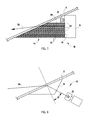
- FIG. 5 is a perspective view of an integrated radar-camera sensor employing a tilted radar antenna, according to another embodiment
- FIG. 6 is a side view of the integrated radar-camera sensor employing the tilted radar antenna in FIG. 5 ;
- FIG. 7 is a side cross-sectional view of an integrated radar-camera sensor employing an electromagnetic interference (EMI) shield, according to another embodiment
- FIG. 8 is a side view of an integrated radar-camera sensor employing a refractive block, according to a further embodiment
- FIG. 9 is a graph illustrating reflection loss versus incidence angle for parallel (vertical) polarization provided by a radar antenna
- FIG. 10 is a graph illustrating reflection loss versus incidence angle for a perpendicular (horizontal) polarization provided by a radar antenna
- FIG. 11 is a graph illustrating sensitivities near and beyond the Brewster angle at 76.5 gigahertz (GHz) vertical polarization
- FIG. 12 is a graph illustrating sensitivities near and beyond the Brewster angle at 76.5 gigahertz vertical polarization.
- FIG. 13 is a graph illustrating potential additional loss and the impact of the azimuth angle.
- an automotive vehicle 10 is generally illustrated employing an integrated radar-camera sensor module 20 generally shown located in the vehicle interior compartment behind the windshield 12 and generally forward of the interior rearview mirror 14 .
- the integrated radar-camera sensor module 20 includes a radar sensor component for transmitting radar signals through the windshield 12 and forward of the vehicle 10 in a radar field of view horizontal coverage zone shown by dashed lines 150 and receives reflected radar signals that are reflected off of one or more objects within the coverage zone 150 .
- the integrated radar-camera sensor module 20 employs a camera component for capturing images based on light waves that are seen and captured through the windshield 12 in a camera field of view horizontal coverage zone shown by dashed line 160 .
- the automotive vehicle 10 may include a passenger car having road wheels for engaging a road, according to one embodiment.
- the integrated radar-camera sensor module 20 detects one or more objects relative to the vehicle 10 . Additionally, the sensor module 20 may have further capabilities to estimate the parameters of the detected object(s) including, for example, the object position and velocity vectors, target size, and classification, e.g., vehicle verses pedestrian.
- the integrated radar-camera sensor module 20 may be employed onboard the vehicle 10 for automotive safety applications including adaptive cruise control (ACC), forward collision warning (FCW), and collision mitigation or avoidance via autonomous braking and lane departure warning (LDW).
- ACC adaptive cruise control
- FCW forward collision warning
- LWD autonomous braking and lane departure warning
- the integrated radar-camera sensor module 20 advantageously integrates both radar and camera in a single module contained within a common housing.
- the integrated radar-camera sensor module 20 is advantageously installed within the passenger compartment of the vehicle 10 , behind the windshield 12 and in front of the rearview mirror assembly 14 .
- the integration of the camera and the radar into a common single module advantageously results in a reduction in sensor costs.
- the camera and radar integration advantageously employs common or shared electronics and signal processing as shown in FIG. 2 .
- the integrated signal processor architecture employed by the sensor module 20 enables low level radar-camera data fusion.
- the radar may employ a radar antenna with vertical polarization for effective operation behind the windshield 12 .
- the radar antenna and camera may be integrated onto a single board.
- the camera may employ a wafer scale camera, according to one embodiment.
- a glare shield may be employed to shield glare from the camera, or alternatively refractive block optics may be employed to eliminate the need for the glare shield.
- a parallel plate lens for the radar antenna may be employed to minimize size of an electromagnetic interference shield and to squint the radar beam output.
- a joint radar-camera alignment technique may be employed to advantageously align both the radar and the camera provided in the integrated radar-camera sensor module. Further, optimized radar-camera fusion may exploit the complimentary sensor attributes to minimize radar component specification and costs.
- the sensing module 20 advantageously employs a sensor module housing 100 comprising a plurality of walls as shown in FIGS. 3 and 4 , according to one embodiment.
- the sensor module 20 includes a camera component 22 located in the module housing 100 for capturing images based on light waves.
- Sensor module 20 also includes a radar sensor component 30 located within the module housing 100 for emitting a radar beam and receiving reflected radar signals.
- the sensing module 20 further includes processing circuitry 50 for processing the captured images and the received reflected radar signals and providing an indication of the detection of the presence of one or more objects detected in the coverage zones 150 and 160 .
- the integrated radar-camera sensor module 20 is shown in FIG. 2 having various components, according to one embodiment.
- the sensor module 20 includes the radar component 30 , the camera component 22 , the radar-camera processing unit 50 and an application control unit 72 .
- the radar component 30 and camera component 22 both communicate with the radar-camera processing unit 50 to process the received radar signals and camera generated images so that the sensed radar and camera signals are useful for various radar and vision functions.
- the application control unit 72 may be integrated within the radar-camera processing unit or may be separate therefrom.
- the application control unit 72 may execute any of a number of known applications that utilize the processed radar and camera signals including, but not limited to ACC, FCW and LDW.
- the camera component 22 is shown in FIG. 2 including both optics 24 and imager 26 . It should be appreciated that the camera component 22 may include a commercially available off the shelf camera for generating video images. For example, the camera component 22 may include a wafer scale camera, or other image acquisition device. Camera component 22 receives power from the power supply 58 of processing unit 50 and communicates data and control signals with a video microcontroller 52 of the radar-camera processing unit 50 .
- the radar component 30 is shown having a radar transceiver 32 coupled to an antenna 48 .
- the transceiver 32 and antenna 48 operate to transmit radar signals within the desired coverage zone or beam 150 and to receive reflected radar signals reflected from objects within the coverage zone 150 .
- the radar component 30 may transmit a single fan-shaped radar beam and form multiple receive beams by receive digital beamforming, according to one embodiment.
- the antenna 48 may include a vertical polarization antenna for providing vertical polarization of the radar signal which provides good propagation over angles of interest for the windshield, such as a seventy degree (70°) incidence angle. Alternately, a horizontal polarization antenna may be employed; however, the horizontal polarization is more sensitive to the RF properties and parameters of the windshield for high incidence angle.
- the radar component 30 may also include a switch driver 34 coupled to the transceiver 32 and further coupled to a programmable logic device (PLD) 36 .
- the programmable logic device (PLD) 36 controls the switch driver in a manner synchronous with the analog-to-digital converter (ADC) 38 which, in turn, samples and digitizes signals received from the transceiver 32 .
- the radar component 30 also includes a waveform generator 40 and a linearizer 42 .
- the radar sensor 30 may generate a fan-shaped output which may be achieved using electronic beam forming techniques.
- One example of a suitable radar sensor operates at a frequency of 76.5 gigahertz. It should be appreciated that the automotive radar may operate in one of several other available frequency bands, including 24 GHz ISM, 24 GHz UWB, 76.5 GHz, and 79 GHz.
- the radar-camera processing unit 50 is shown employing a video microcontroller 52 , which includes processing circuitry, such as a microprocessor.
- the video microcontroller 52 communicates with memory 54 which may include SDRAM and flash memory, amongst other available memory devices.
- a debugging USB2 device 56 is also shown communicating with the video microcontroller 52 .
- the video microcontroller 52 communicates data and control with each of the radar component 30 and camera component 22 . This may include the video microcontroller 52 controlling the radar component 30 and camera component 22 and includes receiving images from the camera component 22 and digitized samples of the received reflected radar signals from the radar component 30 .
- the video microcontroller 52 may process the received radar signals and camera images and provide various radar and vision functions.
- the radar functions executed by video microcontroller 52 may include radar detection 60 , tracking 62 and threat assessment 64 , each of which may be implemented via a routine or algorithm.
- the video microcontroller 52 may implement vision functions including lane tracking 66 , vehicle detection 68 , and pedestrian detection 70 , each of which may be implanted via routines or algorithms. It should be appreciated that the video microcontroller 52 may perform various functions related to either radar or vision utilizing one or both of the outputs of the radar component 30 and camera component 22 .
- the application control unit 72 is shown communicating with the video microcontroller 52 by way of a controller area network (CAN) bus and a vision output line.
- the application control unit 72 includes an application microcontroller 74 coupled to memory 76 which may include electronically erasable programmable read-only memory (EEPROM), amongst other memory devices.
- the application control unit 72 is also shown including an RTC watchdog 78 , temperature monitor 80 and input/output interface for diagnostics 82 , and CAN/HW interface 84 .
- the application control unit 72 includes a twelve (12) volt power supply 86 which may be a connection to the vehicle battery.
- the application control unit 72 includes a private CAN interface 88 and a vehicle CAN interface 90 , both shown connected to an electronic control unit (ECU) that is connected to connector 92 .
- the application control unit 72 may be implemented as a separate unit integrated within the sensor module 20 or may be located remote from the sensor module 20 and may be implemented with other vehicle control functions, such as a vehicle engine control unit. It should further be appreciated that functions performed by the application control unit 72 may be performed by the video microcontroller 52 , without departing from the teachings of the present invention.
- the camera component 20 generally captures camera images of an area in front of the vehicle 10 .
- the radar component 30 may emit a fan-shaped radar beam so that objects generally in front of the vehicle reflect the emitted radar back to the sensor.
- the radar-camera processing unit 50 processes the radar and vision data collected by the corresponding camera component 22 and radar component 30 and may process the information in a number of ways.
- One example of processing of radar and camera information is disclosed in U.S. Patent Application Publication No. 2007/0055446, which is assigned to the assignee of the present application, the disclosure of which is hereby incorporated herein by reference.
- the sensor module 20 is generally illustrated having a housing 100 containing the various components thereof.
- the housing 100 may include a polymeric or metallic material having a plurality of walls that generally contain and enclose the components therein.
- Housing 100 has an angled top surface 102 shaped to conform to the interior shape of the vehicle windshield 12 .
- Angled surface 102 may be connected to windshield 12 via an adhesive, according to one embodiment.
- housing 100 may otherwise be attached to windshield 12 or to another location behind the windshield 12 within the passenger compartment of the vehicle 10 .
- the sensor module 20 has the camera component 22 generally shown mounted near an upper end and the radar component 30 is mounted generally therebelow. However, the camera component 22 and radar component 30 may be located at other locations relative to each other.
- the radar component 30 includes a vertical oriented antenna 48 mounted generally at the forward side of the radar component 30 for providing a vertical polarized signal.
- the radar antenna 48 may be a planar antenna such as a patch antenna.
- a glare shield 28 is further provided shown as a lower wall of the housing 100 generally below the camera 22 .
- the glare shield 28 generally shields light reflection or glare from adversely affecting the light images received by the camera 22 . This includes preventing glare from reflecting off of the vehicle dash or other components within the vehicle and into the imaging view of the camera 22 .
- an electromagnetic interference (EMI) shield may be located in front or below the radar sensor component 30 .
- the EMI shield may generally be configured to constrain the radar signals to a generally forward direction passing through the windshield 12 , and to prevent or minimize radar signals that may otherwise pass into the vehicle 10 .
- the camera component 22 and radar sensor component 30 may be mounted onto a common circuit board which, in turn, communicates with the control circuitry 50 , all housed together within the housing 100 .
- an integrated radar-camera sensor module 20 is generally illustrated having a tilted antenna 48 oriented in a plane at any angle relative to the vertical axis, according to another embodiment.
- the radar antenna 48 is tilted at an angle ⁇ relative to the vertical orientation of the embodiment shown in FIG. 4 .
- the radar antenna may be tilted at angle ⁇ in the range of about ten degrees (10°) to seventy degrees (70°) relative to the vertical orientation.
- the radar antenna 48 is tilted at the same angle ⁇ generally as the angle of the windshield 12 .
- the radar beam is squinted downward to illuminate the required coverage zone. Squinting of the radar signal may be achieved by an antenna feed network providing a designed phase slope.
- an integrated radar-camera sensor module 20 is illustrated according to a third embodiment employing a parallel plate lens structure 44 generally positioned forward of the radar sensor 30 .
- the parallel plate lens also functions as an EMI shield.
- the parallel plate lens 44 includes a plurality of substantially horizontal conductive plates or sheets 122 extending from the vertical oriented antenna 48 of the radar component 30 to the interior surface of the vehicle windshield 12 .
- the conductive parallel plates 122 may comprise parallel copper sheets which are dielectrically isolated from each other and are separated therefrom by a distance such as one half the operating wavelength of the radar in the lens, where the operating wavelength in the lens depends on the free space wavelength of the radar and the properties of the material, if any, used between the parallel plates.
- the parallel plate lens 44 further includes a dielectric foam 120 disposed between adjacent layers of the conductive sheets 122 .
- the dielectric foam is electrically nonconductive and supports the horizontal layering of the conductive sheets 122 .
- the dielectric foam 120 has a dielectric constant that provides beam squint in the downward direction such that the radar beam 150 is redirected at an adjusted angle toward the roadway in front of the vehicle 10 as it passes through the windshield 12 .
- the conductive sheets 122 and dielectric foam 120 may operate as a lens which extends the antenna aperture up to the windshield 12 and squints down the radar beam while operating as an electromagnetic interference shield.
- the EMI shield may encompass the fan out of the radar beam beginning from the antenna out to the projection of the beam on the windshield.
- the parallel plate lens serves to reduce the size of the EMI shield since, when using the lens, the radar beam does not fan out until it reaches the windshield 12 . Without incorporating the lens into the EMI shield, the radar beam projection on the windshield is much larger necessitating a much larger EMI shield.
- a refractive block 96 is shown adhered to the front interior surface of the windshield 12 in front of the camera 22 such that the refractive block 96 is in the optical line of sight of camera 22 .
- the refractive block 96 may include a light-entrance surface configured to be mounted in contact with a refractive boundary of the vehicle, namely, the windshield 12 , and a light exit surface wherein the refractive block 96 is configured to refract an optical path of light corresponding to an imaged area and to direct the light to an image sensing component, namely, the camera 22 .
- Light enters the refractive block 96 and enters into an air gap before entering the lens of the camera 22 as shown.
- the air gap may be eliminated with proper lens optimization.
- the bottom and sides of the refractive block 96 may further be roughened to reduce reflectivity and may be painted an opaque color, such as black.
- One example of the refractive block 96 is disclosed in U.S. Pat. No. 7,095,567, assigned to the assignee of the present application, the entire disclosure of which is hereby incorporated herein by reference.
- the refractive block 96 is shown having an incidence angle ⁇ of approximately seventy degrees (70°), according to one example.
- the incidence angle ⁇ generally is the angle between the camera 22 and the windshield 12 and a line perpendicular to the windshield 12 .
- the opaque surface on the bottom side of the refractive block 96 and also on the sides thereof may advantageously prevent reflectivity of light or glare to the camera component 22 thereby providing the function of a glare shield but with smaller overall dimensions than a conventional glare shield.
- the refractive block 96 may further operate to shield the radar sensor component 30 from electromagnetic interference.
- the radar antenna 48 is designed with vertical polarization to mitigate RF propagation issues which may be introduced by the windshield 12 .
- the typical vehicle windshield reflection loss may vary depending upon thickness and incidence angle of the windshield 12 .
- the one-way reflection loss in decibels (dB) at a radar frequency of 76.5 GHz and using parallel (vertical) polarization achieved with the vertical polarization antenna 48 is illustrated in FIG. 9 for a windshield having various thicknesses and as a function of incidence angle of the windshield in degrees.
- the vertical polarization provides good propagation near seventy degree (70°) incidence angle with low sensitivity to incidence angle and windshield thickness.
- a perpendicular (horizontal) polarization antenna is much more sensitive to incidence angle and windshield thickness and typically generates greater reflection loss in a windshield as shown in FIG. 10 . Accordingly, the parallel vertical polarization antenna provides better propagation for typical windshield parameters.
- the sensitivities near and beyond the Brewster angle at a frequency of 76.5 GHz for vertical polarization is illustrated in FIGS. 11 and 12 .
- the graphs shown in FIGS. 11 and 12 generally illustrate the reflection loss versus incidence angle versus windshield thickness in FIG. 11 and versus windshield dielectric constant (dk) in FIG. 12 .
- the reflection loss is relatively insensitive to thickness for an incidence angle of less than seventy-eight degrees (78°), and the reflection loss is relatively insensitive to dk for nominal dk of 7.0 (the typical dk for windshield glass).
- the impact of the azimuth angle is generally illustrated in terms of potential additional loss due to reflection loss of windshield based on the azimuth angle.
- the two-way reflection loss versus azimuth angle shows that an azimuth angle of ⁇ twenty-two and one half degrees (22.5°) for a total coverage zone angle of forty-five degrees (45°) provides for acceptable minimal additional losses.
- the sensor module 20 is designed with common (shared) electronics and signal processor subsystems for the radar and camera front-ends. Further, the camera optics and imager are integrated into the radar antenna board (a wafer scale camera can be incorporated if needed for integration into the antenna board).
- the shared signal processor architecture enables fusion of low-level radar and camera data that, in the case of separate radar and camera modules, would otherwise require a high bandwidth interface with attendant increase in cost. Low-level data fusion provides the opportunity for improvements in object size estimation (e.g., length and width), object classification, road geometry estimation, etc.
- the glare shield 28 may require the glare shield 28 for optimal performance of the camera 22 .
- the EMI shield 44 may be required or expected to allow optimal use of the radar 30 .
- the shield structures may extend out to meet the windshield 12 .
- a glare shield or EMI shield may fan-out in size from the camera and/or radar antenna in order to not obscure their field of view and may lead to a larger package size due to the rake angle of the windshield. Incorporation of the EMI shield may obviate the need for a separate camera glare shield. Otherwise, use of refractive block optics is included to eliminate the camera glare shield.
- a lens structure for parallel plate propagation may be used to effectively translate the antenna 48 to the windshield 12 without fan-out of the radar beam. Further, the lens structure may be designed with a dielectric material to squint the beam as needed to obtain the required elevation pointing and coverage.
- Another option to minimize the size of (or perhaps eliminate the need for) the glare shield or EMI shield is to incorporate the radar antenna 48 with tilt-back to orient the antenna parallel (or nearly parallel) to the windshield 12 .
- the distance between the windshield 12 and the antenna 48 and camera 22 is thereby minimized and the growth in module package size to extend any outer shield to the windshield 12 is also minimized
- the radar antenna 48 is then designed with substantial squint in elevation to obtain the required elevation pointing and coverage.
- Alignment of the radar and camera components 22 and 30 to each other and to the vehicle 10 is typically required for proper system performance.
- the sensor module 20 is designed to support a “net-build” approach, that is, adequate margin in sensor coverage is implemented to eliminate the need for adjustable mechanical alignment features.
- the joint radar-camera alignment concept incorporates camera-based electronic alignment in the vehicle assembly plant for initial alignment of the system. Then, during on-road operation, camera-based automatic electronic alignment is used to maintain alignment to the vehicle and sensor fusion is used to electronically align the radar 30 to the camera 22 .
- Cost reduction is achieved due to integration of the radar and camera components 22 and 30 in a single module 20 using common (shared) subsystems and integrated packaging as described above. Further, installation costs are reduced in two ways; the need to install only a single module and installation of the module 20 behind the windshield 12 .
- current systems typically employ separate radar and camera modules, with the camera typically installed behind the windshield 12 and the radar typically installed in the front grille area or behind the front bumper. Radar installation in this area often leads to costly mounting brackets and/or costly modifications to the vehicle grille or bumper. Further, the radar component is susceptible to damage in a frontal impact leading to potentially higher repair cost compared to installation behind the windshield.
- the integrated radar-camera sensor 20 advantageously integrates the radar and camera into a single housing module which employs integrated control and signal processing circuitry to achieve an advanced integrated sensor for use in a vehicle 10 .
- the sensor module 20 may be easily installed behind the windshield 12 of the vehicle 10 and may be effectively utilized to detect objects to one side of the vehicle 10 , such as in front of the vehicle 10 , and to measure the parameters of detected objects.
- the resulting integrated radar-camera sensor module 20 advantageously provides for an effective system that is cost affordable and provides advanced object detection capabilities.
Abstract
Description
Claims (31)
Priority Applications (1)
| Application Number | Priority Date | Filing Date | Title |
|---|---|---|---|
| US13/119,307 US8604968B2 (en) | 2008-10-08 | 2009-10-06 | Integrated radar-camera sensor |
Applications Claiming Priority (3)
| Application Number | Priority Date | Filing Date | Title |
|---|---|---|---|
| US10368008P | 2008-10-08 | 2008-10-08 | |
| US13/119,307 US8604968B2 (en) | 2008-10-08 | 2009-10-06 | Integrated radar-camera sensor |
| PCT/US2009/059650 WO2010042483A1 (en) | 2008-10-08 | 2009-10-06 | Integrated radar-camera sensor |
Publications (2)
| Publication Number | Publication Date |
|---|---|
| US20110163904A1 US20110163904A1 (en) | 2011-07-07 |
| US8604968B2 true US8604968B2 (en) | 2013-12-10 |
Family
ID=42100916
Family Applications (1)
| Application Number | Title | Priority Date | Filing Date |
|---|---|---|---|
| US13/119,307 Active 2030-06-08 US8604968B2 (en) | 2008-10-08 | 2009-10-06 | Integrated radar-camera sensor |
Country Status (4)
| Country | Link |
|---|---|
| US (1) | US8604968B2 (en) |
| EP (1) | EP2340185B1 (en) |
| JP (2) | JP2012505115A (en) |
| WO (1) | WO2010042483A1 (en) |
Cited By (45)
| Publication number | Priority date | Publication date | Assignee | Title |
|---|---|---|---|---|
| US20140159942A1 (en) * | 2012-09-14 | 2014-06-12 | Delphi Technologies, Inc. | Partial covering radome for a radar unit |
| US20150177374A1 (en) * | 2013-12-23 | 2015-06-25 | Elwha Llc | Systems and methods for concealed radar imaging |
| US20160093944A1 (en) * | 2014-09-30 | 2016-03-31 | Nidec Elesys Corporation | On-vehicle radar device and vehicle |
| US20160300106A1 (en) * | 2015-04-09 | 2016-10-13 | Bendix Commercial Vehicle Systems Llc | Method and Apparatus for Determining the Operation of a Vehicle Safety System |
| DE102016125412A1 (en) | 2015-12-24 | 2017-06-29 | Nidec Elesys Corporation | Slot array antenna and radar, radar system and wireless communication system with the slot array antenna |
| DE102016125419A1 (en) | 2015-12-24 | 2017-06-29 | Nidec Elesys Corporation | Waveguide device, slot antenna and radar, radar system and wireless communication system with the slot antenna |
| DE102017100654A1 (en) | 2016-01-15 | 2017-07-20 | Nidec Elesys Corporation | Waveguide device, slot array antenna and radar, radar system and wireless communication system with the slot array antenna |
| DE102017102284A1 (en) | 2016-02-08 | 2017-08-10 | Nidec Elesys Corporation | Waveguide device and antenna device with the waveguide device |
| CN107042799A (en) * | 2016-01-19 | 2017-08-15 | 日本电产艾莱希斯株式会社 | Vehicle |
| DE102017102559A1 (en) | 2016-02-12 | 2017-08-17 | Nidec Elesys Corporation | Waveguide device and antenna device with the waveguide device |
| US9786995B2 (en) | 2015-11-05 | 2017-10-10 | Nidec Elesys Corporation | Slot array antenna |
| US9828036B2 (en) | 2015-11-24 | 2017-11-28 | Srg Global Inc. | Active grille shutter system with integrated radar |
| EP3257729A1 (en) | 2016-06-14 | 2017-12-20 | Delphi Technologies, Inc. | Lane keeping system for autonomous vehicle during camera drop-outs |
| US20180025234A1 (en) * | 2016-07-20 | 2018-01-25 | Ford Global Technologies, Llc | Rear camera lane detection |
| US10082571B2 (en) | 2014-09-30 | 2018-09-25 | Nidec Elesys Corporation | Monitoring apparatus |
| DE112017001257T5 (en) | 2016-04-05 | 2018-11-29 | Nidec Corporation | Waveguide device and antenna array |
| DE112017001568T5 (en) | 2016-04-28 | 2018-12-13 | Nidec Corporation | Mounting substrate, waveguide module, integrated circuit substrate, microwave module |
| DE102018115213A1 (en) | 2017-06-26 | 2018-12-27 | Nidec Corporation | Horn antenna array |
| DE102018115610A1 (en) | 2017-06-30 | 2019-01-03 | Nidec Corporation | Waveguide device module, microwave module, radar device and radar system |
| US10205215B2 (en) * | 2016-03-11 | 2019-02-12 | Nidec Corporation | Vehicle |
| DE102018120050A1 (en) | 2017-08-18 | 2019-02-21 | Nidec Corporation | Antenna array |
| DE112017000573T5 (en) | 2016-01-29 | 2019-02-28 | Nidec Corporation | Waveguide device and antenna device with the waveguide device |
| US10236591B2 (en) | 2015-11-05 | 2019-03-19 | Nidec Corporation | Slot antenna |
| DE102018124924A1 (en) | 2017-10-10 | 2019-04-11 | Nidec Corporation | Waveguiding device |
| US20190120934A1 (en) * | 2017-10-19 | 2019-04-25 | GM Global Technology Operations LLC | Three-dimensional alignment of radar and camera sensors |
| WO2019138142A1 (en) | 2018-01-10 | 2019-07-18 | Zanini Auto Grup, S.A. | Radome for vehicles |
| US10374323B2 (en) | 2017-03-24 | 2019-08-06 | Nidec Corporation | Slot array antenna and radar having the slot array antenna |
| DE112018001406T5 (en) | 2017-04-14 | 2019-12-05 | Nidec Corporation | Slot antenna apparatus |
| DE112018002020T5 (en) | 2017-05-11 | 2020-01-09 | Nidec Corporation | WAVE GUIDE DEVICE AND ANTENNA DEVICE WITH THE WAVE GUIDE DEVICE |
| DE112018001974T5 (en) | 2017-05-11 | 2020-01-09 | Nidec Corporation | WAVE GUIDE DEVICE AND ANTENNA DEVICE WITH THE WAVE GUIDE DEVICE |
| US10547122B2 (en) | 2017-06-26 | 2020-01-28 | Nidec Corporation | Method of producing a horn antenna array and antenna array |
| US10601144B2 (en) | 2017-04-13 | 2020-03-24 | Nidec Corporation | Slot antenna device |
| US10608345B2 (en) | 2017-04-13 | 2020-03-31 | Nidec Corporation | Slot array antenna |
| US10622696B2 (en) | 2017-09-07 | 2020-04-14 | Nidec Corporation | Directional coupler |
| US10651138B2 (en) | 2016-03-29 | 2020-05-12 | Nidec Corporation | Microwave IC waveguide device module |
| US10714802B2 (en) | 2017-06-26 | 2020-07-14 | WGR Co., Ltd. | Transmission line device |
| US10866316B2 (en) * | 2016-12-14 | 2020-12-15 | Denso Corporation | Object detection apparatus and object detection method |
| US10890648B2 (en) * | 2014-10-24 | 2021-01-12 | Texas Instruments Incorporated | Method and apparatus for generating alignment matrix for camera-radar system |
| US11054514B2 (en) * | 2017-11-22 | 2021-07-06 | Magna Closures Inc. | Radar beam forming shield for motor vehicle |
| US11088464B2 (en) | 2018-06-14 | 2021-08-10 | Nidec Corporation | Slot array antenna |
| US20210270948A1 (en) * | 2020-02-28 | 2021-09-02 | Continental Automotive Systems, Inc. | Vehicle component with image sensor aimed at fiducial marker |
| US11327155B2 (en) | 2018-12-21 | 2022-05-10 | Robert Bosch Gmbh | Radar sensor misalignment detection for a vehicle |
| US11411292B2 (en) | 2019-01-16 | 2022-08-09 | WGR Co., Ltd. | Waveguide device, electromagnetic radiation confinement device, antenna device, microwave chemical reaction device, and radar device |
| US11555917B2 (en) * | 2016-12-26 | 2023-01-17 | Mitsubishi Electric Corporation | Radar device |
| US11611138B2 (en) | 2017-04-12 | 2023-03-21 | Nidec Corporation | Method of producing a radio frequency member |
Families Citing this family (73)
| Publication number | Priority date | Publication date | Assignee | Title |
|---|---|---|---|---|
| US9063230B2 (en) | 2008-10-08 | 2015-06-23 | Delphi Technologies, Inc. | Radar sensor module |
| US9459515B2 (en) | 2008-12-05 | 2016-10-04 | Mobileye Vision Technologies Ltd. | Adjustable camera mount for a vehicle windshield |
| JP5505427B2 (en) * | 2010-01-12 | 2014-05-28 | トヨタ自動車株式会社 | Collision position prediction device |
| TWI478835B (en) * | 2010-02-08 | 2015-04-01 | Hon Hai Prec Ind Co Ltd | System and method for preventing vehicle collision |
| US9472097B2 (en) | 2010-11-15 | 2016-10-18 | Image Sensing Systems, Inc. | Roadway sensing systems |
| EP2663971A1 (en) | 2010-11-15 | 2013-11-20 | Image Sensing Systems, Inc. | Hybrid traffic sensor system and associated method |
| JP5316562B2 (en) | 2011-02-10 | 2013-10-16 | 株式会社デンソー | Car camera |
| US10046716B2 (en) * | 2011-02-10 | 2018-08-14 | Denso Corporation | In-vehicle camera and vehicle control system |
| US9380219B2 (en) | 2011-04-20 | 2016-06-28 | Magna Electronics Inc. | Angular filter for vehicle mounted cameras |
| JP6176028B2 (en) | 2013-09-26 | 2017-08-09 | 株式会社デンソー | Vehicle control system, image sensor |
| US9690997B2 (en) | 2011-06-06 | 2017-06-27 | Denso Corporation | Recognition object detecting apparatus |
| US9596387B2 (en) | 2011-08-02 | 2017-03-14 | Magna Electronics Inc. | Vehicular camera system |
| US9871971B2 (en) | 2011-08-02 | 2018-01-16 | Magma Electronics Inc. | Vehicle vision system with light baffling system |
| US9264673B2 (en) * | 2011-11-20 | 2016-02-16 | Magna Electronics, Inc. | Vehicle vision system with enhanced functionality |
| WO2013141923A2 (en) * | 2011-12-20 | 2013-09-26 | Sadar 3D, Inc. | Scanners, targets, and methods for surveying |
| JP5761100B2 (en) * | 2012-03-28 | 2015-08-12 | 株式会社デンソー | Car camera |
| US10006981B2 (en) * | 2012-04-25 | 2018-06-26 | Elta Systems Ltd. | Estimating a source location of a projectile |
| US9187091B2 (en) | 2012-07-30 | 2015-11-17 | Ford Global Technologies, Llc | Collision detection system with a plausibiity module |
| EP2972474A4 (en) * | 2013-03-15 | 2016-10-26 | Kirill Mostov | Multi-sensor surveillance system for monitoring a space and detection of objects |
| EP3000102A1 (en) | 2013-05-23 | 2016-03-30 | Sony Corporation | Surveillance apparatus having an optical camera and a radar sensor |
| US9112278B2 (en) | 2013-05-29 | 2015-08-18 | Delphi Technologies, Inc. | Radar device for behind windshield installations |
| JP5973391B2 (en) * | 2013-07-09 | 2016-08-23 | 株式会社デンソー | Car camera |
| US8978201B2 (en) * | 2013-08-08 | 2015-03-17 | Delphi Technologies, Inc. | Anti-rattle sleeve for a hinge joint |
| DE102013111547B4 (en) * | 2013-10-21 | 2021-01-21 | Sick Ag | Sensor with a scanning unit that can be moved around the axis of rotation |
| JP6317657B2 (en) * | 2013-11-06 | 2018-04-25 | デルファイ・テクノロジーズ・インコーポレーテッド | Radar sensor module |
| US9293812B2 (en) * | 2013-11-06 | 2016-03-22 | Delphi Technologies, Inc. | Radar antenna assembly |
| CN105765404A (en) | 2013-11-21 | 2016-07-13 | 索尼公司 | Surveillance apparatus having an optical camera and a radar sensor |
| DE102013021459A1 (en) * | 2013-12-14 | 2015-06-18 | Audi Ag | Motor vehicle with sensor to be adjusted and / or calibrated, sensor and method for monitoring a sensor |
| JP2015138999A (en) * | 2014-01-20 | 2015-07-30 | 株式会社国際電気通信基礎技術研究所 | lens antenna device |
| JP6428270B2 (en) * | 2014-02-10 | 2018-11-28 | 株式会社デンソー | Axis deviation detector |
| WO2015192403A1 (en) * | 2014-06-16 | 2015-12-23 | 青岛海尔洗衣机有限公司 | Method for detecting imbalance of washing machine, and washing machine |
| JP6035300B2 (en) * | 2014-09-18 | 2016-11-30 | 本田技研工業株式会社 | Noise removal mechanism |
| US9199643B1 (en) * | 2014-09-25 | 2015-12-01 | GM Global Technology Operations LLC | Sensor odometry and application in crash avoidance vehicle |
| JP6665424B2 (en) * | 2014-09-30 | 2020-03-13 | 日本電産株式会社 | In-vehicle radar device and vehicle |
| US20160093956A1 (en) * | 2014-09-30 | 2016-03-31 | Nidec Elesys Corporation | Radar apparatus |
| US20170371036A1 (en) * | 2015-02-06 | 2017-12-28 | Delphi Technologies, Inc. | Autonomous vehicle with unobtrusive sensors |
| WO2016126321A1 (en) | 2015-02-06 | 2016-08-11 | Delphi Technologies, Inc. | Method and apparatus for controlling an autonomous vehicle |
| US20180012492A1 (en) | 2015-02-06 | 2018-01-11 | Delphi Technologies, Inc. | Method of automatically controlling an autonomous vehicle based on electronic messages from roadside infrastructure or other vehicles |
| JP6617524B2 (en) * | 2015-11-12 | 2019-12-11 | 豊田合成株式会社 | Vehicle driving support system |
| KR101756349B1 (en) * | 2015-12-15 | 2017-07-10 | 현대오트론 주식회사 | Vehicular radar-camera sensor module installing structure |
| JP2017181480A (en) * | 2016-03-24 | 2017-10-05 | 日本電産エレシス株式会社 | Window shield equipped with on-vehicle radar |
| US20170274832A1 (en) * | 2016-03-24 | 2017-09-28 | Nidec Elesys Corporation | Windshield including vehicle-mounted radar |
| JP6904338B2 (en) * | 2016-04-27 | 2021-07-14 | Agc株式会社 | Window members and vehicle window glass |
| US11150448B2 (en) | 2016-11-06 | 2021-10-19 | Denso Corporation | Vehicle windshield mounted camera module |
| DE102016225579B4 (en) * | 2016-12-20 | 2022-11-17 | Audi Ag | Method for operating a sensor device of a motor vehicle and motor vehicle |
| US10559877B2 (en) * | 2016-12-20 | 2020-02-11 | Veoneer Us Inc. | Integrated camera and communication antenna |
| US10291830B2 (en) | 2017-04-03 | 2019-05-14 | Denso Corporation | Vehicle windshield camera module |
| US10317651B2 (en) | 2017-04-03 | 2019-06-11 | Denso Corporation | Camera module |
| US10295798B2 (en) | 2017-04-03 | 2019-05-21 | Denso Corporation | Camera module |
| US10175560B2 (en) | 2017-04-03 | 2019-01-08 | Denso Corporation | Camera module |
| US20180295262A1 (en) * | 2017-04-06 | 2018-10-11 | Ford Global Technologies, Llc | Conductive emi-shield housings for vehicle cameras |
| WO2018199077A1 (en) * | 2017-04-25 | 2018-11-01 | 株式会社ヨコオ | Antenna device |
| US10641888B2 (en) | 2017-11-06 | 2020-05-05 | Veoneer Us Inc. | Cued automobile sensor fusion |
| US10761204B2 (en) * | 2017-12-15 | 2020-09-01 | Google Llc | Radar attenuation mitigation |
| DE102018202201B4 (en) | 2018-02-13 | 2020-06-10 | Bayerische Motoren Werke Aktiengesellschaft | Sensor device and method for environment detection of a vehicle |
| DE102018202200B4 (en) | 2018-02-13 | 2022-11-10 | Bayerische Motoren Werke Aktiengesellschaft | Sensor device for detecting the surroundings of a vehicle |
| DE102018203968A1 (en) | 2018-03-15 | 2019-09-19 | Conti Temic Microelectronic Gmbh | Two-way sensor system for motor vehicles |
| DE102018204438B3 (en) | 2018-03-22 | 2019-05-02 | Conti Temic Microelectronic Gmbh | Device with a sensor assembly and a lens hood |
| JP2019166964A (en) * | 2018-03-23 | 2019-10-03 | ソニーセミコンダクタソリューションズ株式会社 | Imaging system and vehicle window for use therein |
| DE112018007136B4 (en) * | 2018-03-23 | 2022-06-09 | Mitsubishi Electric Corporation | RADAR DEVICE |
| DE102018208846B4 (en) * | 2018-06-05 | 2021-03-11 | Conti Temic Microelectronic Gmbh | Procedure for calibrating a sensor assembly |
| WO2020146418A1 (en) * | 2019-01-07 | 2020-07-16 | Ainstein Ai, Inc. | Radar-camera detection system and methods |
| DE102019103145A1 (en) * | 2019-02-08 | 2020-08-13 | Man Truck & Bus Se | Multi-sensor device of a motor vehicle and method for equipping a motor vehicle with at least one environment sensor |
| KR102090486B1 (en) * | 2019-04-22 | 2020-03-18 | 재단법인대구경북과학기술원 | Radar integrated apparatus and method including side rear radar and biometric radar |
| DE102019207760A1 (en) * | 2019-05-27 | 2020-12-03 | Volkswagen Aktiengesellschaft | Vehicle window for radar environment detection and method of manufacture |
| WO2021077157A1 (en) * | 2019-10-21 | 2021-04-29 | Summit Innovations Holdings Pty Ltd | Sensor and associated system and method for detecting a vehicle |
| US20220402440A1 (en) * | 2019-11-14 | 2022-12-22 | Central Glass Company, Limited | Glass Window Equipped with Bracket |
| US11250685B2 (en) | 2020-01-21 | 2022-02-15 | Aptiv Technologies Limited | Intra-vehicle situational awareness featuring child presence |
| US11027743B1 (en) * | 2020-03-31 | 2021-06-08 | Secondmind Limited | Efficient computational inference using gaussian processes |
| WO2022043777A1 (en) | 2020-08-27 | 2022-03-03 | Engifab Srl | Safety device for self-propelled industrial vehicles |
| WO2022190476A1 (en) * | 2021-03-08 | 2022-09-15 | 住友電気工業株式会社 | Radio wave sensor, and method for adjusting radio wave sensor |
| WO2023054286A1 (en) * | 2021-09-29 | 2023-04-06 | Agc株式会社 | Vehicle antenna device |
| CN115139921A (en) * | 2022-06-17 | 2022-10-04 | 湖南信息学院 | Multi-sensor fusion device |
Citations (21)
| Publication number | Priority date | Publication date | Assignee | Title |
|---|---|---|---|---|
| US5525988A (en) * | 1994-07-28 | 1996-06-11 | Arc Technologies, Inc. | Electromagnetic radiation absorbing shroud |
| CA2202320A1 (en) | 1996-04-10 | 1997-10-10 | The Lanechanger Inc. | Rearview mirror with enhanced features and functions |
| US5757319A (en) * | 1996-10-29 | 1998-05-26 | Hughes Electronics Corporation | Ultrabroadband, adaptive phased array antenna systems using microelectromechanical electromagnetic components |
| US5861845A (en) | 1998-05-19 | 1999-01-19 | Hughes Electronics Corporation | Wideband phased array antennas and methods |
| US20020003571A1 (en) | 2000-03-02 | 2002-01-10 | Kenneth Schofield | Video mirror systems incorporating an accessory module |
| US6452535B1 (en) | 2002-01-29 | 2002-09-17 | Ford Global Technologies, Inc. | Method and apparatus for impact crash mitigation |
| US6511216B2 (en) | 2001-02-15 | 2003-01-28 | George H. Strickland | Interior-mounted emergency vehicle signal device |
| US20030154010A1 (en) | 2002-02-13 | 2003-08-14 | Ford Global Technologies, Inc. | Method for operating a pre-crash sensing system in a vehicle having a countermeasure system using a radar and camera |
| US20030201929A1 (en) | 2002-04-24 | 2003-10-30 | Lutter Robert Pierce Pierce | Multi-sensor system |
| US6862537B2 (en) | 2002-03-21 | 2005-03-01 | Ford Global Technologies Llc | Sensor fusion system architecture |
| US20060034002A1 (en) * | 2004-08-16 | 2006-02-16 | Troxell John R | Refractive block and imaging systems |
| US20060125919A1 (en) | 2004-09-30 | 2006-06-15 | Joseph Camilleri | Vision system for vehicle |
| US20060146552A1 (en) | 2005-01-03 | 2006-07-06 | Ford Motor Company | Anti-blinding system for a vehicle |
| US20060170593A1 (en) | 2003-03-06 | 2006-08-03 | Qinetiq Limited | Microwave connector, antenna and method of manufacture of same |
| US20070055446A1 (en) | 2005-09-02 | 2007-03-08 | Schiffmann Jan K | Method for estimating unknown parameters for a vehicle object detection system |
| US20070190760A1 (en) | 2006-01-13 | 2007-08-16 | Coolbaugh Douglas D | Integrated parallel plate capacitors |
| US7322755B2 (en) | 2004-05-19 | 2008-01-29 | Leopold Kostal Gmbh & Co. Kg | Camera arrangement for a motor vehicle |
| US20090204291A1 (en) * | 2008-02-13 | 2009-08-13 | Cernasov Nathalie Grace | Automatic glare reduction system for vehicles |
| US20100001897A1 (en) * | 2007-01-25 | 2010-01-07 | Lyman Niall R | Radar Sensing System for Vehicle |
| US20100084176A1 (en) * | 2008-10-03 | 2010-04-08 | International Business Machines Corporation | Preserving stopband characteristics of electromagnetic bandgap structures in circuit boards |
| US7737832B2 (en) | 2004-06-01 | 2010-06-15 | Siemens Aktiengesellschaft | Assistance system for motor vehicles |
Family Cites Families (9)
| Publication number | Priority date | Publication date | Assignee | Title |
|---|---|---|---|---|
| JPH11248837A (en) * | 1998-03-05 | 1999-09-17 | Hino Motors Ltd | On-board radar |
| JP2000241529A (en) * | 1999-02-22 | 2000-09-08 | Honda Motor Co Ltd | Radar apparatus and abnormality detecting method for radar apparatus |
| US20020000357A1 (en) * | 1999-03-16 | 2002-01-03 | J. Kirston Henderson | Guide rollers for vehicle ramp |
| JP4654070B2 (en) * | 2004-06-17 | 2011-03-16 | シチズンホールディングス株式会社 | LIQUID CRYSTAL DISPLAY DEVICE AND MEMORY LIQUID CRYSTAL PANEL DRIVE CIRCUIT |
| JP4434864B2 (en) * | 2004-07-09 | 2010-03-17 | 本田技研工業株式会社 | Vehicle lamp control device |
| US20060017059A1 (en) * | 2004-07-21 | 2006-01-26 | Eastman Kodak Company | Packaged OLED light source |
| US20060146522A1 (en) * | 2005-01-04 | 2006-07-06 | Kenneth Lee | Portable radio with reading light |
| JP2007248167A (en) * | 2006-03-15 | 2007-09-27 | Honda Motor Co Ltd | Radio wave transparent component |
| DE102009002626A1 (en) * | 2009-04-24 | 2010-10-28 | Robert Bosch Gmbh | Sensor arrangement for driver assistance systems in motor vehicles |
-
2009
- 2009-10-06 JP JP2011531109A patent/JP2012505115A/en active Pending
- 2009-10-06 EP EP09819732.0A patent/EP2340185B1/en active Active
- 2009-10-06 US US13/119,307 patent/US8604968B2/en active Active
- 2009-10-06 WO PCT/US2009/059650 patent/WO2010042483A1/en active Application Filing
-
2013
- 2013-12-06 JP JP2013252705A patent/JP2014051284A/en active Pending
Patent Citations (26)
| Publication number | Priority date | Publication date | Assignee | Title |
|---|---|---|---|---|
| US5525988A (en) * | 1994-07-28 | 1996-06-11 | Arc Technologies, Inc. | Electromagnetic radiation absorbing shroud |
| CA2202320A1 (en) | 1996-04-10 | 1997-10-10 | The Lanechanger Inc. | Rearview mirror with enhanced features and functions |
| US5757319A (en) * | 1996-10-29 | 1998-05-26 | Hughes Electronics Corporation | Ultrabroadband, adaptive phased array antenna systems using microelectromechanical electromagnetic components |
| US5861845A (en) | 1998-05-19 | 1999-01-19 | Hughes Electronics Corporation | Wideband phased array antennas and methods |
| US20020003571A1 (en) | 2000-03-02 | 2002-01-10 | Kenneth Schofield | Video mirror systems incorporating an accessory module |
| US6511216B2 (en) | 2001-02-15 | 2003-01-28 | George H. Strickland | Interior-mounted emergency vehicle signal device |
| US6452535B1 (en) | 2002-01-29 | 2002-09-17 | Ford Global Technologies, Inc. | Method and apparatus for impact crash mitigation |
| US20030154010A1 (en) | 2002-02-13 | 2003-08-14 | Ford Global Technologies, Inc. | Method for operating a pre-crash sensing system in a vehicle having a countermeasure system using a radar and camera |
| US6862537B2 (en) | 2002-03-21 | 2005-03-01 | Ford Global Technologies Llc | Sensor fusion system architecture |
| US20030201929A1 (en) | 2002-04-24 | 2003-10-30 | Lutter Robert Pierce Pierce | Multi-sensor system |
| US6771208B2 (en) | 2002-04-24 | 2004-08-03 | Medius, Inc. | Multi-sensor system |
| US20060170593A1 (en) | 2003-03-06 | 2006-08-03 | Qinetiq Limited | Microwave connector, antenna and method of manufacture of same |
| US7322755B2 (en) | 2004-05-19 | 2008-01-29 | Leopold Kostal Gmbh & Co. Kg | Camera arrangement for a motor vehicle |
| US7737832B2 (en) | 2004-06-01 | 2010-06-15 | Siemens Aktiengesellschaft | Assistance system for motor vehicles |
| US20060034002A1 (en) * | 2004-08-16 | 2006-02-16 | Troxell John R | Refractive block and imaging systems |
| US7095567B2 (en) | 2004-08-16 | 2006-08-22 | Delphi Technologies, Inc. | Refractive block and imaging systems for use in automobiles |
| US20060125919A1 (en) | 2004-09-30 | 2006-06-15 | Joseph Camilleri | Vision system for vehicle |
| JP2006188224A (en) | 2005-01-03 | 2006-07-20 | Ford Global Technologies Llc | Night vision system for vehicle, light source operation system and its control method |
| US20060146552A1 (en) | 2005-01-03 | 2006-07-06 | Ford Motor Company | Anti-blinding system for a vehicle |
| US20070055446A1 (en) | 2005-09-02 | 2007-03-08 | Schiffmann Jan K | Method for estimating unknown parameters for a vehicle object detection system |
| US7706978B2 (en) | 2005-09-02 | 2010-04-27 | Delphi Technologies, Inc. | Method for estimating unknown parameters for a vehicle object detection system |
| US20070190760A1 (en) | 2006-01-13 | 2007-08-16 | Coolbaugh Douglas D | Integrated parallel plate capacitors |
| US20100001897A1 (en) * | 2007-01-25 | 2010-01-07 | Lyman Niall R | Radar Sensing System for Vehicle |
| US8294608B1 (en) | 2007-01-25 | 2012-10-23 | Magna Electronics, Inc. | Forward facing sensing system for vehicle |
| US20090204291A1 (en) * | 2008-02-13 | 2009-08-13 | Cernasov Nathalie Grace | Automatic glare reduction system for vehicles |
| US20100084176A1 (en) * | 2008-10-03 | 2010-04-08 | International Business Machines Corporation | Preserving stopband characteristics of electromagnetic bandgap structures in circuit boards |
Non-Patent Citations (1)
| Title |
|---|
| English Translation of Japan Office Action dated Jun. 10, 2013. |
Cited By (75)
| Publication number | Priority date | Publication date | Assignee | Title |
|---|---|---|---|---|
| US20140159942A1 (en) * | 2012-09-14 | 2014-06-12 | Delphi Technologies, Inc. | Partial covering radome for a radar unit |
| US9024804B2 (en) * | 2012-09-14 | 2015-05-05 | Delphi Technologies, Inc. | Partial covering radome for a radar unit |
| US20160223668A1 (en) * | 2013-12-23 | 2016-08-04 | Elwha Llc | Systems and methods for concealed radar imaging |
| US9322908B2 (en) * | 2013-12-23 | 2016-04-26 | Elwha Llc | Systems and methods for concealed radar imaging |
| US9733354B2 (en) * | 2013-12-23 | 2017-08-15 | Elwha Llc | Systems and methods for concealed radar imaging |
| US20150177374A1 (en) * | 2013-12-23 | 2015-06-25 | Elwha Llc | Systems and methods for concealed radar imaging |
| US20160093944A1 (en) * | 2014-09-30 | 2016-03-31 | Nidec Elesys Corporation | On-vehicle radar device and vehicle |
| DE102015217012A1 (en) | 2014-09-30 | 2016-03-31 | Nidec Elesys Corporation | Vehicle integrated radar device and vehicle |
| US20180034141A1 (en) * | 2014-09-30 | 2018-02-01 | Nidec Corporation | On-vehicle radar device and vehicle |
| US10082571B2 (en) | 2014-09-30 | 2018-09-25 | Nidec Elesys Corporation | Monitoring apparatus |
| US10333205B2 (en) * | 2014-09-30 | 2019-06-25 | Nidec Corporation | On-vehicle radar device and vehicle |
| US9799949B2 (en) * | 2014-09-30 | 2017-10-24 | Nidec Corporation | On-vehicle radar device and vehicle |
| US10890648B2 (en) * | 2014-10-24 | 2021-01-12 | Texas Instruments Incorporated | Method and apparatus for generating alignment matrix for camera-radar system |
| US10366285B2 (en) * | 2015-04-09 | 2019-07-30 | Bendix Commercial Vehicle Systems Llc | Method and apparatus for determining the operation of a vehicle safety system |
| US20160300106A1 (en) * | 2015-04-09 | 2016-10-13 | Bendix Commercial Vehicle Systems Llc | Method and Apparatus for Determining the Operation of a Vehicle Safety System |
| DE112016000178B4 (en) | 2015-11-05 | 2023-06-22 | Nidec Corporation | slot antenna |
| US9786995B2 (en) | 2015-11-05 | 2017-10-10 | Nidec Elesys Corporation | Slot array antenna |
| US10236591B2 (en) | 2015-11-05 | 2019-03-19 | Nidec Corporation | Slot antenna |
| DE112016000180B4 (en) | 2015-11-05 | 2023-08-03 | Nidec Corporation | Slot array antenna |
| US9828036B2 (en) | 2015-11-24 | 2017-11-28 | Srg Global Inc. | Active grille shutter system with integrated radar |
| US10137938B2 (en) | 2015-11-24 | 2018-11-27 | Srg Global Inc. | Active grille shutter system with integrated radar |
| DE102016125412B4 (en) | 2015-12-24 | 2023-08-17 | Nidec Elesys Corporation | Slot array antenna and radar, radar system and wireless communication system using the slot array antenna |
| US10381741B2 (en) | 2015-12-24 | 2019-08-13 | Nidec Corporation | Slot array antenna, and radar, radar system, and wireless communication system including the slot array antenna |
| DE102016125419B4 (en) | 2015-12-24 | 2022-10-20 | Nidec Elesys Corporation | Waveguide device, slot antenna and radar, radar system, and wireless communication system with the slot antenna |
| DE102016125412A1 (en) | 2015-12-24 | 2017-06-29 | Nidec Elesys Corporation | Slot array antenna and radar, radar system and wireless communication system with the slot array antenna |
| DE102016125419A1 (en) | 2015-12-24 | 2017-06-29 | Nidec Elesys Corporation | Waveguide device, slot antenna and radar, radar system and wireless communication system with the slot antenna |
| US10164344B2 (en) | 2015-12-24 | 2018-12-25 | Nidec Corporation | Waveguide device, slot antenna, and radar, radar system, and wireless communication system including the slot antenna |
| DE102017100654A1 (en) | 2016-01-15 | 2017-07-20 | Nidec Elesys Corporation | Waveguide device, slot array antenna and radar, radar system and wireless communication system with the slot array antenna |
| US10042045B2 (en) | 2016-01-15 | 2018-08-07 | Nidec Corporation | Waveguide device, slot array antenna, and radar, radar system, and wireless communication system including the slot array antenna |
| CN107042799A (en) * | 2016-01-19 | 2017-08-15 | 日本电产艾莱希斯株式会社 | Vehicle |
| CN107042799B (en) * | 2016-01-19 | 2019-08-09 | 日本电产株式会社 | Vehicle |
| US10322566B2 (en) | 2016-01-19 | 2019-06-18 | Nidec Corporation | Vehicle |
| DE112017000573T5 (en) | 2016-01-29 | 2019-02-28 | Nidec Corporation | Waveguide device and antenna device with the waveguide device |
| US10559890B2 (en) | 2016-01-29 | 2020-02-11 | Nidec Corporation | Waveguide device, and antenna device including the waveguide device |
| US10158158B2 (en) | 2016-02-08 | 2018-12-18 | Nidec Corporation | Waveguide device, and antenna device including the waveguide device |
| DE102017102284A1 (en) | 2016-02-08 | 2017-08-10 | Nidec Elesys Corporation | Waveguide device and antenna device with the waveguide device |
| DE102017102559A1 (en) | 2016-02-12 | 2017-08-17 | Nidec Elesys Corporation | Waveguide device and antenna device with the waveguide device |
| US10090600B2 (en) | 2016-02-12 | 2018-10-02 | Nidec Corporation | Waveguide device, and antenna device including the waveguide device |
| US10205215B2 (en) * | 2016-03-11 | 2019-02-12 | Nidec Corporation | Vehicle |
| US10651138B2 (en) | 2016-03-29 | 2020-05-12 | Nidec Corporation | Microwave IC waveguide device module |
| DE112017001257T5 (en) | 2016-04-05 | 2018-11-29 | Nidec Corporation | Waveguide device and antenna array |
| US10594045B2 (en) | 2016-04-05 | 2020-03-17 | Nidec Corporation | Waveguide device and antenna array |
| US10727561B2 (en) | 2016-04-28 | 2020-07-28 | Nidec Corporation | Mounting substrate, waveguide module, integrated circuit-mounted substrate, microwave module |
| DE112017001568T5 (en) | 2016-04-28 | 2018-12-13 | Nidec Corporation | Mounting substrate, waveguide module, integrated circuit substrate, microwave module |
| EP3257729A1 (en) | 2016-06-14 | 2017-12-20 | Delphi Technologies, Inc. | Lane keeping system for autonomous vehicle during camera drop-outs |
| US10762358B2 (en) * | 2016-07-20 | 2020-09-01 | Ford Global Technologies, Llc | Rear camera lane detection |
| US20180025234A1 (en) * | 2016-07-20 | 2018-01-25 | Ford Global Technologies, Llc | Rear camera lane detection |
| US10866316B2 (en) * | 2016-12-14 | 2020-12-15 | Denso Corporation | Object detection apparatus and object detection method |
| US11555917B2 (en) * | 2016-12-26 | 2023-01-17 | Mitsubishi Electric Corporation | Radar device |
| US10374323B2 (en) | 2017-03-24 | 2019-08-06 | Nidec Corporation | Slot array antenna and radar having the slot array antenna |
| US11611138B2 (en) | 2017-04-12 | 2023-03-21 | Nidec Corporation | Method of producing a radio frequency member |
| US10608345B2 (en) | 2017-04-13 | 2020-03-31 | Nidec Corporation | Slot array antenna |
| US10601144B2 (en) | 2017-04-13 | 2020-03-24 | Nidec Corporation | Slot antenna device |
| US10992056B2 (en) | 2017-04-14 | 2021-04-27 | Nidec Corporation | Slot antenna device |
| DE112018001406T5 (en) | 2017-04-14 | 2019-12-05 | Nidec Corporation | Slot antenna apparatus |
| US11061110B2 (en) | 2017-05-11 | 2021-07-13 | Nidec Corporation | Waveguide device, and antenna device including the waveguide device |
| DE112018001974T5 (en) | 2017-05-11 | 2020-01-09 | Nidec Corporation | WAVE GUIDE DEVICE AND ANTENNA DEVICE WITH THE WAVE GUIDE DEVICE |
| DE112018002020T5 (en) | 2017-05-11 | 2020-01-09 | Nidec Corporation | WAVE GUIDE DEVICE AND ANTENNA DEVICE WITH THE WAVE GUIDE DEVICE |
| US10658760B2 (en) | 2017-06-26 | 2020-05-19 | Nidec Corporation | Horn antenna array |
| US10547122B2 (en) | 2017-06-26 | 2020-01-28 | Nidec Corporation | Method of producing a horn antenna array and antenna array |
| DE102018115213A1 (en) | 2017-06-26 | 2018-12-27 | Nidec Corporation | Horn antenna array |
| US10714802B2 (en) | 2017-06-26 | 2020-07-14 | WGR Co., Ltd. | Transmission line device |
| DE102018115610A1 (en) | 2017-06-30 | 2019-01-03 | Nidec Corporation | Waveguide device module, microwave module, radar device and radar system |
| DE102018120050A1 (en) | 2017-08-18 | 2019-02-21 | Nidec Corporation | Antenna array |
| US10707584B2 (en) | 2017-08-18 | 2020-07-07 | Nidec Corporation | Antenna array |
| US10622696B2 (en) | 2017-09-07 | 2020-04-14 | Nidec Corporation | Directional coupler |
| DE102018124924A1 (en) | 2017-10-10 | 2019-04-11 | Nidec Corporation | Waveguiding device |
| US20190120934A1 (en) * | 2017-10-19 | 2019-04-25 | GM Global Technology Operations LLC | Three-dimensional alignment of radar and camera sensors |
| US11054514B2 (en) * | 2017-11-22 | 2021-07-06 | Magna Closures Inc. | Radar beam forming shield for motor vehicle |
| WO2019138142A1 (en) | 2018-01-10 | 2019-07-18 | Zanini Auto Grup, S.A. | Radome for vehicles |
| US11088464B2 (en) | 2018-06-14 | 2021-08-10 | Nidec Corporation | Slot array antenna |
| US11327155B2 (en) | 2018-12-21 | 2022-05-10 | Robert Bosch Gmbh | Radar sensor misalignment detection for a vehicle |
| US11411292B2 (en) | 2019-01-16 | 2022-08-09 | WGR Co., Ltd. | Waveguide device, electromagnetic radiation confinement device, antenna device, microwave chemical reaction device, and radar device |
| US20210270948A1 (en) * | 2020-02-28 | 2021-09-02 | Continental Automotive Systems, Inc. | Vehicle component with image sensor aimed at fiducial marker |
| US11768281B2 (en) * | 2020-02-28 | 2023-09-26 | Continental Autonomous Mobility US, LLC | Vehicle component with image sensor aimed at fiducial marker |
Also Published As
| Publication number | Publication date |
|---|---|
| WO2010042483A1 (en) | 2010-04-15 |
| JP2012505115A (en) | 2012-03-01 |
| EP2340185A1 (en) | 2011-07-06 |
| US20110163904A1 (en) | 2011-07-07 |
| JP2014051284A (en) | 2014-03-20 |
| EP2340185A4 (en) | 2014-03-12 |
| EP2340185B1 (en) | 2018-07-04 |
Similar Documents
| Publication | Publication Date | Title |
|---|---|---|
| US8604968B2 (en) | Integrated radar-camera sensor | |
| US9063230B2 (en) | Radar sensor module | |
| US9293812B2 (en) | Radar antenna assembly | |
| EP2871491B1 (en) | Radar sensor module | |
| EP2942639A1 (en) | Radar antenna assembly | |
| EP3290986B1 (en) | Multi-channel lidar scanner optical system using mirror rotation manner | |
| EP1118872B1 (en) | Shielding device for a millimeter wave radar casing to reduce influence of ground clutter | |
| US10137842B2 (en) | Camera system for a vehicle | |
| US8095276B2 (en) | Sensor system including a confirmation sensor for detecting an impending collision | |
| KR101617684B1 (en) | Radar sensor with frontal and lateral emission | |
| JP6007449B2 (en) | Automotive radar system and method of use thereof | |
| US20210194115A1 (en) | Radar system having a plastic antenna with reduced sensitivity to interference waves on the antenna and to reflections from a sensor cover | |
| US9024804B2 (en) | Partial covering radome for a radar unit | |
| JP2003501635A (en) | Object detection system | |
| EP1653247A1 (en) | Horizontally polarized wide-angle radar object detection | |
| CN113574414A (en) | Radar and light emitting assembly for a vehicle for emitting light and radar radiation and method and use | |
| JP2010162975A (en) | Vehicle control system | |
| CN110297245A (en) | Device with sensor module and hood | |
| WO2006035510A1 (en) | External-field-of-vehicle recognizing apparatus | |
| CN110979154A (en) | Detection lamp group and vehicle | |
| US20220390587A1 (en) | Sensor cluster device and vehicle including the same | |
| US6690329B2 (en) | Vehicle surroundings monitoring device | |
| KR102084302B1 (en) | Wide angle LiDAR and operation method thereof | |
| KR101963966B1 (en) | Laser transmit and receiving module and integrated apparatus including the same | |
| US20200391672A1 (en) | Electromagnetic wave utilization system for vehicle |
Legal Events
| Date | Code | Title | Description |
|---|---|---|---|
| AS | Assignment |
Owner name: DELPHI TECHNOLOGIES, INC., MICHIGAN Free format text: ASSIGNMENT OF ASSIGNORS INTEREST;ASSIGNORS:ALLAND, STEPHEN W.;LIND, RICHARD C.;SHOGREN, WILLIAM G.;AND OTHERS;SIGNING DATES FROM 20110308 TO 20110316;REEL/FRAME:025968/0013 |
|
| STCF | Information on status: patent grant |
Free format text: PATENTED CASE |
|
| FPAY | Fee payment |
Year of fee payment: 4 |
|
| AS | Assignment |
Owner name: APTIV TECHNOLOGIES LIMITED, BARBADOS Free format text: ASSIGNMENT OF ASSIGNORS INTEREST;ASSIGNOR:DELPHI TECHNOLOGIES INC.;REEL/FRAME:047143/0874 Effective date: 20180101 |
|
| MAFP | Maintenance fee payment |
Free format text: PAYMENT OF MAINTENANCE FEE, 8TH YEAR, LARGE ENTITY (ORIGINAL EVENT CODE: M1552); ENTITY STATUS OF PATENT OWNER: LARGE ENTITY Year of fee payment: 8 |
|
| AS | Assignment |
Owner name: APTIV TECHNOLOGIES (2) S.A R.L., LUXEMBOURG Free format text: ENTITY CONVERSION;ASSIGNOR:APTIV TECHNOLOGIES LIMITED;REEL/FRAME:066746/0001 Effective date: 20230818 Owner name: APTIV MANUFACTURING MANAGEMENT SERVICES S.A R.L., LUXEMBOURG Free format text: MERGER;ASSIGNOR:APTIV TECHNOLOGIES (2) S.A R.L.;REEL/FRAME:066566/0173 Effective date: 20231005 Owner name: APTIV TECHNOLOGIES AG, SWITZERLAND Free format text: ASSIGNMENT OF ASSIGNORS INTEREST;ASSIGNOR:APTIV MANUFACTURING MANAGEMENT SERVICES S.A R.L.;REEL/FRAME:066551/0219 Effective date: 20231006 |