US8607796B2 - Apparatus and method for coupling an oral appliance to a gas delivery device - Google Patents
Apparatus and method for coupling an oral appliance to a gas delivery device Download PDFInfo
- Publication number
- US8607796B2 US8607796B2 US12/712,931 US71293110A US8607796B2 US 8607796 B2 US8607796 B2 US 8607796B2 US 71293110 A US71293110 A US 71293110A US 8607796 B2 US8607796 B2 US 8607796B2
- Authority
- US
- United States
- Prior art keywords
- arm
- delivery device
- post
- gas delivery
- swivel
- Prior art date
- Legal status (The legal status is an assumption and is not a legal conclusion. Google has not performed a legal analysis and makes no representation as to the accuracy of the status listed.)
- Expired - Fee Related, expires
Links
- 230000008878 coupling Effects 0.000 title claims abstract description 17
- 238000010168 coupling process Methods 0.000 title claims abstract description 17
- 238000005859 coupling reaction Methods 0.000 title claims abstract description 17
- 238000000034 method Methods 0.000 title description 16
- 239000004033 plastic Substances 0.000 claims description 10
- 229920003023 plastic Polymers 0.000 claims description 10
- 229920000122 acrylonitrile butadiene styrene Polymers 0.000 claims description 2
- 230000013011 mating Effects 0.000 claims description 2
- 239000004417 polycarbonate Substances 0.000 claims description 2
- 229920000515 polycarbonate Polymers 0.000 claims description 2
- 229910001220 stainless steel Inorganic materials 0.000 claims 1
- 239000010935 stainless steel Substances 0.000 claims 1
- 239000007789 gas Substances 0.000 description 62
- 230000007246 mechanism Effects 0.000 description 26
- 230000029058 respiratory gaseous exchange Effects 0.000 description 16
- 210000000214 mouth Anatomy 0.000 description 14
- 239000004606 Fillers/Extenders Substances 0.000 description 12
- 239000000463 material Substances 0.000 description 9
- 239000002184 metal Substances 0.000 description 8
- 229910052751 metal Inorganic materials 0.000 description 8
- 238000000926 separation method Methods 0.000 description 7
- 150000002739 metals Chemical class 0.000 description 5
- 239000010963 304 stainless steel Substances 0.000 description 4
- 229910000589 SAE 304 stainless steel Inorganic materials 0.000 description 4
- 230000008901 benefit Effects 0.000 description 4
- 206010041235 Snoring Diseases 0.000 description 2
- 230000004075 alteration Effects 0.000 description 2
- QVGXLLKOCUKJST-UHFFFAOYSA-N atomic oxygen Chemical compound [O] QVGXLLKOCUKJST-UHFFFAOYSA-N 0.000 description 2
- 238000012986 modification Methods 0.000 description 2
- 230000004048 modification Effects 0.000 description 2
- 208000001797 obstructive sleep apnea Diseases 0.000 description 2
- 239000001301 oxygen Substances 0.000 description 2
- 229910052760 oxygen Inorganic materials 0.000 description 2
- 238000006467 substitution reaction Methods 0.000 description 2
- 230000009466 transformation Effects 0.000 description 2
- 238000000844 transformation Methods 0.000 description 2
- 238000013022 venting Methods 0.000 description 2
- 208000027418 Wounds and injury Diseases 0.000 description 1
- 239000004676 acrylonitrile butadiene styrene Substances 0.000 description 1
- 208000030303 breathing problems Diseases 0.000 description 1
- 238000010276 construction Methods 0.000 description 1
- 230000006378 damage Effects 0.000 description 1
- 229910003460 diamond Inorganic materials 0.000 description 1
- 239000010432 diamond Substances 0.000 description 1
- 208000037265 diseases, disorders, signs and symptoms Diseases 0.000 description 1
- 208000035475 disorder Diseases 0.000 description 1
- 230000001815 facial effect Effects 0.000 description 1
- 210000003128 head Anatomy 0.000 description 1
- 208000014674 injury Diseases 0.000 description 1
- 206010022437 insomnia Diseases 0.000 description 1
- 230000000737 periodic effect Effects 0.000 description 1
- 229910052710 silicon Inorganic materials 0.000 description 1
- 239000010703 silicon Substances 0.000 description 1
- 238000003466 welding Methods 0.000 description 1
Images


Classifications
-
- A—HUMAN NECESSITIES
- A61—MEDICAL OR VETERINARY SCIENCE; HYGIENE
- A61M—DEVICES FOR INTRODUCING MEDIA INTO, OR ONTO, THE BODY; DEVICES FOR TRANSDUCING BODY MEDIA OR FOR TAKING MEDIA FROM THE BODY; DEVICES FOR PRODUCING OR ENDING SLEEP OR STUPOR
- A61M16/00—Devices for influencing the respiratory system of patients by gas treatment, e.g. mouth-to-mouth respiration; Tracheal tubes
- A61M16/06—Respiratory or anaesthetic masks
- A61M16/0666—Nasal cannulas or tubing
-
- A—HUMAN NECESSITIES
- A61—MEDICAL OR VETERINARY SCIENCE; HYGIENE
- A61F—FILTERS IMPLANTABLE INTO BLOOD VESSELS; PROSTHESES; DEVICES PROVIDING PATENCY TO, OR PREVENTING COLLAPSING OF, TUBULAR STRUCTURES OF THE BODY, e.g. STENTS; ORTHOPAEDIC, NURSING OR CONTRACEPTIVE DEVICES; FOMENTATION; TREATMENT OR PROTECTION OF EYES OR EARS; BANDAGES, DRESSINGS OR ABSORBENT PADS; FIRST-AID KITS
- A61F5/00—Orthopaedic methods or devices for non-surgical treatment of bones or joints; Nursing devices; Anti-rape devices
- A61F5/56—Devices for preventing snoring
- A61F5/566—Intra-oral devices
-
- A—HUMAN NECESSITIES
- A61—MEDICAL OR VETERINARY SCIENCE; HYGIENE
- A61M—DEVICES FOR INTRODUCING MEDIA INTO, OR ONTO, THE BODY; DEVICES FOR TRANSDUCING BODY MEDIA OR FOR TAKING MEDIA FROM THE BODY; DEVICES FOR PRODUCING OR ENDING SLEEP OR STUPOR
- A61M16/00—Devices for influencing the respiratory system of patients by gas treatment, e.g. mouth-to-mouth respiration; Tracheal tubes
- A61M16/04—Tracheal tubes
- A61M16/0488—Mouthpieces; Means for guiding, securing or introducing the tubes
- A61M16/049—Mouthpieces
- A61M16/0493—Mouthpieces with means for protecting the tube from damage caused by the patient's teeth, e.g. bite block
-
- A—HUMAN NECESSITIES
- A61—MEDICAL OR VETERINARY SCIENCE; HYGIENE
- A61M—DEVICES FOR INTRODUCING MEDIA INTO, OR ONTO, THE BODY; DEVICES FOR TRANSDUCING BODY MEDIA OR FOR TAKING MEDIA FROM THE BODY; DEVICES FOR PRODUCING OR ENDING SLEEP OR STUPOR
- A61M16/00—Devices for influencing the respiratory system of patients by gas treatment, e.g. mouth-to-mouth respiration; Tracheal tubes
- A61M16/04—Tracheal tubes
- A61M16/0488—Mouthpieces; Means for guiding, securing or introducing the tubes
- A61M16/0497—Tube stabilizer
Definitions
- This disclosure relates generally to oral appliances, and more particularly to an apparatus and method for coupling an oral appliance to a gas delivery device.
- One treatment for such breathing disorders involves the use of devices that are inserted into a user's mouth for extending the user's lower jaw forward. These devices open the airway (i.e., breathing passageway) more fully to allow easier breathing through the nose and mouth. Certain of these devices include upper and lower arches that are connected together using a mechanism that may be adjusted to pull the lower arch, and thus the user's lower jaw, forward to open the airway more fully. Certain devices include masks that deliver air, oxygen, or other gases to a user through their mouth and/or nasal passages.
- an apparatus for improved breathing includes an oral appliance, a gas delivery device, and a coupler.
- the gas delivery device is configured to direct gas to the breathing passages of a user.
- the coupler includes a swivel, a clamp, and a post with two arms.
- the clamp is configured to engage the post and to slide along the length of the post.
- the clamp is also configured to position and secure the swivel to define its position and orientation relative to the post.
- the gas delivery device is coupled to the oral appliance utilizing the swivel.
- an apparatus for coupling an oral appliance to a gas delivery device includes a post, a swivel, and first and second opposing clamps.
- the post includes a base configured to couple to the oral appliance; a first arm extending from the base and defining a channel extending along a portion of the first arm; and a second arm extending from the base, extending substantially parallel to the first arm, the second arm defining a channel extending along a portion of the second arm.
- the swivel is substantially spherical and is configured to position the gas delivery device.
- the first clamp is configured to engage and slide along the channel defined by the first arm and the second clamp is configured to engage and slide along the channel defined by the second arm.
- the first and second opposing clamps are together configured to position and secure the location and orientation of the swivel relative to the post.
- the first and second opposing clamps may include protrusions shaped to engage and slide along the channels defined by the first and second arms.
- a method for coupling an oral appliance to a gas delivery device includes coupling the gas delivery device to the oral appliance using a coupler.
- the coupler includes a post, a first clamp, a second clamp, and a substantially spherical swivel.
- the post includes a base, a first arm extending from the base, a second arm extending from the base.
- the first arm defines a first channel extending along a portion of the first arm.
- the second arm extends substantially parallel to the first arm and defines a second channel extending along a portion of the second arm.
- the first clamp is configured to engage and slide along the first channel and the second clamp is configured to engage and slide along the second channel.
- the method includes positioning the gas delivery device relative to the oral appliance.
- Positioning the gas delivery device includes adjusting the location of the gas delivery device along the first and second channels utilizing the first and second clamps. Positioning the gas delivery device also includes adjusting the orientation of the gas delivery device utilizing the swivel. The method further includes securing the position of the gas delivery device relative to the oral appliance utilizing the first and second clamps.
- Certain embodiments of the present invention may provide one or more technical advantages For example, certain embodiments may provide for precise positioning of a gas delivery device. As another example, certain embodiments may provide for coupling a gas delivery device to an oral appliance in a manner that allows for positioning of the gas delivery device as well as adjustment of the oral appliance. Certain embodiments may provide some, none, or all of these advantages. Certain embodiments may provide one or more other technical advantages, one or more of which may be readily apparent to those skilled in the art from the figures, description, and claims included herein.
- FIG. 1 illustrates an example oral appliance for improving a user's breathing
- FIGS. 2A through 5B illustrate an example adjustment mechanism
- FIGS. 6A through 6C illustrate example hooks with varying lengths, for use with an example adjustment mechanism
- FIGS. 7A through 7C illustrate example receivers with varying dimensions
- FIGS. 8A through 10 illustrate an example adjustment mechanism utilizing an example extender
- FIGS. 11A and 11B illustrate an example extender
- FIGS. 12A and 12B illustrate example receivers
- FIGS. 13 through 16 illustrate an example adjustment mechanism utilizing an example adjustment key
- FIGS. 17 through 19B illustrate an example adjustment mechanism utilizing an example extension post
- FIGS. 20A through 20B illustrate transverse cross-sectional views of example extension posts
- FIGS. 21 through 23 illustrate an example housing, for use with an example adjustment mechanism
- FIGS. 24A through 25C illustrate example receivers, for use with an example housing
- FIG. 26 illustrates an example coupler, an example gas delivery device, and an example body
- FIGS. 27A-D illustrate various examples of a post
- FIGS. 28A-29D illustrate example clamps, for use with an example post
- FIGS. 30A-D illustrate examples of a swivel, for use with an example post
- FIGS. 31A-B illustrate examples of a post, for use with an example oral appliance
- FIG. 32 illustrates an example method of improving a user's breathing
- FIG. 33 illustrates an example method of coupling a gas delivery device and an oral appliance.
- FIG. 1 illustrates an example oral appliance 100 coupled to an example gas delivery device 110 .
- oral appliance 100 may be used to treat sleep disordered breathing, such as snoring or obstructive sleep apnea, through forward adjustment of the user's lower jaw relative to the upper jaw. This forward adjustment opens the breathing passage more fully and facilitates improved breathing through the user's nose and mouth.
- oral appliance 100 remains entirely within the user's mouth and surfaces of oral appliance 100 that may contact the interior of the user's mouth are smooth to prevent injury or discomfort.
- example oral appliances are described in one or more of U.S. Pat. Nos.
- Oral appliance 100 includes an upper arch 102 configured to receive at least some of a user's upper teeth, a lower arch 104 configured to receive at least some of the user's lower teeth, and an adjustment mechanism 10 .
- Upper arch 102 and lower arch 104 may include molds of at least some of the user's upper and lower teeth, respectively, for improved performance and comfort.
- Adjustment mechanism 10 couples lower arch 104 to upper arch 102 and may be adjusted to pull lower arch 104 forward to facilitate improved breathing.
- adjustment mechanism 10 may also vertically position lower arch 104 relative to upper arch 102 to determine the opening of the user's lower jaw.
- the components of adjustment mechanism 10 may be made from any suitable material such as, for example, a biocompatible metal or hard plastic.
- Gas delivery device 110 may fit over the patient's nose and other portions of the patient's face or may be nasal inserts or nose pillows to direct gas directly into the patient's nasal passages.
- example gas delivery devices are described in one or more of U.S. Patent Publication Nos. 2007/0006879; 2008/0006273; and 2008/0060648 each of which is incorporated herein by reference.
- Gas delivery device 110 may be coupled to a system for providing one or more gases.
- gas delivery device 110 may be coupled to a positive air pressure device, such as a constant positive air pressure (CPAP) system or bi-level positive air pressure (BiPAP) system.
- CPAP and BiPAP are used as examples, other systems for delivering air or other gases at constant or varying pressure may be used.
- Such systems may deliver any breathable gas, such as air or oxygen. It should be understood that the term “gas” is intended to include air.
- Coupler 120 may couple oral appliance 100 to gas delivery device 110 .
- Coupler 120 allows for adjustable movement of gas delivery device 110 relative to oral appliance 100 in multiple directions.
- coupler 120 allows gas delivery device 110 to be adjusted along a substantially anterior-posterior axis and rotated about multiple axes.
- FIGS. 2A through 5B illustrate an example adjustment mechanism 10 for use with oral appliance 100 .
- adjustment mechanism 10 may include body 12 , hook 28 , adjustor 36 , and receiver 50 .
- Body 12 may be integrated into or coupled to upper arch 102 .
- Body 12 may include a rear plate 14 , one or more rear fasteners 16 , a front plate 18 , and one or more front fasteners 20 .
- body 12 may further include one or more fastener passages 22 , one or more guides 32 , and one or more adjustment indicators 44 .
- Hook 28 may include flange 30 , adjustor passage 34 , and arm 46 .
- rear plate 14 When assembled, rear plate 14 may be coupled to body 12 through the use of one or more fasteners 16 .
- Fasteners 16 may be threaded fasteners, pins, or any other appropriate fastener to couple rear plate 14 to body 12 .
- Hook 28 may be coupled to body 12 through the use of one or more flanges 30 engaged within the one or more guides 32 .
- Adjustor 36 may include pin 38 and opening 42 . Opening 42 may be square, hexagonal, or any other appropriate shape to allow for a rotational force to be applied to adjustor 36 .
- Adjustor 36 may be positioned within adjustor passage 34 of hook 28 and pin 38 may be aligned with and inserted into hole 40 of rear plate 14 .
- Front plate 18 may be coupled to body 12 through the use of one or more fasteners 20 .
- Fasteners 20 may include threaded fasteners, pins, or any other appropriate fastener to couple front plate 18 to body 12 .
- front plate 18 may include one or more structures to lock or secure one or more fasteners 20 .
- front plate 18 may include one or more grooves and associated projections 26 to better secure fastener 20 in place.
- front plate 18 may include an opening 19 that substantially aligns with opening 42 of adjustor 36 .
- opening 19 may provide access to opening 42 of adjustor 36 for locational adjustment of hook 28 .
- adjustor 36 may be threaded and may engage cooperative threads of adjustor passage 34 of hook 28 such that rotation of adjustor 36 moves hook 28 forward or rearward relative to body 12 .
- Receiver 50 is configured to receive arm 46 of hook 28 such that forward adjustment of hook 28 pulls lower arch 104 forward.
- Receiver 50 may be fully integrated into, permanently coupled to, or separate and removable from lower arch 104 .
- receiver 50 may include one or more openings 52 that may be used to couple receiver 50 to lower arch 104 through the use of any appropriate fastener.
- receiver 50 may also include slot 48 separating front shelf 54 from rear shelf 56 .
- hook 28 may engage either front shelf 54 or rear shelf 56 .
- the use of rear shelf 56 may provide additional extension of lower arch 104 in the forward direction relative to the use of front shelf 54 .
- Receiver 50 may be modified according to particular needs to provide increased flexibility.
- the vertical location of front shelf 54 and/or rear shelf 56 relative to lower arch 104 may be adjusted or otherwise modified, either during or after initial construction of receiver 50 .
- receivers 50 with varying vertical dimensions may be provided, such that the use of a particular receiver 50 may be selected to define a prescribed vertical separation between upper arch 102 and lower arch 104 and thus a prescribed opening of the user's lower jaw.
- the vertical location of front shelf 54 and/or rear shelf 56 may be selected by coupling receiver 50 to lower arch 104 in either of two possible orientations (i.e., with a particular horizontal surface facing up or facing down).
- receivers 50 with varying horizontal dimensions may be provided, such that the use of a particular receiver 50 may be selected to define a prescribed forward location (or range of locations) for lower arch 104 relative to upper arch 102 .
- Slot 48 may allow horizontal movement of lower arch 104 relative to upper arch 102 when lower arch 104 is coupled to upper arch 102 .
- the posterior surface of front shelf 54 and/or rear shelf 56 may be shaped to guide the horizontal movement of lower arch 104 relative to upper arch 102 in an arc-shaped or other desirable path.
- FIGS. 6A through 6C illustrate example hooks 28 with varying lengths, for use with adjustment mechanism 10 .
- the use of a particular hook 28 may be selected to define a prescribed vertical separation between upper arch 102 and lower arch 104 and thus a prescribed opening of the user's lower jaw.
- the use of hook 28 c may allow for greater vertical separation between upper arch 102 and lower arch 104 than the vertical separation allowed with the use of hooks 28 a or 28 b .
- the use of hooks 28 with varying lengths, together with the use of receivers 50 with varying vertical dimensions may provide an increased range and/or precision for selection of a prescribed opening of the user's lower jaw.
- FIGS. 7A through 7C illustrate example receivers with varying dimensions, for use with adjustment mechanism 10 .
- the use of a particular receiver may be selected to define a prescribed forward location (or range of forward locations) for lower arch 104 relative to upper arch 102 and thus a prescribed forward location (or range of forward locations) for the user's lower jaw.
- the use of receiver 50 c may allow for lower arch 104 to be positioned further forward with respect to upper arch 102 than with the use of receivers 50 a or 50 b .
- the use of receivers 50 with varying dimensions may provide an increased range and/or precision for adjusting the forward location of lower arch 104 relative to upper arch 102 .
- FIGS. 8A through 10 illustrate an example adjustment mechanism 10 utilizing an example extender 60 .
- extender 60 couples to receiver 50 and operates to receive arm 46 of hook 28 such that the forward positioning of lower arch 104 is greater than that provided without extender 60 .
- FIGS. 11A and 11B illustrate an example extender 60 for use with an example adjustment mechanism 10 .
- extender 60 may include a shelf 68 that engages arm 46 of hook 28 .
- extender 60 may also include one or more projections 66 that may cooperatively engage slot 48 of receiver 50 .
- extender 60 may also include one or more openings 64 that may cooperate with one or more fasteners 62 to couple extender 60 to receiver 50 , such as via slot 48 .
- Fastener 62 may be a threaded fastener, pin, or any other appropriate fastener for coupling extender 60 to receiver 50 .
- FIGS. 12A and 12B illustrate example receivers 50 for use with example adjustment mechanisms 10 .
- receiver 50 may include only a single shelf 54 , in which case slot 48 may be fully or partially exposed in the rearward direction.
- receiver 50 may include notch 70 in slot 48 .
- the use of receiver 50 including only a single shelf 54 or including notch 70 may allow hook 28 to engage or disengage from shelf 54 of receiver 50 after oral appliance 100 has been inserted into a user's mouth.
- FIG. 13 illustrates an example oral appliance 100 with an example adjustment key 80 .
- Adjustment key 80 may have a cross-section that is hexagonal, square, or any other appropriate shape.
- adjustment key 80 may be used to exert a rotational force on adjustor 36 causing adjustor 36 to turn and thereby provide adjustment of hook 28 , forward or rearward.
- FIGS. 14 through 16 illustrate example adjustment mechanisms 10 utilizing example adjustment keys 80 .
- adjustment key 80 may be coupled to adjustment mechanism 10 through the use of retainer ring 82 and notch 84 .
- retainer ring 82 may engage notch 84 , thus preventing removal of adjustment key 80 .
- embodiments of adjustment mechanism 10 including adjustment key 80 and retaining ring 82 may be used by a particular user during a trial period for oral appliance 100 . During this trial period, the user and/or a clinician may make periodic adjustments to adjustment mechanism 10 through the use of adjustment key 80 to achieve the desired positioning of lower arch 104 relative to upper arch 102 .
- adjustment key 80 and retaining ring 82 may be removed.
- front plate 18 may be replaced with a front plate 18 that does not include an opening 19 .
- FIGS. 17 through 19B illustrate an example oral appliance 100 with an example extension post 90 .
- Extension post 90 may be formed of any suitable material, such as a metal or hard plastic.
- extension post 90 may be used to couple oral appliance 100 to one or more other devices and/or to orient one or more other devices relative to oral appliance 100 .
- extension post 90 may be used to couple oral appliance 100 to a venting seal or a gas delivery device, such as a face mask or a nose mask.
- extension post may be used to couple oral appliance 100 to a mask associated with a continuous positive airway pressure (CPAP) system.
- CPAP continuous positive airway pressure
- extension post 90 may be substantially rigid, to provide for sufficiently precise positioning of one or more devices relative to upper arch 102 .
- extension post 90 may be used to provide substantially precise and repeatable positioning of a face mask or nose mask relative to upper arch 102 .
- the length of extension post 90 may vary depending upon its intended use. For example, extension post 90 may be substantially shorter if it is intended to be used to couple a venting seal to oral appliance 100 than if it is intended to couple a nose mask to oral appliance 100 .
- the invention contemplates any reasonable length of extension post 90 , so long as the length is appropriate to perform the intended function.
- extension post 90 may include one or more features that can operate to index or assist in securing one or more devices to extension post 90 .
- extension post 90 may include one or more locators 92 at one or more positions along the length of extension post 90 .
- a device coupled to or guided by extension post 90 may include one or more structures that can cooperate with the one or more locators 92 to index or assist in securing the device.
- locator 92 is in the form of a notch, however, in alternative embodiments, locator 92 may be in the form of a ridge, protrusion, or any other appropriate shape or structure.
- the position of locator 92 may be adjustable.
- extension post 90 may be coupled to front plate 18 .
- extension post 90 may be coupled through the use of any appropriate means, such as welding or threaded coupling.
- extension post 90 may be integrally formed with front plate 18 .
- extension post 90 may be substantially hollow and may couple to front plate 18 such that the hollow interior of extension post 90 substantially aligns with an opening 19 . In operation, the hollow portion of extension post 90 may provide access to adjustor 36 through opening 19 .
- the cross-sectional shape of extension post 90 may take any appropriate form, so long as it remains reasonable for the intended function.
- FIGS. 20A through 20C illustrate transverse cross-sectional views of example extension posts 90 .
- extension post 90 may have a cross sectional shape that is a circle, oval, or diamond.
- non-circular cross-sections may function to more precisely position a device coupled to oral-appliance 100 through the use of extension post 90 , by substantially limiting the likelihood that the device will rotate about the extension post 90 .
- receiver 50 may be removable.
- lower arch 104 may include a recess that allows receiver 50 to be positioned within, and then removed from, lower arch 104 .
- the recess may be integrally formed in lower arch 104 .
- the recess may be formed in or by a housing that is included in lower arch 104 .
- FIGS. 21 through 23 illustrate an example housing 94 , for use with an example adjustment mechanism 10 .
- adjustment mechanism 10 may include housing 94 to position and secure receiver 50 .
- Housing 94 may be made of any appropriate material, such as metal or hard plastic.
- housing 94 may be integrally formed with lower arch 104 .
- housing 94 may define recess 95 to accept receiver 50 within housing 94 .
- housing 94 may include one or more fasteners 96 to secure receiver 50 within recess 95 .
- fastener 96 may be a threaded set-screw.
- housing 94 may include one or more projections 98 that may be used to orient and/or secure housing 94 to lower arch 104 .
- one or more projections 98 may be used to orient housing 94 to lower arch 104 .
- housing 94 may be luted to (or otherwise secured to) lower arch 104 .
- some or all of projections 98 may be removed before or after housing 94 is completely secured to lower arch 104 .
- FIGS. 24A through 25C illustrate example receivers 50 , for use with an example housing 94 .
- receiver 50 may have varying dimensions and the location of certain features of receiver 50 may vary.
- the use of a particular receiver 50 may be selected to define a prescribed forward location (or range of locations) for lower arch 104 relative to upper arch 102 .
- the use of receiver 50 f may allow for lower arch 104 to be positioned further forward with respect to upper arch 102 than with the use of receivers 50 d and 50 e .
- the use of receivers 50 with varying dimensions may provide an increased range and/or precision for adjusting the forward location of lower arch 104 relative to upper arch 102 .
- receiver 50 may include only a single shelf 54 , in which case slot 48 may be fully or partially exposed in the rearward direction.
- the use of receiver 50 including only a single shelf 54 (or including notch 70 ) may allow hook 28 to engage or disengage from shelf 54 of receiver 50 after oral appliance 100 has been inserted into a user's mouth.
- receiver may have varying vertical dimensions.
- the use of a particular receiver 50 may be selected to define a prescribed vertical separation between upper arch 102 and lower arch 104 and thus a prescribed opening of the user's lower jaw.
- the use of receiver 50 j may allow for greater vertical separation between upper arch 102 and lower arch 104 than the vertical separation allowed with the use of receivers 50 h and 50 i .
- the use of receivers 50 with varying vertical dimensions may provide an increased range and/or precision for selection of a prescribed opening of the user's lower jaw.
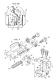
- FIG. 26 illustrates an example coupler 120 , an example gas delivery device 110 , and example components of oral appliance 100 .
- coupler 120 includes post 131 , clamps 128 , fasteners 126 , and swivel 122 .
- post 131 includes base 136 and arms 132 configured such that post 131 is substantially U-shaped.
- Other suitable shapes may be used in various embodiments.
- post 131 may be substantially V-shaped.
- FIGS. 27A-D illustrate an example embodiment of post 131 .
- arms 132 in the example embodiment extend at a substantially non-perpendicular angle to base 136 .
- angle 137 (relative to plane 138 extending substantially along the mating surface of base 136 ) is formed between the junction of base 136 and arms 132 .
- the positioning of arms 132 may provide for a variety of suitable configurations for post 131 .
- arms 132 may extend at an angle 137 between 60 and 80 degrees. Although any suitable angle 137 may be used, in a particular embodiment, arms 132 may extend substantially perpendicularly from base 136 . In the depicted embodiments, arms 132 include channels 130 . Channels 130 may be smooth as depicted in FIGS. 26 and 27B . In various embodiments, other suitable shapes may be used. For example, channels 130 may include one or more structures (e.g., notches) to facilitate positioning of clamps 128 .
- Post 131 may be formed of any suitable material, including suitable plastics or metals as examples. In certain embodiments, post 131 may be formed of 304 stainless steel.
- FIGS. 28A-29D show several perspectives of one embodiment of clamps 128 .
- clamps 128 comprise protrusions 129 .
- Protrusions 129 may be used to engage channels 130 , as described further below.
- Protrusions 129 may be configured differently in various embodiments.
- protrusions 129 may be configured to engage one or more structures in channels 130 to facilitate positioning of clamps 128 .
- Clamps 128 may also include threaded portions that facilitate advancement along channels 130 .
- Clamps 128 may be formed of any suitable material, including suitable plastics or metals as examples.
- clamps 128 may be formed of 304 stainless steel.
- fasteners 126 may be configured in a variety of manners such that fasteners 126 may be suitable for coupling to clamps 128 .
- Fasteners 126 may be threaded and the heads of fasteners 126 may be square, hexagonal, or any other appropriate shape to allow for a rotational force to be applied in order to secure fasteners 126 to clamps 128 .
- fasteners 126 may not be threaded.
- the ends of fasteners 126 may have notches or other structures that allow fasteners 126 to lock into place with clamps 128 .
- Fasteners 126 may be formed of any suitable material, including suitable plastics or metals as examples. In certain embodiments, fasteners 126 may be formed of 304 stainless steel.
- FIGS. 30A-D illustrate various embodiments of swivel 122 .
- swivel 122 is substantially spherical and includes opening 123 .
- opening 123 is substantially cylindrical while in the example of FIG. 30B , opening 123 includes a D-shaped passageway that may operate to index or orient gas delivery device 110 . Additionally, the D-shaped passageway may prevent rotation of swivel 122 relative to a post inserted into opening 123 .
- Other suitable configurations or shapes for opening 123 may be used.
- FIG. 30B illustrates an embodiment of swivel 122 wherein swivel 122 is substantially spherical with a flat top and bottom portion.
- Swivel 122 may, in various embodiments, take on other shapes, such as being substantially egg-shaped, and may or may not have a flat top and bottom. Swivel 122 may be formed of any suitable material, including suitable plastics or metals as examples. In particular embodiments, swivel 122 may be formed of acrylonitrile butadiene styrene (ABS) plastic or polycarbonate plastic.
- ABS acrylonitrile butadiene styrene
- coupler 120 may be coupled to body 12 through post 131 .
- base 136 may be fastened to body 12 through fastener passages 22 of body 12 and fastener passages 133 of base 136 using fasteners 20 .
- fasteners 20 may be any suitable technique.
- post 131 may be integrally formed with one or more components of oral appliance 100 .
- pins may be used to couple post 131 to oral appliance 100 .
- Clamps 128 may be used, in some embodiments, to secure swivel 122 to post 131 .
- Clamps 128 may be configured to slideably engage each arm 132 using channels 130 and protrusions 129 .
- Clamps 128 may be secured to arms 132 using fasteners 126 that, for example, pass through clamp 128 a , extend across the gap between arms 132 a and 132 b , and terminate at clamp 128 b . In such a manner, the position of swivel 122 relative to base 136 may be determined by the location of clamps 128 along channels 130 . Swivel 122 may be positioned between arms 132 and further secured by fasteners 126 .
- Swivel 122 may be secured by clamps 128 and fasteners 126 (as depicted in FIGS. 31A-B ) in a manner that allows swivel 122 to rotate along at least one axis.
- Swivel 122 may be configured to engage gas delivery device 110 .
- gas delivery device 110 may include coupling platform 112 .
- platform 112 and opening 123 may use the same shapes so as to facilitate coupling platform 112 to swivel 122 .
- coupling platform 112 may be shaped substantially cylindrically such that it may engage a substantially cylindrical opening 123 of swivel 122 .
- swivel 122 may be integrally formed with gas delivery device 110 or with other components such that no opening is required.
- swivel 122 includes a notch to allow swivel 122 to be compressed to adjust the diameter of opening 123 .
- Rotating swivel 122 while it is secured to post 131 and platform 112 may allow gas delivery device to be positioned in a suitable manner to properly fit to a patient's face.
- the freedom of movement allowed by coupler 120 allows gas delivery device 110 to be comfortably and effectively fitted to the patient's unique facial features and preferences. Once they are so fitted, fasteners 126 are tightened so as to maintain this comfortable and effective orientation between gas delivery device 110 and oral appliance 100 .
- gas delivery device 110 may be further positioned while being secured to platform 112 by moving swivel 122 closer to or away from base 136 of post 131 . This, in some embodiments, may be accomplished by sliding clamps 128 along channels 130 .
- oral appliance 100 will be securely in place in the patient's mouth. Because it is connected to gas delivery device 110 through coupler 120 , oral appliance 100 acts as an anchor, maintaining the orientation and fit of gas delivery device 110 .
- coupler 120 may also be used with oral appliances that do not perform this function.
- example oral appliance 100 is used with coupler 120 to anchor gas delivery device 110 .
- other oral appliances may be used to anchor a gas delivery device.
- an upper arch alone could be used with coupler 120 to connect to gas delivery device 110 .
- oral appliances not shaped as arches could also be used with coupler 120 .
- the term oral appliance is meant to include any device which can fit within the oral cavity and serve as an anchor for the gas delivery device.
- coupler 120 may be formed of any suitable material, including suitable plastics or metals as examples.
- post 131 and clamps 128 may be formed of 304 stainless steel.
- Fasteners 126 may include threaded fasteners, pins, or any other appropriate fastener to couple clamps 128 to arms 132 .
- FIG. 27C illustrates passageway 134 which may allow items such as key 80 and post 90 to pass through so that oral appliance 10 may be adjusted while coupled to coupler 120 .
- adjustment key 80 may be inserted through passageway 134 while swivel 122 is engaged or disengaged from post 131 in order to adjust oral appliance 10 (as described above) even though post 131 is secured to body 12 .
- FIG. 31 illustrate embodiments of coupler 120 including sleeve 140 .
- Sleeve 140 in the depicted embodiments, covers a portion of coupler 120 .
- sleeve 140 may be made out of rubber, silicon, or other suitable materials.
- Sleeve 140 may be used to enhance the comfort and/or safety of a user of oral appliance 100 and gas delivery device 110 .
- sleeve 140 may help protect portions of a user's mouth or face from being irritated by the use of coupler 120 .
- FIG. 32 illustrates an example method of improving a user's breathing, indicated generally at 200 .
- upper arch 102 is inserted into the user's mouth.
- lower arch 104 is inserted into the user's mouth.
- upper arch 102 is coupled to lower arch 104 by adjustment mechanism 10 .
- adjustment mechanism 10 includes a body 12 coupled to upper arch 102 , an adjustor 36 , a hook 28 , and a receiver 50 coupled to lower arch 104 .
- upper arch 102 is coupled to lower arch 104 by engaging shelf 54 of receiver 50 with arm 46 of hook 28 .
- the initial forward position of lower arch 104 relative to upper arch 102 is determined by engaging a particular one of multiple shelves 54 of receiver 50 .
- the initial forward position of lower arch 104 relative to upper arch 102 is determined by engaging shelf 68 of extender 60 coupled to receiver 50 .
- the forward position of lower arch 104 relative to upper arch 102 is adjusted to facilitate improved breathing by the user.
- the forward position is adjusted by rotating adjustor 36 using adjustment key 80 or in any other appropriate manner.
- FIG. 33 illustrates an example method of coupling a gas delivery device to an oral appliance, indicated generally at 210 .
- gas delivery device 110 is coupled to oral appliance 100 .
- gas delivery device 110 may be coupled to oral appliance 100 using coupler 120 with arms 132 , clamps 128 , and swivel 122 .
- swivel 122 may couple to gas delivery device 110 at mounting platform 112 .
- gas delivery device 110 is positioned. This may be done by adjusting clamps 128 along channels 130 .
- swivel 122 may be adjusted in order to further refine the position of gas delivery device 110 . In certain embodiments, this may include rotating swivel 122 about at least one axis while swivel 122 is positioned between clamps 128 .
- gas delivery device 110 is secured. This may be accomplished by tightening fasteners 126 so that clamps 128 are secured to arms 132 . Tightening fasteners 126 may also secure the position of swivel 122 , thus securing the orientation of gas delivery device 110 . In some embodiments, this may cause gas delivery device 110 to be positioned appropriately for the user by orienting swivel 122 to post 131 . In certain embodiments, post 131 may be coupled to oral appliance 100 at body 12 .
- inserting the upper and lower arches can be accomplished sequentially, in any order, or simultaneously.
- upper arch 102 and lower arch 104 may be coupled subsequent to or prior to inserting upper arch 102 and lower arch 104 into the user's mouth.
- the adjustment of the forward position of lower arch 104 relative to upper arch 102 may be performed in measured increments interspersed with trial periods to test the effectiveness of the oral appliance in improving the user's breathing.
- Method 200 may include checking or verifying the forward position of lower arch 104 relative to upper arch 102 and then repeating step 208 as needed.
- method 200 may include checking or verifying the position of gas delivery device 110 relate to the user and then repeating steps 208 and 210 as needed.
- the present invention contemplates using methods with additional steps, fewer steps, or different steps, so long as the methods remain appropriate for improving a user's breathing.
Abstract
Description
Claims (8)
Priority Applications (1)
| Application Number | Priority Date | Filing Date | Title |
|---|---|---|---|
| US12/712,931 US8607796B2 (en) | 2009-02-27 | 2010-02-25 | Apparatus and method for coupling an oral appliance to a gas delivery device |
Applications Claiming Priority (2)
| Application Number | Priority Date | Filing Date | Title |
|---|---|---|---|
| US15632309P | 2009-02-27 | 2009-02-27 | |
| US12/712,931 US8607796B2 (en) | 2009-02-27 | 2010-02-25 | Apparatus and method for coupling an oral appliance to a gas delivery device |
Publications (2)
| Publication Number | Publication Date |
|---|---|
| US20100218773A1 US20100218773A1 (en) | 2010-09-02 |
| US8607796B2 true US8607796B2 (en) | 2013-12-17 |
Family
ID=42666458
Family Applications (1)
| Application Number | Title | Priority Date | Filing Date |
|---|---|---|---|
| US12/712,931 Expired - Fee Related US8607796B2 (en) | 2009-02-27 | 2010-02-25 | Apparatus and method for coupling an oral appliance to a gas delivery device |
Country Status (1)
| Country | Link |
|---|---|
| US (1) | US8607796B2 (en) |
Cited By (8)
| Publication number | Priority date | Publication date | Assignee | Title |
|---|---|---|---|---|
| US20130014767A1 (en) * | 2010-03-16 | 2013-01-17 | Heinberger Handelsbolag | Device in connection with sleep apnoea |
| US8807139B1 (en) * | 2012-09-21 | 2014-08-19 | Kris A. Kostrzewski | Oral air delivery system for CPAP |
| US20140290668A1 (en) * | 2013-03-28 | 2014-10-02 | W. Keith Thornton | Adjustable Breathing Device |
| US10010313B2 (en) | 2015-05-18 | 2018-07-03 | Richard L. Arden | Mandibular subluxation device and method |
| US10258319B2 (en) | 2015-05-18 | 2019-04-16 | Richard L. Arden | Airway assist device and method |
| US10342526B2 (en) | 2015-07-01 | 2019-07-09 | Richard L. Arden | Airway assist device and method |
| US10632274B2 (en) | 2016-04-28 | 2020-04-28 | Jeffrey Norsted | CPAP mask attachment system |
| US10905837B2 (en) | 2015-04-02 | 2021-02-02 | Hill-Rom Services Pte. Ltd. | Respiratory therapy cycle control and feedback |
Families Citing this family (11)
| Publication number | Priority date | Publication date | Assignee | Title |
|---|---|---|---|---|
| US8333202B2 (en) * | 2009-03-24 | 2012-12-18 | Donald R. Lyons, Jr. | Adjustable dental device for treatment of sleep apnea and snoring |
| US8684006B2 (en) * | 2010-03-26 | 2014-04-01 | Advanced Brain Monitoring, Inc. | Systems and methods for optimizing oral appliance therapy for the treatment of sleep apnea |
| US8783250B2 (en) | 2011-02-27 | 2014-07-22 | Covidien Lp | Methods and systems for transitory ventilation support |
| US9993604B2 (en) | 2012-04-27 | 2018-06-12 | Covidien Lp | Methods and systems for an optimized proportional assist ventilation |
| US9375542B2 (en) | 2012-11-08 | 2016-06-28 | Covidien Lp | Systems and methods for monitoring, managing, and/or preventing fatigue during ventilation |
| US9358355B2 (en) | 2013-03-11 | 2016-06-07 | Covidien Lp | Methods and systems for managing a patient move |
| AU2018299419B2 (en) * | 2017-07-11 | 2023-05-18 | Stewart Cullen | Mandibular advancement splint |
| CN110049799B (en) | 2017-11-14 | 2022-04-26 | 柯惠有限合伙公司 | Method and system for driving pressure spontaneous ventilation |
| US11517691B2 (en) | 2018-09-07 | 2022-12-06 | Covidien Lp | Methods and systems for high pressure controlled ventilation |
| TWM585155U (en) * | 2019-02-27 | 2019-10-21 | 台灣基督長老教會馬偕醫療財團法人馬偕紀念醫院 | Breathing mask |
| US11065410B1 (en) * | 2021-02-01 | 2021-07-20 | Leonard Feld | Dental appliance using airway dialation for treating covid related breathing disorders |
Citations (267)
| Publication number | Priority date | Publication date | Assignee | Title |
|---|---|---|---|---|
| US339334A (en) | 1886-04-06 | Peocess of maeihg a eeveesed profile patteen of the | ||
| US690663A (en) | 1901-08-16 | 1902-01-07 | Harry Pratt | Appliance for swimmers. |
| US746869A (en) | 1903-08-05 | 1903-12-15 | Stillman Augustus Moulton | Device for preventing snoring. |
| US774446A (en) | 1904-05-19 | 1904-11-08 | Stillman Augustus Moulton | Device for preventing snoring. |
| US781516A (en) | 1904-02-03 | 1905-01-31 | George N Guthrie Jr | Respirator and inhaler. |
| US885196A (en) | 1906-10-08 | 1908-04-21 | Henry Steil | Antisnoring-shield. |
| US893213A (en) | 1908-03-14 | 1908-07-14 | William T Whiteway | Respirator. |
| US955562A (en) | 1909-05-06 | 1910-04-19 | Gertrude W Thomas | Chin-mask. |
| US996783A (en) | 1910-08-22 | 1911-07-04 | Hector L Moreau | Process of making sculptors' molds. |
| US1076534A (en) | 1913-01-23 | 1913-10-21 | Firman Tullock Wallen | Dental instrument. |
| US1146264A (en) | 1914-07-08 | 1915-07-13 | Will S Kelly | Dental splint. |
| US1483694A (en) | 1921-02-02 | 1924-02-12 | Albert F Stukey | Breathing corrector |
| US1592345A (en) | 1915-12-15 | 1926-07-13 | Drager Alexander Bernhard | Mouthpiece for respiratory apparatus |
| US1649664A (en) | 1927-01-06 | 1927-11-15 | Moscow B Carter | Bite meter |
| US1674336A (en) | 1927-10-27 | 1928-06-19 | King Edward John | Respirator |
| US1675202A (en) | 1926-02-08 | 1928-06-26 | Flavius J Sanders | Method of making plastic casts |
| US1679748A (en) | 1927-02-23 | 1928-08-07 | Ray A Stratton | Dental appliance for indicating the outline of the face |
| US2171695A (en) | 1939-02-08 | 1939-09-05 | Robert N Harper | Method and apparatus for procuring impressions of the surfaces of the anterior teeth or dental work |
| US2178128A (en) | 1937-03-20 | 1939-10-31 | Warren A Casey | Antisnoring device |
| US2383649A (en) | 1941-08-23 | 1945-08-28 | Air Reduction | Breathing mask for parachute escape devices |
| US2424533A (en) | 1945-07-21 | 1947-07-22 | Faires William Jay | Antisnore device |
| US2505028A (en) | 1947-11-17 | 1950-04-25 | Surgident Ltd | Syringe for applying heat-fluent impression composition to dental inlay preparationsand the like, and impression-material cartridge for use therein |
| US2521084A (en) | 1949-09-01 | 1950-09-05 | William T Oberto | Mandible cushion for oxygen masks |
| US2521039A (en) | 1949-03-16 | 1950-09-05 | Victor H Carpenter | Tooth guard |
| US2531222A (en) | 1946-11-25 | 1950-11-21 | Harold D Kesling | Tooth positioning appliance |
| US2574623A (en) | 1948-01-31 | 1951-11-13 | Clyde Martin | Antisnoring device |
| US2590118A (en) | 1949-10-01 | 1952-03-25 | Jr Vincent J Oddo | Mouthpiece |
| US2627268A (en) | 1951-03-02 | 1953-02-03 | Elsa L Leppich | Antisnoring device |
| US2671446A (en) | 1952-10-28 | 1954-03-09 | Ann S V Mann | Beauty mask |
| US2712160A (en) | 1955-07-05 | Method of making individual bowling | ||
| US2833278A (en) | 1956-04-05 | 1958-05-06 | Harold M Ross | Protective mouthpiece |
| US2867212A (en) | 1957-12-27 | 1959-01-06 | Jr William A Nunn | Snore stopping mouthpiece and process of making same |
| US2882893A (en) | 1957-05-23 | 1959-04-21 | Nicholas A C Godfroy | Combination mouth piece and air-way |
| US2917045A (en) | 1958-12-10 | 1959-12-15 | Air Reduction | Face mask and similar devices having body-conforming means |
| US2977636A (en) | 1958-08-05 | 1961-04-04 | Robert D Mcguire | Method of molding a hollow rubber article |
| US3037501A (en) | 1959-02-02 | 1962-06-05 | Scott Aviation Corp | Quick-donning breathing mask |
| US3064354A (en) | 1959-12-03 | 1962-11-20 | Irving Kayton | Devices and methods for dental bites and impressions |
| US3107668A (en) | 1962-07-17 | 1963-10-22 | Junior W Thompson | Method of forming a tooth protector |
| US3124129A (en) | 1964-03-10 | Teeth protector | ||
| US3132647A (en) | 1962-04-19 | 1964-05-12 | Corniello Giuseppe | Anti-snoring device |
| US3219033A (en) | 1963-06-06 | 1965-11-23 | Wallshein Melvin | Thumb-sucking and tongue-thrusting deterring device |
| US3277892A (en) | 1966-01-06 | 1966-10-11 | Tepper Harry William | Apparatus for correcting tongue thrust problems |
| US3312216A (en) | 1963-07-22 | 1967-04-04 | Wallshein Melvin | Tongue-thrusting inhibiting devices |
| US3321832A (en) | 1963-08-26 | 1967-05-30 | Dentists Supply Co | Dental articulator analogs and method and apparatus for constructing same |
| US3330274A (en) | 1964-10-15 | 1967-07-11 | Puritan Compressed Gas Corp | Oro-nasal face mask with improved pneumatic sealing cuff |
| US3360860A (en) | 1963-09-23 | 1968-01-02 | John H. Roland | Apparatus for preparing impressions of the mandibular dentition |
| US3434470A (en) | 1966-05-27 | 1969-03-25 | James C Strickland | Snore inhibiting device |
| US3457916A (en) | 1966-12-30 | 1969-07-29 | Personalized Equipment Inc | Protective mouthpiece |
| US3513838A (en) | 1967-10-11 | 1970-05-26 | John W Foderick | Teeth protector |
| US3522805A (en) | 1968-03-04 | 1970-08-04 | Melvin Wallshein | Dental appliances for inhibiting tonguethrusting and thumb-sucking |
| US3658058A (en) | 1970-04-06 | 1972-04-25 | Mine Safety Appliances Co | Breathing apparatus nose-closing device |
| US3690004A (en) | 1971-03-08 | 1972-09-12 | John P Frush | Impression tray and method for making impressions |
| US3695265A (en) | 1970-10-26 | 1972-10-03 | Elmer Lawrence Brevik | Face mask |
| US3845768A (en) | 1970-09-21 | 1974-11-05 | R Garrahan | Form fit vertical flow diving head gear |
| US3854208A (en) | 1973-01-19 | 1974-12-17 | G Arant | Dental face bow assembly |
| US3864832A (en) | 1972-04-05 | 1975-02-11 | Gunnar Olof Carlson | Throw-away teeth protector |
| US3871370A (en) | 1973-07-05 | 1975-03-18 | Lee E Mcdonald | Tongue-thrust correction appliance |
| US3882601A (en) | 1973-03-06 | 1975-05-13 | Kettenbach Fa A | Interstice device for denture double impressions |
| US3884226A (en) | 1973-09-13 | 1975-05-20 | Harry W Tepper | Apparatus for correcting tongue thrust |
| US4016650A (en) | 1974-11-15 | 1977-04-12 | Bayer Aktiengesellschaft | Impression tray for dental purposes |
| US4026024A (en) | 1975-10-20 | 1977-05-31 | Michael Tradowsky | Vise for transfer of check-bites |
| DE2320501C3 (en) | 1973-04-21 | 1978-08-24 | Hugo Dr.Med.Dent. 7000 Stuttgart Stockfisch | Device for reducing the sound of breathing during sleep |
| US4114614A (en) | 1976-11-19 | 1978-09-19 | Kesling Peter C | Athletic mouthguard |
| US4169473A (en) | 1978-03-03 | 1979-10-02 | Samelson Charles F | Anti-snoring and anti-bruxism device |
| US4182312A (en) | 1977-05-20 | 1980-01-08 | Mushabac David R | Dental probe |
| GB1569129A (en) | 1977-07-19 | 1980-06-11 | Rata M A | Anti-snoring device |
| US4227877A (en) | 1977-10-20 | 1980-10-14 | Black Knight Investments, Limited | Anatomical intra-orally moldable dental impression tray and method |
| US4233972A (en) | 1978-05-08 | 1980-11-18 | Wolfgang Hauff | Portable air filtering and breathing assist device |
| US4258710A (en) | 1978-08-16 | 1981-03-31 | Reber Fred L | Mask-type respirator |
| US4289127A (en) | 1979-10-29 | 1981-09-15 | Nelson Byron G | Breathing apparatus stabilizer |
| GB2072567A (en) | 1980-03-25 | 1981-10-07 | Butler M P | Forms for investment casting and products produced therefrom |
| US4294243A (en) | 1978-12-08 | 1981-10-13 | The United States Of America As Represented By The Secretary Of The Air Force | Respirators |
| US4304227A (en) | 1978-03-03 | 1981-12-08 | Samelson Charles F | Device for treatment of snoring, bruxism or for avoidance of sleep apnea |
| US4345592A (en) | 1980-09-10 | 1982-08-24 | A-T-O Inc. | Pressure demand regulator with automatic shut-off |
| US4345593A (en) | 1978-07-19 | 1982-08-24 | A-T-O Inc. | Pressure-demand breathing apparatus with automatic air shut-off |
| US4376628A (en) | 1979-05-09 | 1983-03-15 | B.V. Gaba | Device for treating teeth |
| US4382783A (en) | 1982-06-28 | 1983-05-10 | Rosenberg Farel A | Intraoral dental appliance to correct retrusive mandibles orthopedically in the treatment of Class II malocclusions |
| US4392490A (en) | 1981-02-23 | 1983-07-12 | Mattingly Glen R | Multiple outlet connecting means for self-contained positive pressure or demand regulated breathing apparatus |
| US4397701A (en) | 1981-02-20 | 1983-08-09 | International Mask Research Foundation | Method of making masks |
| US4419992A (en) | 1981-02-12 | 1983-12-13 | Chorbajian Peter M | Occlusal splints and the method of manufacturing the same |
| US4433956A (en) | 1981-07-27 | 1984-02-28 | Witzig John W | Orthopedic corrector and method of correction of Class II malocclusion |
| US4439149A (en) | 1982-09-16 | 1984-03-27 | John Devincenzo | Vertically-indexed posterior bite plates |
| US4439147A (en) | 1981-01-02 | 1984-03-27 | Magill Thomas S | Bite-taking device |
| US4454090A (en) | 1983-09-26 | 1984-06-12 | International Flavors & Fragrances Inc. | Method of forming the bridge portion in a frame for eyeglasses |
| US4470413A (en) | 1982-01-29 | 1984-09-11 | Dr/a/ gerwerk Aktiengesellschaft | Protective breathing apparatus including a mask and mouthpiece |
| US4495945A (en) | 1982-03-29 | 1985-01-29 | Liegner Kenneth B | Bite block |
| US4505672A (en) | 1983-11-14 | 1985-03-19 | Kurz Craven H | Two-piece gnathologic orthodontic positioner |
| US4530662A (en) | 1983-04-26 | 1985-07-23 | Andersson A E Bror | Impression tray for dental purposes |
| US4553549A (en) | 1984-10-09 | 1985-11-19 | Pope Bryan M | Oral orthopedic/orthodontic appliance for treating neuromuscular imbalance |
| US4568280A (en) | 1983-06-13 | 1986-02-04 | Ahlin Jeffrey H | Craniomandibular appliance |
| US4569342A (en) | 1982-10-20 | 1986-02-11 | Nostitz F Von | Dental impression tray and process for the use thereof |
| US4593686A (en) | 1984-11-13 | 1986-06-10 | Lloyd Stephen R | Monitor for an anti-apnea device |
| US4602905A (en) | 1985-03-26 | 1986-07-29 | Keefe Iii John T O | Dental impression registration device |
| US4639220A (en) | 1982-11-29 | 1987-01-27 | Nippon Avionics Co., Ltd. | Apparatus for determining the three-dimensional position and attitude |
| US4655213A (en) | 1983-10-06 | 1987-04-07 | New York University | Method and apparatus for the treatment of obstructive sleep apnea |
| US4668188A (en) | 1986-01-29 | 1987-05-26 | Wolfenson Gilbert B | Oral impression tray for forming a mouthguard |
| US4669459A (en) | 1985-11-29 | 1987-06-02 | Spiewak Martin H | Anti-snoring device |
| DE3543931A1 (en) | 1985-12-12 | 1987-06-19 | Ruediger Dr Dinse | Breathing mask |
| US4676240A (en) | 1985-09-09 | 1987-06-30 | Gardy Victor R | Tongue locking device to minimize effects of sleep apnea and to reduce snoring |
| US4706683A (en) | 1985-12-20 | 1987-11-17 | Bowman Gray School Of Medicine, Wake Forest University | Method and apparatus for bolus delivery of gases and aerosols and insufflations |
| US4715368A (en) | 1986-08-06 | 1987-12-29 | George Peter T | Nocturnal airway-patency appliance |
| US4741696A (en) | 1986-09-25 | 1988-05-03 | Gac International, Inc. | Orthodontic appliances for dental arch expansion |
| DE3707952A1 (en) | 1987-03-12 | 1988-09-22 | Ernst Dipl Ing Hoermann | Breathing mask for long-term operation |
| US4773853A (en) | 1987-11-09 | 1988-09-27 | Leon Kussick | Oral orthopedic appliance |
| US4784123A (en) | 1986-01-03 | 1988-11-15 | Union Carbide Corporation | Orthopedic/orthotic splint materials |
| DE3719009A1 (en) | 1987-06-06 | 1988-12-22 | Ernst Dipl Ing Hoermann | Ventilation mask with adjustable mouthpiece and nose moulding |
| US4799500A (en) | 1986-09-17 | 1989-01-24 | Newbury Renton D | Method of and apparatus for treatment of muscle imbalance |
| EP0312368A1 (en) | 1987-10-13 | 1989-04-19 | HAYS & MEADE, INC. | A device for preventing snoring |
| US4858606A (en) | 1986-10-09 | 1989-08-22 | Normalair-Garrett (Holding) Systems | Low pressure breathing regulators and breathing gas systems incorporating the same |
| US4858605A (en) | 1986-04-25 | 1989-08-22 | Jay Danziger | Oral artificial ventilation apparatus |
| US4862903A (en) | 1987-10-09 | 1989-09-05 | U.S. Divers Company, Inc. | Breathing mouthpiece for contacting upper palate and lower jaw of user's mouth |
| US4870962A (en) | 1987-09-14 | 1989-10-03 | Lee Sitnik | Disposable self-inflating manual resuscitator bag |
| US4886056A (en) | 1988-03-21 | 1989-12-12 | Sabre Safety Limited | Breathing apparatus |
| US4892478A (en) | 1988-03-21 | 1990-01-09 | Dentsply Research & Development Corp. | Method of preparing dental appliances |
| US4901737A (en) | 1987-04-13 | 1990-02-20 | Toone Kent J | Method and therapeutic apparatus for reducing snoring |
| US4906234A (en) | 1989-01-09 | 1990-03-06 | Voychehovski Tomasz H | Medical tube holder |
| EP0359135A1 (en) | 1988-09-08 | 1990-03-21 | Sunstar Kabushiki Kaisha | Mouthpiece |
| US4919128A (en) | 1988-08-26 | 1990-04-24 | University Technologies International Inc. | Nasal adaptor device and seal |
| US4932867A (en) | 1988-01-25 | 1990-06-12 | Chugoku Shiken Kabushiki Kaisha | Device and process for determining jaws position |
| US4941212A (en) | 1980-04-25 | 1990-07-17 | Liff Lawrence J | Method of making a face mask and applying the face mask to the head |
| US4955393A (en) | 1988-03-30 | 1990-09-11 | Trident Laboratories, Inc. | Mouthguard with conformable arch liners |
| USRE33442E (en) | 1986-08-06 | 1990-11-20 | Nocturnal airway-patency appliance | |
| US5003994A (en) | 1989-10-10 | 1991-04-02 | Cook George W | Oral appliance for improving breathing and methods of using and making same |
| US5011407A (en) | 1989-05-22 | 1991-04-30 | Joseph Pelerin | Custom dental impression tray |
| US5018533A (en) | 1989-05-25 | 1991-05-28 | Hawkins Richard H | Apparatus for the reduction of apnaa in the edentulous |
| US5026278A (en) | 1990-02-23 | 1991-06-25 | Minnesota Mining And Manufacturing Company | Dental impression tray with flange |
| US5028232A (en) | 1989-05-03 | 1991-07-02 | Snow Michael D | Apparatus and method for calibrating physiologic dental occlusion and determining optimal individual orthodontic appliance prescription |
| US5040976A (en) | 1990-02-23 | 1991-08-20 | Minnesota Mining And Manufacturing Company | Expandable dental impression tray |
| US5042478A (en) | 1988-08-26 | 1991-08-27 | University Technologies International, Inc. | Method of ventilation using nares seal |
| US5042506A (en) | 1989-11-02 | 1991-08-27 | Liberati Salvator P | Antisnoring training device |
| FR2658725A1 (en) | 1990-02-26 | 1991-08-30 | Barthou Gilles | Method for producing a nasal orthesis, and nasal mask comprising such an orthesis |
| US5046512A (en) | 1989-03-10 | 1991-09-10 | Murchie John A | Method and apparatus for treatment of snoring |
| US5052409A (en) | 1989-05-08 | 1991-10-01 | Tepper Harry W | Oral appliance for tongue thrust correction |
| US5055039A (en) | 1988-10-06 | 1991-10-08 | Great Lakes Orthodontics, Ltd. | Orthodontic positioner and methods of making and using same |
| US5056534A (en) | 1987-07-08 | 1991-10-15 | Wright David W R | Snore inhibiting device |
| US5062421A (en) | 1987-11-16 | 1991-11-05 | Minnesota Mining And Manufacturing Company | Respiratory mask having a soft, compliant facepiece and a thin, rigid insert and method of making |
| US5064371A (en) | 1991-03-26 | 1991-11-12 | Smeltzer Marsha F | Dental impression tray |
| US5066231A (en) | 1990-02-23 | 1991-11-19 | Minnesota Mining And Manufacturing Company | Dental impression process using polycaprolactone molding composition |
| US5065756A (en) | 1987-12-22 | 1991-11-19 | New York University | Method and apparatus for the treatment of obstructive sleep apnea |
| US5078600A (en) | 1990-06-25 | 1992-01-07 | Austin David G | Multifunction mandibular movement measuring device |
| US5092346A (en) | 1987-10-13 | 1992-03-03 | Hays & Meade, Inc. | Dental orthosis for alleviation of snoring |
| US5103838A (en) | 1990-02-09 | 1992-04-14 | Yousif Edward N | Dental night guard |
| US5112225A (en) | 1991-08-02 | 1992-05-12 | Michael Diesso | Custom dental tray |
| US5117816A (en) | 1991-01-03 | 1992-06-02 | Shapiro Norman A | Anti-snore device |
| US5154184A (en) | 1991-09-16 | 1992-10-13 | Alvarez Ramiro M | Adjustable anti-snoring apparatus |
| US5154609A (en) | 1991-07-16 | 1992-10-13 | George Peter T | Instrument for registration of the dental bite |
| US5183057A (en) | 1991-07-30 | 1993-02-02 | Syrop Steven B | Fluid motion device (FMD) for exercising the temporomandibular joint |
| US5188529A (en) | 1990-05-10 | 1993-02-23 | Girrbach Dental Gmbh | Device for static fixation of the jaw relation |
| US5190457A (en) | 1991-05-17 | 1993-03-02 | Josephus Schreinemakers | Method for making an impression of a dentate human jaw |
| US5193532A (en) | 1988-12-06 | 1993-03-16 | Moa Conny P G | Device for generating by means of ejector action a continuous positive airway pressure (cpap) during spontaneous breathing |
| US5213498A (en) | 1990-05-01 | 1993-05-25 | Advantage Dental Products, Inc. | Method for making a custom impression tray |
| US5233978A (en) | 1992-04-03 | 1993-08-10 | Medway | Nasal oxygen mask |
| US5243971A (en) | 1990-05-21 | 1993-09-14 | The University Of Sydney | Nasal mask for CPAP having ballooning/moulding seal with wearer's nose and facial contours |
| US5245995A (en) | 1987-06-26 | 1993-09-21 | Rescare Limited | Device and method for monitoring breathing during sleep, control of CPAP treatment, and preventing of apnea |
| US5265595A (en) | 1989-06-19 | 1993-11-30 | Hans Rudolph, Inc. | Mask for breath analysis |
| US5267862A (en) | 1993-01-08 | 1993-12-07 | Parker Jonathan A | Intraoral appliance |
| US5267557A (en) | 1992-08-17 | 1993-12-07 | Her Mou Lin | Nose mask with a filtering device |
| US5277202A (en) | 1992-08-26 | 1994-01-11 | Mb Hays, Inc. | Easy fit anti-snoring device |
| US5284161A (en) | 1992-11-12 | 1994-02-08 | Karell Manuel L | Snopper-the snoring stopper anti-snoring mouth device |
| US5313960A (en) | 1992-11-04 | 1994-05-24 | Marc S. Bernstein | Apparatus and method for reducing snoring and method of making same |
| US5316020A (en) | 1990-10-03 | 1994-05-31 | Ernest Truffer | Snoring prevention device |
| US5320533A (en) | 1992-02-12 | 1994-06-14 | Lee Robert L | Fixed prosthodontic tool kit and method for placing and fitting crowns and inlays |
| US5336086A (en) | 1993-11-05 | 1994-08-09 | Coltene/Whaledent, Inc. | Dental impression tray |
| US5365945A (en) | 1993-04-13 | 1994-11-22 | Halstrom Leonard W | Adjustable dental applicance for treatment of snoring and obstructive sleep apnea |
| US5370533A (en) | 1993-11-08 | 1994-12-06 | Bushnell; Raymond B. | Dental impression tray assembly and method of taking impressions |
| US5373859A (en) | 1993-04-19 | 1994-12-20 | Forney; Leroy S. | Tongue positioning device |
| US5392773A (en) | 1994-04-13 | 1995-02-28 | Bertrand; Archie A. | Respiratory particulate filter |
| US5409017A (en) | 1994-01-19 | 1995-04-25 | The University Of British Columbia | Mandible repositioning appliance |
| US5415544A (en) | 1990-02-23 | 1995-05-16 | Minnesota Mining And Manufacturing Company | Preloaded thermoplastic dental impression tray |
| US5427117A (en) | 1993-09-29 | 1995-06-27 | Thornton; W. Keith | Apparatus for prevention of snoring and improved breathing during sleep |
| US5456264A (en) | 1994-03-31 | 1995-10-10 | Universite Laval | Accuracy of breath-by-breath analysis of flow volume loop in identifying flow-limited breathing cycles in patients |
| US5458137A (en) | 1991-06-14 | 1995-10-17 | Respironics, Inc. | Method and apparatus for controlling sleep disorder breathing |
| US5474060A (en) | 1993-08-23 | 1995-12-12 | Evans; David | Face mask with gas sampling port |
| US5477850A (en) | 1992-10-06 | 1995-12-26 | Rockwell International Corp. | Integrated buoyancy suit crew protection system with +/-GZ protection |
| US5499633A (en) | 1993-12-17 | 1996-03-19 | Fenton; Douglas F. | Anti-snoring device with adjustable upper and lower relational members |
| US5503146A (en) | 1994-10-26 | 1996-04-02 | Devilbiss Health Care, Inc. | Standby control for CPAP apparatus |
| US5503552A (en) | 1993-11-18 | 1996-04-02 | Diesso; Michael | Dental impression method and composition |
| US5517983A (en) | 1992-12-09 | 1996-05-21 | Puritan Bennett Corporation | Compliance meter for respiratory therapy |
| US5537999A (en) | 1991-04-03 | 1996-07-23 | Bnos Electronics Limited | Breathing apparatus |
| US5538000A (en) | 1995-02-06 | 1996-07-23 | Hans Rudolph, Inc. | Airflow delivery system |
| US5538014A (en) | 1994-01-10 | 1996-07-23 | James W. Wilson | Deformable face shield with mouthpiece |
| US5537994A (en) | 1994-06-03 | 1996-07-23 | Thornton; W. Keith | Combination face mask and dental device for improved breathing during sleep |
| US5540223A (en) | 1994-02-17 | 1996-07-30 | Respironics, Inc. | Respiratory mask facial seal |
| US5551872A (en) | 1994-09-30 | 1996-09-03 | Mena; Raul | Dental impression device |
| US5551419A (en) | 1994-12-15 | 1996-09-03 | Devilbiss Health Care, Inc. | Control for CPAP apparatus |
| US5558090A (en) | 1995-10-30 | 1996-09-24 | James; Lonnie A. | Multi-purpose head-mounted adjustable medical tube holder |
| US5560354A (en) | 1993-06-18 | 1996-10-01 | Rescare Limited | Facial masks for assisted respiration or CPAP |
| US5562449A (en) | 1995-04-18 | 1996-10-08 | Jacobs; Allison J. | Custom dental tray |
| US5570704A (en) | 1993-10-28 | 1996-11-05 | Snoreless Corp | Universal, user-adjustable oral cavity appliance to control snoring and reduce episodes of obstructive sleep apnea |
| US5582517A (en) | 1993-04-29 | 1996-12-10 | Adell; Loren S. | Multi-laminar dental impression tray assembly |
| US5592935A (en) | 1995-05-03 | 1997-01-14 | Minnesota Mining And Manufacturing Company | Positive/negative air pressure adaptor for use with respirators |
| US5611485A (en) | 1994-08-12 | 1997-03-18 | William W. Gibbs | Method and apparatus for dispensing a substance |
| US5657751A (en) | 1993-07-23 | 1997-08-19 | Karr, Jr.; Michael A. | Cardiopulmonary resuscitation unit |
| US5657752A (en) | 1996-03-28 | 1997-08-19 | Airways Associates | Nasal positive airway pressure mask and method |
| US5662101A (en) | 1995-12-07 | 1997-09-02 | Respironics, Inc. | Respiratory facial mask |
| FR2731624B1 (en) | 1995-03-16 | 1997-09-26 | Assist Publ Hopitaux De Paris | FACE VENTILATION MASK, PART AND METHOD FOR THE PRODUCTION THEREOF |
| US5676133A (en) | 1995-06-14 | 1997-10-14 | Apotheus Laboratories, Inc. | Expiratory scavenging method and apparatus and oxygen control system for post anesthesia care patients |
| US5678567A (en) | 1994-03-25 | 1997-10-21 | Thornton; W. Keith | Apparatus for adjusting a dental device |
| US5681164A (en) | 1993-07-22 | 1997-10-28 | Bass; Neville Meyer | Orthodontic appliance |
| US5687715A (en) | 1991-10-29 | 1997-11-18 | Airways Ltd Inc | Nasal positive airway pressure apparatus and method |
| US5713349A (en) | 1993-06-02 | 1998-02-03 | Keaney; Niall | Inhalation therapy |
| US5718500A (en) | 1995-09-23 | 1998-02-17 | Vinci Guerra; Mark T. | Positive pressure impact resistant lens for improved vision and safety |
| US5718244A (en) | 1996-08-05 | 1998-02-17 | Thornton; W. Keith | External ear occlusion device having an improved deformable material and metod for forming same |
| US5720302A (en) | 1996-03-01 | 1998-02-24 | Belfer; William A. | Anti-snoring device having an external shield |
| US5724965A (en) | 1995-06-06 | 1998-03-10 | Respironics Inc. | Nasal mask |
| US5746201A (en) | 1997-01-23 | 1998-05-05 | Nellcor Puritan-Bennett | CPAP nose mask |
| US5752510A (en) | 1996-11-14 | 1998-05-19 | Goldstein; Joseph | Nasal and oral air passageway delivery management apparatus |
| US5807100A (en) | 1996-05-24 | 1998-09-15 | Thornton; W. Keith | Dental device having an improved deformable material and method for forming same |
| US5810749A (en) | 1996-05-21 | 1998-09-22 | Maas; Corey S. | Nasal fixation with water-hardening fiber-mesh resin |
| US5829441A (en) | 1997-06-24 | 1998-11-03 | Nellcor Puritan Bennett | Customizable dental device for snoring and sleep apnea treatment |
| US5832918A (en) | 1996-12-20 | 1998-11-10 | Pantino; Don A. | Method of making a face mask from a facial impression and of gas delivery |
| US5846082A (en) | 1996-05-24 | 1998-12-08 | Thornton; W. Keith | System and method for customizing a dental device using an improved deformable material |
| US5887587A (en) | 1994-12-07 | 1999-03-30 | Edentec Corporation | Facial mask for respiratory apparatus |
| US5891372A (en) | 1996-07-08 | 1999-04-06 | Intertechnique | Method of making a personalized helmet liner |
| US5954048A (en) * | 1994-06-03 | 1999-09-21 | Thornton; W. Keith | Device and method for improving breathing |
| US5983892A (en) | 1994-06-03 | 1999-11-16 | Thornton; W. Keith | Device for improving breathing |
| US5988166A (en) | 1994-06-01 | 1999-11-23 | Dranez Anstalt | Ventilator apparatus |
| US6012919A (en) | 1993-08-09 | 2000-01-11 | Cross, Iii; Henry D. | Triple composite performance enhancing dental appliance |
| US6012455A (en) | 1996-11-14 | 2000-01-11 | Goldstein; Joseph | Nasal air delivery apparatus |
| US6083442A (en) | 1996-06-04 | 2000-07-04 | Societe Des Etablissements Hilaire Gabilly Orthopedie Podologie Niort | Process for taking impressions, particularly of the human body, and corresponding material |
| US6109265A (en) | 1995-06-23 | 2000-08-29 | Frantz; Don E. | Elastic mandibular advancement appliance |
| US6119694A (en) | 1997-07-24 | 2000-09-19 | Respironics Georgia, Inc. | Nasal mask and headgear |
| US6247926B1 (en) | 2000-01-17 | 2001-06-19 | W. Keith Thornton | Oral appliance having a bonding layer and methods for fitting and relining same |
| US6263871B1 (en) | 1998-10-29 | 2001-07-24 | Richard I. Brown | Mouthpiece with coupler |
| USD448473S1 (en) | 1999-08-10 | 2001-09-25 | Respironics, Inc. | Nasal mask |
| US6305376B1 (en) | 1999-09-09 | 2001-10-23 | W. Keith Thornton | Device and method for improving breathing |
| US6318997B1 (en) | 2000-02-17 | 2001-11-20 | George S. Mayweather | System for forming dental impressions |
| US6325064B1 (en) | 1999-09-15 | 2001-12-04 | W. Keith Thornton | Device for improving breathing and method of fitting same |
| US20020000230A1 (en) | 2000-04-07 | 2002-01-03 | John Gaskell | Dental device |
| US6405729B1 (en) | 2000-04-05 | 2002-06-18 | W. Keith Thornton | Oral appliance for improving breathing and method of constructing same |
| US6412488B1 (en) | 1999-05-12 | 2002-07-02 | Respironics, Inc. | Low contact nasal mask and system using same |
| US6450167B1 (en) | 1995-07-31 | 2002-09-17 | Michel David | Intraoral device |
| US20020129818A1 (en) | 2001-01-12 | 2002-09-19 | Morgan William Bevly | Full face mask with face seal and removable adaptors allowing full access to separate spaces |
| US20020139366A1 (en) | 2001-04-02 | 2002-10-03 | Paul Gaschke | Cold weather breathing apparatus |
| US6464924B1 (en) | 2000-04-05 | 2002-10-15 | W. Keith Thornton | Method of forming a custom mask using an impression mask |
| US6494206B1 (en) | 1998-05-12 | 2002-12-17 | Mallinckrodt Inc. | Customizable face or nose mask for the noninvasive ventilation of patients in general |
| US6536439B1 (en) | 1995-03-30 | 2003-03-25 | Richard George Palmisano | Apparatus and methods for treatment of conditions including obstructive sleep apnea and snoring |
| US6571798B1 (en) | 2000-04-05 | 2003-06-03 | W. Keith Thornton | Device for improving breathing and method of constructing same |
| US6604527B1 (en) | 1998-07-06 | 2003-08-12 | Richard George Palmisano | Mandibular advancement device |
| US6645413B2 (en) | 2001-02-26 | 2003-11-11 | Stanley Winston Jacobs | Method for making face masks for reconstructive surgical patients |
| US20030217753A1 (en) | 2002-05-01 | 2003-11-27 | Thornton W. Keith | Device and method for improving a user's breathing |
| US20030234022A1 (en) | 2002-06-20 | 2003-12-25 | Belfer William A. | Single plate mandibular protrusive orthotic and method of manufacturing same |
| US6675802B1 (en) | 2001-05-08 | 2004-01-13 | W. Keith Thornton | Device for improving breathing incorporating a detachable venting seal |
| US20040079374A1 (en) | 2002-10-24 | 2004-04-29 | Thornton W. Keith | Custom fitted mask and method of forming same |
| US6758212B2 (en) | 2002-06-24 | 2004-07-06 | Brookdale International Systems, Inc. | Personal emergency breathing system |
| US6769910B1 (en) | 1999-09-09 | 2004-08-03 | Don A. Pantino | Methods and apparatus for improved interocclusal mandibular repositioning with adjustable relational members |
| US20040226563A1 (en) | 2003-05-12 | 2004-11-18 | Zhaoxia Xu | Face Mask with Double Breathing Chambers |
| US20040237965A1 (en) | 2000-05-22 | 2004-12-02 | Sleepup Ltd. | Devices, for preventing collapse of the upper airway, methods for use thereof and systems and articles of manufacture including same |
| US20050028827A1 (en) | 2003-08-07 | 2005-02-10 | Halstrom Leonard W. | Mandible positioning devices |
| US20050034733A1 (en) | 2003-08-13 | 2005-02-17 | All Dental Prodx, Llc | System and method for fabricating an interim dental guard device |
| US6877513B2 (en) | 2000-01-21 | 2005-04-12 | Respironics, Inc. | Intraoral apparatus for enhancing airway patency |
| US20050268914A1 (en) | 2004-06-03 | 2005-12-08 | Paoluccio John A | Mouthpiece and mask for ventilation assistance and connector for joining objects |
| US20060005837A1 (en) | 2004-07-12 | 2006-01-12 | Thornton W K | Custom fitted mask configured for coupling to an external gas supply system and method of forming same |
| US20060124131A1 (en) | 2004-12-10 | 2006-06-15 | Respcare, Inc. | Hybrid ventilation mask with nasal interface and method for configuring such a mask |
| US7077138B2 (en) | 2000-09-21 | 2006-07-18 | Smiths Group Plc | Patient ventilation devices |
| US20060201520A1 (en) * | 2005-03-10 | 2006-09-14 | Christensen Robert W Iii | Multifunctional mouthpiece system |
| US20070235037A1 (en) | 2006-04-06 | 2007-10-11 | Thornton W K | Oral Appliance for Treating a Breathing Condition |
| US20080006274A1 (en) | 2006-07-06 | 2008-01-10 | Thornton W Keith | System and Method for Forming a Custom Medical Mask Using an Orientation Device |
| US20080006273A1 (en) | 2006-07-06 | 2008-01-10 | Thornton W Keith | System and Method for Forming a Custom Medical Mask from a Three-Dimensional Electronic Model |
| US20080032256A1 (en) | 2006-08-07 | 2008-02-07 | Thornton W Keith | Device and Method for Forming a Custom Oral Appliance |
| US20080127984A1 (en) | 2006-11-30 | 2008-06-05 | Thornton W Keith | System and Method for Custom-Orienting a Medical Mask to an Oral Appliance |
| US20080295850A1 (en) | 2007-06-04 | 2008-12-04 | Frank Lesniak | Interocclusal appliance and method |
| US20090130624A1 (en) | 2007-11-20 | 2009-05-21 | Benjamin Jiemin Sun | Methods and kits for making flexible dental guards |
| US20100065067A1 (en) | 2006-11-17 | 2010-03-18 | Seung-Kyu Lee | Device for snoring prevention |
| US7832403B2 (en) | 2003-08-07 | 2010-11-16 | Respironics, Inc. | Mandible positioning devices |
| US7909035B2 (en) | 2005-07-11 | 2011-03-22 | Airway Technologies, Llc | Multi-chamber mask and method of forming the same |
| US20110168187A1 (en) | 2008-07-07 | 2011-07-14 | Jozef Frans Nelissen | Device for Treating Night Time Breathing Problems |
-
2010
- 2010-02-25 US US12/712,931 patent/US8607796B2/en not_active Expired - Fee Related
Patent Citations (288)
| Publication number | Priority date | Publication date | Assignee | Title |
|---|---|---|---|---|
| US339334A (en) | 1886-04-06 | Peocess of maeihg a eeveesed profile patteen of the | ||
| US2712160A (en) | 1955-07-05 | Method of making individual bowling | ||
| US3124129A (en) | 1964-03-10 | Teeth protector | ||
| US690663A (en) | 1901-08-16 | 1902-01-07 | Harry Pratt | Appliance for swimmers. |
| US746869A (en) | 1903-08-05 | 1903-12-15 | Stillman Augustus Moulton | Device for preventing snoring. |
| US781516A (en) | 1904-02-03 | 1905-01-31 | George N Guthrie Jr | Respirator and inhaler. |
| US774446A (en) | 1904-05-19 | 1904-11-08 | Stillman Augustus Moulton | Device for preventing snoring. |
| US885196A (en) | 1906-10-08 | 1908-04-21 | Henry Steil | Antisnoring-shield. |
| US893213A (en) | 1908-03-14 | 1908-07-14 | William T Whiteway | Respirator. |
| US955562A (en) | 1909-05-06 | 1910-04-19 | Gertrude W Thomas | Chin-mask. |
| US996783A (en) | 1910-08-22 | 1911-07-04 | Hector L Moreau | Process of making sculptors' molds. |
| US1076534A (en) | 1913-01-23 | 1913-10-21 | Firman Tullock Wallen | Dental instrument. |
| US1146264A (en) | 1914-07-08 | 1915-07-13 | Will S Kelly | Dental splint. |
| US1592345A (en) | 1915-12-15 | 1926-07-13 | Drager Alexander Bernhard | Mouthpiece for respiratory apparatus |
| US1483694A (en) | 1921-02-02 | 1924-02-12 | Albert F Stukey | Breathing corrector |
| US1675202A (en) | 1926-02-08 | 1928-06-26 | Flavius J Sanders | Method of making plastic casts |
| US1649664A (en) | 1927-01-06 | 1927-11-15 | Moscow B Carter | Bite meter |
| US1679748A (en) | 1927-02-23 | 1928-08-07 | Ray A Stratton | Dental appliance for indicating the outline of the face |
| US1674336A (en) | 1927-10-27 | 1928-06-19 | King Edward John | Respirator |
| US2178128A (en) | 1937-03-20 | 1939-10-31 | Warren A Casey | Antisnoring device |
| US2171695A (en) | 1939-02-08 | 1939-09-05 | Robert N Harper | Method and apparatus for procuring impressions of the surfaces of the anterior teeth or dental work |
| US2383649A (en) | 1941-08-23 | 1945-08-28 | Air Reduction | Breathing mask for parachute escape devices |
| US2424533A (en) | 1945-07-21 | 1947-07-22 | Faires William Jay | Antisnore device |
| US2531222A (en) | 1946-11-25 | 1950-11-21 | Harold D Kesling | Tooth positioning appliance |
| US2505028A (en) | 1947-11-17 | 1950-04-25 | Surgident Ltd | Syringe for applying heat-fluent impression composition to dental inlay preparationsand the like, and impression-material cartridge for use therein |
| US2574623A (en) | 1948-01-31 | 1951-11-13 | Clyde Martin | Antisnoring device |
| US2521039A (en) | 1949-03-16 | 1950-09-05 | Victor H Carpenter | Tooth guard |
| US2521084A (en) | 1949-09-01 | 1950-09-05 | William T Oberto | Mandible cushion for oxygen masks |
| US2590118A (en) | 1949-10-01 | 1952-03-25 | Jr Vincent J Oddo | Mouthpiece |
| US2627268A (en) | 1951-03-02 | 1953-02-03 | Elsa L Leppich | Antisnoring device |
| US2671446A (en) | 1952-10-28 | 1954-03-09 | Ann S V Mann | Beauty mask |
| US2833278A (en) | 1956-04-05 | 1958-05-06 | Harold M Ross | Protective mouthpiece |
| US2882893A (en) | 1957-05-23 | 1959-04-21 | Nicholas A C Godfroy | Combination mouth piece and air-way |
| US2867212A (en) | 1957-12-27 | 1959-01-06 | Jr William A Nunn | Snore stopping mouthpiece and process of making same |
| US2977636A (en) | 1958-08-05 | 1961-04-04 | Robert D Mcguire | Method of molding a hollow rubber article |
| US2917045A (en) | 1958-12-10 | 1959-12-15 | Air Reduction | Face mask and similar devices having body-conforming means |
| US3037501A (en) | 1959-02-02 | 1962-06-05 | Scott Aviation Corp | Quick-donning breathing mask |
| US3064354A (en) | 1959-12-03 | 1962-11-20 | Irving Kayton | Devices and methods for dental bites and impressions |
| US3132647A (en) | 1962-04-19 | 1964-05-12 | Corniello Giuseppe | Anti-snoring device |
| US3107668A (en) | 1962-07-17 | 1963-10-22 | Junior W Thompson | Method of forming a tooth protector |
| US3219033A (en) | 1963-06-06 | 1965-11-23 | Wallshein Melvin | Thumb-sucking and tongue-thrusting deterring device |
| US3312216A (en) | 1963-07-22 | 1967-04-04 | Wallshein Melvin | Tongue-thrusting inhibiting devices |
| US3321832A (en) | 1963-08-26 | 1967-05-30 | Dentists Supply Co | Dental articulator analogs and method and apparatus for constructing same |
| US3360860A (en) | 1963-09-23 | 1968-01-02 | John H. Roland | Apparatus for preparing impressions of the mandibular dentition |
| US3330274A (en) | 1964-10-15 | 1967-07-11 | Puritan Compressed Gas Corp | Oro-nasal face mask with improved pneumatic sealing cuff |
| US3277892A (en) | 1966-01-06 | 1966-10-11 | Tepper Harry William | Apparatus for correcting tongue thrust problems |
| US3434470A (en) | 1966-05-27 | 1969-03-25 | James C Strickland | Snore inhibiting device |
| US3457916A (en) | 1966-12-30 | 1969-07-29 | Personalized Equipment Inc | Protective mouthpiece |
| US3513838A (en) | 1967-10-11 | 1970-05-26 | John W Foderick | Teeth protector |
| US3522805A (en) | 1968-03-04 | 1970-08-04 | Melvin Wallshein | Dental appliances for inhibiting tonguethrusting and thumb-sucking |
| US3658058A (en) | 1970-04-06 | 1972-04-25 | Mine Safety Appliances Co | Breathing apparatus nose-closing device |
| US3845768A (en) | 1970-09-21 | 1974-11-05 | R Garrahan | Form fit vertical flow diving head gear |
| US3695265A (en) | 1970-10-26 | 1972-10-03 | Elmer Lawrence Brevik | Face mask |
| US3690004A (en) | 1971-03-08 | 1972-09-12 | John P Frush | Impression tray and method for making impressions |
| US3864832A (en) | 1972-04-05 | 1975-02-11 | Gunnar Olof Carlson | Throw-away teeth protector |
| US3854208A (en) | 1973-01-19 | 1974-12-17 | G Arant | Dental face bow assembly |
| US3882601A (en) | 1973-03-06 | 1975-05-13 | Kettenbach Fa A | Interstice device for denture double impressions |
| DE2320501C3 (en) | 1973-04-21 | 1978-08-24 | Hugo Dr.Med.Dent. 7000 Stuttgart Stockfisch | Device for reducing the sound of breathing during sleep |
| US3871370A (en) | 1973-07-05 | 1975-03-18 | Lee E Mcdonald | Tongue-thrust correction appliance |
| US3884226A (en) | 1973-09-13 | 1975-05-20 | Harry W Tepper | Apparatus for correcting tongue thrust |
| US4016650A (en) | 1974-11-15 | 1977-04-12 | Bayer Aktiengesellschaft | Impression tray for dental purposes |
| US4026024A (en) | 1975-10-20 | 1977-05-31 | Michael Tradowsky | Vise for transfer of check-bites |
| US4114614A (en) | 1976-11-19 | 1978-09-19 | Kesling Peter C | Athletic mouthguard |
| US4182312A (en) | 1977-05-20 | 1980-01-08 | Mushabac David R | Dental probe |
| GB1569129A (en) | 1977-07-19 | 1980-06-11 | Rata M A | Anti-snoring device |
| US4227877A (en) | 1977-10-20 | 1980-10-14 | Black Knight Investments, Limited | Anatomical intra-orally moldable dental impression tray and method |
| US4169473A (en) | 1978-03-03 | 1979-10-02 | Samelson Charles F | Anti-snoring and anti-bruxism device |
| US4304227A (en) | 1978-03-03 | 1981-12-08 | Samelson Charles F | Device for treatment of snoring, bruxism or for avoidance of sleep apnea |
| US4233972A (en) | 1978-05-08 | 1980-11-18 | Wolfgang Hauff | Portable air filtering and breathing assist device |
| US4345593A (en) | 1978-07-19 | 1982-08-24 | A-T-O Inc. | Pressure-demand breathing apparatus with automatic air shut-off |
| US4258710A (en) | 1978-08-16 | 1981-03-31 | Reber Fred L | Mask-type respirator |
| US4294243A (en) | 1978-12-08 | 1981-10-13 | The United States Of America As Represented By The Secretary Of The Air Force | Respirators |
| US4376628A (en) | 1979-05-09 | 1983-03-15 | B.V. Gaba | Device for treating teeth |
| US4289127A (en) | 1979-10-29 | 1981-09-15 | Nelson Byron G | Breathing apparatus stabilizer |
| GB2072567A (en) | 1980-03-25 | 1981-10-07 | Butler M P | Forms for investment casting and products produced therefrom |
| US4941212A (en) | 1980-04-25 | 1990-07-17 | Liff Lawrence J | Method of making a face mask and applying the face mask to the head |
| US4345592A (en) | 1980-09-10 | 1982-08-24 | A-T-O Inc. | Pressure demand regulator with automatic shut-off |
| US4439147A (en) | 1981-01-02 | 1984-03-27 | Magill Thomas S | Bite-taking device |
| US4419992A (en) | 1981-02-12 | 1983-12-13 | Chorbajian Peter M | Occlusal splints and the method of manufacturing the same |
| US4397701A (en) | 1981-02-20 | 1983-08-09 | International Mask Research Foundation | Method of making masks |
| US4392490A (en) | 1981-02-23 | 1983-07-12 | Mattingly Glen R | Multiple outlet connecting means for self-contained positive pressure or demand regulated breathing apparatus |
| US4433956A (en) | 1981-07-27 | 1984-02-28 | Witzig John W | Orthopedic corrector and method of correction of Class II malocclusion |
| US4470413A (en) | 1982-01-29 | 1984-09-11 | Dr/a/ gerwerk Aktiengesellschaft | Protective breathing apparatus including a mask and mouthpiece |
| US4495945A (en) | 1982-03-29 | 1985-01-29 | Liegner Kenneth B | Bite block |
| US4382783A (en) | 1982-06-28 | 1983-05-10 | Rosenberg Farel A | Intraoral dental appliance to correct retrusive mandibles orthopedically in the treatment of Class II malocclusions |
| US4439149A (en) | 1982-09-16 | 1984-03-27 | John Devincenzo | Vertically-indexed posterior bite plates |
| US4569342A (en) | 1982-10-20 | 1986-02-11 | Nostitz F Von | Dental impression tray and process for the use thereof |
| US4639220A (en) | 1982-11-29 | 1987-01-27 | Nippon Avionics Co., Ltd. | Apparatus for determining the three-dimensional position and attitude |
| US4530662A (en) | 1983-04-26 | 1985-07-23 | Andersson A E Bror | Impression tray for dental purposes |
| US4568280A (en) | 1983-06-13 | 1986-02-04 | Ahlin Jeffrey H | Craniomandibular appliance |
| US4454090A (en) | 1983-09-26 | 1984-06-12 | International Flavors & Fragrances Inc. | Method of forming the bridge portion in a frame for eyeglasses |
| US4655213A (en) | 1983-10-06 | 1987-04-07 | New York University | Method and apparatus for the treatment of obstructive sleep apnea |
| US4505672A (en) | 1983-11-14 | 1985-03-19 | Kurz Craven H | Two-piece gnathologic orthodontic positioner |
| US4553549A (en) | 1984-10-09 | 1985-11-19 | Pope Bryan M | Oral orthopedic/orthodontic appliance for treating neuromuscular imbalance |
| US4593686A (en) | 1984-11-13 | 1986-06-10 | Lloyd Stephen R | Monitor for an anti-apnea device |
| US4602905A (en) | 1985-03-26 | 1986-07-29 | Keefe Iii John T O | Dental impression registration device |
| US4676240A (en) | 1985-09-09 | 1987-06-30 | Gardy Victor R | Tongue locking device to minimize effects of sleep apnea and to reduce snoring |
| US4669459A (en) | 1985-11-29 | 1987-06-02 | Spiewak Martin H | Anti-snoring device |
| DE3543931A1 (en) | 1985-12-12 | 1987-06-19 | Ruediger Dr Dinse | Breathing mask |
| US4706683A (en) | 1985-12-20 | 1987-11-17 | Bowman Gray School Of Medicine, Wake Forest University | Method and apparatus for bolus delivery of gases and aerosols and insufflations |
| US4784123A (en) | 1986-01-03 | 1988-11-15 | Union Carbide Corporation | Orthopedic/orthotic splint materials |
| US4668188A (en) | 1986-01-29 | 1987-05-26 | Wolfenson Gilbert B | Oral impression tray for forming a mouthguard |
| US4858605A (en) | 1986-04-25 | 1989-08-22 | Jay Danziger | Oral artificial ventilation apparatus |
| US4715368A (en) | 1986-08-06 | 1987-12-29 | George Peter T | Nocturnal airway-patency appliance |
| USRE33442E (en) | 1986-08-06 | 1990-11-20 | Nocturnal airway-patency appliance | |
| US4799500A (en) | 1986-09-17 | 1989-01-24 | Newbury Renton D | Method of and apparatus for treatment of muscle imbalance |
| US4741696A (en) | 1986-09-25 | 1988-05-03 | Gac International, Inc. | Orthodontic appliances for dental arch expansion |
| US4858606A (en) | 1986-10-09 | 1989-08-22 | Normalair-Garrett (Holding) Systems | Low pressure breathing regulators and breathing gas systems incorporating the same |
| DE3707952A1 (en) | 1987-03-12 | 1988-09-22 | Ernst Dipl Ing Hoermann | Breathing mask for long-term operation |
| US4901737A (en) | 1987-04-13 | 1990-02-20 | Toone Kent J | Method and therapeutic apparatus for reducing snoring |
| DE3719009A1 (en) | 1987-06-06 | 1988-12-22 | Ernst Dipl Ing Hoermann | Ventilation mask with adjustable mouthpiece and nose moulding |
| US5245995A (en) | 1987-06-26 | 1993-09-21 | Rescare Limited | Device and method for monitoring breathing during sleep, control of CPAP treatment, and preventing of apnea |
| US5056534A (en) | 1987-07-08 | 1991-10-15 | Wright David W R | Snore inhibiting device |
| US4870962A (en) | 1987-09-14 | 1989-10-03 | Lee Sitnik | Disposable self-inflating manual resuscitator bag |
| US4862903A (en) | 1987-10-09 | 1989-09-05 | U.S. Divers Company, Inc. | Breathing mouthpiece for contacting upper palate and lower jaw of user's mouth |
| EP0312368A1 (en) | 1987-10-13 | 1989-04-19 | HAYS & MEADE, INC. | A device for preventing snoring |
| US5092346A (en) | 1987-10-13 | 1992-03-03 | Hays & Meade, Inc. | Dental orthosis for alleviation of snoring |
| US4773853A (en) | 1987-11-09 | 1988-09-27 | Leon Kussick | Oral orthopedic appliance |
| US5062421A (en) | 1987-11-16 | 1991-11-05 | Minnesota Mining And Manufacturing Company | Respiratory mask having a soft, compliant facepiece and a thin, rigid insert and method of making |
| US5065756A (en) | 1987-12-22 | 1991-11-19 | New York University | Method and apparatus for the treatment of obstructive sleep apnea |
| USRE35339E (en) | 1987-12-22 | 1996-10-01 | New York University | Method and apparatus for the treatment of obstructive sleep apnea |
| US4932867A (en) | 1988-01-25 | 1990-06-12 | Chugoku Shiken Kabushiki Kaisha | Device and process for determining jaws position |
| US4886056A (en) | 1988-03-21 | 1989-12-12 | Sabre Safety Limited | Breathing apparatus |
| US4892478A (en) | 1988-03-21 | 1990-01-09 | Dentsply Research & Development Corp. | Method of preparing dental appliances |
| US4955393A (en) | 1988-03-30 | 1990-09-11 | Trident Laboratories, Inc. | Mouthguard with conformable arch liners |
| US4919128A (en) | 1988-08-26 | 1990-04-24 | University Technologies International Inc. | Nasal adaptor device and seal |
| US5042478A (en) | 1988-08-26 | 1991-08-27 | University Technologies International, Inc. | Method of ventilation using nares seal |
| EP0359135A1 (en) | 1988-09-08 | 1990-03-21 | Sunstar Kabushiki Kaisha | Mouthpiece |
| US5055039A (en) | 1988-10-06 | 1991-10-08 | Great Lakes Orthodontics, Ltd. | Orthodontic positioner and methods of making and using same |
| US5193532A (en) | 1988-12-06 | 1993-03-16 | Moa Conny P G | Device for generating by means of ejector action a continuous positive airway pressure (cpap) during spontaneous breathing |
| US4906234A (en) | 1989-01-09 | 1990-03-06 | Voychehovski Tomasz H | Medical tube holder |
| US5046512A (en) | 1989-03-10 | 1991-09-10 | Murchie John A | Method and apparatus for treatment of snoring |
| US5028232A (en) | 1989-05-03 | 1991-07-02 | Snow Michael D | Apparatus and method for calibrating physiologic dental occlusion and determining optimal individual orthodontic appliance prescription |
| US5052409A (en) | 1989-05-08 | 1991-10-01 | Tepper Harry W | Oral appliance for tongue thrust correction |
| US5011407A (en) | 1989-05-22 | 1991-04-30 | Joseph Pelerin | Custom dental impression tray |
| US5018533A (en) | 1989-05-25 | 1991-05-28 | Hawkins Richard H | Apparatus for the reduction of apnaa in the edentulous |
| US5265595A (en) | 1989-06-19 | 1993-11-30 | Hans Rudolph, Inc. | Mask for breath analysis |
| US5003994A (en) | 1989-10-10 | 1991-04-02 | Cook George W | Oral appliance for improving breathing and methods of using and making same |
| US5042506A (en) | 1989-11-02 | 1991-08-27 | Liberati Salvator P | Antisnoring training device |
| US5103838A (en) | 1990-02-09 | 1992-04-14 | Yousif Edward N | Dental night guard |
| US5066231A (en) | 1990-02-23 | 1991-11-19 | Minnesota Mining And Manufacturing Company | Dental impression process using polycaprolactone molding composition |
| US5026278A (en) | 1990-02-23 | 1991-06-25 | Minnesota Mining And Manufacturing Company | Dental impression tray with flange |
| US5040976A (en) | 1990-02-23 | 1991-08-20 | Minnesota Mining And Manufacturing Company | Expandable dental impression tray |
| US5415544A (en) | 1990-02-23 | 1995-05-16 | Minnesota Mining And Manufacturing Company | Preloaded thermoplastic dental impression tray |
| FR2658725A1 (en) | 1990-02-26 | 1991-08-30 | Barthou Gilles | Method for producing a nasal orthesis, and nasal mask comprising such an orthesis |
| US5213498A (en) | 1990-05-01 | 1993-05-25 | Advantage Dental Products, Inc. | Method for making a custom impression tray |
| US5188529A (en) | 1990-05-10 | 1993-02-23 | Girrbach Dental Gmbh | Device for static fixation of the jaw relation |
| US5243971A (en) | 1990-05-21 | 1993-09-14 | The University Of Sydney | Nasal mask for CPAP having ballooning/moulding seal with wearer's nose and facial contours |
| US5078600A (en) | 1990-06-25 | 1992-01-07 | Austin David G | Multifunction mandibular movement measuring device |
| US5316020A (en) | 1990-10-03 | 1994-05-31 | Ernest Truffer | Snoring prevention device |
| US5117816A (en) | 1991-01-03 | 1992-06-02 | Shapiro Norman A | Anti-snore device |
| US5064371A (en) | 1991-03-26 | 1991-11-12 | Smeltzer Marsha F | Dental impression tray |
| US5537999A (en) | 1991-04-03 | 1996-07-23 | Bnos Electronics Limited | Breathing apparatus |
| US5190457A (en) | 1991-05-17 | 1993-03-02 | Josephus Schreinemakers | Method for making an impression of a dentate human jaw |
| US5458137A (en) | 1991-06-14 | 1995-10-17 | Respironics, Inc. | Method and apparatus for controlling sleep disorder breathing |
| US5154609A (en) | 1991-07-16 | 1992-10-13 | George Peter T | Instrument for registration of the dental bite |
| US5183057A (en) | 1991-07-30 | 1993-02-02 | Syrop Steven B | Fluid motion device (FMD) for exercising the temporomandibular joint |
| US5112225A (en) | 1991-08-02 | 1992-05-12 | Michael Diesso | Custom dental tray |
| US5154184A (en) | 1991-09-16 | 1992-10-13 | Alvarez Ramiro M | Adjustable anti-snoring apparatus |
| US5687715A (en) | 1991-10-29 | 1997-11-18 | Airways Ltd Inc | Nasal positive airway pressure apparatus and method |
| US5320533A (en) | 1992-02-12 | 1994-06-14 | Lee Robert L | Fixed prosthodontic tool kit and method for placing and fitting crowns and inlays |
| US5233978A (en) | 1992-04-03 | 1993-08-10 | Medway | Nasal oxygen mask |
| US5267557A (en) | 1992-08-17 | 1993-12-07 | Her Mou Lin | Nose mask with a filtering device |
| US5277202A (en) | 1992-08-26 | 1994-01-11 | Mb Hays, Inc. | Easy fit anti-snoring device |
| US5477850A (en) | 1992-10-06 | 1995-12-26 | Rockwell International Corp. | Integrated buoyancy suit crew protection system with +/-GZ protection |
| US5313960A (en) | 1992-11-04 | 1994-05-24 | Marc S. Bernstein | Apparatus and method for reducing snoring and method of making same |
| US5284161A (en) | 1992-11-12 | 1994-02-08 | Karell Manuel L | Snopper-the snoring stopper anti-snoring mouth device |
| US5517983A (en) | 1992-12-09 | 1996-05-21 | Puritan Bennett Corporation | Compliance meter for respiratory therapy |
| US5267862A (en) | 1993-01-08 | 1993-12-07 | Parker Jonathan A | Intraoral appliance |
| US5365945A (en) | 1993-04-13 | 1994-11-22 | Halstrom Leonard W | Adjustable dental applicance for treatment of snoring and obstructive sleep apnea |
| US5373859A (en) | 1993-04-19 | 1994-12-20 | Forney; Leroy S. | Tongue positioning device |
| US5582517A (en) | 1993-04-29 | 1996-12-10 | Adell; Loren S. | Multi-laminar dental impression tray assembly |
| US5713349A (en) | 1993-06-02 | 1998-02-03 | Keaney; Niall | Inhalation therapy |
| US5560354A (en) | 1993-06-18 | 1996-10-01 | Rescare Limited | Facial masks for assisted respiration or CPAP |
| US6123071A (en) | 1993-06-18 | 2000-09-26 | Resmed Limited | Facial masks for assisted respiration or CPAP |
| US5681164A (en) | 1993-07-22 | 1997-10-28 | Bass; Neville Meyer | Orthodontic appliance |
| US5657751A (en) | 1993-07-23 | 1997-08-19 | Karr, Jr.; Michael A. | Cardiopulmonary resuscitation unit |
| US6012919A (en) | 1993-08-09 | 2000-01-11 | Cross, Iii; Henry D. | Triple composite performance enhancing dental appliance |
| US5474060A (en) | 1993-08-23 | 1995-12-12 | Evans; David | Face mask with gas sampling port |
| US5566683A (en) | 1993-09-29 | 1996-10-22 | Thornton; W. Keith | Apparatus for prevention of snoring and improved breathing during sleep |
| US6516805B1 (en) | 1993-09-29 | 2003-02-11 | W. Keith Thornton | Apparatus for prevention of snoring and improved breathing during sleep |
| US5427117A (en) | 1993-09-29 | 1995-06-27 | Thornton; W. Keith | Apparatus for prevention of snoring and improved breathing during sleep |
| US5570704A (en) | 1993-10-28 | 1996-11-05 | Snoreless Corp | Universal, user-adjustable oral cavity appliance to control snoring and reduce episodes of obstructive sleep apnea |
| US5336086A (en) | 1993-11-05 | 1994-08-09 | Coltene/Whaledent, Inc. | Dental impression tray |
| US5370533A (en) | 1993-11-08 | 1994-12-06 | Bushnell; Raymond B. | Dental impression tray assembly and method of taking impressions |
| US5503552A (en) | 1993-11-18 | 1996-04-02 | Diesso; Michael | Dental impression method and composition |
| US5499633A (en) | 1993-12-17 | 1996-03-19 | Fenton; Douglas F. | Anti-snoring device with adjustable upper and lower relational members |
| US5538014A (en) | 1994-01-10 | 1996-07-23 | James W. Wilson | Deformable face shield with mouthpiece |
| US5409017A (en) | 1994-01-19 | 1995-04-25 | The University Of British Columbia | Mandible repositioning appliance |
| US5540223A (en) | 1994-02-17 | 1996-07-30 | Respironics, Inc. | Respiratory mask facial seal |
| US6155262A (en) | 1994-03-25 | 2000-12-05 | Thornton; W. Keith | Method and apparatus for adjusting a dental device |
| US5678567A (en) | 1994-03-25 | 1997-10-21 | Thornton; W. Keith | Apparatus for adjusting a dental device |
| US5456264A (en) | 1994-03-31 | 1995-10-10 | Universite Laval | Accuracy of breath-by-breath analysis of flow volume loop in identifying flow-limited breathing cycles in patients |
| US5392773A (en) | 1994-04-13 | 1995-02-28 | Bertrand; Archie A. | Respiratory particulate filter |
| US5988166A (en) | 1994-06-01 | 1999-11-23 | Dranez Anstalt | Ventilator apparatus |
| US6374824B1 (en) | 1994-06-03 | 2002-04-23 | W. Keith Thornton | Device for improving breathing |
| US5755219A (en) | 1994-06-03 | 1998-05-26 | Thornton; W. Keith | Device for improving breathing |
| US5537994A (en) | 1994-06-03 | 1996-07-23 | Thornton; W. Keith | Combination face mask and dental device for improved breathing during sleep |
| US5983892A (en) | 1994-06-03 | 1999-11-16 | Thornton; W. Keith | Device for improving breathing |
| US5954048A (en) * | 1994-06-03 | 1999-09-21 | Thornton; W. Keith | Device and method for improving breathing |
| US6209542B1 (en) | 1994-06-03 | 2001-04-03 | W. Keith Thornton | Combination face mask and dental device for improved breathing during sleep |
| US5611485A (en) | 1994-08-12 | 1997-03-18 | William W. Gibbs | Method and apparatus for dispensing a substance |
| US5551872A (en) | 1994-09-30 | 1996-09-03 | Mena; Raul | Dental impression device |
| US5503146A (en) | 1994-10-26 | 1996-04-02 | Devilbiss Health Care, Inc. | Standby control for CPAP apparatus |
| US5887587A (en) | 1994-12-07 | 1999-03-30 | Edentec Corporation | Facial mask for respiratory apparatus |
| US5551419A (en) | 1994-12-15 | 1996-09-03 | Devilbiss Health Care, Inc. | Control for CPAP apparatus |
| US5538000A (en) | 1995-02-06 | 1996-07-23 | Hans Rudolph, Inc. | Airflow delivery system |
| FR2731624B1 (en) | 1995-03-16 | 1997-09-26 | Assist Publ Hopitaux De Paris | FACE VENTILATION MASK, PART AND METHOD FOR THE PRODUCTION THEREOF |
| US6536439B1 (en) | 1995-03-30 | 2003-03-25 | Richard George Palmisano | Apparatus and methods for treatment of conditions including obstructive sleep apnea and snoring |
| US5562449A (en) | 1995-04-18 | 1996-10-08 | Jacobs; Allison J. | Custom dental tray |
| US5720280A (en) | 1995-05-03 | 1998-02-24 | Minnesota Mining And Manufacturing Company | Attenuator for use with respirators |
| US5592935A (en) | 1995-05-03 | 1997-01-14 | Minnesota Mining And Manufacturing Company | Positive/negative air pressure adaptor for use with respirators |
| US5724965A (en) | 1995-06-06 | 1998-03-10 | Respironics Inc. | Nasal mask |
| US5676133A (en) | 1995-06-14 | 1997-10-14 | Apotheus Laboratories, Inc. | Expiratory scavenging method and apparatus and oxygen control system for post anesthesia care patients |
| US6109265A (en) | 1995-06-23 | 2000-08-29 | Frantz; Don E. | Elastic mandibular advancement appliance |
| US6450167B1 (en) | 1995-07-31 | 2002-09-17 | Michel David | Intraoral device |
| US5718500A (en) | 1995-09-23 | 1998-02-17 | Vinci Guerra; Mark T. | Positive pressure impact resistant lens for improved vision and safety |
| US5558090A (en) | 1995-10-30 | 1996-09-24 | James; Lonnie A. | Multi-purpose head-mounted adjustable medical tube holder |
| US5662101A (en) | 1995-12-07 | 1997-09-02 | Respironics, Inc. | Respiratory facial mask |
| US5720302A (en) | 1996-03-01 | 1998-02-24 | Belfer; William A. | Anti-snoring device having an external shield |
| US5657752A (en) | 1996-03-28 | 1997-08-19 | Airways Associates | Nasal positive airway pressure mask and method |
| US5810749A (en) | 1996-05-21 | 1998-09-22 | Maas; Corey S. | Nasal fixation with water-hardening fiber-mesh resin |
| US5807100A (en) | 1996-05-24 | 1998-09-15 | Thornton; W. Keith | Dental device having an improved deformable material and method for forming same |
| US5846082A (en) | 1996-05-24 | 1998-12-08 | Thornton; W. Keith | System and method for customizing a dental device using an improved deformable material |
| US6083442A (en) | 1996-06-04 | 2000-07-04 | Societe Des Etablissements Hilaire Gabilly Orthopedie Podologie Niort | Process for taking impressions, particularly of the human body, and corresponding material |
| US5891372A (en) | 1996-07-08 | 1999-04-06 | Intertechnique | Method of making a personalized helmet liner |
| US5718244A (en) | 1996-08-05 | 1998-02-17 | Thornton; W. Keith | External ear occlusion device having an improved deformable material and metod for forming same |
| US6012455A (en) | 1996-11-14 | 2000-01-11 | Goldstein; Joseph | Nasal air delivery apparatus |
| US5752510A (en) | 1996-11-14 | 1998-05-19 | Goldstein; Joseph | Nasal and oral air passageway delivery management apparatus |
| US5832918A (en) | 1996-12-20 | 1998-11-10 | Pantino; Don A. | Method of making a face mask from a facial impression and of gas delivery |
| US5746201A (en) | 1997-01-23 | 1998-05-05 | Nellcor Puritan-Bennett | CPAP nose mask |
| US5829441A (en) | 1997-06-24 | 1998-11-03 | Nellcor Puritan Bennett | Customizable dental device for snoring and sleep apnea treatment |
| US6119694A (en) | 1997-07-24 | 2000-09-19 | Respironics Georgia, Inc. | Nasal mask and headgear |
| US6494206B1 (en) | 1998-05-12 | 2002-12-17 | Mallinckrodt Inc. | Customizable face or nose mask for the noninvasive ventilation of patients in general |
| US6604527B1 (en) | 1998-07-06 | 2003-08-12 | Richard George Palmisano | Mandibular advancement device |
| US6263871B1 (en) | 1998-10-29 | 2001-07-24 | Richard I. Brown | Mouthpiece with coupler |
| US6412488B1 (en) | 1999-05-12 | 2002-07-02 | Respironics, Inc. | Low contact nasal mask and system using same |
| USD448473S1 (en) | 1999-08-10 | 2001-09-25 | Respironics, Inc. | Nasal mask |
| US6305376B1 (en) | 1999-09-09 | 2001-10-23 | W. Keith Thornton | Device and method for improving breathing |
| US6769910B1 (en) | 1999-09-09 | 2004-08-03 | Don A. Pantino | Methods and apparatus for improved interocclusal mandibular repositioning with adjustable relational members |
| US6325064B1 (en) | 1999-09-15 | 2001-12-04 | W. Keith Thornton | Device for improving breathing and method of fitting same |
| US6247926B1 (en) | 2000-01-17 | 2001-06-19 | W. Keith Thornton | Oral appliance having a bonding layer and methods for fitting and relining same |
| US6877513B2 (en) | 2000-01-21 | 2005-04-12 | Respironics, Inc. | Intraoral apparatus for enhancing airway patency |
| US6318997B1 (en) | 2000-02-17 | 2001-11-20 | George S. Mayweather | System for forming dental impressions |
| US6464924B1 (en) | 2000-04-05 | 2002-10-15 | W. Keith Thornton | Method of forming a custom mask using an impression mask |
| US6571798B1 (en) | 2000-04-05 | 2003-06-03 | W. Keith Thornton | Device for improving breathing and method of constructing same |
| US6405729B1 (en) | 2000-04-05 | 2002-06-18 | W. Keith Thornton | Oral appliance for improving breathing and method of constructing same |
| US20020000230A1 (en) | 2000-04-07 | 2002-01-03 | John Gaskell | Dental device |
| US6845774B2 (en) | 2000-04-07 | 2005-01-25 | Mdsa Pty Ltd. | Dental device |
| US7823590B2 (en) | 2000-05-22 | 2010-11-02 | Sleepup Ltd. | Devices, for preventing collapse of the upper airway, methods for use thereof and systems and articles of manufacture including same |
| US20040237965A1 (en) | 2000-05-22 | 2004-12-02 | Sleepup Ltd. | Devices, for preventing collapse of the upper airway, methods for use thereof and systems and articles of manufacture including same |
| US7077138B2 (en) | 2000-09-21 | 2006-07-18 | Smiths Group Plc | Patient ventilation devices |
| US20020129818A1 (en) | 2001-01-12 | 2002-09-19 | Morgan William Bevly | Full face mask with face seal and removable adaptors allowing full access to separate spaces |
| US6645413B2 (en) | 2001-02-26 | 2003-11-11 | Stanley Winston Jacobs | Method for making face masks for reconstructive surgical patients |
| US20020139366A1 (en) | 2001-04-02 | 2002-10-03 | Paul Gaschke | Cold weather breathing apparatus |
| US6675802B1 (en) | 2001-05-08 | 2004-01-13 | W. Keith Thornton | Device for improving breathing incorporating a detachable venting seal |
| US7597103B2 (en) | 2002-05-01 | 2009-10-06 | W. Keith Thornton | Device and method for improving a user's breathing |
| US7174895B2 (en) | 2002-05-01 | 2007-02-13 | W. Keith Thornton | Device and method for improving a user's breathing |
| US20030217753A1 (en) | 2002-05-01 | 2003-11-27 | Thornton W. Keith | Device and method for improving a user's breathing |
| US20070125388A1 (en) | 2002-05-01 | 2007-06-07 | W. Thornton | Device and Method for Improving a User's Breathing |
| US20030234022A1 (en) | 2002-06-20 | 2003-12-25 | Belfer William A. | Single plate mandibular protrusive orthotic and method of manufacturing same |
| US6758212B2 (en) | 2002-06-24 | 2004-07-06 | Brookdale International Systems, Inc. | Personal emergency breathing system |
| US20050016544A1 (en) | 2002-10-24 | 2005-01-27 | Thornton W. Keith | Custom fitted mask and method of forming same |
| US6857428B2 (en) | 2002-10-24 | 2005-02-22 | W. Keith Thornton | Custom fitted mask and method of forming same |
| US20040079374A1 (en) | 2002-10-24 | 2004-04-29 | Thornton W. Keith | Custom fitted mask and method of forming same |
| US20040226563A1 (en) | 2003-05-12 | 2004-11-18 | Zhaoxia Xu | Face Mask with Double Breathing Chambers |
| US20050028827A1 (en) | 2003-08-07 | 2005-02-10 | Halstrom Leonard W. | Mandible positioning devices |
| US7832403B2 (en) | 2003-08-07 | 2010-11-16 | Respironics, Inc. | Mandible positioning devices |
| US20050034733A1 (en) | 2003-08-13 | 2005-02-17 | All Dental Prodx, Llc | System and method for fabricating an interim dental guard device |
| US7650885B2 (en) | 2004-06-03 | 2010-01-26 | Paoluccio John A | Mouthpiece and mask for ventilation assistance and connector for joining objects |
| US20050268914A1 (en) | 2004-06-03 | 2005-12-08 | Paoluccio John A | Mouthpiece and mask for ventilation assistance and connector for joining objects |
| US20060005837A1 (en) | 2004-07-12 | 2006-01-12 | Thornton W K | Custom fitted mask configured for coupling to an external gas supply system and method of forming same |
| US20060124131A1 (en) | 2004-12-10 | 2006-06-15 | Respcare, Inc. | Hybrid ventilation mask with nasal interface and method for configuring such a mask |
| US20060201520A1 (en) * | 2005-03-10 | 2006-09-14 | Christensen Robert W Iii | Multifunctional mouthpiece system |
| US7909035B2 (en) | 2005-07-11 | 2011-03-22 | Airway Technologies, Llc | Multi-chamber mask and method of forming the same |
| US7748386B2 (en) | 2006-04-06 | 2010-07-06 | Thornton W Keith | Oral appliance for treating a breathing condition |
| US20070235037A1 (en) | 2006-04-06 | 2007-10-11 | Thornton W K | Oral Appliance for Treating a Breathing Condition |
| US7721741B2 (en) | 2006-04-06 | 2010-05-25 | Thornton W Keith | Oral appliance for treating a breathing condition |
| US20080006274A1 (en) | 2006-07-06 | 2008-01-10 | Thornton W Keith | System and Method for Forming a Custom Medical Mask Using an Orientation Device |
| US20080006273A1 (en) | 2006-07-06 | 2008-01-10 | Thornton W Keith | System and Method for Forming a Custom Medical Mask from a Three-Dimensional Electronic Model |
| US20080032256A1 (en) | 2006-08-07 | 2008-02-07 | Thornton W Keith | Device and Method for Forming a Custom Oral Appliance |
| US7677889B2 (en) | 2006-08-07 | 2010-03-16 | Thornton W Keith | Device and method for forming a custom oral appliance |
| US20100065067A1 (en) | 2006-11-17 | 2010-03-18 | Seung-Kyu Lee | Device for snoring prevention |
| US8020276B2 (en) | 2006-11-30 | 2011-09-20 | Airway Technologies, Llc | System and method for custom-orienting a medical mask to an oral appliance |
| US20080127984A1 (en) | 2006-11-30 | 2008-06-05 | Thornton W Keith | System and Method for Custom-Orienting a Medical Mask to an Oral Appliance |
| US20080295850A1 (en) | 2007-06-04 | 2008-12-04 | Frank Lesniak | Interocclusal appliance and method |
| US20090130624A1 (en) | 2007-11-20 | 2009-05-21 | Benjamin Jiemin Sun | Methods and kits for making flexible dental guards |
| US20110168187A1 (en) | 2008-07-07 | 2011-07-14 | Jozef Frans Nelissen | Device for Treating Night Time Breathing Problems |
Non-Patent Citations (29)
| Title |
|---|
| "Donning the Mask," Dräger: X-plore 5500.2006.Dräger Safety, http://www.draeger-usa.com/ST/internet/pdf/US/protection/AnlegiPO-X-plore-5500-US.pdf, 2 pages, Accessed Sep. 14, 2006. |
| Australian Office Action re patent application No. 2007/243957 dated Mar. 9, 2012. |
| Canadian Intellectual Property Office, Application No. 2,502,280, Applicant: W. Keith Thornton, 3 pages, dated Feb. 23, 2010. |
| Canadian IPO patent application No. 2,502,280 dated Feb. 23, 2010. |
| Craig, William H., et al.; "Skeletal class II treatment with the Chateau appliance," The Journal of Pedondontics (vol. 11:120); pp. 120-138, 1987. |
| Database WOI, Section PQ, Week 9039, Derwent Publications, Ltd., London, GB; XP-002116355 Abstract-Surgical Mouth Air Duct; 1 page, Dec. 15, 1989. |
| European Patent Office, Application No. 03 809 555.0-125, Applicant: W. Keith Thornton, 3 pages, dated Feb. 23, 2010; 4 pages. |
| Farrar, et al, A Clinical Outline of Temporomandibular Joint Diagnosis and Treatment, Normandie Study Group for TMJ Dysfunction, 3 pages, 1983. |
| George, Peter; Treatment of Snoring and Obstructive Sleep Apnea with a Dental Device; 5 pages, Jul.-Aug. 1993. |
| Japanese Patent Office re patent application 2004-500750, mailed Oct. 14, 2008. |
| Mayo Clinic Health Letter; Reliable Information for a Healthier Life; Snoring: Laser Surgery Joins Battle to Restore Peace and Quiet; vol. 13, No. 7, 8 pages, Jul. 1995. |
| PCT International Search Report and Written Opinion, International Application No. PCT/US06/26622, 11 pages, Feb. 21, 2007. |
| PCT Intl. Searching Authority, Invitation to pay Add'l Fees, Re PCT/US2012/028885 mailed May 30, 2012 (0306 Foreign). |
| PCT Intl. Searching Authority, Invitation to pay Add'l Fees, Re PCT/US2012/032407 mailed May 30, 2012. |
| PCT Invitation to Pay Additional Fees for International Application No. PCT/US03/13705, 6 pages, Oct. 10, 2003. |
| PCT Notification of Transmittal of the International Search Report and the Written Opinion of the International Searching Authority, or the Declaration; mailed Jul. 13, 2012; International app No. PCT/US2012/032407; 18 pages. |
| PCT Notification of Transmittal of the International Search Report or the Declaration for International Application No. PCT/US97/08708, 4 pages, Aug. 12, 1997. |
| PCT, Notification of Transmittal of the International Search Report and the Written Opinion of the International Searching Authority, or the Declaration, International Application No. PCT/US2011/039231, filing date Jun. 6, 2011 (11 pgs). |
| PCT, Notification of Transmittal of the International Search Report and the Written Opinion of the International Searching Authority, or the Declaration, PCT/US06/26622, 11 pages, Date Mailed: Feb. 21, 2007. |
| PCT, Notification of Transmittal of the International Search Report and the Written Opinion of the International Searching Authority, or the Declaration, PCT/US07/02736, 10 pages, Date Mailed Oct. 26, 2007. |
| PCT, Notification of Transmittal of the International Search Report and the Written Opinion of the International Searching Authority, or the Declaration, PCT/US2010/051136, 10 pages, Mar. 4, 2011. |
| Personally Moulded Sleep Apnea Masks, http:/;web.archive.org/web/20030618145716/www.sleepapneamasks.com.au/default.asp, downloaded Aug. 17, 2009 (2 pages). |
| Photocopies of 2-piece dental device manufactured by Currie-Gibson Dental Lboratory, Inc., prior to Apr. 13, 1993, 5 pages. |
| Samuel T. Kuna, M.D., et al., "Effect of Progressive Mandibular Advancement on Pharyngeal Airway Size in Anesthetized Adults," National Institute of Health; NIH Public Access Author Manuscript; Published Oct. 2008; Anesthesiology; 109(4); 16 pages, Oct. 2008. |
| Schmidt-Nowara, etal.; An American Sleep Disorders Association Review; Oral Appliances for the Treatment of Snoring and Obstructive Sleep Apnea: A Review; pp. 501-510, 1995. |
| Thornton, "Oral Appliance for Treating a Breathing Condition," U.S. Appl. No. 11/278,918, pending, 42 pages, filed Apr. 6, 2006. |
| W. Keith Thornton, "Multi-Chamber Mask and Method of Forming the Same," U.S. Appl. No. 11/428,933, filed Jul. 6, 2006. |
| W. Keith Thornton, "Stability Medical Mask," U.S. Appl. No. 11/853,343, currently pending, filed Sep. 11, 2007. |
| W. Keith Thornton, "System and Method for Custom-Orientihng a Medical Mask to an Oral Appliance," U.S. Appl. No. 11/947,291, currently pending, filed Nov. 29, 2007. |
Cited By (10)
| Publication number | Priority date | Publication date | Assignee | Title |
|---|---|---|---|---|
| US20130014767A1 (en) * | 2010-03-16 | 2013-01-17 | Heinberger Handelsbolag | Device in connection with sleep apnoea |
| US9610189B2 (en) * | 2010-03-16 | 2017-04-04 | Heinberger Ab | Device in connection with sleep apnea |
| US8807139B1 (en) * | 2012-09-21 | 2014-08-19 | Kris A. Kostrzewski | Oral air delivery system for CPAP |
| US20140290668A1 (en) * | 2013-03-28 | 2014-10-02 | W. Keith Thornton | Adjustable Breathing Device |
| US10905837B2 (en) | 2015-04-02 | 2021-02-02 | Hill-Rom Services Pte. Ltd. | Respiratory therapy cycle control and feedback |
| US10905836B2 (en) | 2015-04-02 | 2021-02-02 | Hill-Rom Services Pte. Ltd. | Manifold for respiratory device |
| US10010313B2 (en) | 2015-05-18 | 2018-07-03 | Richard L. Arden | Mandibular subluxation device and method |
| US10258319B2 (en) | 2015-05-18 | 2019-04-16 | Richard L. Arden | Airway assist device and method |
| US10342526B2 (en) | 2015-07-01 | 2019-07-09 | Richard L. Arden | Airway assist device and method |
| US10632274B2 (en) | 2016-04-28 | 2020-04-28 | Jeffrey Norsted | CPAP mask attachment system |
Also Published As
| Publication number | Publication date |
|---|---|
| US20100218773A1 (en) | 2010-09-02 |
Similar Documents
| Publication | Publication Date | Title |
|---|---|---|
| US8607796B2 (en) | Apparatus and method for coupling an oral appliance to a gas delivery device | |
| US7748386B2 (en) | Oral appliance for treating a breathing condition | |
| US8316858B2 (en) | System for coupling an oral appliance to a medical mask | |
| US8316857B2 (en) | Oral appliance for treating a breathing condition | |
| EP0975292B1 (en) | Device for improving breathing and fitting method | |
| US7823589B2 (en) | Ball joint for a mask apparatus for use in a breathing assistance system | |
| US7174895B2 (en) | Device and method for improving a user's breathing | |
| US6374824B1 (en) | Device for improving breathing | |
| US8127767B2 (en) | Device for delivering respiratory gas directly into the nose of a user | |
| US7861718B2 (en) | Adjustment system for a mask apparatus for use in a breathing assistance system | |
| US20080032256A1 (en) | Device and Method for Forming a Custom Oral Appliance | |
| US7810499B2 (en) | Gas exhaust system for a mask apparatus for use in a breathing assistance system | |
| JP2019528941A (en) | Yoke for headgear | |
| US20140366884A1 (en) | Patient interface device fixable to the patient via a bone anchor inside the patient's mouth | |
| WO1999065555A1 (en) | Device for improving breathing |
Legal Events
| Date | Code | Title | Description |
|---|---|---|---|
| AS | Assignment |
Owner name: AIRWAY TECHNOLOGIES, LLC, TEXAS Free format text: ASSIGNMENT OF ASSIGNORS INTEREST;ASSIGNOR:THORNTON, W. KEITH;REEL/FRAME:024517/0034 Effective date: 20100601 |
|
| STCF | Information on status: patent grant |
Free format text: PATENTED CASE |
|
| FPAY | Fee payment |
Year of fee payment: 4 |
|
| FEPP | Fee payment procedure |
Free format text: MAINTENANCE FEE REMINDER MAILED (ORIGINAL EVENT CODE: REM.); ENTITY STATUS OF PATENT OWNER: LARGE ENTITY |
|
| LAPS | Lapse for failure to pay maintenance fees |
Free format text: PATENT EXPIRED FOR FAILURE TO PAY MAINTENANCE FEES (ORIGINAL EVENT CODE: EXP.); ENTITY STATUS OF PATENT OWNER: LARGE ENTITY |
|
| STCH | Information on status: patent discontinuation |
Free format text: PATENT EXPIRED DUE TO NONPAYMENT OF MAINTENANCE FEES UNDER 37 CFR 1.362 |
|
| FP | Lapsed due to failure to pay maintenance fee |
Effective date: 20211217 |