US8615649B2 - Use of a private key to encrypt and decrypt a message - Google Patents
Use of a private key to encrypt and decrypt a message Download PDFInfo
- Publication number
- US8615649B2 US8615649B2 US12/887,012 US88701210A US8615649B2 US 8615649 B2 US8615649 B2 US 8615649B2 US 88701210 A US88701210 A US 88701210A US 8615649 B2 US8615649 B2 US 8615649B2
- Authority
- US
- United States
- Prior art keywords
- message
- location
- product
- multiplied
- equal
- Prior art date
- Legal status (The legal status is an assumption and is not a legal conclusion. Google has not performed a legal analysis and makes no representation as to the accuracy of the status listed.)
- Active, expires
Links
Images


Classifications
-
- H—ELECTRICITY
- H04—ELECTRIC COMMUNICATION TECHNIQUE
- H04L—TRANSMISSION OF DIGITAL INFORMATION, e.g. TELEGRAPHIC COMMUNICATION
- H04L9/00—Cryptographic mechanisms or cryptographic arrangements for secret or secure communications; Network security protocols
- H04L9/30—Public key, i.e. encryption algorithm being computationally infeasible to invert or user's encryption keys not requiring secrecy
- H04L9/3006—Public key, i.e. encryption algorithm being computationally infeasible to invert or user's encryption keys not requiring secrecy underlying computational problems or public-key parameters
Definitions
- the invention disclosed and claimed herein pertains generally to a method and system for encrypting, transmitting and decrypting a message, wherein a private or secret key is furnished to both the sender and the receiver of the encrypted message. More particularly, the invention pertains to a method and apparatus of the above type, wherein modular arithmetic is used to achieve faster encryption, and to reduce the length or amount of transferred data.
- modular or modulo arithmetic is an arithmetic system in which integers return to zero, or “wrap around”, after a specified value, or modulus, has been reached.
- modulo arithmetic in encryption algorithms have been significantly hampered, since such algorithms generally could not use non-prime numbers.
- a prime number is a positive integer that cannot be divided by any positive integer, except one and itself, without leaving a remainder.
- a non-prime number is a positive integer that can be divided by at least one other positive integer, in addition to one and itself, without leaving or producing a remainder.
- the invention is directed to a method and apparatus for encrypting a message to be transmitted, wherein embodiments of the invention use an operator of the modular arithmetic system, as well as other elements thereof.
- a method for transmitting a message with encryption from a sender at a first location to a recipient at a second location, wherein the message comprises a specified number M.
- the method comprises the steps of selecting a first random number P and a second random number Q, and furnishing the numbers P and Q to both the sender at the first location and the recipient at the second location.
- a first data processing system at the first location is operated to generate an encrypted value E that represents message M, wherein E comprises the remainder which results when a modulus operator defined by a system of modular arithmetic is employed to divide a first quantity by a second quantity.
- the first quantity is equal to the product of M multiplied by P to the i power, wherein i is a selected number, and the second quantity is equal to the result obtained by subtracting one from the product of P multiplied by Q.
- the method further comprises transmitting a tuple comprising the values of E and i from the first location to the second location, and operating a second data processing system at the second location to determine the message M by selectively processing the values of E, i and Q.
- FIG. 1 is a block diagram depicting an environment in which embodiments of the invention may be used.
- FIG. 2 is a block diagram showing a data processing system which may be used in implementing embodiments of the invention.
- FIG. 3 is a schematic diagram showing simplified components to illustrate an embodiment of the invention.
- FIG. 4 shows a table that may be used in an embodiment of the invention.
- FIG. 5 is a schematic diagram that illustrates features or characteristics of embodiments of the invention.
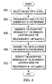
- FIG. 6 is a flow chart showing steps for a method comprising an embodiment of the invention.
- the present invention may be embodied as a system, method or computer program product. Accordingly, the present invention may take the form of an entirely hardware embodiment, an entirely software embodiment (including firmware, resident software, micro-code, etc.) or an embodiment combining software and hardware aspects that may all generally be referred to herein as a “circuit,” “module” or “system.” Furthermore, the present invention may take the form of a computer program product embodied in any tangible medium of expression having computer usable program code embodied in the medium.
- the computer-usable or computer-readable medium may be, for example but not limited to, an electronic, magnetic, optical, electromagnetic, infrared, or semiconductor system, apparatus, device, or propagation medium.
- the computer-readable medium would include the following: an electrical connection having one or more wires, a portable computer diskette, a hard disk, a random access memory (RAM), a read-only memory (ROM), an erasable programmable read-only memory (EPROM or Flash memory), an optical fiber, a portable compact disc read-only memory (CDROM), an optical storage device, a transmission media such as those supporting the Internet or an intranet, or a magnetic storage device.
- a computer-usable or computer-readable medium could even be paper or another suitable medium upon which the program is printed, as the program can be electronically captured, via, for instance, optical scanning of the paper or other medium, then compiled, interpreted, or otherwise processed in a suitable manner, if necessary, and then stored in a computer memory.
- a computer-usable or computer-readable medium may be any medium that can contain, store, communicate, propagate, or transport the program for use by or in connection with the instruction execution system, apparatus, or device.
- the computer-usable medium may include a propagated data signal with the computer-usable program code embodied therewith, either in baseband or as part of a carrier wave.
- the computer usable program code may be transmitted using any appropriate medium, including but not limited to wireless, wireline, optical fiber cable, RF, etc.
- Computer program code for carrying out operations of the present invention may be written in any combination of one or more programming languages, including an object oriented programming language such as Java, Smalltalk, C++ or the like and conventional procedural programming languages, such as the “C” programming language or similar programming languages.
- the program code may execute entirely on the user's computer, partly on the user's computer, as a stand-alone software package, partly on the user's computer and partly on a remote computer or entirely on the remote computer or server.
- the remote computer may be connected to the user's computer through any type of network, including a local area network (LAN) or a wide area network (WAN), or the connection may be made to an external computer (for example, through the Internet using an Internet Service Provider).
- LAN local area network
- WAN wide area network
- Internet Service Provider for example, AT&T, MCI, Sprint, EarthLink, MSN, GTE, etc.
- These computer program instructions may be provided to a processor of a general purpose computer, special purpose computer, or other programmable data processing apparatus to produce a machine, such that the instructions, which execute via the processor of the computer or other programmable data processing apparatus, create means for implementing the functions/acts specified in the flowchart and/or block diagram block or blocks.
- These computer program instructions may also be stored in a computer-readable medium that can direct a computer or other programmable data processing apparatus to function in a particular manner, such that the instructions stored in the computer-readable medium produce an article of manufacture including instruction means which implement the function/act specified in the flowchart and/or block diagram block or blocks.
- the computer program instructions may also be loaded onto a computer or other programmable data processing apparatus to cause a series of operational steps to be performed on the computer or other programmable apparatus to produce a computer implemented process such that the instructions which execute on the computer or other programmable apparatus provide processes for implementing the functions/acts specified in the flowchart and/or block diagram block or blocks.
- Systems network 100 is a network of computers and other components that includes a linking network 102 , the medium used to provide communication links between various devices and computers connected together within systems network 100 .
- Network 102 may include connections, such as wire, wireless communication links, or fiber optic cables.
- server 104 and server 106 connect to network 102 along with a storage unit 108 .
- clients 110 , 112 , and 114 connect to network 102 .
- These clients 110 , 112 , and 114 may be, for example, personal computers or network computers.
- Network data processing system 100 may include additional servers, clients, and other devices not shown.
- network 102 of systems network 100 could be the Internet, including a worldwide collection of networks and gateways that use the Transmission Control Protocol/Internet Protocol (TCP/IP) suite of protocols to communicate with one another.
- TCP/IP Transmission Control Protocol/Internet Protocol
- Data processing system 200 is an example of a computer, such as server 104 , or client 110 or client 112 in FIG. 1 , in which computer usable code or instructions implementing the processes for embodiments of the present invention may be located.
- data processing system 200 employs a hub architecture including north bridge and memory controller hub (NB/MCH) 202 and south bridge and input/output (I/O) controller hub (SB/ICH) 204 .
- NB/MCH north bridge and memory controller hub
- I/O input/output controller hub
- Processing unit 206 , main memory 208 , and graphics processor 210 are connected to NB/MCH 202 .
- Graphics processor 210 may be connected to NB/MCH 202 through an accelerated graphics port (AGP).
- AGP accelerated graphics port
- local area network (LAN) adapter 212 connects to SB/ICH 204 .
- Audio adapter 216 , keyboard and mouse adapter 220 , modem 222 , read only memory (ROM) 224 , hard disk drive (HDD) 226 , CD-ROM drive 230 , universal serial bus (USB) ports and other communication ports 232 , and PCI/PCIe devices 234 connect to SB/ICH 204 through bus 238 and bus 240 .
- PCI/PCIe devices may include, for example, Ethernet adapters, add-in cards, and PC cards for notebook computers. PCI uses a card bus controller, while PCIe does not.
- ROM 224 may be, for example, a flash binary input/output system (BIOS).
- HDD 226 and CD-ROM drive 230 connect to SB/ICH 204 through bus 240 .
- HDD 226 and CD-ROM drive 230 may use, for example, an integrated drive electronics (IDE) or serial advanced technology attachment (SATA) interface.
- IDE integrated drive electronics
- SATA serial advanced technology attachment
- Super I/O (SIO) device 236 may be connected to SB/ICH 204 .
- An operating system runs on processing unit 206 and coordinates and provides control of various components within data processing system 200 in FIG. 2 .
- the operating system may be a commercially available operating system such as Microsoft® Windows® XP (Microsoft and Windows are trademarks of Microsoft Corporation in the United States, other countries, or both).
- An object-oriented programming system such as the JavaTM programming system, may run in conjunction with the operating system and provides calls to the operating system from JavaTM programs or applications executing on data processing system 200 (Java is a trademark of Sun Microsystems, Inc. in the United States, other countries, or both).
- data processing system 200 may be, for example, an IBM® eServerTM pSeries® computer system, running the Advanced Interactive Executive (AIX®) operating system or the LINUX® operating system (eServer, pSeries and AIX are trademarks of International Business Machines Corporation in the United States, other countries, or both while LINUX is a trademark of Linus Torvalds in the United States, other countries, or both).
- Data processing system 200 may be a symmetric multiprocessor (SMP) system including a plurality of processors in processing unit 206 . Alternatively, a single processor system may be employed.
- SMP symmetric multiprocessor
- Instructions for the operating system, the object-oriented programming system, and applications or programs are located on storage devices, such as HDD 226 , and may be loaded into main memory 208 for execution by processing unit 206 .
- the processes for embodiments of the present invention are performed by processing unit 206 using computer usable program code, which may be located in a memory such as, for example, main memory 208 , ROM 224 , or in one or more peripheral devices 226 and 230 .
- main memory 208 e.g., main memory 208 , ROM 224 , or in one or more peripheral devices 226 and 230 .
- a bus system may be comprised of one or more buses, such as bus 238 or bus 240 as shown in FIG. 2 .
- the bus system may be implemented using any type of communication fabric or architecture that provides for a transfer of data between different components or devices attached to the fabric or architecture.
- a communication unit may include one or more devices used to transmit and receive data, such as modem 222 or network adapter 212 of FIG. 2 .
- a memory may be, for example, main memory 208 , ROM 224 , or a cache such as found in NB/MCH 202 in FIG. 2 .
- clients 110 and 112 could be remotely located from one another, and the user of client 110 could seek to send a message to the user of client 112 , where it was necessary to encrypt the message. Accordingly, client 110 could be used to encrypt the message, in accordance with an embodiment of the invention as described hereinafter.
- the encrypted message would be sent or transmitted to client 112 by means of network 102 .
- Client 112 would then be used to decrypt the message, likewise as described hereinafter.
- FIG. 3 there is shown a schematic diagram illustrating simplified components for an embodiment of the invention.
- FIG. 3 more specifically shows a message sender 302 at a first location that is operable to send a message M, following encryption, to a message receiver 304 at a second location.
- Sender 302 could, for example, comprise a client such as client 110 of FIG. 1 , which is used or operated by the sender of the message.
- receiver 304 could comprise a client such as client 112 of FIG. 1 , which is used or operated by the recipient of the message.
- embodiments of the invention are not limited thereto.
- the message M is a number, comprising a positive integer that has a meaning which is known to both the sender at the first location and the recipient at the second location.
- M could represent a letter of the alphabet or other symbol, or could represent other particular information.
- M could also be one element in a succession or string of elements that are sent from sender 302 to receiver 304 , wherein the elements collectively provide information intended for the recipient at the second location, and each element is an encrypted portion of the information.
- a random number P is selected for the sender 302
- a random number Q is selected for the receiver 304
- P and Q are both positive integers.
- P and Q can each be a non-prime number or a prime number, selectively.
- P and Q must both be greater than one, that is, P>1 and Q>1, and the product of P and Q minus one, that is, the quantity (PQ ⁇ 1), must be greater than the message M.
- a random number i must also be selected for the encryption.
- Equation (2) specifies that M is computed to be the remainder that is left after dividing the quantity (EQ i ) by the quantity (PQ ⁇ 1), which serves as a modulus value.
- a table can be constructed at the sender 302 , by computing the quantity [P i mod(PQ ⁇ 1)] for different values of P and i.
- the value of [P i mod(PQ ⁇ 1)] for given values of P and i may then be quickly obtained, just by selection from the table. Such values can be precomputed, during periods when the system is idle.
- such quantity is 5, i.e., 9 divided into 5 is 0, with a remainder of 5.
- At row 404 such quantity is 7, i.e., 9 divided into 25 has a remainder of 7.
- At row 406 such quantity is 9, i.e., 9 divided into 125 has a remainder of 9.
- Equation (1) Equation (1)
- the encrypted message is sent as a tuple (E,i).
- S E the transmission length for the total amount of data required to transmit the encrypted message, is equal to the sum of the length of E and the length of i.
- the length of S E may in fact be substantially less than the length of message M.
- S E can be reduced significantly in embodiments of the invention, by judiciously selecting the particular value of i that is used for the message encryption. By choosing an optimal value of i, a very acceptable tradeoff can be achieved, between the amount of computation involved and the amount of data which is to be transmitted from the sender to the recipient.
- the data transmission length for E and i when i is equal to 1, and also the transmission length when i is equal to 4, is substantially greater than the transmission length when i is equal to 3.
- FIG. 6 there is shown a flow chart depicting basic steps of a method comprising an embodiment of the invention, as described above.
- Values for P, Q and i are respectively selected at step 602 .
- P and Q are both furnished or provided to the sender of message M at the first location, and are also furnished to the recipient at the second location.
- step 608 indicates transmission of the tuple (E,i) from the sender at the first location to the recipient at the second location.
- the decryption task may make use of a precomputed value for Q i mod(PQ ⁇ 1) for the selected i, if such precomputed value is available in a table or the like.
- each block in the flowchart or block diagrams may represent a module, segment, or portion of code, which comprises one or more executable instructions for implementing the specified logical function(s).
- the functions noted in the block may occur out of the order noted in the figures. For example, two blocks shown in succession may, in fact, be executed substantially concurrently, or the blocks may sometimes be executed in the reverse order, depending upon the functionality involved.
- the invention can take the form of an entirely hardware embodiment, an entirely software embodiment or an embodiment containing both hardware and software elements.
- the invention is implemented in software, which includes but is not limited to firmware, resident software, microcode, etc.
- the invention can take the form of a computer program product accessible from a computer-usable or computer-readable medium providing program code for use by or in connection with a computer or any instruction execution system.
- a computer-usable or computer readable medium can be any tangible apparatus that can contain, store, communicate, propagate, or transport the program for use by or in connection with the instruction execution system, apparatus, or device.
- the medium can be an electronic, magnetic, optical, electromagnetic, infrared, or semiconductor system (or apparatus or device) or a propagation medium.
- Examples of a computer-readable medium include a semiconductor or solid state memory, magnetic tape, a removable computer diskette, a random access memory (RAM), a read-only memory (ROM), a rigid magnetic disk and an optical disk.
- Current examples of optical disks include compact disk-read only memory (CD-ROM), compact disk-read/write (CD-R/W) and DVD.
- a data processing system suitable for storing and/or executing program code will include at least one processor coupled directly or indirectly to memory elements through a system bus.
- the memory elements can include local memory employed during actual execution of the program code, bulk storage, and cache memories which provide temporary storage of at least some program code in order to reduce the number of times code must be retrieved from bulk storage during execution.
- I/O devices including but not limited to keyboards, displays, pointing devices, etc.
- I/O controllers can be coupled to the system either directly or through intervening I/O controllers.
- Network adapters may also be coupled to the system to enable the data processing system to become coupled to other data processing systems or remote printers or storage devices through intervening private or public networks.
- Modems, cable modem and Ethernet cards are just a few of the currently available types of network adapters.
Abstract
Description
E=(MP i)mod(PQ−1) Equation (1)
M=(EQ i)mod(PQ−1) Equation (2)
E=(MP i)mod(PQ−1)={M*[P i mod(PQ−1)]} mod(PQ−1).
In view of this equivalence, a table can be constructed at the
E=M[P i mod(PQ−1)] mod(PQ−1)]=3*7
Claims (17)
Priority Applications (1)
| Application Number | Priority Date | Filing Date | Title |
|---|---|---|---|
| US12/887,012 US8615649B2 (en) | 2010-09-21 | 2010-09-21 | Use of a private key to encrypt and decrypt a message |
Applications Claiming Priority (1)
| Application Number | Priority Date | Filing Date | Title |
|---|---|---|---|
| US12/887,012 US8615649B2 (en) | 2010-09-21 | 2010-09-21 | Use of a private key to encrypt and decrypt a message |
Publications (2)
| Publication Number | Publication Date |
|---|---|
| US20120070003A1 US20120070003A1 (en) | 2012-03-22 |
| US8615649B2 true US8615649B2 (en) | 2013-12-24 |
Family
ID=45817787
Family Applications (1)
| Application Number | Title | Priority Date | Filing Date |
|---|---|---|---|
| US12/887,012 Active 2032-02-24 US8615649B2 (en) | 2010-09-21 | 2010-09-21 | Use of a private key to encrypt and decrypt a message |
Country Status (1)
| Country | Link |
|---|---|
| US (1) | US8615649B2 (en) |
Citations (13)
| Publication number | Priority date | Publication date | Assignee | Title |
|---|---|---|---|---|
| US4405829A (en) * | 1977-12-14 | 1983-09-20 | Massachusetts Institute Of Technology | Cryptographic communications system and method |
| US5727062A (en) | 1995-07-06 | 1998-03-10 | Ritter; Terry F. | Variable size block ciphers |
| US20020041683A1 (en) | 2000-09-29 | 2002-04-11 | Hopkins Dale W. | Method for selecting optimal number of prime factors of a modulus for use in a cryptographic system |
| US6499104B1 (en) * | 1997-12-18 | 2002-12-24 | Etat Francais Represente Par Le Delegue General Pour L'armement | Digital signature method |
| US20040078407A1 (en) * | 2002-10-17 | 2004-04-22 | Mats Naslund | Efficient arithmetic in finite fields of odd characteristic on binary hardware |
| US20050031120A1 (en) * | 1999-02-01 | 2005-02-10 | Gideon Samid | Denial featured cryptography |
| US20050086196A1 (en) | 2003-07-16 | 2005-04-21 | Pkware, Inc. | Method and system for decrypting strongly encrypted .ZIP files |
| US7027598B1 (en) | 2001-09-19 | 2006-04-11 | Cisco Technology, Inc. | Residue number system based pre-computation and dual-pass arithmetic modular operation approach to implement encryption protocols efficiently in electronic integrated circuits |
| US20060159259A1 (en) | 2003-10-31 | 2006-07-20 | Gentry Craig B | Encryption and signature schemes using message mappings to reduce the message size |
| US20060210066A1 (en) * | 2003-07-31 | 2006-09-21 | Gemplus | Method for the secure application of a cryptographic algorithm of the rsa type and a corresponding component |
| US7184547B1 (en) * | 1999-01-27 | 2007-02-27 | France Telecom | Authenticating or signature method with reduced computations |
| US7512230B2 (en) | 2002-04-30 | 2009-03-31 | She Alfred C | Method and apparatus of fast modular reduction |
| US20090103726A1 (en) | 2007-10-18 | 2009-04-23 | Nabeel Ahmed | Dual-mode variable key length cryptography system |
-
2010
- 2010-09-21 US US12/887,012 patent/US8615649B2/en active Active
Patent Citations (13)
| Publication number | Priority date | Publication date | Assignee | Title |
|---|---|---|---|---|
| US4405829A (en) * | 1977-12-14 | 1983-09-20 | Massachusetts Institute Of Technology | Cryptographic communications system and method |
| US5727062A (en) | 1995-07-06 | 1998-03-10 | Ritter; Terry F. | Variable size block ciphers |
| US6499104B1 (en) * | 1997-12-18 | 2002-12-24 | Etat Francais Represente Par Le Delegue General Pour L'armement | Digital signature method |
| US7184547B1 (en) * | 1999-01-27 | 2007-02-27 | France Telecom | Authenticating or signature method with reduced computations |
| US20050031120A1 (en) * | 1999-02-01 | 2005-02-10 | Gideon Samid | Denial featured cryptography |
| US20020041683A1 (en) | 2000-09-29 | 2002-04-11 | Hopkins Dale W. | Method for selecting optimal number of prime factors of a modulus for use in a cryptographic system |
| US7027598B1 (en) | 2001-09-19 | 2006-04-11 | Cisco Technology, Inc. | Residue number system based pre-computation and dual-pass arithmetic modular operation approach to implement encryption protocols efficiently in electronic integrated circuits |
| US7512230B2 (en) | 2002-04-30 | 2009-03-31 | She Alfred C | Method and apparatus of fast modular reduction |
| US20040078407A1 (en) * | 2002-10-17 | 2004-04-22 | Mats Naslund | Efficient arithmetic in finite fields of odd characteristic on binary hardware |
| US20050086196A1 (en) | 2003-07-16 | 2005-04-21 | Pkware, Inc. | Method and system for decrypting strongly encrypted .ZIP files |
| US20060210066A1 (en) * | 2003-07-31 | 2006-09-21 | Gemplus | Method for the secure application of a cryptographic algorithm of the rsa type and a corresponding component |
| US20060159259A1 (en) | 2003-10-31 | 2006-07-20 | Gentry Craig B | Encryption and signature schemes using message mappings to reduce the message size |
| US20090103726A1 (en) | 2007-10-18 | 2009-04-23 | Nabeel Ahmed | Dual-mode variable key length cryptography system |
Non-Patent Citations (5)
| Title |
|---|
| Chandrasekaran et al.. A novel asymmetric keyless algorithm. Nov. 14, 2009. * |
| Jablon. Strong password-only authenticated key exchange. Sigcomm. Sep. 25, 1996. * |
| Mirvaziri et al., "Message Based Random Variable Length Key Encryption Algorithm", Journal of Computer Science 5 (8) 2009, pp. 573-578. |
| Sobe et al., "Combining Compression, Encryption and Fault-tolerant Coding for Distributed Storage", 2007, IEEE, pp. 1-8. |
| Winton. Enhancing the Massey-Omura Cryptosystem. 2007. * |
Also Published As
| Publication number | Publication date |
|---|---|
| US20120070003A1 (en) | 2012-03-22 |
Similar Documents
| Publication | Publication Date | Title |
|---|---|---|
| RU2691874C2 (en) | Method of protecting information in cloud computing using homomorphic encryption | |
| US10608811B2 (en) | Private set intersection encryption techniques | |
| US8751789B2 (en) | General purpose distributed encrypted file system | |
| JP6880017B2 (en) | Systems and processes for running private programs on untrusted computers | |
| US10255450B2 (en) | Customer load of field programmable gate arrays | |
| US8958548B2 (en) | Generation of relative prime numbers for use in cryptography | |
| US20120269340A1 (en) | Hierarchical encryption/decryption device and method thereof | |
| JP2008109662A (en) | Systems and method for management and auto-generation of encryption key and computer program product | |
| US10608813B1 (en) | Layered encryption for long-lived data | |
| AU2019448601B2 (en) | Privacy preserving oracle | |
| JP6730740B2 (en) | Processing device, processing method, processing program, and cryptographic processing system | |
| JP2007233381A (en) | Graphics processing unit used for cryptographic processing | |
| US10476663B1 (en) | Layered encryption of short-lived data | |
| WO2021129470A1 (en) | Polynomial-based system and method for fully homomorphic encryption of binary data | |
| JP2023063430A (en) | Encryption system, key generation apparatus, encryption apparatus, decryption apparatus, method, and program | |
| US11356254B1 (en) | Encryption using indexed data from large data pads | |
| US10333699B1 (en) | Generating a pseudorandom number based on a portion of shares used in a cryptographic operation | |
| US8615649B2 (en) | Use of a private key to encrypt and decrypt a message | |
| EP4072062A1 (en) | Apparatus for processing non-polynomial operation on homomorphic encrypted messages and methods thereof | |
| US8731187B2 (en) | Computing genus-2 curves using general isogenies | |
| JP7212179B2 (en) | Compression and forgetful expansion of RLWE ciphertext | |
| JP2008286964A (en) | Encryption apparatus, decryption apparatus, encryption method, decryption method and program for stream encryption | |
| KR101462335B1 (en) | Method for efficient data sharing in hierarchical storage and apparatus for processing the same method | |
| Attri et al. | Enhancing Cloud Security Using Secured Binary-DNA Approach with Impingement Resolution and Complex Key Generation | |
| JP2018025587A (en) | Secret computation technique and method of the same |
Legal Events
| Date | Code | Title | Description |
|---|---|---|---|
| AS | Assignment |
Owner name: INTERNATIONAL BUSINESS MACHINES CORPORATION, NEW Y Free format text: ASSIGNMENT OF ASSIGNORS INTEREST;ASSIGNORS:CHANDRASEKARAN, SUBRAMANIYAM;RAMACHANDRAN, ARUN C.;VELUSAMY, LAKSHMANAN;AND OTHERS;REEL/FRAME:025022/0717 Effective date: 20100920 |
|
| STCF | Information on status: patent grant |
Free format text: PATENTED CASE |
|
| AS | Assignment |
Owner name: LENOVO INTERNATIONAL LIMITED, HONG KONG Free format text: ASSIGNMENT OF ASSIGNORS INTEREST;ASSIGNOR:INTERNATIONAL BUSINESS MACHINES CORPORATION;REEL/FRAME:034194/0291 Effective date: 20140926 |
|
| FPAY | Fee payment |
Year of fee payment: 4 |
|
| MAFP | Maintenance fee payment |
Free format text: PAYMENT OF MAINTENANCE FEE, 8TH YEAR, LARGE ENTITY (ORIGINAL EVENT CODE: M1552); ENTITY STATUS OF PATENT OWNER: LARGE ENTITY Year of fee payment: 8 |