US8619071B2 - Image view synthesis using a three-dimensional reference model - Google Patents
Image view synthesis using a three-dimensional reference model Download PDFInfo
- Publication number
- US8619071B2 US8619071B2 US12/211,596 US21159608A US8619071B2 US 8619071 B2 US8619071 B2 US 8619071B2 US 21159608 A US21159608 A US 21159608A US 8619071 B2 US8619071 B2 US 8619071B2
- Authority
- US
- United States
- Prior art keywords
- image
- block
- destination
- reference model
- depth
- Prior art date
- Legal status (The legal status is an assumption and is not a legal conclusion. Google has not performed a legal analysis and makes no representation as to the accuracy of the status listed.)
- Expired - Fee Related, expires
Links
Images


Classifications
-
- G—PHYSICS
- G06—COMPUTING; CALCULATING OR COUNTING
- G06T—IMAGE DATA PROCESSING OR GENERATION, IN GENERAL
- G06T15/00—3D [Three Dimensional] image rendering
- G06T15/10—Geometric effects
- G06T15/20—Perspective computation
Definitions
- a novel image view may be synthesized using a three-dimensional reference model.
- a device-implemented method for synthesizing a novel image view includes acts of registering, selecting, applying and synthesizing.
- An image is registered to at least one reference model.
- a source block of visual data from the image is selected with regard to a destination block of the reference model based on a source depth associated with the source block and a destination depth associated with the destination block.
- the destination position of the destination block of the reference model is not visible in the image.
- the source block of visual data from the image is applied to the destination block of the reference model to produce an image-augmented model.
- a novel image view is synthesized using the image-augmented model.
- FIG. 1 illustrates an example of a general approach to producing a modified image with an image view synthesis operation using an image manipulator and based on a reference model.
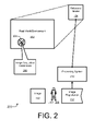
- FIG. 2 illustrates an example of a general scheme for registering an image with a reference model.
- FIG. 3 is a flow diagram that illustrates an example of a method for manipulating an image to synthesize a novel view based on a reference model.
- FIGS. 4A and 4B are block diagrams illustrating examples of how image views may be changed.
- FIG. 5 is a block diagram illustrating an example selection of a source block from an image for application to a destination block of a reference model to produce an image-augmented model.
- FIG. 6 is a block diagram of an example image manipulator that enhances an image by producing a modified image having a novel image view using a reference model and an image view synthesizer.
- FIG. 7 is a block diagram illustrating example devices that may be used to implement embodiments for image view synthesis using a three-dimensional reference model.
- An image manipulation system that involves geo-registering is motivated by several recent trends that are now reaching critical mass.
- One trend is that of geo-tagged photos.
- Many photo-sharing web sites now enable users to manually add location information to photos.
- Some digital cameras feature a built-in GPS, allowing automatic location tagging.
- a number of manufacturers offer small GPS units that allow photos to be easily geo-tagged by software that synchronizes the GPS log with the photos.
- location tags can be enhanced by digital compasses that are able to measure the orientation (e.g., tilt and heading) of the camera. It is expected that in the future more cameras will have such functionality and that most photographic images will be geo-tagged, even without manual efforts.
- Embodiments may employ a model-guided, layered depth image completion technique for novel view synthesis.
- the novel image view synthesis may entail, by way of example but not limitation: adding material to a background to extend it, changing a direction of view for the image, moving a capture camera position to move the view frustum, effectively adding background objects through image expansion or view direction change, combinations thereof, and so forth.
- example system embodiments are described for enhancing and otherwise manipulating outdoor photographic images by “combining” them with already-existing, geo-referenced digital terrain and urban reference models.
- An interactive registration process may be used to align an image with such a reference model. After the image and the model have been registered, an abundance of information becomes available to the system. Examples of available information include depth, texture, color, GIS data, combinations thereof, and so forth.
- This information enables a variety of operations, ranging from dehazing and relighting of the image, to novel view synthesis and overlaying of the image with geographic information.
- Augmenting photographic images with already-available 3D models of the world can support a wide variety of new ways for people to experience and interact with everyday snapshots. The description that follows focuses on example approaches to synthesizing novel image views.
- FIG. 1 illustrates an example of a general approach 100 to producing a modified image 108 with an image view synthesis operation 110 using an image manipulator 106 and based on a reference model 104 .
- approach 100 includes an image 102 , reference model 104 , image manipulator 106 , modified image 108 , and image view synthesis operation 110 .
- Image 102 may be, for example, any digital two-dimensional image, such as those taken by digital or traditional-film cameras.
- Reference model 104 provides one or more 3D models of the real-world. Examples of reference models 104 are described further herein below with particular reference to FIG. 2 .
- image 102 and reference model 104 are provided to image manipulator 106 .
- Image 102 is registered in conjunction with reference model 104 .
- Image manipulator 106 performs an image view synthesis operation 110 to produce modified image 108 .
- Modified image 108 is a view-adjusted version of image 102 .
- the view may be adjusted by extending the image, altering the viewpoint (e.g., changing the view direction and/or changing the location of the viewing frustum), effectively adding background objects, combinations thereof, and so forth.
- image view synthesis operation 110 entails adjusting the view of image 102 based on depths of blocks in image 102 and depths of blocks of reference model 104 .
- Image manipulator 106 may be realized as software, firmware, hardware, fixed logic circuitry, some combination thereof, and so forth.
- FIG. 2 illustrates an example of a general scheme 200 for registering image 102 with reference model 104 .
- scheme 200 includes a real-world environment 202 , a camera (or capture) position 204 , image acquisition parameters 206 , and a user 208 .
- Scheme 200 also includes a processing system 210 and an image registration 212 in addition to image 102 and reference model 104 .
- reference model 104 generally corresponds to real-world environment 202 . More specifically, but by way of example only, respective individual locations, points, and visible subject matter of real-world environment 202 correspond to respective 3D maps, pixels, and textures of reference model 104 .
- Processing system 210 includes or otherwise has access to reference model 104 .
- Processing system 210 may be a discrete device or a distributed set of two or more devices interconnected by a network and formed from software, firmware, hardware, fixed logic circuitry, some combination thereof, and so forth.
- Processing system 210 may include image manipulator 106 (of FIG. 1 ).
- Reference models 104 may be created or acquired from any of many possible sources. For example, due to commercial projects that attempt to reproduce the Earth visually on the web, both the quantity and the quality of such models are rapidly increasing. In the public domain, NASA for instance provides detailed satellite imagery (e.g., from Landsat) and elevation models (e.g., from Shuttle Radar Topography Mission). Also, a number of cities around the world are creating detailed 3D models of their cityscape (e.g., New York, Berlin 3D, etc.).
- a user 208 captures image 102 in real-world environment 202 at camera position 204 .
- image acquisition parameters 206 Associated with this camera position 204 and the act of capturing image 102 are image acquisition parameters 206 .
- user 208 performs image registration 212 to register image 102 in conjunction with one or more reference models 104 .
- image acquisition parameters 206 are used to link image 102 to the data in reference model 104 .
- the registration process may be fully or partially manual or automatic.
- image acquisition parameters 206 may include position, pose, and focal length (e.g., seven parameters in total). To register such an image to a 3D geometric model of a scene, it suffices to specify four or more corresponding pairs of points.
- camera position 204 may be specified for image registration 212 with a location (e.g., spatially in three dimensions) and three angles of the camera (e.g., two directional angles and one field of view angle).
- the model may be rendered from roughly the correct position. If the user specifies sufficiently numerous correspondences between the image and the reference model, the parameters may be recovered by solving a nonlinear system of equations.
- reference models are less likely to include models of foreground objects that are dynamic or less permanent, such as people, cars, and even individual trees.
- the user may matte out the foreground before combining the remainder of the image with the reference model.
- the matte does not need to be overly accurate, especially if it is conservative (e.g., substantially all of the foreground pixels are contained in the matte).
- the matting process can typically be completed in about 1-2 minutes per image. So, for some images, the user first spends some time on interactive matting prior to image manipulation. It should be noted that as a consequence of the matting, the fidelity of some of the image manipulations with regard to the foreground may be reduced. After the image manipulations, the matted foreground may be composited back into the overall photographic image.
- FIG. 3 is a flow diagram 300 that illustrates an example of a method for manipulating an image to synthesize a novel view based on a reference model.
- Flow diagram 300 includes eight blocks 302 - 310 , 308 ( 1 ), 308 ( 2 ), and 308 ( 3 ). Implementations of flow diagram 300 may be realized, for example, as processor-executable instructions and/or as part of image manipulator 106 (of FIG. 1 ) or processing system 210 (of FIG. 2 ).
- Example relatively quantitative embodiments for implementing flow diagram 300 are described below using the concepts, terminology, and elements of FIGS. 4A , 4 B, and 5 .
- flow diagram 300 may be performed in many different environments and with a variety of different devices, such as by one or more processing devices (e.g., of FIG. 7 ).
- the order in which the method is described is not intended to be construed as a limitation, and any number of the described blocks can be combined, augmented, rearranged, and/or omitted to implement a respective method, or an alternative method that is equivalent thereto.
- FIGS. e.g., FIGS. 1 and 2
- the method may be performed with alternative elements.
- an image is received.
- user 208 may store, input, upload, or otherwise provide image 102 .
- the image is registered to a reference model.
- user 208 may register image 102 in conjunction with one or more reference models 104 using processing system 210 .
- an image manipulation operation request is received.
- processing system 210 and/or image manipulator 106 may receive a request to perform an image view synthesis operation 110 .
- the request may be submitted by user 208 upon providing image 102 , may be selected by user 208 from among a set of image manipulation options, and so forth.
- the image is manipulated based on the reference model and responsive to the requested manipulation operation.
- image 102 may be manipulated with image manipulator 106 by performing image view synthesis operation 110 on image 102 based on reference model 104 .
- a source block of visual data is selected from the image with regard to a targeted destination block of the reference model based on one or more criteria.
- the criteria may be, for example, a source depth of the source block and a destination depth of the destination block.
- Other criteria may include, for instance, corresponding spatial positions, similarities of color, proximity to previously selected blocks, and so forth.
- the source block of visual data is applied to the destination block of the reference model to produce an image-augmented model.
- a texture of the destination block of reference model 104 may be replaced with or modified responsive to the visual data of the source block from image 102 .
- the destination position of the destination block of the reference model may be such that it is not visible in the image.
- a novel image view is synthesized using the image-augmented model.
- a modified image 108 including a novel view may be synthesized using the image-augmented model.
- modified image 108 which includes a synthesized novel view of image 102 , may be output.
- Modified image 108 may be, for instance, stored to memory, transmitted over one or more networks (e.g., back to user 208 ), displayed on a screen, printed on paper, some combination thereof, and so forth.
- FIGS. 4A and 4B are block diagrams 400 A and 400 B illustrating examples of how image views may be changed. Both diagrams depict a scenic vista having three mountains and a hilly horizon. The three mountains are represented by three triangles and the hilly horizon is represented by a wavy line. These scenic aspects are not numbered for the sake of clarity. In the figures, the scenic aspects simultaneously represent real-world and reference model aspects. It should be noted that the scenic aspects and explanatory elements are not necessarily drawn to scale. Also, it should be understood that the three-dimensional world as well as the illustrated image view elements may not be ideally presented in the two-dimensional figures.
- an image 102 is captured from camera position 204 .
- the current view angle and position are indicated by view frustum 402 (delineated by long dashed lines).
- Image 102 includes visual data 404 , such as mountains, fields, buildings, and so forth. These mountains, fields, buildings, etc. are also modeled within reference model 104 .
- visual data 404 from image 102 may be applied to reference model 104 to produce an image-augmented model.
- augmented portions 406 are identified in block diagram 400 A. As shown, augmented portions 406 extend the image leftward and rightward into regions (delineated by the short dashed lines) of reference model 104 that are not visible in image 102 . The extended image 102 is output as modified image 108 .
- the view frustum has been changed such that the view point and perspective between a source image and a modified image 108 is changed.
- the original source camera position 204 is shown; however, the original source view frustum 402 , which is shown in FIG. 4A , is omitted for the sake of clarity in FIG. 4B . Instead, an adjusted view frustum 402 * is shown (as delineated by short dashed lines).
- both the directional view angle and the location/position of the view frustum have been changed for the novel image view. It should be noted that one or the other may also be changed.
- Augmented portion 406 a may also correspond to regions that were occluded from view in original image 102 .
- areas blocked from the view of the camera by the smaller mountain on the left may be hallucinated using described implementations to produce modified image 108 .
- FIG. 5 is a block diagram 500 illustrating an example selection of a source block 502 from an image 102 for application to a destination block 504 of a reference model 104 to produce an image-augmented model.
- block diagram 500 includes image 102 , reference model 104 , modified image 108 , camera position 204 , view frustum 402 , and augmented portion 406 .
- Block diagram 500 also includes source blocks 502 , destination block 504 , and depths 506 . Specifically, a source depth 506 S and a destination depth 506 D are shown.
- reference model 104 is augmented by applying source blocks 502 to destination blocks 504 .
- a source block 502 is selected for application thereto.
- each source block 502 includes visual data from image 102
- each destination block 504 includes a texture from reference model 104 .
- Each block 502 or 504 may be a pixel or a set of pixels of any size or shape.
- each block 502 or 504 may be a patch of a fixed or variable size. Blocks 502 and 504 may be otherwise defined.
- the selection of a source block 502 for application to a destination block 504 may be based on one or more criteria, such as the depths 506 of the blocks 502 and 504 .
- Each depth 506 may correspond to a distance between camera position 204 and a block 502 or 504 .
- each respective source block 502 is associated with a respective source depth 506 S.
- each respective destination block 504 is associated with a respective destination depth 506 D.
- proximate blocks As shown in block diagram 500 , three source blocks 502 ( 1 ), 502 ( 2 ), and 502 ( 3 ) are considered for application to destination block 504 . However, any number of source blocks 502 may be considered for each destination block 504 . Additionally, other selection criteria may be used. Example other selection criteria include, but are not limited to, relative block positions, color correspondences, keeping proximate blocks together to maintain visual consistency, and so forth. With regard to proximate blocks, the source block of visual data from the image may be selected with regard to the destination block of the reference model responsive to a bias towards selecting proximate source blocks for proximate destination blocks to provide visual consistency to the proximate destination blocks. In this sense, proximate blocks may be considered, for example, those that form a visual element that is identifiable by the human eye.
- a given processing system 210 may operate in any of a number of different manners.
- an appreciable part of reference model 104 may first be retextured using source blocks 502 from image 102 to create augmented portions 406 and ultimately produce an image-augmented model.
- a user may change the perspective (e.g., directional angle and/or location) of view frustum 402 to reveal what a modified image 108 would look like.
- the user may first change the perspective of view frustum 402 and then be presented an interim image having portions of the scene that include the modeled texture of reference model 104 .
- the newly visible portions may be textured by applying source blocks 502 to destination blocks 504 .
- Other operational manners may alternatively be implemented.
- FIG. 6 is a block diagram 600 of an example image manipulator 106 that enhances an image 102 by producing a modified image 108 having a novel image view using a reference model 104 and an image view synthesizer 608 .
- image manipulator 106 includes an image registration unit 602 , a source block selector 604 , a visual image data application unit 606 , and image view synthesizer 608 .
- Image manipulator 106 operates with and/or produces source blocks 502 , destination blocks 504 , and an image-augmented model 610 .
- Image-augmented model 610 is formed from reference model 104 with one or more augmented portions 406 (of FIGS. 4A , 4 B, and 4 C).
- Image 102 and reference model 104 are input to image manipulator 106 .
- Image manipulator 106 outputs modified image 108 .
- image manipulator 106 includes an image registration unit 602 , a source block selector 604 , a visual image data application unit 606 , and an image view synthesizer 608 .
- Image registration unit 602 registers image 102 to at least one reference model 104 .
- Source block selector 604 selects a source block 502 having visual data from image 102 with regard to a destination block 504 of reference model 104 based on a source depth associated with source block 502 and a destination depth associated with destination block 504 .
- a position of destination block 504 of reference model 104 need not be visible in image 102 .
- Visual image data application unit 606 applies the visual data of source block 502 from image 102 to destination block 504 of reference model 104 to produce an image-augmented model 610 .
- Image view synthesizer 608 synthesizes a novel image view using image-augmented model 610 .
- Novel view synthesis can provide the ability to modify the viewpoint from which an original photograph was taken or otherwise change the original view frustum. Effectively bringing static photographic images to life in such a manner can significantly enhance the photo browsing experience.
- a challenge in changing the viewpoint involves completing the missing texture in areas that are either occluded or are merely outside the original view frustum.
- image completion is used to “fill” the missing areas with texture from the photographic image.
- the image completion process is analogous to paint or “texture”-by-numbers.
- a guidance map is used to derive the textures for portions of the 3D reference model that are to be augmented.
- reference models are typically aerial images of the terrain.
- reference models usually include texture maps of the buildings.
- the texture is synthesized over a cylindrical layered depth image (LDI), which is centered on the original camera position.
- the LDI stores, for each pixel, the depths and normals of scene points intersected by the corresponding ray from the viewpoint. This data structure is able to represent both the visible and the occluded parts of the scene.
- the colors of the front-most layer for each pixel are taken from the original image if they are inside the original view frustum. The remaining colors are synthesized using a guided texture transfer, as described herein.
- a different number of layers for the LDI may be used, an example number of depth layers per pixel is four. It should be noted that although the relatively quantitative description herein refers to a source or destination block 502 or 504 as having a size of one pixel, the principles are also applicable to different block sizes and shapes.
- the texture transfer process is started by computing guiding values for layers of the LDI at each pixel.
- the guiding value is a vector (U, V, D), where U and V are the chrominance values of the corresponding point in the model texture, and D is the distance or depth to the corresponding scene point from the location of the camera.
- U and V are the chrominance values of the corresponding point in the model texture
- D is the distance or depth to the corresponding scene point from the location of the camera.
- an example depth range is from 0 to 5000 meters, which may be normalized to a [0, 1] interval.
- Texture synthesis may be implemented in a multi-resolution manner.
- the first (and coarsest) level is synthesized by growing the texture outwards from the known regions. For each unknown destination pixel, a square neighborhood around it is examined. An exhaustive search may be conducted for a matching neighborhood source from the known regions of the image. By way of example only, an L 2 norm criterion may be used to determine a degree of matching.
- the first level is sufficiently coarse, so its synthesis can be relatively fast.
- the result of the previous level may be upsampled and a relatively small number of k-coherence synthesis passes are performed to refine the result.
- An example approach to implementing a k-coherence scheme is as follows. First, for each pixel's neighborhood in the source image, the k closest neighborhoods within the same image are found. Second, when synthesizing a targeted image, the location of each target pixel in the source image is stored (e.g., the location from where it is copied). Third, when searching a closest neighborhood for a given target pixel, instead of considering all possible neighborhoods, the k closest neighborhoods of the pixels surrounding the target pixel may be considered. As a result, merely k ⁇ 5 ⁇ 5 neighborhoods are to be considered if 5 ⁇ 5 is the neighborhood size. This can achieve a significant speedup.
- the concept of a pixel's neighborhood is adjusted to account for the existence of multiple depth layers at each pixel.
- the neighborhood of a pixel may be defined as follows: On each depth layer, a pixel has up to 8 pixels surrounding it. If the would-be neighboring pixel has multiple depth layers, the pixel on the layer with the closest depth value is assigned as the “immediate” or actual neighbor.
- other neighborhood definitions may alternatively be implemented, such as some form of averaging, interpolation, and so forth.
- a shader is used to project the LDI image onto the reference model by computing the distance of the model to the camera position and then using the pixel color from the depth layer closest to this distance.
- significant changes in the viewpoint eventually cause texture distortions, if source texture from the image alone is continually applied to destination areas of the model.
- the visual data from the image may be blended with the texture of the reference model as the new virtual camera is moved farther away from the original viewpoint.
- This blending can increase the aesthetic appearance of the 3D viewing experience, often even for drastic view changes, such as switching to a bird's eye view.
- a proportional amount of the visual data of the source block from the image that is applied to the destination block of the reference model may be decreased as a novel perspective viewpoint corresponding to the novel image view deviates further from a capture perspective viewpoint corresponding to the image.
- This blending may be implemented as part of the application of the source blocks to the destination blocks and/or as part of the synthesis of the novel image view.
- the blending factor may be determined according to the following principles: (i) pixels in the original photograph that correspond to surfaces facing the camera are considered more reliable than those on oblique surfaces; and (ii) pixels in the original photograph are desirable whenever the corresponding scene point is viewed from the same direction in the current new view as the scene point was in the original view.
- the blending factor may be determined according to different principles.
- n(x) denotes the surface normal
- C 0 denotes the original camera position from which the photograph was taken
- C new denotes the current camera position
- v 0 (C 0 ⁇ x)/ ⁇ C 0 ⁇ x ⁇ denotes the normalized vector from the scene point to the original camera position
- v new (C new ⁇ x)/ ⁇ C new ⁇ x ⁇ .
- Equation (2) the blending factor g(x) is defined by Equation (2) as the greater between (i) the cosine of the angle between the normal and the original view direction and (ii) the cosine of the angle between the two view directions.
- the depth of objects in the modified image may differ from those of the original image or the objects may be new to the modified image.
- haze affects images based at least partially on the distance between the camera and the objects of the image
- haze may be added and/or adjusted when producing the modified image from the image with a novel image view synthesis. Dehazing and re-hazing may be performed on-the-fly. For example, haze may first be removed from the image. After the novel image view has been synthesized, haze may be added back into the image based on the depth of objects. This re-hazing for the modified image uses the current distances from the current camera position to the various objects.
- FIG. 7 is a block diagram 700 illustrating example devices 702 that may be used to implement embodiments for image view synthesis using a three-dimensional reference model.
- block diagram 700 includes two devices 702 a and 702 b , person-device interface equipment 712 , and one or more network(s) 714 .
- each device 702 may include one or more input/output interfaces 704 , at least one processor 706 , and one or more media 708 .
- Media 708 may include processor-executable instructions 710 .
- device 702 may represent any processing-capable device.
- Example devices 702 include personal or server computers, workstations, hand-held or other portable electronics, entertainment appliances, network components, some combination thereof, and so forth.
- Device 702 a and device 702 b may communicate over network(s) 714 .
- Network(s) 714 may be, by way of example but not limitation, an internet, an intranet, an Ethernet, a public network, a private network, a cable network, a digital subscriber line (DSL) network, a telephone network, a wireless network, some combination thereof, and so forth.
- Image submission and manipulation may both be performed at one device 702 .
- a user may submit an image at one device 702 a , and the image manipulation may occur at another device 702 b .
- reference models may be located at the same or a different device 702 (e.g., that is likewise accessible over network 714 ).
- Person-device interface equipment 712 may be a keyboard/keypad, a touch screen, a remote, a mouse or other graphical pointing device, a display screen, a speaker, and so forth. Person-device interface equipment 712 may be integrated with or separate from device 702 a.
- I/O interfaces 704 may include (i) a network interface for monitoring and/or communicating across network 714 , (ii) a display device interface for displaying information on a display screen, (iii) one or more person-device interfaces, and so forth.
- network interfaces include a network card, a modem, one or more ports, a network communications stack, a radio, and so forth.
- display device interfaces include a graphics driver, a graphics card, a hardware or software driver for a screen or monitor, and so forth.
- Examples of (iii) person-device interfaces include those that communicate by wire or wirelessly to person-device interface equipment 712 .
- a given interface may function as both a display device interface and a person-device interface.
- Processor 706 may be implemented using any applicable processing-capable technology, and one may be realized as a general-purpose or a special-purpose processor. Examples include a central processing unit (CPU), a microprocessor, a controller, a graphics processing unit (GPU), a derivative or combination thereof, and so forth.
- Media 708 may be any available media that is included as part of and/or is accessible by device 702 . It includes volatile and non-volatile media, removable and non-removable media, storage and transmission media (e.g., wireless or wired communication channels), hard-coded logic media, combinations thereof, and so forth. Media 708 is tangible media when it is embodied as a manufacture and/or as a composition of matter.
- processor 706 is capable of executing, performing, and/or otherwise effectuating processor-executable instructions, such as processor-executable instructions 710 .
- Media 708 is comprised of one or more processor-accessible media. In other words, media 708 may include processor-executable instructions 710 that are executable by processor 706 to effectuate the performance of functions by device 702 .
- Processor-executable instructions 710 may be embodied as software, firmware, hardware, fixed logic circuitry, some combination thereof, and so forth.
- processor-executable instructions may include routines, programs, applications, coding, modules, protocols, objects, components, metadata and definitions thereof, data structures, APIs, etc. that perform and/or enable particular tasks and/or implement particular abstract data types.
- Processor-executable instructions may be located in separate storage media, executed by different processors, and/or propagated over or extant on various transmission media.
- media 708 comprises at least processor-executable instructions 710 .
- Processor-executable instructions 710 may comprise, for example, image manipulator 106 (of FIGS. 1 and 6 ) and/or processing system 210 (of FIG. 2 ).
- processor-executable instructions 710 when executed by processor 706 , enable device 702 to perform the various functions described herein.
- Such functions include, by way of example but not limitation, those that are illustrated in flow diagram 300 (of FIG. 3 ) and those pertaining to features illustrated in the various block diagrams, as well as combinations thereof, and so forth.
- FIGS. 1-7 The devices, acts, features, functions, methods, modules, data structures, techniques, components, etc. of FIGS. 1-7 are illustrated in diagrams that are divided into multiple blocks and other elements. However, the order, interconnections, interrelationships, layout, etc. in which FIGS. 1-7 are described and/or shown are not intended to be construed as a limitation, and any number of the blocks and/or other elements can be modified, combined, rearranged, augmented, omitted, etc. in many manners to implement one or more systems, methods, devices, media, apparatuses, arrangements, etc. for image view synthesis using a three-dimensional reference model.
Abstract
Description
T(x)=g(x) T photo(x)+(1−g(x))T model(x), (1)
where the blending factor g(x) is determined with respect to the current view. By way of example, the blending factor may be determined according to the following principles: (i) pixels in the original photograph that correspond to surfaces facing the camera are considered more reliable than those on oblique surfaces; and (ii) pixels in the original photograph are desirable whenever the corresponding scene point is viewed from the same direction in the current new view as the scene point was in the original view. However, the blending factor may be determined according to different principles.
In other words, the blending factor g(x) is defined by Equation (2) as the greater between (i) the cosine of the angle between the normal and the original view direction and (ii) the cosine of the angle between the two view directions.
Claims (18)
Priority Applications (1)
| Application Number | Priority Date | Filing Date | Title |
|---|---|---|---|
| US12/211,596 US8619071B2 (en) | 2008-09-16 | 2008-09-16 | Image view synthesis using a three-dimensional reference model |
Applications Claiming Priority (1)
| Application Number | Priority Date | Filing Date | Title |
|---|---|---|---|
| US12/211,596 US8619071B2 (en) | 2008-09-16 | 2008-09-16 | Image view synthesis using a three-dimensional reference model |
Publications (2)
| Publication Number | Publication Date |
|---|---|
| US20100066732A1 US20100066732A1 (en) | 2010-03-18 |
| US8619071B2 true US8619071B2 (en) | 2013-12-31 |
Family
ID=42006811
Family Applications (1)
| Application Number | Title | Priority Date | Filing Date |
|---|---|---|---|
| US12/211,596 Expired - Fee Related US8619071B2 (en) | 2008-09-16 | 2008-09-16 | Image view synthesis using a three-dimensional reference model |
Country Status (1)
| Country | Link |
|---|---|
| US (1) | US8619071B2 (en) |
Cited By (3)
| Publication number | Priority date | Publication date | Assignee | Title |
|---|---|---|---|---|
| US20170084042A1 (en) * | 2014-06-12 | 2017-03-23 | Eizo Corporation | Fog removing device and image generating method |
| US20180241985A1 (en) * | 2014-05-19 | 2018-08-23 | Occipital, Inc. | Methods for automatic registration of 3d image data |
| WO2022263923A1 (en) | 2021-06-17 | 2022-12-22 | Creal Sa | Techniques for generating light field data by combining multiple synthesized viewpoints |
Families Citing this family (7)
| Publication number | Priority date | Publication date | Assignee | Title |
|---|---|---|---|---|
| US20110007134A1 (en) * | 2009-07-13 | 2011-01-13 | Raytheon Company | Synchronizing video images and three dimensional visualization images |
| US20120105581A1 (en) * | 2010-10-29 | 2012-05-03 | Sony Corporation | 2d to 3d image and video conversion using gps and dsm |
| US20120206442A1 (en) * | 2011-02-14 | 2012-08-16 | Dong Tian | Method for Generating Virtual Images of Scenes Using Trellis Structures |
| RU2586448C2 (en) * | 2011-03-04 | 2016-06-10 | Конинклейке Филипс Н.В. | Combination of two-dimensional/three-dimensional images |
| TWI493963B (en) * | 2011-11-01 | 2015-07-21 | Acer Inc | Image generating device and image adjusting method |
| US10839594B2 (en) * | 2018-12-11 | 2020-11-17 | Canon Kabushiki Kaisha | Method, system and apparatus for capture of image data for free viewpoint video |
| CN112634339A (en) * | 2019-09-24 | 2021-04-09 | 阿里巴巴集团控股有限公司 | Commodity object information display method and device and electronic equipment |
Citations (28)
| Publication number | Priority date | Publication date | Assignee | Title |
|---|---|---|---|---|
| US5179638A (en) | 1990-04-26 | 1993-01-12 | Honeywell Inc. | Method and apparatus for generating a texture mapped perspective view |
| US5245417A (en) | 1991-04-17 | 1993-09-14 | Fuji Xerox Co., Ltd. | Ground fog and ground removing system for image forming apparatus |
| US5487020A (en) | 1993-01-18 | 1996-01-23 | Canon Information Systems Research Australia Pty Ltd. | Refinement of color images using reference colors |
| US5572635A (en) | 1991-06-04 | 1996-11-05 | Hitachi, Ltd. | Method for changing a natural image based on a light environment in the natural image |
| US6016150A (en) * | 1995-08-04 | 2000-01-18 | Microsoft Corporation | Sprite compositor and method for performing lighting and shading operations using a compositor to combine factored image layers |
| US6148090A (en) | 1996-11-18 | 2000-11-14 | Sony Corporation | Apparatus and method for providing map information in image form |
| US6184891B1 (en) | 1998-03-25 | 2001-02-06 | Microsoft Corporation | Fog simulation for partially transparent objects |
| US20010038718A1 (en) * | 1997-05-09 | 2001-11-08 | Rakesh Kumar | Method and apparatus for performing geo-spatial registration of imagery |
| US6417850B1 (en) * | 1999-01-27 | 2002-07-09 | Compaq Information Technologies Group, L.P. | Depth painting for 3-D rendering applications |
| US6424351B1 (en) * | 1999-04-21 | 2002-07-23 | The University Of North Carolina At Chapel Hill | Methods and systems for producing three-dimensional images using relief textures |
| US6462768B1 (en) | 1995-07-19 | 2002-10-08 | The Victoria University Of Manchester | Image enhancement |
| US20020163519A1 (en) * | 2000-06-05 | 2002-11-07 | Shigeru Kitsutaka | Game system, program and image generating method |
| US20030103670A1 (en) * | 2001-11-30 | 2003-06-05 | Bernhard Schoelkopf | Interactive images |
| US20040095357A1 (en) * | 2002-05-21 | 2004-05-20 | Oh Byong Mok | Image-based modeling and photo editing |
| US20040257365A1 (en) * | 2003-03-31 | 2004-12-23 | Stmicroelectronics Limited | Computer graphics |
| US20050030315A1 (en) | 2003-08-04 | 2005-02-10 | Michael Cohen | System and method for image editing using an image stack |
| US6868190B1 (en) | 2000-10-19 | 2005-03-15 | Eastman Kodak Company | Methods for automatically and semi-automatically transforming digital image data to provide a desired image look |
| US6919892B1 (en) * | 2002-08-14 | 2005-07-19 | Avaworks, Incorporated | Photo realistic talking head creation system and method |
| US20070116344A1 (en) * | 2005-11-23 | 2007-05-24 | General Electric Company | Method and apparatus for field-of-view expansion of volumetric CT imaging |
| WO2007083307A2 (en) | 2006-01-18 | 2007-07-26 | Technion - Research & Development Foundation Ltd. | System and method for correcting outdoor images for atmospheric haze distortion |
| US20070206008A1 (en) * | 2000-02-25 | 2007-09-06 | The Research Foundation Of The State University Of New York | Apparatus and Method for Real-Time Volume Processing and Universal Three-Dimensional Rendering |
| US7363157B1 (en) | 2005-02-10 | 2008-04-22 | Sarnoff Corporation | Method and apparatus for performing wide area terrain mapping |
| US20080150943A1 (en) | 1997-07-02 | 2008-06-26 | Mental Images Gmbh | Accurate transparency and local volume rendering |
| US7397970B2 (en) | 2004-12-07 | 2008-07-08 | Lockheed Martin Corporation | Automatic scene correlation and identification |
| US7426304B2 (en) | 2004-09-15 | 2008-09-16 | Hewlett-Packard Development Company, L.P. | Method and device for three-dimensional graphics to two-dimensional video encoding |
| US20080260290A1 (en) * | 2004-02-03 | 2008-10-23 | Koninklijke Philips Electronic, N.V. | Changing the Aspect Ratio of Images to be Displayed on a Screen |
| US20090237403A1 (en) * | 2008-03-21 | 2009-09-24 | Hiroshi Horii | Image drawing system, image drawing server, image drawing method, and computer program |
| US7889916B2 (en) | 2006-06-30 | 2011-02-15 | Brother Kogyo Kabushiki Kaisha | Image processor |
-
2008
- 2008-09-16 US US12/211,596 patent/US8619071B2/en not_active Expired - Fee Related
Patent Citations (28)
| Publication number | Priority date | Publication date | Assignee | Title |
|---|---|---|---|---|
| US5179638A (en) | 1990-04-26 | 1993-01-12 | Honeywell Inc. | Method and apparatus for generating a texture mapped perspective view |
| US5245417A (en) | 1991-04-17 | 1993-09-14 | Fuji Xerox Co., Ltd. | Ground fog and ground removing system for image forming apparatus |
| US5572635A (en) | 1991-06-04 | 1996-11-05 | Hitachi, Ltd. | Method for changing a natural image based on a light environment in the natural image |
| US5487020A (en) | 1993-01-18 | 1996-01-23 | Canon Information Systems Research Australia Pty Ltd. | Refinement of color images using reference colors |
| US6462768B1 (en) | 1995-07-19 | 2002-10-08 | The Victoria University Of Manchester | Image enhancement |
| US6016150A (en) * | 1995-08-04 | 2000-01-18 | Microsoft Corporation | Sprite compositor and method for performing lighting and shading operations using a compositor to combine factored image layers |
| US6148090A (en) | 1996-11-18 | 2000-11-14 | Sony Corporation | Apparatus and method for providing map information in image form |
| US20010038718A1 (en) * | 1997-05-09 | 2001-11-08 | Rakesh Kumar | Method and apparatus for performing geo-spatial registration of imagery |
| US20080150943A1 (en) | 1997-07-02 | 2008-06-26 | Mental Images Gmbh | Accurate transparency and local volume rendering |
| US6184891B1 (en) | 1998-03-25 | 2001-02-06 | Microsoft Corporation | Fog simulation for partially transparent objects |
| US6417850B1 (en) * | 1999-01-27 | 2002-07-09 | Compaq Information Technologies Group, L.P. | Depth painting for 3-D rendering applications |
| US6424351B1 (en) * | 1999-04-21 | 2002-07-23 | The University Of North Carolina At Chapel Hill | Methods and systems for producing three-dimensional images using relief textures |
| US20070206008A1 (en) * | 2000-02-25 | 2007-09-06 | The Research Foundation Of The State University Of New York | Apparatus and Method for Real-Time Volume Processing and Universal Three-Dimensional Rendering |
| US20020163519A1 (en) * | 2000-06-05 | 2002-11-07 | Shigeru Kitsutaka | Game system, program and image generating method |
| US6868190B1 (en) | 2000-10-19 | 2005-03-15 | Eastman Kodak Company | Methods for automatically and semi-automatically transforming digital image data to provide a desired image look |
| US20030103670A1 (en) * | 2001-11-30 | 2003-06-05 | Bernhard Schoelkopf | Interactive images |
| US20040095357A1 (en) * | 2002-05-21 | 2004-05-20 | Oh Byong Mok | Image-based modeling and photo editing |
| US6919892B1 (en) * | 2002-08-14 | 2005-07-19 | Avaworks, Incorporated | Photo realistic talking head creation system and method |
| US20040257365A1 (en) * | 2003-03-31 | 2004-12-23 | Stmicroelectronics Limited | Computer graphics |
| US20050030315A1 (en) | 2003-08-04 | 2005-02-10 | Michael Cohen | System and method for image editing using an image stack |
| US20080260290A1 (en) * | 2004-02-03 | 2008-10-23 | Koninklijke Philips Electronic, N.V. | Changing the Aspect Ratio of Images to be Displayed on a Screen |
| US7426304B2 (en) | 2004-09-15 | 2008-09-16 | Hewlett-Packard Development Company, L.P. | Method and device for three-dimensional graphics to two-dimensional video encoding |
| US7397970B2 (en) | 2004-12-07 | 2008-07-08 | Lockheed Martin Corporation | Automatic scene correlation and identification |
| US7363157B1 (en) | 2005-02-10 | 2008-04-22 | Sarnoff Corporation | Method and apparatus for performing wide area terrain mapping |
| US20070116344A1 (en) * | 2005-11-23 | 2007-05-24 | General Electric Company | Method and apparatus for field-of-view expansion of volumetric CT imaging |
| WO2007083307A2 (en) | 2006-01-18 | 2007-07-26 | Technion - Research & Development Foundation Ltd. | System and method for correcting outdoor images for atmospheric haze distortion |
| US7889916B2 (en) | 2006-06-30 | 2011-02-15 | Brother Kogyo Kabushiki Kaisha | Image processor |
| US20090237403A1 (en) * | 2008-03-21 | 2009-09-24 | Hiroshi Horii | Image drawing system, image drawing server, image drawing method, and computer program |
Non-Patent Citations (52)
| Title |
|---|
| Ashikhmin, M., Synthesizing natural textures, Proc. of ACM Symposium on Interactive 3D Graphics, Mar. 2001, pp. 217-226, ACM Press, New York, NY, USA. |
| Chen, B., G. Ramos, E. Ofek, M. Cohen, S. Drucker, and D. Nister, Interactive techniques for registering images to digital terrain and building models, Microsoft Technical Report, MSR-TR-2008-115, Aug. 2008, pp. 1-10. |
| Cho, P. L, 3D Organization of 2D Urban Imagery, Proc. of the 36th Applied Imagery Pattern Recognition Workshop, Oct. 2007, pp. 3-8, Washington, DC, USA. |
| Criminisi, A., I. Reid, A. Zisserman, Single View Metrology, Int'l J. of Comp. Vision, Nov. 2000, vol. 40, No. 2, pp. 123-148. |
| Debevec, P. E., C. J. Taylor, J. Malik, Modeling and rendering architecture from photographs: A hybrid geometry and image-based approach, Proc. of the 23rd Annual Conf. on Comp. Graphics and Interactive Techniques, Aug. 1996, pp. 11-20, ACM New York, NY, USA. |
| Debevec, P., T. Hawkins, C. Tchou, H.-P. Duiker, W. Sarokin, M. Sagar, Acquiring the reflectance field of a human face, Proc. of SIGGRAPH 2000, Computer Graphics Proceedings, Annual Conference Series, Jul. 2000, pp. 145-156. |
| Drori, I., D. Cohen-Or, Y. Yeshurun, Fragment-based image completion, ACM Transactions on Graphics, Jul. 2003, pp. 303-312, vol. 22, No. 3. |
| Du, Y., B. Guindon, J. Cihlar, Haze detection and removal in high resolution satellite image with wavelet analysis, IEEE Transactions on Geoscience and Remote Sensing, Jan. 2002, vol. 40, No. 1, pp. 210-217, Ottawa, Ont. |
| Efros, A. A., T. K. Leung, Texture synthesis by non-parametric sampling, Proc. of Int'l Conf. on Comp. Vision, Sep. 1999, pp. 1033-1038, vol. 2, IEEE Computer Society Washington, DC, USA. |
| Fattal, R., Single image dehazing, J. ACM Transactions on Graphics, Aug. 2008, vol. 27, No. 3, New York, NY, USA. |
| Früh, C., A. Zakhor, Constructing 3D city models by merging aerial and ground views, IEEE Comp. Graphics and Applications, Nov./Dec. 2003, pp. 52-61, vol. 23, No. 6. |
| GOOGLE, Google earth user guide, retrieved Jul. 16, 2008 from http://earth.google.com/userguide/v4/ug-mapfeatures.html. |
| GOOGLE, Google earth user guide, retrieved Jul. 16, 2008 from http://earth.google.com/userguide/v4/ug—mapfeatures.html. |
| Hays, J., Efros, A. A., Scene completion using millions of photographs, ACM Trans. Graph., Jul. 2007, vol. 26, No. 3. |
| Hertzmann, A., C. E. Jacobs, N. Oliver, B. Curless, D. Salesin, Image analogies, Proc. of the 28th Annual Conf. on Comp. Graphics, Los Angeles, Aug. 2001, pp. 327-340. |
| Hoiem, D., A. A. Efros, M. Hebert, Automatic photo pop-up, ACM Trans. Graph., Jul. 2005, vol. 24, No. 3, pp. 577-584. |
| Horry, Y., K. Anjyo, K. Arai, Tour into the picture: Using a spidery mesh interface to make animation from a single image, Proc. of the 24th Annual Conf. on Comp. Graphics, Aug. 1997, pp. 225-232, Los Angeles, CA, USA. |
| Jean-Francois Lalonde, "Photo Clip Art", Jul. 2007, ACM Trans Graph, vol. 26 No. 3, pp. 3-1 to 3-10. * |
| Kaftory, R., Y. Y. Schnechner, Y. Y. Zeevi, Variational distance-dependent image restoration, IEEE Comp. Soc. Conf. on Comp. Vision and Pattern Recognition, Jun. 2007, Minneapolis, Minnesota, USA. |
| Kang, S. B., Depth Painting for Image-Based Rendering Applications, Tech. Rep, CRL, Compaq Computer Corporation, Cambridge Research Lab., Dec. 1998. |
| Lalonde, J.-F., D. Hoiem, A. A. Efros, C. Rother, J. M. Winn, A. Criminisi, Photo clip art, ACM Trans. Graph., Jul. 2007, vol. 26, No. 3. |
| Liang, S., H. Fang, J. T. Morisette, M. Chen, C. J. Shuey, C. L. Walthall, C. S. T. Daughtry, Atmospheric correction of Landsat ETM+ land surface imagery. II. Validation and applications, IEEE Transactions on Geoscience and Remote Sensing, Dec. 2002, vol. 40, No. 12, pp. 2736-2746. |
| Loscos, C., G. Drettakis, L. Robert, Interactive virtual relighting of real scenes, IEEE Transactions on Visualization and Computer Graphics, Oct.-Dec. 2000, vol. 6, No. 4, pp. 289-305. |
| Narasimhan, S. G., C. Wang, S. K. Nayar, All the images of an outdoor scene, Proc. of the 7th European Conf. on Comp. Vision, May 2002, Part III, pp. 148-162, Copenhagen, Denmark. |
| Narasimhan, S. G., S. K. Nayar, Contrast restoration of weather degraded images, IEEE Trans. Pattern Anal. Mach. Intell., Jun. 2003, vol. 25, No. 6, pp. 713-724. |
| Narasimhan, S. G., S. K. Nayar, Removing weather effects from monochrome images, IEEE Comp. Society Conf. on Comp. Vision and Pattern Recognition, Dec. 2001, pp. 186-193, Kauai, HI, USA. |
| Narasimhan, S. G., S. Nayar, Interactive (de)weathering of an image using physical models, IEEE Workshop on Color and Photometric Methods in Comp. Vision, in Conjunction with ICCV, Oct. 2003. |
| Natural Graphics, Natural scene designer 5.0, retrieved Jul. 16, 2008, from http://www.naturalgfx.com/index.htm. |
| Nayar, S. K., S. G. Narasimhan, Vision in bad weather, Int'l Conf. on Comp. Vision, Sep. 1999, pp. 820-827, Kerkyra, Corfu, Greece. |
| Newman, Michael A., Office Action, U.S. Appl. No. 12/211,512, Jan. 12, 2012, pp. 1-20. |
| Oakley, J. P., H. Bu, Correction of simple contrast loss in color images, IEEE Transactions on Image Processing, Feb. 2007, vol. 16, No. 2, pp. 511-522. |
| Oakley, J. P., Satherley, B. L., Improving image quality in poor visibility conditions using a physical model for contrast degradation, IEEE Transactions on Image Processing, Feb. 1998, vol. 7, No. 2, pp. 167-179, Sch. of Eng., Manchester Univ. |
| Oh, B. M., M. Chen, J. Dorsey, F. Durand, Image-based modeling and photo editing, Proc. of the 28th Annual Conf. on Comp. Graphics, Aug. 2001, pp. 433-442, Los Angeles, California, USA. |
| Schechner, Y. Y., S. G. Narasimhan, S. K. Nayar, Instant dehazing of images using polarization, IEEE Comp. Society Conf. on Comp. Vision and Pattern Recognition, Image Formation and Early Vision, Dec. 2001, pp. 325-332, Kauai, HI, USA. |
| Schechner, Y. Y., S. G. Narasimhan, S. K. Nayar, Polarization-based vision through haze, Applied Optics, Jan. 2003, vol. 42, No. 3, pp. 511-525. |
| Schechner, Y. Y., Y. Averbuch, Regularized image recovery in scattering media, IEEE Trans. Pattern Anal. Mach. Intell., Sep. 2007, vol. 29, No. 9, pp. 1655-1660. |
| Shade, J., S. J. Gortler, L.-W. He, R. Szeliski, Layered depth images, Proc. of the 25th Annual Conf. on Comp. Graphics, Jul. 1998, pp. 231-242, Orlando, FL, USA. |
| Shum, J.-Y. M. Han, R. Szeliski, Interactive construction of 3D models from panoramic mosaics, Conf. on Comp. Vision and Pattern Recognition, Jun. 1998, pp. 427-433, Santa Barbabra, CA, USA. |
| Snavely, N., S. M. Seitz, R. Szeliski, Photo tourism: Exploring photo collections in 3D, ACM Transactions on Graphics, Jul. 2006, vol. 25, No. 3, pp. 835-846. |
| Stamos, I., P. K. Allen, 3-D model construction using range and image data, 2000 Conf. on Comp. Vision and Pattern Recognition, Jun. 2000, pp. 1531-1536, Hilton Head, SC, USA. |
| Sunkavalli, K., W. Matusik, H. P., S. Rusinkiewicz, Factored time-lapse video, ACM Trans. Graph., Jul. 2007, vol. 26, No. 3. |
| Takase, Y., N. Sho, A. Sone, K. Shimiya, Automatic generation of 3D city models and related applications, Int'l Archives of Photogrammetry, Remote Sensing and Spatial Info. Sciences, Int'l Workshop Visualization and Animation of Reality-based 3D Models, vol. XXXIV-5/W10, Feb. 2003, pp. 113-120, Tarasp, Switzerland. |
| Tan, R. T., N. Pettersson, L. Petersson, Visibility enhancement for roads with foggy or hazy scenes, IEEE Intelligent Vehicles Symposium, Jun. 2007, pp. 19-24, Australian Nat. Univ., Canberra. |
| Tan, R. T., Visibility in bad weather from a single image, 2008 IEEE Comp. Soc. Conf. on Comp. Vision and Pattern Recognition, Jun. 2008, Anchorage, Alaska, USA. |
| Toyama, K., R. Logan, A. Roseway, Geographic location tags on digital images, Proc. of the Eleventh ACM Int'l Conf. on Multimedia, Nov. 2003, pp. 156-166, Berkeley, CA, USA. |
| Umeda, K., M. Shinozaki, G. Godin, M. Rioux, Correction of color information of a 3D model using a range intensity image, Fifth Int'l Conf. on 3D Digital Imaging and Modeling, 3DIM 2005, Jun. 13-16, 2005, pp. 229-236, Ottawa, Ontario, Canada. |
| Wang, J., M. Agrawala, M. F. Cohen, Soft scissors: An interactive tool for realtime high quality matting, ACM Trans. Graph., Jul. 2007, vol. 26, No. 3. |
| Yu, Y., J. Malik, Recovering photometric properties of architectural scenes from photographs, Proc. of the 25th Annual Conf. on Comp. Graphics, Jul. 1998, pp. 207-217, Orlando, FL, USA. |
| Yu, Y., P. E. Debevec, J. Malik, T. Hawkins, Inverse global illumination: Recovering reflectance models of real scenes from photographs, Proc. of the 26th Annual Conf. on Comp. Graphics, Aug. 1999, pp. 215-224, Los Angeles, California, USA. |
| Zhang, L., G. Dugas-Phocion, J.-S. Samson, S. M. Seitz, Single-view modelling of free-form scenes, J. of Visualization and Comp. Animation, Sep. 2002, vol. 13, No. 4, pp. 225-235. |
| Zhang, M., N. D. Georganas, Fast color correction using principal regions mapping in different color spaces, Real-Time Imaging, Feb. 2004, vol. 10, No. 1, pp. 23-30. |
| Zhang, Z., S. Zheng, J. Zhang, Development of a browser for traffic line and terrain landscape, Int'l Archives of Photogrammetry, Remote Sensing and Spatial Info. Sciences, Int'l Workshop on Visualization and Animation of Landscape, vol. XXXIV-5/W3, Feb. 2002, Kunming, China. |
Cited By (10)
| Publication number | Priority date | Publication date | Assignee | Title |
|---|---|---|---|---|
| US20180241985A1 (en) * | 2014-05-19 | 2018-08-23 | Occipital, Inc. | Methods for automatic registration of 3d image data |
| US10750150B2 (en) * | 2014-05-19 | 2020-08-18 | Occipital, Inc. | Methods for automatic registration of 3D image data |
| US11265526B2 (en) | 2014-05-19 | 2022-03-01 | Occipital, Inc. | Methods for automatic registration of 3D image data |
| US20170084042A1 (en) * | 2014-06-12 | 2017-03-23 | Eizo Corporation | Fog removing device and image generating method |
| US20170091912A1 (en) * | 2014-06-12 | 2017-03-30 | Eizo Corporation | Image processing system and computer-readable recording medium |
| US10096092B2 (en) * | 2014-06-12 | 2018-10-09 | Eizo Corporation | Image processing system and computer-readable recording medium |
| US10102614B2 (en) * | 2014-06-12 | 2018-10-16 | Eizo Corporation | Fog removing device and image generating method |
| US10157451B2 (en) | 2014-06-12 | 2018-12-18 | Eizo Corporation | Image processing system and computer-readable recording medium |
| WO2022263923A1 (en) | 2021-06-17 | 2022-12-22 | Creal Sa | Techniques for generating light field data by combining multiple synthesized viewpoints |
| US11570418B2 (en) | 2021-06-17 | 2023-01-31 | Creal Sa | Techniques for generating light field data by combining multiple synthesized viewpoints |
Also Published As
| Publication number | Publication date |
|---|---|
| US20100066732A1 (en) | 2010-03-18 |
Similar Documents
| Publication | Publication Date | Title |
|---|---|---|
| US8619071B2 (en) | Image view synthesis using a three-dimensional reference model | |
| US8290294B2 (en) | Dehazing an image using a three-dimensional reference model | |
| Kopf et al. | Deep photo: Model-based photograph enhancement and viewing | |
| Kopf et al. | Street slide: browsing street level imagery | |
| US7643025B2 (en) | Method and apparatus for applying stereoscopic imagery to three-dimensionally defined substrates | |
| JP5250598B2 (en) | Image display device and image display method | |
| EP2507768B1 (en) | Method and system of generating a three-dimensional view of a real scene for military planning and operations | |
| JP5093053B2 (en) | Electronic camera | |
| EP3170151B1 (en) | Blending between street view and earth view | |
| US20110273466A1 (en) | View-dependent rendering system with intuitive mixed reality | |
| US20120182403A1 (en) | Stereoscopic imaging | |
| US20140181630A1 (en) | Method and apparatus for adding annotations to an image | |
| WO2016114930A2 (en) | Systems and methods for augmented reality art creation | |
| JP2006053694A (en) | Space simulator, space simulation method, space simulation program and recording medium | |
| KR20070086037A (en) | Method for inter-scene transitions | |
| Zhang et al. | Personal photograph enhancement using internet photo collections | |
| KR20070119018A (en) | Automatic scene modeling for the 3d camera and 3d video | |
| JP7387434B2 (en) | Image generation method and image generation device | |
| US20030225513A1 (en) | Method and apparatus for providing multi-level blended display of arbitrary shaped textures in a geo-spatial context | |
| US20110242271A1 (en) | Synthesizing Panoramic Three-Dimensional Images | |
| JP4996922B2 (en) | 3D visualization | |
| KR20080034419A (en) | 3d image generation and display system | |
| RU2735066C1 (en) | Method for displaying augmented reality wide-format object | |
| JP4008686B2 (en) | Texture editing apparatus, texture editing system and method | |
| CN108492381A (en) | A kind of method and system that color in kind is converted into 3D model pinup pictures |
Legal Events
| Date | Code | Title | Description |
|---|---|---|---|
| AS | Assignment |
Owner name: MICROSOFT CORPORATION,WASHINGTON Free format text: ASSIGNMENT OF ASSIGNORS INTEREST;ASSIGNORS:KOPF, JOHANNES P.;COHEN, MICHAEL F.;LISCHINSKI, DANIEL;AND OTHERS;REEL/FRAME:021567/0867 Effective date: 20080916 Owner name: MICROSOFT CORPORATION, WASHINGTON Free format text: ASSIGNMENT OF ASSIGNORS INTEREST;ASSIGNORS:KOPF, JOHANNES P.;COHEN, MICHAEL F.;LISCHINSKI, DANIEL;AND OTHERS;REEL/FRAME:021567/0867 Effective date: 20080916 |
|
| STCF | Information on status: patent grant |
Free format text: PATENTED CASE |
|
| AS | Assignment |
Owner name: MICROSOFT TECHNOLOGY LICENSING, LLC, WASHINGTON Free format text: ASSIGNMENT OF ASSIGNORS INTEREST;ASSIGNOR:MICROSOFT CORPORATION;REEL/FRAME:034564/0001 Effective date: 20141014 |
|
| FPAY | Fee payment |
Year of fee payment: 4 |
|
| FEPP | Fee payment procedure |
Free format text: MAINTENANCE FEE REMINDER MAILED (ORIGINAL EVENT CODE: REM.); ENTITY STATUS OF PATENT OWNER: LARGE ENTITY |
|
| LAPS | Lapse for failure to pay maintenance fees |
Free format text: PATENT EXPIRED FOR FAILURE TO PAY MAINTENANCE FEES (ORIGINAL EVENT CODE: EXP.); ENTITY STATUS OF PATENT OWNER: LARGE ENTITY |
|
| STCH | Information on status: patent discontinuation |
Free format text: PATENT EXPIRED DUE TO NONPAYMENT OF MAINTENANCE FEES UNDER 37 CFR 1.362 |
|
| FP | Lapsed due to failure to pay maintenance fee |
Effective date: 20211231 |