US8620438B1 - Method and apparatus for applying neuromuscular electrical stimulation - Google Patents
Method and apparatus for applying neuromuscular electrical stimulation Download PDFInfo
- Publication number
- US8620438B1 US8620438B1 US11/706,455 US70645507A US8620438B1 US 8620438 B1 US8620438 B1 US 8620438B1 US 70645507 A US70645507 A US 70645507A US 8620438 B1 US8620438 B1 US 8620438B1
- Authority
- US
- United States
- Prior art keywords
- period
- intensity level
- electrical stimulation
- pattern
- stimulation pulses
- Prior art date
- Legal status (The legal status is an assumption and is not a legal conclusion. Google has not performed a legal analysis and makes no representation as to the accuracy of the status listed.)
- Active, expires
Links
- 230000000638 stimulation Effects 0.000 title claims abstract description 145
- 230000002232 neuromuscular Effects 0.000 title claims abstract description 36
- 238000000034 method Methods 0.000 title claims abstract description 34
- 210000003205 muscle Anatomy 0.000 claims abstract description 124
- 239000000556 agonist Substances 0.000 claims abstract description 63
- 239000005557 antagonist Substances 0.000 claims abstract description 44
- 230000008602 contraction Effects 0.000 claims abstract description 21
- 230000001133 acceleration Effects 0.000 claims abstract description 6
- 230000002051 biphasic effect Effects 0.000 claims description 15
- 230000005540 biological transmission Effects 0.000 claims description 14
- 238000004891 communication Methods 0.000 claims description 5
- 238000002604 ultrasonography Methods 0.000 description 18
- 210000003414 extremity Anatomy 0.000 description 16
- 238000002560 therapeutic procedure Methods 0.000 description 10
- 230000004936 stimulating effect Effects 0.000 description 6
- 210000002414 leg Anatomy 0.000 description 5
- 210000003314 quadriceps muscle Anatomy 0.000 description 5
- 210000000707 wrist Anatomy 0.000 description 4
- 210000000544 articulatio talocruralis Anatomy 0.000 description 3
- 230000002708 enhancing effect Effects 0.000 description 3
- 210000000245 forearm Anatomy 0.000 description 3
- 208000014674 injury Diseases 0.000 description 3
- 210000003127 knee Anatomy 0.000 description 3
- 210000000629 knee joint Anatomy 0.000 description 3
- 230000004118 muscle contraction Effects 0.000 description 3
- 230000001225 therapeutic effect Effects 0.000 description 3
- 210000001015 abdomen Anatomy 0.000 description 2
- 210000003423 ankle Anatomy 0.000 description 2
- 230000008901 benefit Effects 0.000 description 2
- 201000010099 disease Diseases 0.000 description 2
- 208000037265 diseases, disorders, signs and symptoms Diseases 0.000 description 2
- 230000009977 dual effect Effects 0.000 description 2
- 238000001827 electrotherapy Methods 0.000 description 2
- 210000002683 foot Anatomy 0.000 description 2
- 230000001939 inductive effect Effects 0.000 description 2
- 230000002452 interceptive effect Effects 0.000 description 2
- 238000012986 modification Methods 0.000 description 2
- 230000004048 modification Effects 0.000 description 2
- 230000000284 resting effect Effects 0.000 description 2
- 210000002027 skeletal muscle Anatomy 0.000 description 2
- 230000008736 traumatic injury Effects 0.000 description 2
- 230000002747 voluntary effect Effects 0.000 description 2
- 208000028389 Nerve injury Diseases 0.000 description 1
- 206010033799 Paralysis Diseases 0.000 description 1
- 206010033892 Paraplegia Diseases 0.000 description 1
- 208000000875 Spinal Curvatures Diseases 0.000 description 1
- 208000027418 Wounds and injury Diseases 0.000 description 1
- 230000006978 adaptation Effects 0.000 description 1
- 230000001270 agonistic effect Effects 0.000 description 1
- 230000003042 antagnostic effect Effects 0.000 description 1
- 208000020538 atrophic muscular disease Diseases 0.000 description 1
- 238000005452 bending Methods 0.000 description 1
- 210000004556 brain Anatomy 0.000 description 1
- 210000004027 cell Anatomy 0.000 description 1
- 210000003169 central nervous system Anatomy 0.000 description 1
- 210000000038 chest Anatomy 0.000 description 1
- 230000001351 cycling effect Effects 0.000 description 1
- 230000006378 damage Effects 0.000 description 1
- 230000007812 deficiency Effects 0.000 description 1
- 238000010586 diagram Methods 0.000 description 1
- 230000004064 dysfunction Effects 0.000 description 1
- 210000002310 elbow joint Anatomy 0.000 description 1
- 230000005670 electromagnetic radiation Effects 0.000 description 1
- 210000001145 finger joint Anatomy 0.000 description 1
- 230000005764 inhibitory process Effects 0.000 description 1
- 238000007918 intramuscular administration Methods 0.000 description 1
- 230000000873 masking effect Effects 0.000 description 1
- 210000001087 myotubule Anatomy 0.000 description 1
- 230000008764 nerve damage Effects 0.000 description 1
- 210000000653 nervous system Anatomy 0.000 description 1
- 230000003016 quadriplegic effect Effects 0.000 description 1
- 230000003252 repetitive effect Effects 0.000 description 1
- 239000000523 sample Substances 0.000 description 1
- 208000020431 spinal cord injury Diseases 0.000 description 1
- 238000002646 transcutaneous electrical nerve stimulation Methods 0.000 description 1
- 210000003857 wrist joint Anatomy 0.000 description 1
Images


Classifications
-
- A—HUMAN NECESSITIES
- A61—MEDICAL OR VETERINARY SCIENCE; HYGIENE
- A61N—ELECTROTHERAPY; MAGNETOTHERAPY; RADIATION THERAPY; ULTRASOUND THERAPY
- A61N1/00—Electrotherapy; Circuits therefor
- A61N1/18—Applying electric currents by contact electrodes
- A61N1/32—Applying electric currents by contact electrodes alternating or intermittent currents
- A61N1/36—Applying electric currents by contact electrodes alternating or intermittent currents for stimulation
- A61N1/36003—Applying electric currents by contact electrodes alternating or intermittent currents for stimulation of motor muscles, e.g. for walking assistance
-
- A—HUMAN NECESSITIES
- A61—MEDICAL OR VETERINARY SCIENCE; HYGIENE
- A61N—ELECTROTHERAPY; MAGNETOTHERAPY; RADIATION THERAPY; ULTRASOUND THERAPY
- A61N1/00—Electrotherapy; Circuits therefor
- A61N1/02—Details
- A61N1/04—Electrodes
- A61N1/0404—Electrodes for external use
- A61N1/0408—Use-related aspects
- A61N1/0452—Specially adapted for transcutaneous muscle stimulation [TMS]
-
- A—HUMAN NECESSITIES
- A61—MEDICAL OR VETERINARY SCIENCE; HYGIENE
- A61N—ELECTROTHERAPY; MAGNETOTHERAPY; RADIATION THERAPY; ULTRASOUND THERAPY
- A61N1/00—Electrotherapy; Circuits therefor
- A61N1/18—Applying electric currents by contact electrodes
- A61N1/32—Applying electric currents by contact electrodes alternating or intermittent currents
- A61N1/36—Applying electric currents by contact electrodes alternating or intermittent currents for stimulation
- A61N1/36014—External stimulators, e.g. with patch electrodes
- A61N1/3603—Control systems
- A61N1/36034—Control systems specified by the stimulation parameters
-
- A—HUMAN NECESSITIES
- A61—MEDICAL OR VETERINARY SCIENCE; HYGIENE
- A61N—ELECTROTHERAPY; MAGNETOTHERAPY; RADIATION THERAPY; ULTRASOUND THERAPY
- A61N7/00—Ultrasound therapy
-
- A—HUMAN NECESSITIES
- A61—MEDICAL OR VETERINARY SCIENCE; HYGIENE
- A61N—ELECTROTHERAPY; MAGNETOTHERAPY; RADIATION THERAPY; ULTRASOUND THERAPY
- A61N7/00—Ultrasound therapy
- A61N2007/0004—Applications of ultrasound therapy
- A61N2007/0021—Neural system treatment
- A61N2007/0026—Stimulation of nerve tissue
Definitions
- burst period and similar terms refer to the period of time during which the neuromuscular stimulation is applied to the muscles of the patient.
- rest period refers to the period of time between burst periods during which the neuromuscular stimulation is not applied to the muscles of the patient.
- frequency As used herein, the terms “frequency”, “pulse rate” and similar terms refer to the rate at which neuromuscular electrical stimulation pulses are delivered. The frequency is commonly expressed in hertz (Hz).
- NMES Neuromuscular electrical stimulation
- FES Functional electrical stimulation
- NMES can be used along with exercise to strengthen an athlete's muscles, or it can be used therapeutically to strengthen and retrain muscles that have been weakened or damaged by disease or traumatic injury.
- NMES can also be used when voluntary motor ability is irretrievably lost, such as may arise from various forms of paralysis, to induce contractions that provide muscle benefits similar to that obtained by voluntary exercise.
- NMES may be distinguished from transcutaneous electrical nerve stimulation (TENS) which is used to treat pain by masking pain signals before they reach the brain.
- TNS transcutaneous electrical nerve stimulation
- the stimulator unit When the switch is closed, the stimulator unit applies brief pulses of current having a duration of 50 microseconds or less and an amplitude of 50 to several hundred milliamperes.
- the voltage required is generally on the order of 50-150 volts.
- the application of electrical stimulation in this manner not only serves as “a therapeutic method”, but also serves as “a substitute for the individual's own nervous system, providing effective utilization of the individual's muscles.”
- U.S. Pat. No. 4,342,317 of Axelgaard describes a method and apparatus for applying neuromuscular electrical stimulation to the muscles in the thorax for correction of spinal curvature deficiencies.
- a pair of specific muscle sites within the muscle group to be treated are selected, so that stimulation of the two muscle sites, on an alternating basis, will not result in any overlap of stimulation.
- a dual channel alternating stimulator is employed to generate alternating ON/OFF waveforms for each channel.
- the amplitude of the stimulating pulses is within the range of 60-80 milliamperes, and the ON/OFF times for each of the two channels are adjusted so that one muscle group starts to contract while the other starts to relax, and vice-versa.
- U.S. Pat. No. 4,569,352 of Petrofsky et al. describes a feedback control system that employs a plurality of sensors and electrodes through which neuromuscular electrical stimulation is applied to enable standing and walking by paraplegic and quadriplegic persons.
- a programmed microprocessor produces hip movement by generating control signals for stimulation transducers which stimulate the iliacus and hamstring muscles. Knee flexion is produced by transducers which stimulate the quadriceps muscles, and ankle movement is produced by stimulating the gastrocnemius and tibialis muscles.
- the stimulation circuitry creates a series of alternating pulses at a frequency of 50 Hz.
- U.S. Pat. No. 4,586,495 of Petrofsky describes a method and apparatus for stimulating the muscles of a patient who has suffered a spinal cord injury during the period following the injury and prior to the time when stimulated dynamic exercise may be commenced according to the method and apparatus of U.S. Pat. No. 4,569,352.
- the apparatus of the '495 patent includes a leg brace which maintains the knee and ankle at predetermined angles. Electrodes are applied to the muscles of the braced leg over the agonist and antagonist muscles for bending the leg about the knee and ankle joints.
- the hamstring and quadriceps muscles function as agonist and antagonist muscles, respectively, for the knee joint and the tibialis anterior and gastrocnemius muscles function as agonist and antagonist muscles, respectively, for the ankle joint.
- the quadriceps muscles are stimulated for approximately four seconds to cause the muscles to attempt extension against the restraint of the brace. Thereafter, the quadriceps muscles are rested and the hamstring muscles are stimulated for four seconds to cause the muscles to attempt to bend the knee against the restraint of the brace. Then both sets of muscles are rested for four seconds, and the sequence is repeated.
- NMES can be used along with exercise to strengthen an athlete's muscles, or it can be used therapeutically to strengthen and retrain muscles that have been weakened or damaged by disease or traumatic injury.
- U.S. Pat. No. 4,622,973 of Agarwala describes a clinical device which may be used to establish an NMES regimen, as well as a portable device which is programmable by the clinical device and which automatically reproduces the NMES regimen which was established in the clinical device.
- U.S. Pat. No. 4,996,987 of Petrofsky describes a method and apparatus for applying electrical stimulation to induce work-producing contraction of the muscles.
- the stimulation of work-producing contraction of muscles in patients with little or no nerve damage causes unacceptable pain. Consequently, the method of the invention includes applying a high-frequency, low-amplitude desensitizing current to the muscle to be stimulated prior to applying a low-frequency, high-amplitude stimulating current which is continuous with the desensitizing current.
- the stimulating current is applied as the desensitizing current is terminated, and the two currents are alternately applied so that no abrupt discontinuity occurs between the currents.
- U.S. Pat. No. 5,562,718 of Palermo describes a device for use in applying NMES in a series of electrical pulses in the form of sequential pulse patterns, or dual or triple overlapping pulse patterns. These electrical pulse patterns are applied through a first channel by electrodes that are attached to the skin over an agonist muscle and through a second channel by electrodes that are attached to the skin over the corresponding antagonist muscle.
- the timing of the sequential or overlapping pulse train patterns is reportedly selected to take advantage of central nervous system inhibition and facilitation by repetitive cycling of the pulse trains to emulate reciprocating limb speeds ranging from slow gentle arm or leg movements to the fastest running patterns.
- the commercial embodiment of the Palermo device employs electrodes applied to the agonist and antagonist muscles to generate overlapping pulse patterns that serve to contract these muscles.
- a first pulse pattern is applied through a first channel to the agonist muscle in a first burst period of approximately 75 msec., followed by a first rest interval of about 50 msec. and a second pulse pattern in a second burst period of about 50 msec.
- a third pulse pattern is then delivered to the antagonist muscle through the second channel in a third burst period of about 75 msec., which begins approximately 55 msec. after the beginning of the first burst period (of the first channel) and continues through the first rest interval (of the first channel) and for about 10 msec. into the second burst period.
- U.S. Pat. No. 5,980,435 of Joutras et al. describes a method and apparatus for therapeutic use of a jointed brace.
- the brace is attached to a jointed limb and provides controlled resistance to movement of the limb about the joint.
- the brace may used in conjunction with a neuromuscular stimulation device, and it may be programmed to resist the movement of stronger, or antagonistic, muscles against weaker, or agonistic, muscles.
- a neuromuscular stimulation device may be programmed to resist the movement of stronger, or antagonistic, muscles against weaker, or agonistic, muscles.
- there is no force applied by the equipment to the user in the absence of an attempt to move a limb about a joint.
- the force applied by the equipment is only a force of reaction.
- the invention comprises a method and apparatus for applying neuromuscular electrical stimulation to an agonist/antagonist muscle pair to move a limb about a joint.
- a device for generating a first pattern of neuromuscular electrical stimulation pulses for output through a first channel to a first pair of electrodes and for generating a second pattern of neuromuscular stimulation pulses for output through a second channel to a second pair of electrodes.
- a first pair of electrodes is provided in operative connection to the first channel of the device, and a second pair of electrodes is provided in operative connection to the second channel of the device.
- the first pair of electrodes is attached to the agonist muscle of the agonist/antagonist muscle pair, and the second pair of electrodes is attached to the antagonist muscle of the muscle pair.
- a first pattern of electrical stimulation pulses is generated for transmission through the first pair of electrodes to the agonist muscle at a first intensity level for a period sufficient to initiate contraction of the agonist muscle, and then at a second intensity level which is less than the first intensity level for a period sufficient to continue contraction of the agonist muscle.
- a second pattern of electrical stimulation pulses is generated for transmission through the second pair of electrodes to the antagonist muscle at a first intensity level for a period sufficient to reduce the acceleration of the limb, and then at a second intensity level which is less than the first intensity level for a period sufficient to regulate the movement of the limb.
- FIG. 1 is a first embodiment of a device that may be used in applying neuromuscular electrical stimulation to an agonist/antagonist muscle pair to move a limb about a joint.
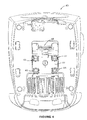
- FIG. 2 is a front view of a portion of the device of FIG. 1 , with the front access panel removed.
- FIG. 3 is a rear view of the device of FIG. 1 .
- FIG. 4 is a bottom view of the device of FIG. 1 .
- FIG. 5 is an exploded perspective view of a second embodiment of an apparatus that may be used in applying neuromuscular electrical stimulation to an agonist/antagonist muscle pair to move a limb about a joint.
- FIG. 6 is a front view of a module which comprises a portion of the apparatus of FIG. 5 .
- FIG. 9 is a perspective view of a patient's arm showing two pairs of electrodes which may be employed in the practice of a preferred embodiment of the invention.
- FIG. 11 is a detailed illustration of one of the patterns of electrical stimulation pulses which may be transmitted to an agonist muscle and the corresponding pattern of electrical stimulation pulses which may be transmitted to the associated antagonist muscle according to a preferred embodiment of the invention.
- the X-axis shows elapsed time and the Y-axis shows the intensity of the electrical stimulation pulses.
- FIGS. 1-4 illustrate a preferred embodiment of a device for generating neuromuscular electrical stimulation for inducing muscle contraction in flexing or abducting a limb at a joint.
- device 20 comprises the main component of a modular system for providing the therapeutic application of energy in multiple forms.
- Device 20 comprises a combination two-channel electrotherapy and ultrasound system, which includes cabinet 22 having display screen 24 .
- Device 20 also includes a user interface in the form of function keys 26 (including keys on both sides of the display screen), which form a part of the interactive interface of the device.
- Other function keys include knob 28 which provides therapy “Intensity Control” and button 30 , which is a therapy session “Start” key.
- FIG. 3 shows the rear of device 20 illustrating system power switch 52 and rear access panel 54 , behind which is located the main power cord (not shown).
- FIG. 3 also shows the location of serial connector outlet jack 56 for connection of a serial device (not shown) such as a hand dynamometry device, an electrogoniometry device or a pressure pad transducer.
- FIG. 4 shows the bottom of device 20 , including a first module receiver which is adapted to receive several types of upgrade modules for enhancing the operation of the system.
- This first module receiver comprises ribbon cable connector 58 to which an associated ribbon cable (not shown) may be attached.
- the first module receiver is adapted to receive an upgrade module such as a rechargeable battery module, a vacuum electrode module (which is adapted to permit the application of electrical stimulation using vacuum electrodes instead of adhesively applied electrodes), a module that is adapted to generate energy in the form of electromagnetic radiation (such as an LLLT module) or other types of upgrade modules.
- an upgrade module such as a rechargeable battery module, a vacuum electrode module (which is adapted to permit the application of electrical stimulation using vacuum electrodes instead of adhesively applied electrodes), a module that is adapted to generate energy in the form of electromagnetic radiation (such as an LLLT module) or other types of upgrade modules.
- a second module receiver 60 which includes PC board contacts 62 , is adapted to receive another type of upgrade module for enhancing the operation of device 20 , such as an EMG module (not shown).
- Attached to device 120 is two-channel electrical stimulation upgrade module 64 for generating the electrical stimulation pulses that are applied through channels 1 and 2 according to the invention.
- Module 64 (also shown in FIGS. 6 and 7 ) includes ribbon cable connector 66 to which is attached one end of ribbon cable 68 .
- the other end of ribbon cable 68 is attached to a first module receiver of device 120 (comprising a ribbon cable connector, not shown, but similar to ribbon cable connector 58 of device 20 ).
- Device 120 also includes front access panel 136 which is similar to, but larger than, front access panel 36 of device 20 . As shown in FIG.
- interface/main controller 90 is the control interface for the user and the primary controller for device 20 (or device 120 and attached module 64 ).
- Major components include a graphic display (such as display screen 24 of device 20 or display screen 124 of device 120 ), display controller, power supply controls, pushbuttons (including function keys 26 of device 20 or function keys 126 of device 120 ), and a power switch (such as power switch 52 of device 20 ).
- this interface allows the user to select the treatment parameters desired and to control the application of neuromuscular electrical stimulation during treatment.
- Stimulator channel 1 controller 104 controls stimulator channel 1 output circuitry 94 which generates the user selected waveform, including the electrical stimulation pulses that are applied through channel 1 according to the invention. Controller 104 controls and monitors both voltage and current passing to the patient through channel 1 , and it provides feedback status information to stimulator main controller 92 .
- Stimulator output circuit 94 for channel 1 is a variable high voltage power supply capable of generating voltages of up to 500 volts and continuous currents as high as 250 mA.
- the patient is connected to the output circuitry through switching devices that deliver stimulation based on the user selected waveform.
- the output can be controlled by maintaining either constant current or constant voltage.
- the output can also be dynamically controlled over time, varying in both amplitude and frequency.
- Stimulator channel 2 controller 106 controls stimulator channel 2 output circuitry 96 which generates the user selected waveform, including the electrical stimulation pulses that are applied through channel 2 according to the invention. Controller 106 controls and monitors both voltage and current passing to the patient through channel 2 . Controller 106 also provides feedback status information to stimulator main controller 92 . Stimulator output circuit 96 for channel 2 is a variable high voltage power supply capable of generating voltages of up to 500 volts and continuous currents as high as 250 mA. The patient is connected to the output circuitry through switching devices that deliver stimulation based on the user selected waveform. Like the output from channel 1 , the output from channel 2 can be controlled by maintaining either constant current or constant voltage.
- the output can also be dynamically controlled over time, varying in both amplitude and frequency.
- the positive (+) output connection from channel 2 can be routed through ultrasound generator 100 to the ultrasound applicator when this mode of operation is selected by use of switch S 1 so that contact 2 is in electrical communication with contact 1 (not shown).
- the invention comprises a method and apparatus for applying neuromuscular electrical stimulation to an agonist/antagonist muscle pair to move a limb about a joint.
- agonist/antagonist muscle pairs may include (among others) the biceps and triceps for moving the forearm about the elbow joint, finger flexors and finger extensors for moving the fingers about various finger joints, the wrist flexors and wrist extensors for moving the hand about the wrist joint, the quadricep and hamstring for moving the lower leg about the knee joint and the anterior tibialis and gastroc/soleus for moving the foot about the ankle joint.
- a device such as device 20 or the device 120 /module 64 combination, is provided for generating a first pattern of neuromuscular electrical stimulation pulses for output through a first channel to a first pair of electrodes and a second pattern of neuromuscular stimulation pulses for output through a second channel to a second pair of electrodes.
- FIG. 9 illustrates the application of electrode 108 and electrode 109 from channel 1 to the skin over the wrist and finger flexor muscles (the agonist) of the forearm, although the relative positions of the electrodes of channel 1 may be reversed, or the electrodes may be placed in different positions. Electrode 108 is operatively attached to channel 1 output circuit 94 (shown in FIG.
- Electrode 112 is operatively attached to channel 2 output circuit 96 (shown in FIG. 8 ) by electrode lead 114 , and electrode 113 is operatively attached to channel 2 output circuit 96 by electrode lead 115 .
- the electrodes from each channel are preferably placed no further apart than the length (or diameter) of the smallest electrode.
- a first pattern 140 of electrical stimulation pulses (shown in FIGS. 10 and 11 ) are generated for transmission through the first pair of electrodes to the agonist muscle, and a second pattern 142 of electrical stimulation pulses are generated for transmission through the second pair of electrodes to the antagonist muscle.
- each first burst period 148 is followed by a rest period 150 which has a duration at least 2-5 times the duration of the preceding first burst period.
- the second pattern 142 of electrical stimulation pulses be generated during a plurality of second burst periods 152 , each of which begins after the beginning of a first burst period and ends no later than (and most preferably simultaneously with) the end of the first burst period.
- each of second burst periods 152 has a duration within the range of 200-5000 msec., and that each second burst period is followed by a rest period or rest interval during which no electrical stimulation pulses are generated for transmission through the second channel.
- each second burst period 152 is followed by a rest period 154 which has a duration at least 2-5 times the duration of the preceding second burst period.
- the first pattern of electrical stimulation pulses be generated or provided in a waveform selected from the group consisting of symmetrical biphasic, asymmetrical biphasic, high volt and premodulated (most preferably symmetrical biphasic), and that the second pattern of electrical stimulation pulses be generated or provided in a waveform selected from the group consisting of symmetrical biphasic, asymmetrical biphasic, high volt and premodulated (most preferably symmetrical biphasic).
- first pulse pattern generating circuit 94 be adapted to generate a first pattern of electrical stimulation pulses having a frequency 144 within the range of 20-80 Hz and an intensity (or intensities) within the range of 10-150 mA.
- second pulse pattern generating circuit 96 be adapted to generate a second pattern of electrical stimulation pulses having a frequency 146 within the range of 20-80 Hz and an intensity (or intensities) within the range of 10-150 mA.
- preferred first pulse pattern generating circuit 94 is adapted to generate a first pattern of electrical stimulation pulses for transmission through a first pair of electrodes 108 and 109 to the agonist muscle at a first intensity level 156 for a period 158 which is sufficient to initiate contraction of the agonist muscle, and at a second intensity level 160 which is less than the first intensity level (and most preferably 75-90% of the first intensity level) for a period 162 that is sufficient to continue contraction of the agonist muscle, and at a third intensity level which is greater than the second intensity level (and most preferably equal to the first intensity level 156 ) for a period 164 that is sufficient to complete contraction of the agonist muscle.
- the first pattern of electrical stimulation pulses may be transmitted at a first intensity level 156 for a period 158 which is sufficient to initiate contraction of the agonist muscle, and at a somewhat lower intermediate intensity level 166 (preferably about 85% of the first intensity level) for a period 168 , and at a second intensity level 160 which is less than the first intensity level (preferably about 80% of the first intensity level) for a period 162 that is sufficient to continue contraction of the agonist muscle, and finally at a third intensity level which is greater than the second intensity level (and preferably equal to the first intensity level 156 ) for a period 164 that is sufficient to complete contraction of the agonist muscle.
- Preferred first pulse pattern generating circuit 94 is also adapted to generate a first pattern of electrical stimulation pulses having period 162 of the second intensity level that is at least three times greater than period 158 of the first intensity level, and a period 164 of the third intensity level that is not greater than period 158 of the first intensity level.
- Preferred second pulse pattern generating circuit 96 is adapted to generate a second pattern of electrical stimulation pulses for transmission through a second pair of electrodes 112 and 113 to the antagonist muscle, at a first intensity level 170 for a period 172 that is sufficient to reduce the acceleration of the limb, and at a second intensity level 174 which is less than the first intensity level (and most preferably 10-30% of the first intensity level) for a period 176 that is sufficient to regulate the movement of the limb, and at a third intensity level which is greater than the second intensity level (and preferably equal to first intensity level 170 ) for a period 178 that is sufficient to stop the movement of the limb.
- Preferred second pulse pattern generating circuit 96 is also adapted to generate a second pattern of electrical stimulation pulses having a period 176 of the second intensity level that is 5-15 times greater than period 172 of the first intensity level and not more than five times greater than the period of the third intensity level, and having a period 178 of the third intensity level that is not more than three times greater than period 172 of the first intensity level.
Abstract
Description
Claims (26)
Priority Applications (3)
| Application Number | Priority Date | Filing Date | Title |
|---|---|---|---|
| US11/706,455 US8620438B1 (en) | 2007-02-13 | 2007-02-13 | Method and apparatus for applying neuromuscular electrical stimulation |
| US14/144,256 US9352151B2 (en) | 2007-02-13 | 2013-12-30 | Method and apparatus for applying neuromuscular electrical stimulation |
| US15/165,414 US9669211B2 (en) | 2007-02-13 | 2016-05-26 | Method and apparatus for applying neuromuscular electrical stimulation |
Applications Claiming Priority (1)
| Application Number | Priority Date | Filing Date | Title |
|---|---|---|---|
| US11/706,455 US8620438B1 (en) | 2007-02-13 | 2007-02-13 | Method and apparatus for applying neuromuscular electrical stimulation |
Related Child Applications (1)
| Application Number | Title | Priority Date | Filing Date |
|---|---|---|---|
| US14/144,256 Continuation US9352151B2 (en) | 2007-02-13 | 2013-12-30 | Method and apparatus for applying neuromuscular electrical stimulation |
Publications (1)
| Publication Number | Publication Date |
|---|---|
| US8620438B1 true US8620438B1 (en) | 2013-12-31 |
Family
ID=49776133
Family Applications (3)
| Application Number | Title | Priority Date | Filing Date |
|---|---|---|---|
| US11/706,455 Active 2028-12-03 US8620438B1 (en) | 2007-02-13 | 2007-02-13 | Method and apparatus for applying neuromuscular electrical stimulation |
| US14/144,256 Active 2027-07-01 US9352151B2 (en) | 2007-02-13 | 2013-12-30 | Method and apparatus for applying neuromuscular electrical stimulation |
| US15/165,414 Active US9669211B2 (en) | 2007-02-13 | 2016-05-26 | Method and apparatus for applying neuromuscular electrical stimulation |
Family Applications After (2)
| Application Number | Title | Priority Date | Filing Date |
|---|---|---|---|
| US14/144,256 Active 2027-07-01 US9352151B2 (en) | 2007-02-13 | 2013-12-30 | Method and apparatus for applying neuromuscular electrical stimulation |
| US15/165,414 Active US9669211B2 (en) | 2007-02-13 | 2016-05-26 | Method and apparatus for applying neuromuscular electrical stimulation |
Country Status (1)
| Country | Link |
|---|---|
| US (3) | US8620438B1 (en) |
Cited By (13)
| Publication number | Priority date | Publication date | Assignee | Title |
|---|---|---|---|---|
| US20160354604A1 (en) * | 2015-06-04 | 2016-12-08 | Invicta Medical, Inc. | Method and apparatus for treating restless legs syndrome |
| US9669211B2 (en) | 2007-02-13 | 2017-06-06 | Encore Medical Asset Corporation | Method and apparatus for applying neuromuscular electrical stimulation |
| EP3231474A1 (en) | 2016-03-31 | 2017-10-18 | Medecell S.A. | Process for establishing a muscular electrostimulation protocol, and respective portable muscular electrostimulation equipment using said protocol |
| CN107735020A (en) * | 2015-06-04 | 2018-02-23 | 因维克塔医药公司 | Method and apparatus for disposing ekbom syndrome |
| EP3269420A4 (en) * | 2015-03-06 | 2018-10-31 | MTG Co., Ltd. | Electrical muscle stimulation device |
| CN110248693A (en) * | 2017-01-18 | 2019-09-17 | 维克托有限公司 | Electrical stimulation apparatus |
| US10512774B2 (en) | 2013-12-18 | 2019-12-24 | University Of Florida Research Foundation, Incorporated | Closed-loop hybrid orthotic system for rehabilitation and functional mobility assistance |
| CN110639126A (en) * | 2019-08-24 | 2020-01-03 | 深圳市倍蓝科技有限公司 | Modulation type muscle electric pulse stimulation method and device |
| US10537733B2 (en) | 2014-06-05 | 2020-01-21 | University Of Florida Research Foundation, Incorporated | Functional electrical stimulation cycling device for people with impaired mobility |
| WO2020106435A1 (en) * | 2018-11-20 | 2020-05-28 | Nuenerchi, Inc. | Electrical stimulation device for applying frequency and peak voltage having inverse relationship |
| US10926088B2 (en) * | 2017-06-27 | 2021-02-23 | JKH Health Co., Ltd. | Portable electronic pulse stimulator with integrated ultrasound and TENS/EMS |
| US11491324B2 (en) | 2019-10-16 | 2022-11-08 | Invicta Medical, Inc. | Adjustable devices for treating sleep apnea, and associated systems and methods |
| US11617888B2 (en) | 2020-11-04 | 2023-04-04 | Invicta Medical, Inc. | Implantable electrodes with remote power delivery for treating sleep apnea, and associated systems and methods |
Families Citing this family (6)
| Publication number | Priority date | Publication date | Assignee | Title |
|---|---|---|---|---|
| JP6751089B2 (en) * | 2014-11-26 | 2020-09-02 | セーフオプ サージカル インコーポレイテッド | Systems and devices |
| CN108348746B (en) | 2015-09-23 | 2021-10-12 | 卡拉健康公司 | System and method for peripheral nerve stimulation in fingers or hands to treat hand tremor |
| US9770587B2 (en) * | 2016-01-13 | 2017-09-26 | Kessler Foundation, Inc. | Neuromuscular stimulation system and method |
| US11344722B2 (en) | 2016-01-21 | 2022-05-31 | Cala Health, Inc. | Systems, methods and devices for peripheral neuromodulation for treating diseases related to overactive bladder |
| EP3740274A4 (en) | 2018-01-17 | 2021-10-27 | Cala Health, Inc. | Systems and methods for treating inflammatory bowel disease through peripheral nerve stimulation |
| US11890468B1 (en) | 2019-10-03 | 2024-02-06 | Cala Health, Inc. | Neurostimulation systems with event pattern detection and classification |
Citations (136)
| Publication number | Priority date | Publication date | Assignee | Title |
|---|---|---|---|---|
| US2263205A (en) | 1939-03-24 | 1941-11-18 | Mine Safety Appliances Co | Apparatus for the treatment of skin diseases |
| US3344792A (en) | 1965-01-13 | 1967-10-03 | Franklin F Offner | Method of muscular stimulation in human beings to aid in walking |
| US3628538A (en) | 1968-09-18 | 1971-12-21 | Nat Res Dev | Apparatus for stimulating muscles controlled by the same muscles |
| US3810457A (en) | 1971-11-24 | 1974-05-14 | Bosch Elektronik Gmbh | Diagnostic apparatus for automatically generating an intensity-time diagram showing points of minimum involuntary muscle movement |
| US3895639A (en) | 1971-09-07 | 1975-07-22 | Rodler Ing Hans | Apparatus for producing an interference signal at a selected location |
| US3918459A (en) | 1972-04-17 | 1975-11-11 | Sybron Corp | Constant current electrotherapy device with plug-in current control means |
| US4019518A (en) | 1975-08-11 | 1977-04-26 | Medtronic, Inc. | Electrical stimulation system |
| US4068669A (en) | 1975-11-24 | 1978-01-17 | Stimulation Technology, Inc. | Stimulator fault protection circuit |
| US4088141A (en) | 1976-04-27 | 1978-05-09 | Stimulation Technology, Inc. | Fault circuit for stimulator |
| US4164740A (en) | 1976-03-04 | 1979-08-14 | Constant James N | Synthetic aperture using image scanner |
| US4165750A (en) | 1978-03-18 | 1979-08-28 | Aleev Leonid S | Bioelectrically controlled electric stimulator of human muscles |
| US4177819A (en) | 1978-03-30 | 1979-12-11 | Kofsky Harvey I | Muscle stimulating apparatus |
| US4256116A (en) | 1978-07-03 | 1981-03-17 | Technion Research And Development Foundation, Limited | Transcutaneous pain reliever |
| US4324253A (en) | 1977-01-28 | 1982-04-13 | Greene Ronald W | Transcutaneous pain control and/or muscle stimulating apparatus |
| US4342317A (en) | 1980-04-01 | 1982-08-03 | The Professional Staff Association Of The Rancho Los Amigos Hospital, Inc. | Method of electrical muscle stimulation for treatment of scoliosis and other spinal deformities |
| FR2504807A1 (en) | 1981-04-30 | 1982-11-05 | Medtronic Inc | NERVOUS STIMULATOR WITH KEYBOARD-CONTROLLED MICROPROCESSOR |
| US4363324A (en) | 1979-08-31 | 1982-12-14 | Siemens Aktiengesellschaft | Electromedical apparatus |
| US4372319A (en) | 1979-06-15 | 1983-02-08 | Matsushita Electric Works, Ltd. | Low frequency therapeutic instrument |
| US4390023A (en) | 1981-04-30 | 1983-06-28 | Medtronic, Inc. | Patterned electrical tissue stimulator |
| US4392496A (en) | 1981-03-13 | 1983-07-12 | Medtronic, Inc. | Neuromuscular stimulator |
| US4408609A (en) | 1980-04-01 | 1983-10-11 | Professional Staff Association Of The Rancho Los Amigos Hospital, Inc. | Electrical muscle stimulation for treatment of scoliosis and other spinal deformities |
| DE3216911A1 (en) | 1982-05-06 | 1983-11-10 | Datron-Electronic Pichl & Schulte KG, 6109 Mühltal | Domiciliary apparatus for electro-therapeutic treatment |
| US4503863A (en) | 1979-06-29 | 1985-03-12 | Katims Jefferson J | Method and apparatus for transcutaneous electrical stimulation |
| US4535777A (en) | 1981-08-20 | 1985-08-20 | Physio Technology, Inc. | Method of providing electrical stimulation of tissue |
| US4569352A (en) | 1983-05-13 | 1986-02-11 | Wright State University | Feedback control system for walking |
| US4580339A (en) | 1982-08-05 | 1986-04-08 | Empi, Inc. | Method for fabricating a disposable electrode for transcutaneous nerve stimulator |
| US4582063A (en) | 1984-06-05 | 1986-04-15 | Codman & Shurtleff, Inc. | Transcutaneous nerve stimulation device with sentinel |
| US4586495A (en) | 1984-07-02 | 1986-05-06 | Wright State University | Therapy system for acute patient care |
| US4614178A (en) | 1981-05-06 | 1986-09-30 | Orvosi Muszerszovetkezet | Automatic dose meter and control circuit arrangement |
| US4632117A (en) | 1982-08-09 | 1986-12-30 | Staodynamics, Inc. | Simplified transcutaneous nerve stimulating device |
| US4640286A (en) | 1984-11-02 | 1987-02-03 | Staodynamics, Inc. | Optimized nerve fiber stimulation |
| US4664118A (en) | 1982-08-30 | 1987-05-12 | Batters Robert C | Electrical therapeutic assembly and method for reducing pain and edema in a human body |
| US4669477A (en) | 1985-05-20 | 1987-06-02 | Empi, Inc. | Apparatus and method for preventing bruxism |
| US4690145A (en) | 1985-06-17 | 1987-09-01 | Minnesota Mining And Manufacturing Company | Output limited electrical stimulator for biological tissue |
| US4706674A (en) | 1985-06-17 | 1987-11-17 | Minnesota Mining And Manufacturing Co. | Electrical stimulator for biological tissue utilizing output current monitor |
| US4769881A (en) | 1986-09-02 | 1988-09-13 | Pedigo Irby R | High precision tens apparatus and method of use |
| US4785813A (en) | 1986-02-18 | 1988-11-22 | Wright State University | Apparatus for assisting muscular contraction |
| US4805636A (en) | 1986-02-24 | 1989-02-21 | The University Of Michigan | System for controlling muscle response |
| US4811742A (en) | 1985-06-11 | 1989-03-14 | Verimed, Inc. | Proportional response electrical muscle stimulation |
| US4848347A (en) | 1988-04-04 | 1989-07-18 | Dynatronics Laser Corporation | Interferential electrical current therapy systems and methods |
| US4887603A (en) | 1985-07-22 | 1989-12-19 | Empi, Inc. | Medical stimulator with stimulation signal characteristics modulated as a function of stimulation signal frequency |
| US4919139A (en) | 1985-04-03 | 1990-04-24 | Medicomex S.A. | Electrical neuromuscular stimulation device |
| US4926865A (en) | 1987-10-01 | 1990-05-22 | Oman Paul S | Microcomputer-based nerve and muscle stimulator |
| US4976264A (en) * | 1989-05-10 | 1990-12-11 | Therapeutic Technologies Inc. | Power muscle stimulator |
| US4977895A (en) * | 1989-05-22 | 1990-12-18 | Ely Shavit Pasternak | Electrical apparatus for medical treatment |
| US4996987A (en) | 1989-05-10 | 1991-03-05 | Therapeutic Technologies Inc. | Power muscle stimulator |
| US5041974A (en) | 1988-10-26 | 1991-08-20 | Walker Judith B | Multichannel stimulator for tuned stimulation |
| US5048522A (en) | 1990-04-13 | 1991-09-17 | Therapeutic Technologies, Inc. | Power muscle stimulator |
| US5067478A (en) | 1988-06-21 | 1991-11-26 | Berlant Stephen R | Structure and method of manufacturing an electrode glove for applying electro-massage and electro-acupressure to patients |
| US5067495A (en) | 1989-09-27 | 1991-11-26 | Brehm Richard L | Electro wave therapy |
| US5070873A (en) | 1987-02-13 | 1991-12-10 | Sigmedics, Inc. | Method of and apparatus for electrically stimulating quadriceps muscles of an upper motor unit paraplegic |
| US5081989A (en) | 1989-04-07 | 1992-01-21 | Sigmedics, Inc. | Microprocessor-controlled enhanced multiplexed functional electrical stimulator for surface stimulation in paralyzed patients |
| US5092329A (en) | 1989-04-07 | 1992-03-03 | Sigmedics, Inc. | Microprocessor-controlled multiplexed functional electrical stimulator for surface stimulation in paralyzed patients with safety enhancements |
| US5113176A (en) | 1990-11-13 | 1992-05-12 | Staodyn, Inc. | Lumbar roll with audible alerting capability |
| US5117826A (en) | 1987-02-02 | 1992-06-02 | Staodyn, Inc. | Combined nerve fiber and body tissue stimulation apparatus and method |
| US5123413A (en) | 1987-05-27 | 1992-06-23 | Teijin Limited | Electric therapeutic apparatus |
| US5131401A (en) | 1990-09-10 | 1992-07-21 | Axon Medical Inc. | Method and apparatus for monitoring neuromuscular blockage |
| US5161530A (en) | 1990-03-16 | 1992-11-10 | Gamble James J | Interferential therapy employing switching mechanism |
| US5178156A (en) | 1989-06-20 | 1993-01-12 | Chest Corporation | Apnea preventive stimulating device |
| US5184617A (en) | 1990-06-05 | 1993-02-09 | Staodyn, Inc. | Output pulse compensation for therapeutic-type electronic devices |
| EP0269844B1 (en) | 1986-11-07 | 1993-06-16 | Siemens Aktiengesellschaft | Stimulator |
| US5233987A (en) | 1992-07-09 | 1993-08-10 | Empi, Inc. | System and method for monitoring patient's compliance |
| EP0367338B1 (en) | 1988-10-31 | 1993-08-11 | Ingenieursburo Uniphy B.V. | Electrotherapy apparatus |
| US5285781A (en) | 1990-05-26 | 1994-02-15 | Stiwell S. A. | Electrical neuromuscular stimulation device |
| US5300096A (en) | 1992-06-03 | 1994-04-05 | Hall H Eugene | Electromyographic treatment device |
| US5350414A (en) | 1991-12-10 | 1994-09-27 | Electro Science Technologies, Inc. | Local application microprocessor based nerve and muscle stimulator |
| US5397338A (en) | 1993-03-29 | 1995-03-14 | Maven Labs, Inc. | Electrotherapy device |
| US5413550A (en) | 1993-07-21 | 1995-05-09 | Pti, Inc. | Ultrasound therapy system with automatic dose control |
| US5507788A (en) * | 1994-08-11 | 1996-04-16 | The Regents Of The University Of California | Method and apparatus for controlling skeletal muscle fatigue during electrical stimulation |
| EP0706806A1 (en) | 1993-03-08 | 1996-04-17 | Valmed SA | Device for trophic stimulation of muscles |
| US5512057A (en) | 1994-11-14 | 1996-04-30 | Medserv Group, Inc. | Interferential stimulator for applying localized stimulation |
| US5514165A (en) | 1993-12-23 | 1996-05-07 | Jace Systems, Inc. | Combined high voltage pulsed current and neuromuscular stimulation electrotherapy device |
| US5540735A (en) | 1994-12-12 | 1996-07-30 | Rehabilicare, Inc. | Apparatus for electro-stimulation of flexing body portions |
| US5540235A (en) | 1994-06-30 | 1996-07-30 | Wilson; John R. | Adaptor for neurophysiological monitoring with a personal computer |
| US5562718A (en) | 1994-06-03 | 1996-10-08 | Palermo; Francis X. | Electronic neuromuscular stimulation device |
| DE4092175T1 (en) | 1989-11-30 | 1997-07-31 | Mitsubishi Motors Corp | Device for controlling an idle change |
| US5653739A (en) | 1995-09-13 | 1997-08-05 | Empi, Inc. | Electronic pain feedback system and method |
| US5732401A (en) | 1996-03-29 | 1998-03-24 | Intellitecs International Ltd. | Activity based cost tracking systems |
| US5748845A (en) | 1995-07-31 | 1998-05-05 | Motorola, Inc. | FES method and system for controlling the movement of a limb |
| US5755745A (en) | 1995-09-29 | 1998-05-26 | International Rehabilitative Sciences, Inc. | Portable muscle stimulator with removable data storage card |
| US5776173A (en) | 1997-06-04 | 1998-07-07 | Madsen, Jr.; Ronald E. | Programmable interferential stimulator |
| US5775331A (en) | 1995-06-07 | 1998-07-07 | Uromed Corporation | Apparatus and method for locating a nerve |
| US5776171A (en) | 1994-09-06 | 1998-07-07 | Case Western Reserve University | Functional neuromuscular stimulation system |
| US5782893A (en) | 1996-02-26 | 1998-07-21 | J.D. Medical, Inc. | Neuromuscular electrical stimulator for deep vein thrombosis treatment |
| US5800458A (en) | 1996-09-30 | 1998-09-01 | Rehabilicare, Inc. | Compliance monitor for monitoring applied electrical stimulation |
| US5817138A (en) | 1996-11-27 | 1998-10-06 | Suzuki; James Y. | Multi-channel, interferential wave, micro current device and methods for treatment using micro current |
| US5961542A (en) | 1998-02-11 | 1999-10-05 | Empi Corp. | Medical stimulator with intensity control and mode of operation override |
| US5967975A (en) | 1997-11-13 | 1999-10-19 | Ridgeway; Donald G. | Home health parameter monitoring system |
| US5980435A (en) | 1993-07-09 | 1999-11-09 | Kinetecs, Inc. | Methods of therapy or controlled exercise using a jointed brace |
| US6026328A (en) | 1986-03-24 | 2000-02-15 | Case Western Reserve University | Functional neuromuscular stimulation system with shielded percutaneous interface |
| US6029090A (en) | 1997-01-27 | 2000-02-22 | Herbst; Ewa | Multi-functional electrical stimulation system |
| US6041259A (en) | 1997-12-12 | 2000-03-21 | Empi, Inc. | Externally worn medical device |
| US6044303A (en) | 1995-09-13 | 2000-03-28 | Empi Corp. | TENS device with electronic pain intensity scale |
| US6064911A (en) | 1997-08-08 | 2000-05-16 | Rehabilicare, Inc. | Device using both HVPC and NMS electrotherapy |
| US6086525A (en) | 1994-11-28 | 2000-07-11 | Neotonus, Inc. | Magnetic nerve stimulator for exciting peripheral nerves |
| US6113552A (en) | 1998-11-18 | 2000-09-05 | International Medical Device Partners, Inc. | Pain measurement system and method |
| US6146335A (en) | 1997-07-01 | 2000-11-14 | Neurometrix, Inc. | Apparatus for methods for the assessment of neuromuscular function of the lower extremity |
| US6233472B1 (en) | 1995-06-06 | 2001-05-15 | Patient Comfort, L.L.C. | Electrode assembly and method for signaling a monitor |
| US6285906B1 (en) | 1999-05-26 | 2001-09-04 | Impulse Dynamics N. V. | Muscle contraction assist device |
| DE19545238C2 (en) | 1995-11-22 | 2001-09-06 | Weis Lutz Michael | Stimulation device with electrodes contacting the skin surface and power supply and / or control unit releasably attached to it |
| US6292692B1 (en) | 1999-04-30 | 2001-09-18 | Medical Research Laboratories, Inc. | Medical treatment device with functions, operated under passcode control |
| US6324432B1 (en) | 1999-11-01 | 2001-11-27 | Compex Sa | Electrical neuromuscular stimulator for measuring muscle responses to electrical stimulation pulses |
| US20010051787A1 (en) | 1999-07-07 | 2001-12-13 | Markus Haller | System and method of automated invoicing for communications between an implantable medical device and a remote computer system or health care provider |
| US6393328B1 (en) | 2000-05-08 | 2002-05-21 | International Rehabilitative Sciences, Inc. | Multi-functional portable electro-medical device |
| US6432074B1 (en) | 1997-05-10 | 2002-08-13 | Smith & Nephew Plc | Extension indicators |
| US6445955B1 (en) | 1999-07-08 | 2002-09-03 | Stephen A. Michelson | Miniature wireless transcutaneous electrical neuro or muscular-stimulation unit |
| US20020165590A1 (en) * | 2001-01-16 | 2002-11-07 | Crowe Louis Michael | Apparatus for stimulating a muscle of a subject |
| US20030036683A1 (en) | 2000-05-01 | 2003-02-20 | Kehr Bruce A. | Method, system and computer program product for internet-enabled, patient monitoring system |
| US20030065370A1 (en) | 2000-01-21 | 2003-04-03 | Lebel Ronald J. | Ambulatory medical apparatus with hand held communication device |
| US20030074037A1 (en) | 2001-10-17 | 2003-04-17 | Rehabilicare, Inc. | Electrical nerve stimulation device |
| US6560487B1 (en) | 2000-05-08 | 2003-05-06 | International Rehabilitative Sciences, Inc. | Electro-medical device for use with biologics |
| US6564103B2 (en) | 2000-12-01 | 2003-05-13 | Visionquest Industries, Inc. | Electrical stimulator and method of use |
| US6584358B2 (en) | 2000-01-07 | 2003-06-24 | Biowave Corporation | Electro therapy method and apparatus |
| US20030120323A1 (en) | 1999-07-27 | 2003-06-26 | Meadows Paul M. | Rechargeable spinal cord stimulator system |
| US6609031B1 (en) | 1996-06-07 | 2003-08-19 | Advanced Neuromodulation Systems, Inc. | Multiprogrammable tissue stimulator and method |
| US6612984B1 (en) | 1999-12-03 | 2003-09-02 | Kerr, Ii Robert A. | System and method for collecting and transmitting medical data |
| US6628492B2 (en) | 2000-05-16 | 2003-09-30 | Nihon Kohden Corporation | Disarm circuit using semiconductor switch device |
| US6647290B2 (en) | 2000-01-18 | 2003-11-11 | Koninklijke Philips Electronics N.V. | Charge-based defibrillation method and apparatus |
| US6662051B1 (en) | 2000-03-31 | 2003-12-09 | Stephen A. Eraker | Programmable pain reduction device |
| US6675048B2 (en) | 2000-05-08 | 2004-01-06 | International Rehabilitative Sciences, Inc. | Electro-medical device for use with biologics |
| US20040010291A1 (en) | 2002-07-12 | 2004-01-15 | Wagner Darrell O. | Method and apparatus for assessing and treating atrial fibrillation risk |
| WO2004011087A1 (en) | 2002-07-29 | 2004-02-05 | Patents Exploitation Company B.V. | System designed to generate programmed sequences of stimuli resulting in controlled and persistent physiological responses in the body |
| US6701189B2 (en) | 2001-03-30 | 2004-03-02 | Neurocontrol Corporation | Systems and methods for performing prosthetic or therapeutic neuromuscular stimulation using a universal external controller accommodating different control inputs and/or different control outputs |
| WO2004018038A1 (en) | 2002-08-22 | 2004-03-04 | Compex Medical S.A. | System for fixing a biomedical electrode |
| JP2004081676A (en) | 2002-08-28 | 2004-03-18 | Yaskawa Electric Corp | Biofeedback apparatus and method |
| US6727814B2 (en) | 2001-09-24 | 2004-04-27 | Medtronic Physio-Control Manufacturing Corp. | System, method and apparatus for sensing and communicating status information from a portable medical device |
| US20040147975A1 (en) * | 2001-04-24 | 2004-07-29 | Popovic Dejan P. | Functional electrical therapy system (fets) |
| US20040167585A1 (en) | 2003-02-26 | 2004-08-26 | Kovak Stanley J. | Neuro-muscular stimulation system |
| US6826429B2 (en) | 2001-01-19 | 2004-11-30 | Dynatronics Corporation | Interferential current treatment apparatus |
| US6839594B2 (en) | 2001-04-26 | 2005-01-04 | Biocontrol Medical Ltd | Actuation and control of limbs through motor nerve stimulation |
| US6845271B2 (en) | 1998-06-03 | 2005-01-18 | Neurocontrol Corporation | Treatment of shoulder dysfunction using a percutaneous intramuscular stimulation system |
| US20050055054A1 (en) | 2003-09-10 | 2005-03-10 | Tsung-I Yu | Binding cloth for medium or low frequency wave massage |
| US6876883B2 (en) | 2002-08-26 | 2005-04-05 | Arthur F. Hurtado | Method for applying variable electro-muscle stimulation and system therefor |
| US6907295B2 (en) | 2001-08-31 | 2005-06-14 | Biocontrol Medical Ltd. | Electrode assembly for nerve control |
| US6963773B2 (en) | 1997-03-05 | 2005-11-08 | Medtronic Physio-Control Manufacturing Corp. | H-bridge circuit for generating a high-energy biphasic waveform in an external defibrillator using single SCR and IGBT switches in an integrated package |
| EP1095670B1 (en) | 1999-10-29 | 2008-05-07 | Compex Medical S.A | Neuromuscular stimulator with measurement of the muscular response on the electrical stimulation impulse |
Family Cites Families (11)
| Publication number | Priority date | Publication date | Assignee | Title |
|---|---|---|---|---|
| US4419998A (en) | 1980-08-08 | 1983-12-13 | R2 Corporation | Physiological electrode systems |
| JPS62501192A (en) | 1984-10-23 | 1987-05-14 | ジオン フアウンデ−シヨン | Electric therapy signal supply method and device |
| GB9321086D0 (en) | 1993-10-13 | 1993-12-01 | Univ Alberta | Hand stimulator |
| CA2217920A1 (en) | 1997-10-08 | 1999-04-08 | Neuromotion Inc. | Garment having controller that is activated by mechanical impact |
| AU2762899A (en) | 1998-02-17 | 1999-08-30 | Southern Research Institute | Patient data acquisition unit and data support system |
| DE19828518A1 (en) | 1998-06-26 | 1999-12-30 | Bosch Gmbh Robert | Rectifier modular unit on a three-phase alternator |
| WO2000036900A2 (en) | 1998-12-18 | 2000-06-29 | Louise Fourie | Method and system for monitoring and communicating data over a wireless network |
| US6937905B2 (en) | 2002-08-02 | 2005-08-30 | International Rehabilitative Coion Sciences, Inc. | Osteogenesis stimulator with digital signal processing |
| US8977363B2 (en) | 2003-01-22 | 2015-03-10 | Meagan Medical, Inc. | Spinal cord stimulation with interferential current |
| CN1758891B (en) * | 2003-03-13 | 2012-10-10 | 自然美有限公司 | Cellulite ultrasound treatment |
| US8620438B1 (en) | 2007-02-13 | 2013-12-31 | Encore Medical Asset Corporation | Method and apparatus for applying neuromuscular electrical stimulation |
-
2007
- 2007-02-13 US US11/706,455 patent/US8620438B1/en active Active
-
2013
- 2013-12-30 US US14/144,256 patent/US9352151B2/en active Active
-
2016
- 2016-05-26 US US15/165,414 patent/US9669211B2/en active Active
Patent Citations (145)
| Publication number | Priority date | Publication date | Assignee | Title |
|---|---|---|---|---|
| US2263205A (en) | 1939-03-24 | 1941-11-18 | Mine Safety Appliances Co | Apparatus for the treatment of skin diseases |
| US3344792A (en) | 1965-01-13 | 1967-10-03 | Franklin F Offner | Method of muscular stimulation in human beings to aid in walking |
| US3628538A (en) | 1968-09-18 | 1971-12-21 | Nat Res Dev | Apparatus for stimulating muscles controlled by the same muscles |
| US3895639A (en) | 1971-09-07 | 1975-07-22 | Rodler Ing Hans | Apparatus for producing an interference signal at a selected location |
| US3810457A (en) | 1971-11-24 | 1974-05-14 | Bosch Elektronik Gmbh | Diagnostic apparatus for automatically generating an intensity-time diagram showing points of minimum involuntary muscle movement |
| US3918459A (en) | 1972-04-17 | 1975-11-11 | Sybron Corp | Constant current electrotherapy device with plug-in current control means |
| US4019518A (en) | 1975-08-11 | 1977-04-26 | Medtronic, Inc. | Electrical stimulation system |
| US4068669A (en) | 1975-11-24 | 1978-01-17 | Stimulation Technology, Inc. | Stimulator fault protection circuit |
| US4164740A (en) | 1976-03-04 | 1979-08-14 | Constant James N | Synthetic aperture using image scanner |
| US4088141A (en) | 1976-04-27 | 1978-05-09 | Stimulation Technology, Inc. | Fault circuit for stimulator |
| US4324253A (en) | 1977-01-28 | 1982-04-13 | Greene Ronald W | Transcutaneous pain control and/or muscle stimulating apparatus |
| US4165750A (en) | 1978-03-18 | 1979-08-28 | Aleev Leonid S | Bioelectrically controlled electric stimulator of human muscles |
| FR2425865B1 (en) | 1978-03-18 | 1981-04-30 | Inst Kib Akademii | |
| US4177819A (en) | 1978-03-30 | 1979-12-11 | Kofsky Harvey I | Muscle stimulating apparatus |
| US4256116A (en) | 1978-07-03 | 1981-03-17 | Technion Research And Development Foundation, Limited | Transcutaneous pain reliever |
| US4372319A (en) | 1979-06-15 | 1983-02-08 | Matsushita Electric Works, Ltd. | Low frequency therapeutic instrument |
| US4503863A (en) | 1979-06-29 | 1985-03-12 | Katims Jefferson J | Method and apparatus for transcutaneous electrical stimulation |
| US4363324A (en) | 1979-08-31 | 1982-12-14 | Siemens Aktiengesellschaft | Electromedical apparatus |
| US4342317A (en) | 1980-04-01 | 1982-08-03 | The Professional Staff Association Of The Rancho Los Amigos Hospital, Inc. | Method of electrical muscle stimulation for treatment of scoliosis and other spinal deformities |
| US4408609A (en) | 1980-04-01 | 1983-10-11 | Professional Staff Association Of The Rancho Los Amigos Hospital, Inc. | Electrical muscle stimulation for treatment of scoliosis and other spinal deformities |
| US4392496A (en) | 1981-03-13 | 1983-07-12 | Medtronic, Inc. | Neuromuscular stimulator |
| US4390023A (en) | 1981-04-30 | 1983-06-28 | Medtronic, Inc. | Patterned electrical tissue stimulator |
| FR2504807A1 (en) | 1981-04-30 | 1982-11-05 | Medtronic Inc | NERVOUS STIMULATOR WITH KEYBOARD-CONTROLLED MICROPROCESSOR |
| US4614178A (en) | 1981-05-06 | 1986-09-30 | Orvosi Muszerszovetkezet | Automatic dose meter and control circuit arrangement |
| US4535777A (en) | 1981-08-20 | 1985-08-20 | Physio Technology, Inc. | Method of providing electrical stimulation of tissue |
| DE3216911A1 (en) | 1982-05-06 | 1983-11-10 | Datron-Electronic Pichl & Schulte KG, 6109 Mühltal | Domiciliary apparatus for electro-therapeutic treatment |
| US4580339A (en) | 1982-08-05 | 1986-04-08 | Empi, Inc. | Method for fabricating a disposable electrode for transcutaneous nerve stimulator |
| US4632117A (en) | 1982-08-09 | 1986-12-30 | Staodynamics, Inc. | Simplified transcutaneous nerve stimulating device |
| US4664118A (en) | 1982-08-30 | 1987-05-12 | Batters Robert C | Electrical therapeutic assembly and method for reducing pain and edema in a human body |
| US4569352A (en) | 1983-05-13 | 1986-02-11 | Wright State University | Feedback control system for walking |
| US4582063A (en) | 1984-06-05 | 1986-04-15 | Codman & Shurtleff, Inc. | Transcutaneous nerve stimulation device with sentinel |
| US4586495A (en) | 1984-07-02 | 1986-05-06 | Wright State University | Therapy system for acute patient care |
| US4640286A (en) | 1984-11-02 | 1987-02-03 | Staodynamics, Inc. | Optimized nerve fiber stimulation |
| US4803988A (en) | 1984-11-02 | 1989-02-14 | Staodynamics, Inc. | Nerve fiber stimulation using plural equally active electrodes |
| US4919139A (en) | 1985-04-03 | 1990-04-24 | Medicomex S.A. | Electrical neuromuscular stimulation device |
| US4669477A (en) | 1985-05-20 | 1987-06-02 | Empi, Inc. | Apparatus and method for preventing bruxism |
| US4811742A (en) | 1985-06-11 | 1989-03-14 | Verimed, Inc. | Proportional response electrical muscle stimulation |
| US4690145A (en) | 1985-06-17 | 1987-09-01 | Minnesota Mining And Manufacturing Company | Output limited electrical stimulator for biological tissue |
| US4706674A (en) | 1985-06-17 | 1987-11-17 | Minnesota Mining And Manufacturing Co. | Electrical stimulator for biological tissue utilizing output current monitor |
| US4887603A (en) | 1985-07-22 | 1989-12-19 | Empi, Inc. | Medical stimulator with stimulation signal characteristics modulated as a function of stimulation signal frequency |
| US4785813A (en) | 1986-02-18 | 1988-11-22 | Wright State University | Apparatus for assisting muscular contraction |
| US4805636A (en) | 1986-02-24 | 1989-02-21 | The University Of Michigan | System for controlling muscle response |
| US6026328A (en) | 1986-03-24 | 2000-02-15 | Case Western Reserve University | Functional neuromuscular stimulation system with shielded percutaneous interface |
| US4769881A (en) | 1986-09-02 | 1988-09-13 | Pedigo Irby R | High precision tens apparatus and method of use |
| EP0269844B1 (en) | 1986-11-07 | 1993-06-16 | Siemens Aktiengesellschaft | Stimulator |
| US5117826A (en) | 1987-02-02 | 1992-06-02 | Staodyn, Inc. | Combined nerve fiber and body tissue stimulation apparatus and method |
| US5070873A (en) | 1987-02-13 | 1991-12-10 | Sigmedics, Inc. | Method of and apparatus for electrically stimulating quadriceps muscles of an upper motor unit paraplegic |
| US5123413A (en) | 1987-05-27 | 1992-06-23 | Teijin Limited | Electric therapeutic apparatus |
| US4926865A (en) | 1987-10-01 | 1990-05-22 | Oman Paul S | Microcomputer-based nerve and muscle stimulator |
| US4848347A (en) | 1988-04-04 | 1989-07-18 | Dynatronics Laser Corporation | Interferential electrical current therapy systems and methods |
| US5067478A (en) | 1988-06-21 | 1991-11-26 | Berlant Stephen R | Structure and method of manufacturing an electrode glove for applying electro-massage and electro-acupressure to patients |
| US5041974A (en) | 1988-10-26 | 1991-08-20 | Walker Judith B | Multichannel stimulator for tuned stimulation |
| EP0367338B1 (en) | 1988-10-31 | 1993-08-11 | Ingenieursburo Uniphy B.V. | Electrotherapy apparatus |
| US5081989A (en) | 1989-04-07 | 1992-01-21 | Sigmedics, Inc. | Microprocessor-controlled enhanced multiplexed functional electrical stimulator for surface stimulation in paralyzed patients |
| US5092329A (en) | 1989-04-07 | 1992-03-03 | Sigmedics, Inc. | Microprocessor-controlled multiplexed functional electrical stimulator for surface stimulation in paralyzed patients with safety enhancements |
| US4996987A (en) | 1989-05-10 | 1991-03-05 | Therapeutic Technologies Inc. | Power muscle stimulator |
| US4976264A (en) * | 1989-05-10 | 1990-12-11 | Therapeutic Technologies Inc. | Power muscle stimulator |
| US4977895A (en) * | 1989-05-22 | 1990-12-18 | Ely Shavit Pasternak | Electrical apparatus for medical treatment |
| US5178156A (en) | 1989-06-20 | 1993-01-12 | Chest Corporation | Apnea preventive stimulating device |
| US5067495A (en) | 1989-09-27 | 1991-11-26 | Brehm Richard L | Electro wave therapy |
| DE4092175T1 (en) | 1989-11-30 | 1997-07-31 | Mitsubishi Motors Corp | Device for controlling an idle change |
| US5161530A (en) | 1990-03-16 | 1992-11-10 | Gamble James J | Interferential therapy employing switching mechanism |
| US5048522A (en) | 1990-04-13 | 1991-09-17 | Therapeutic Technologies, Inc. | Power muscle stimulator |
| US5285781A (en) | 1990-05-26 | 1994-02-15 | Stiwell S. A. | Electrical neuromuscular stimulation device |
| US5184617A (en) | 1990-06-05 | 1993-02-09 | Staodyn, Inc. | Output pulse compensation for therapeutic-type electronic devices |
| USRE35987E (en) | 1990-06-05 | 1998-12-08 | Staodyn, Inc. | Output pulse compensation for therapeutic-type electronic devices |
| US5131401A (en) | 1990-09-10 | 1992-07-21 | Axon Medical Inc. | Method and apparatus for monitoring neuromuscular blockage |
| US5113176A (en) | 1990-11-13 | 1992-05-12 | Staodyn, Inc. | Lumbar roll with audible alerting capability |
| US5350414A (en) | 1991-12-10 | 1994-09-27 | Electro Science Technologies, Inc. | Local application microprocessor based nerve and muscle stimulator |
| US5300096A (en) | 1992-06-03 | 1994-04-05 | Hall H Eugene | Electromyographic treatment device |
| US5233987A (en) | 1992-07-09 | 1993-08-10 | Empi, Inc. | System and method for monitoring patient's compliance |
| EP0706806A1 (en) | 1993-03-08 | 1996-04-17 | Valmed SA | Device for trophic stimulation of muscles |
| US5397338A (en) | 1993-03-29 | 1995-03-14 | Maven Labs, Inc. | Electrotherapy device |
| US5980435A (en) | 1993-07-09 | 1999-11-09 | Kinetecs, Inc. | Methods of therapy or controlled exercise using a jointed brace |
| US5413550A (en) | 1993-07-21 | 1995-05-09 | Pti, Inc. | Ultrasound therapy system with automatic dose control |
| US5514165A (en) | 1993-12-23 | 1996-05-07 | Jace Systems, Inc. | Combined high voltage pulsed current and neuromuscular stimulation electrotherapy device |
| US5562718A (en) | 1994-06-03 | 1996-10-08 | Palermo; Francis X. | Electronic neuromuscular stimulation device |
| US5540235A (en) | 1994-06-30 | 1996-07-30 | Wilson; John R. | Adaptor for neurophysiological monitoring with a personal computer |
| US5507788A (en) * | 1994-08-11 | 1996-04-16 | The Regents Of The University Of California | Method and apparatus for controlling skeletal muscle fatigue during electrical stimulation |
| US5954758A (en) | 1994-09-06 | 1999-09-21 | Case Western Reserve University | Functional neuromuscular stimulation system |
| US5776171A (en) | 1994-09-06 | 1998-07-07 | Case Western Reserve University | Functional neuromuscular stimulation system |
| US5512057A (en) | 1994-11-14 | 1996-04-30 | Medserv Group, Inc. | Interferential stimulator for applying localized stimulation |
| US6086525A (en) | 1994-11-28 | 2000-07-11 | Neotonus, Inc. | Magnetic nerve stimulator for exciting peripheral nerves |
| US5540735A (en) | 1994-12-12 | 1996-07-30 | Rehabilicare, Inc. | Apparatus for electro-stimulation of flexing body portions |
| US6233472B1 (en) | 1995-06-06 | 2001-05-15 | Patient Comfort, L.L.C. | Electrode assembly and method for signaling a monitor |
| US5775331A (en) | 1995-06-07 | 1998-07-07 | Uromed Corporation | Apparatus and method for locating a nerve |
| US5748845A (en) | 1995-07-31 | 1998-05-05 | Motorola, Inc. | FES method and system for controlling the movement of a limb |
| US5873900A (en) | 1995-09-13 | 1999-02-23 | Empi, Inc. | Electronic pain feedback system and method |
| US6044303A (en) | 1995-09-13 | 2000-03-28 | Empi Corp. | TENS device with electronic pain intensity scale |
| US5653739A (en) | 1995-09-13 | 1997-08-05 | Empi, Inc. | Electronic pain feedback system and method |
| USRE36690E (en) | 1995-09-29 | 2000-05-16 | International Rehabilitative Sciences, Inc. | Portable muscle stimulator with pulse width control |
| US5836995A (en) | 1995-09-29 | 1998-11-17 | International Rehabilitative Sciences, Inc. | Portable muscle stimulator with pulse width control |
| US5755745A (en) | 1995-09-29 | 1998-05-26 | International Rehabilitative Sciences, Inc. | Portable muscle stimulator with removable data storage card |
| DE19545238C2 (en) | 1995-11-22 | 2001-09-06 | Weis Lutz Michael | Stimulation device with electrodes contacting the skin surface and power supply and / or control unit releasably attached to it |
| US5782893A (en) | 1996-02-26 | 1998-07-21 | J.D. Medical, Inc. | Neuromuscular electrical stimulator for deep vein thrombosis treatment |
| US5732401A (en) | 1996-03-29 | 1998-03-24 | Intellitecs International Ltd. | Activity based cost tracking systems |
| US6609031B1 (en) | 1996-06-07 | 2003-08-19 | Advanced Neuromodulation Systems, Inc. | Multiprogrammable tissue stimulator and method |
| US5800458A (en) | 1996-09-30 | 1998-09-01 | Rehabilicare, Inc. | Compliance monitor for monitoring applied electrical stimulation |
| US5817138A (en) | 1996-11-27 | 1998-10-06 | Suzuki; James Y. | Multi-channel, interferential wave, micro current device and methods for treatment using micro current |
| US6029090A (en) | 1997-01-27 | 2000-02-22 | Herbst; Ewa | Multi-functional electrical stimulation system |
| US6684106B2 (en) | 1997-01-27 | 2004-01-27 | Ewa Herbst | Method and electronic components for multi-functional electrical stimulation systems |
| US6963773B2 (en) | 1997-03-05 | 2005-11-08 | Medtronic Physio-Control Manufacturing Corp. | H-bridge circuit for generating a high-energy biphasic waveform in an external defibrillator using single SCR and IGBT switches in an integrated package |
| US6432074B1 (en) | 1997-05-10 | 2002-08-13 | Smith & Nephew Plc | Extension indicators |
| US5776173A (en) | 1997-06-04 | 1998-07-07 | Madsen, Jr.; Ronald E. | Programmable interferential stimulator |
| US6146335A (en) | 1997-07-01 | 2000-11-14 | Neurometrix, Inc. | Apparatus for methods for the assessment of neuromuscular function of the lower extremity |
| US6064911A (en) | 1997-08-08 | 2000-05-16 | Rehabilicare, Inc. | Device using both HVPC and NMS electrotherapy |
| US5967975A (en) | 1997-11-13 | 1999-10-19 | Ridgeway; Donald G. | Home health parameter monitoring system |
| US6041259A (en) | 1997-12-12 | 2000-03-21 | Empi, Inc. | Externally worn medical device |
| US5961542A (en) | 1998-02-11 | 1999-10-05 | Empi Corp. | Medical stimulator with intensity control and mode of operation override |
| US6845271B2 (en) | 1998-06-03 | 2005-01-18 | Neurocontrol Corporation | Treatment of shoulder dysfunction using a percutaneous intramuscular stimulation system |
| US6113552A (en) | 1998-11-18 | 2000-09-05 | International Medical Device Partners, Inc. | Pain measurement system and method |
| US6292692B1 (en) | 1999-04-30 | 2001-09-18 | Medical Research Laboratories, Inc. | Medical treatment device with functions, operated under passcode control |
| US6285906B1 (en) | 1999-05-26 | 2001-09-04 | Impulse Dynamics N. V. | Muscle contraction assist device |
| US20010051787A1 (en) | 1999-07-07 | 2001-12-13 | Markus Haller | System and method of automated invoicing for communications between an implantable medical device and a remote computer system or health care provider |
| US6445955B1 (en) | 1999-07-08 | 2002-09-03 | Stephen A. Michelson | Miniature wireless transcutaneous electrical neuro or muscular-stimulation unit |
| US20030120323A1 (en) | 1999-07-27 | 2003-06-26 | Meadows Paul M. | Rechargeable spinal cord stimulator system |
| EP1095670B1 (en) | 1999-10-29 | 2008-05-07 | Compex Medical S.A | Neuromuscular stimulator with measurement of the muscular response on the electrical stimulation impulse |
| US6324432B1 (en) | 1999-11-01 | 2001-11-27 | Compex Sa | Electrical neuromuscular stimulator for measuring muscle responses to electrical stimulation pulses |
| US6612984B1 (en) | 1999-12-03 | 2003-09-02 | Kerr, Ii Robert A. | System and method for collecting and transmitting medical data |
| US6584358B2 (en) | 2000-01-07 | 2003-06-24 | Biowave Corporation | Electro therapy method and apparatus |
| US6647290B2 (en) | 2000-01-18 | 2003-11-11 | Koninklijke Philips Electronics N.V. | Charge-based defibrillation method and apparatus |
| US20030065370A1 (en) | 2000-01-21 | 2003-04-03 | Lebel Ronald J. | Ambulatory medical apparatus with hand held communication device |
| US6662051B1 (en) | 2000-03-31 | 2003-12-09 | Stephen A. Eraker | Programmable pain reduction device |
| US20030036683A1 (en) | 2000-05-01 | 2003-02-20 | Kehr Bruce A. | Method, system and computer program product for internet-enabled, patient monitoring system |
| US6675048B2 (en) | 2000-05-08 | 2004-01-06 | International Rehabilitative Sciences, Inc. | Electro-medical device for use with biologics |
| US6393328B1 (en) | 2000-05-08 | 2002-05-21 | International Rehabilitative Sciences, Inc. | Multi-functional portable electro-medical device |
| US6988005B2 (en) | 2000-05-08 | 2006-01-17 | International Rehabilitative Sciences, Inc. | Multi-functional portable electro-medical device |
| US6560487B1 (en) | 2000-05-08 | 2003-05-06 | International Rehabilitative Sciences, Inc. | Electro-medical device for use with biologics |
| US6628492B2 (en) | 2000-05-16 | 2003-09-30 | Nihon Kohden Corporation | Disarm circuit using semiconductor switch device |
| US6564103B2 (en) | 2000-12-01 | 2003-05-13 | Visionquest Industries, Inc. | Electrical stimulator and method of use |
| US20020165590A1 (en) * | 2001-01-16 | 2002-11-07 | Crowe Louis Michael | Apparatus for stimulating a muscle of a subject |
| US6826429B2 (en) | 2001-01-19 | 2004-11-30 | Dynatronics Corporation | Interferential current treatment apparatus |
| US6701189B2 (en) | 2001-03-30 | 2004-03-02 | Neurocontrol Corporation | Systems and methods for performing prosthetic or therapeutic neuromuscular stimulation using a universal external controller accommodating different control inputs and/or different control outputs |
| US20040147975A1 (en) * | 2001-04-24 | 2004-07-29 | Popovic Dejan P. | Functional electrical therapy system (fets) |
| US6839594B2 (en) | 2001-04-26 | 2005-01-04 | Biocontrol Medical Ltd | Actuation and control of limbs through motor nerve stimulation |
| US6907295B2 (en) | 2001-08-31 | 2005-06-14 | Biocontrol Medical Ltd. | Electrode assembly for nerve control |
| US6727814B2 (en) | 2001-09-24 | 2004-04-27 | Medtronic Physio-Control Manufacturing Corp. | System, method and apparatus for sensing and communicating status information from a portable medical device |
| US20030074037A1 (en) | 2001-10-17 | 2003-04-17 | Rehabilicare, Inc. | Electrical nerve stimulation device |
| US20040010291A1 (en) | 2002-07-12 | 2004-01-15 | Wagner Darrell O. | Method and apparatus for assessing and treating atrial fibrillation risk |
| WO2004011087A1 (en) | 2002-07-29 | 2004-02-05 | Patents Exploitation Company B.V. | System designed to generate programmed sequences of stimuli resulting in controlled and persistent physiological responses in the body |
| WO2004018038A1 (en) | 2002-08-22 | 2004-03-04 | Compex Medical S.A. | System for fixing a biomedical electrode |
| US6876883B2 (en) | 2002-08-26 | 2005-04-05 | Arthur F. Hurtado | Method for applying variable electro-muscle stimulation and system therefor |
| JP2004081676A (en) | 2002-08-28 | 2004-03-18 | Yaskawa Electric Corp | Biofeedback apparatus and method |
| US20040167585A1 (en) | 2003-02-26 | 2004-08-26 | Kovak Stanley J. | Neuro-muscular stimulation system |
| US20050055054A1 (en) | 2003-09-10 | 2005-03-10 | Tsung-I Yu | Binding cloth for medium or low frequency wave massage |
Non-Patent Citations (8)
| Title |
|---|
| "501(k) Summary for netwave Interferential Stimulator,"Ryan Telemedicine, LLC; Jun. 12, 2003. |
| "Cyclotec Pain Control Products," Cyclotec AMT, 3 pages. Retrieved from http://www.cyclotecamt.com/pages2/products.htm on May 25, 2004. |
| "Muscle Stimulator and TENS: Very different modalities," RS Medical, 1 page Retrieved from http://www.rsmedical.com/products/diff/body.htm on Apr. 27, 2004. |
| "Netwave," Blue Sky Labs; 6 pages; Copyright 2003. |
| "RS-4i Sequential Stimulator,"6 pages; Retrieved from http://www.rsmedical.com/products/rs2/body.htm on Apr. 27, 2004. |
| Ilic, Milan et al. "A Programmable Electronic Stimulator for FES Systems" IEEE Transactions on Rehabilitation Engineering, vol. 2, No. 4, Dec. 1994. * |
| Strojnik, P., Peckham, P.H., Chapter 78 Implantable Stimulators for neuromuscular control, pp. 78-1 to 78-3, the Biomedical engineering handbook, Second Edition, vol. 1, Editor: Joseph D. Bronzino, CRC Press ,1999, Print ISBN: 978-0/8493-8594-0, eBook ISBN: 978-1-4200-4951-0, DOI: 10.1201/9781420049510.ch78. * |
| Strojnik, P., Peckham, P.H., Chapter 78 Implantable Stimulators for neuromuscular control, The Biomedical engineering handbook, Second Edition, vol. 1, Editor: Joseph D. Bronzino, CRC Press , IEEE Press. * |
Cited By (18)
| Publication number | Priority date | Publication date | Assignee | Title |
|---|---|---|---|---|
| US9669211B2 (en) | 2007-02-13 | 2017-06-06 | Encore Medical Asset Corporation | Method and apparatus for applying neuromuscular electrical stimulation |
| US10512774B2 (en) | 2013-12-18 | 2019-12-24 | University Of Florida Research Foundation, Incorporated | Closed-loop hybrid orthotic system for rehabilitation and functional mobility assistance |
| US10537733B2 (en) | 2014-06-05 | 2020-01-21 | University Of Florida Research Foundation, Incorporated | Functional electrical stimulation cycling device for people with impaired mobility |
| EP3269420A4 (en) * | 2015-03-06 | 2018-10-31 | MTG Co., Ltd. | Electrical muscle stimulation device |
| US9808620B2 (en) | 2015-06-04 | 2017-11-07 | Invicta Medical, Inc. | Method and apparatus for treating restless legs syndrome |
| CN107735020A (en) * | 2015-06-04 | 2018-02-23 | 因维克塔医药公司 | Method and apparatus for disposing ekbom syndrome |
| US20160354604A1 (en) * | 2015-06-04 | 2016-12-08 | Invicta Medical, Inc. | Method and apparatus for treating restless legs syndrome |
| EP3231474A1 (en) | 2016-03-31 | 2017-10-18 | Medecell S.A. | Process for establishing a muscular electrostimulation protocol, and respective portable muscular electrostimulation equipment using said protocol |
| CN110248693A (en) * | 2017-01-18 | 2019-09-17 | 维克托有限公司 | Electrical stimulation apparatus |
| CN110248693B (en) * | 2017-01-18 | 2023-06-13 | 维克托有限公司 | Electrical stimulation apparatus |
| US10926088B2 (en) * | 2017-06-27 | 2021-02-23 | JKH Health Co., Ltd. | Portable electronic pulse stimulator with integrated ultrasound and TENS/EMS |
| CN113301947A (en) * | 2018-11-20 | 2021-08-24 | 纽恩基公司 | Electrostimulation device for applying a frequency and a peak voltage having an inverse relationship |
| WO2020106435A1 (en) * | 2018-11-20 | 2020-05-28 | Nuenerchi, Inc. | Electrical stimulation device for applying frequency and peak voltage having inverse relationship |
| US11738195B2 (en) | 2018-11-20 | 2023-08-29 | Nuenerchi, Inc. | Electrical stimulation device for applying frequency and peak voltage having inverse relationship |
| CN110639126A (en) * | 2019-08-24 | 2020-01-03 | 深圳市倍蓝科技有限公司 | Modulation type muscle electric pulse stimulation method and device |
| US11491324B2 (en) | 2019-10-16 | 2022-11-08 | Invicta Medical, Inc. | Adjustable devices for treating sleep apnea, and associated systems and methods |
| US11617888B2 (en) | 2020-11-04 | 2023-04-04 | Invicta Medical, Inc. | Implantable electrodes with remote power delivery for treating sleep apnea, and associated systems and methods |
| US11883668B2 (en) | 2020-11-04 | 2024-01-30 | Invicta Medical, Inc. | Implantable electrodes with remote power delivery for treating sleep apnea, and associated systems and methods |
Also Published As
| Publication number | Publication date |
|---|---|
| US20140188013A1 (en) | 2014-07-03 |
| US9669211B2 (en) | 2017-06-06 |
| US20160346540A1 (en) | 2016-12-01 |
| US9352151B2 (en) | 2016-05-31 |
Similar Documents
| Publication | Publication Date | Title |
|---|---|---|
| US9669211B2 (en) | Method and apparatus for applying neuromuscular electrical stimulation | |
| Doucet et al. | Neuromuscular electrical stimulation for skeletal muscle function | |
| US5397338A (en) | Electrotherapy device | |
| US6341237B1 (en) | Device for administrating electro-muscle stimulation and method of use | |
| US5540735A (en) | Apparatus for electro-stimulation of flexing body portions | |
| US7349739B2 (en) | Method and apparatus for neurophysiologic performance | |
| US8165685B1 (en) | System and method for therapeutic neuromuscular electrical stimulation | |
| EP0103491B1 (en) | Method and apparatus for providing feedback-controlled muscle stimulation | |
| US8768474B1 (en) | Electro-therapeutic stimulation | |
| Crema et al. | A wearable multi-site system for NMES-based hand function restoration | |
| JP2005536290A (en) | Method and system for providing variable electrical muscle stimulation | |
| JP2005536290A5 (en) | ||
| GB2368018A (en) | Electrical stimulation of the leg to treat bilateral foot drop | |
| JPS60153875A (en) | Muscle stimulating apparatus and method | |
| WO2007089210A1 (en) | Apparatus for non-invasive stimulation of an animal | |
| Keller et al. | New multi-channel transcutaneous electrical stimulation technology for rehabilitation | |
| Qu et al. | Development of network-based multichannel neuromuscular electrical stimulation system for stroke rehabilitation | |
| JP2008518689A (en) | Electric stimulation apparatus and method with built-in exercise enhancement | |
| US9526892B2 (en) | Electro-therapeutic stimulation | |
| DE DOMENICO et al. | Motor stimulation with interferential currents | |
| Balogun | Effects of ramp time on sensory, motor and tolerance thresholds during exogenous electrical | |
| Bajd et al. | Functional electrical stimulation with surface electrodes | |
| Popovic | Transcutaneous electrical stimulation technology for functional electrical therapy applications | |
| Veneva et al. | Device for Electrical Acupuncture Stimulation | |
| Daskalov et al. | Electrical stimulation of innervated muscles |
Legal Events
| Date | Code | Title | Description |
|---|---|---|---|
| AS | Assignment |
Owner name: BANK OF AMERICA, N.A., AS COLLATERAL AGENT, MASSAC Free format text: SECURITY AGREEMENT;ASSIGNORS:REABLE THERAPEUTICS HOLDINGS LLC;REABLE THERAPEUTICS FINANCE LLC;REEL/FRAME:019690/0370 Effective date: 20070702 |
|
| AS | Assignment |
Owner name: BANK OF AMERICA, N.A., AS COLLATERAL AGENT, MASSAC Free format text: SECURITY AGREEMENT;ASSIGNORS:REABLE THERAPEUTICS HOLDINGS LLC;REABLE THERAPEUTICS FINANCE LLC;REEL/FRAME:019767/0716 Effective date: 20070829 |
|
| AS | Assignment |
Owner name: CREDIT SUISSE, AS COLLATERAL AGENT, NEW YORK Free format text: SECURITY AGREEMENT;ASSIGNOR:ENCORE MEDICAL ASSET CORPORATION;REEL/FRAME:020234/0433 Effective date: 20071120 |
|
| AS | Assignment |
Owner name: ENCORE MEDICAL ASSET CORPORATION, NEVADA Free format text: ASSIGNMENT OF ASSIGNORS INTEREST;ASSIGNORS:WIJTING, YORICK;POHL, JEFFREY K.;REEL/FRAME:024404/0717 Effective date: 20070212 |
|
| AS | Assignment |
Owner name: THE BANK OF NEW YORK MELLON, AS SECOND LIEN AGENT, Free format text: SECURITY AGREEMENT;ASSIGNORS:DJO, LLC;EMPI, INC.;ENCORE MEDICAL ASSET CORPORATION;AND OTHERS;REEL/FRAME:028078/0320 Effective date: 20120320 |
|
| STCF | Information on status: patent grant |
Free format text: PATENTED CASE |
|
| CC | Certificate of correction | ||
| AS | Assignment |
Owner name: REABLE THERAPEUTICS HOLDINGS LLC, CALIFORNIA Free format text: RELEASE OF SECURITY INTEREST;ASSIGNOR:BANK OF AMERICA, N.A.;REEL/FRAME:033645/0576 Effective date: 20140818 Owner name: REABLE THERAPEUTICS HOLDINGS LLC, CALIFORNIA Free format text: RELEASE OF SECURITY INTEREST;ASSIGNOR:BANK OF AMERICA, N.A.;REEL/FRAME:033645/0568 Effective date: 20140818 Owner name: REABLE THERAPEUTICS FINANCE LLC, CALIFORNIA Free format text: RELEASE OF SECURITY INTEREST;ASSIGNOR:BANK OF AMERICA, N.A.;REEL/FRAME:033645/0576 Effective date: 20140818 Owner name: REABLE THERAPEUTICS FINANCE LLC, CALIFORNIA Free format text: RELEASE OF SECURITY INTEREST;ASSIGNOR:BANK OF AMERICA, N.A.;REEL/FRAME:033645/0568 Effective date: 20140818 |
|
| FEPP | Fee payment procedure |
Free format text: PAYOR NUMBER ASSIGNED (ORIGINAL EVENT CODE: ASPN); ENTITY STATUS OF PATENT OWNER: LARGE ENTITY |
|
| AS | Assignment |
Owner name: WELLS FARGO BANK, NATIONAL ASSOCIATION, AS THE COL Free format text: SECURITY INTEREST;ASSIGNORS:DJO, LLC;EMPI, INC.;ENCORE MEDICAL ASSET CORPORATION;AND OTHERS;REEL/FRAME:035614/0001 Effective date: 20150507 |
|
| AS | Assignment |
Owner name: DJO, LLC, CALIFORNIA Free format text: RELEASE BY SECURED PARTY;ASSIGNOR:CREDIT SUISSE AG, AS COLLATERAL AGENT;REEL/FRAME:035706/0497 Effective date: 20150507 Owner name: RIKCO INTERNATIONAL, LLC, WISCONSIN Free format text: RELEASE BY SECURED PARTY;ASSIGNOR:THE BANK OF NEW YORK MELLON, AS SECOND LIEN AGENT;REEL/FRAME:035706/0457 Effective date: 20150507 Owner name: EMPI, INC., MINNESOTA Free format text: RELEASE BY SECURED PARTY;ASSIGNOR:THE BANK OF NEW YORK MELLON, AS SECOND LIEN AGENT;REEL/FRAME:035706/0457 Effective date: 20150507 Owner name: DJO, LLC, CALIFORNIA Free format text: RELEASE BY SECURED PARTY;ASSIGNOR:THE BANK OF NEW YORK MELLON, AS SECOND LIEN AGENT;REEL/FRAME:035706/0457 Effective date: 20150507 Owner name: ENCORE MEDICAL ASSET CORPORATION, CALIFORNIA Free format text: RELEASE BY SECURED PARTY;ASSIGNOR:THE BANK OF NEW YORK MELLON, AS SECOND LIEN AGENT;REEL/FRAME:035706/0457 Effective date: 20150507 Owner name: ENCORE MEDICAL ASSET CORPORATION, CALIFORNIA Free format text: RELEASE BY SECURED PARTY;ASSIGNOR:CREDIT SUISSE AG, AS COLLATERAL AGENT;REEL/FRAME:035706/0497 Effective date: 20150507 Owner name: RIKCO INTERNATIONAL, LLC, WISCONSIN Free format text: RELEASE BY SECURED PARTY;ASSIGNOR:CREDIT SUISSE AG, AS COLLATERAL AGENT;REEL/FRAME:035706/0497 Effective date: 20150507 Owner name: MACQUARIE US TRADING LLC, AS COLLATERAL AGENT, ILL Free format text: SECURITY AGREEMENT;ASSIGNORS:DJO, LLC;EMPI, INC.;ENCORE MEDICAL ASSET CORPORATION;AND OTHERS;REEL/FRAME:035707/0398 Effective date: 20150507 Owner name: THE BANK OF NEW YORK MELLON, AS THIRD LIEN AGENT, Free format text: SECURITY AGREEMENT;ASSIGNORS:DJO, LLC;EMPI, INC.;ENCORE MEDICAL ASSET CORPORATION;AND OTHERS;REEL/FRAME:035707/0498 Effective date: 20150507 Owner name: THE BANK OF NEW YORK MELLON, AS SECOND LIEN AGENT, Free format text: SECURITY AGREEMENT;ASSIGNORS:DJO, LLC;EMPI, INC.;ENCORE MEDICAL ASSET CORPORATION;AND OTHERS;REEL/FRAME:035707/0454 Effective date: 20150507 |
|
| FPAY | Fee payment |
Year of fee payment: 4 |
|
| AS | Assignment |
Owner name: RIKCO INTERNATIONAL, LLC, CALIFORNIA Free format text: RELEASE BY SECURED PARTY;ASSIGNOR:MACQUARIE US TRADING LLC AS COLLATERAL AGENT;REEL/FRAME:048655/0067 Effective date: 20190222 Owner name: ENCORE MEDICAL ASSET CORPORATION, CALIFORNIA Free format text: RELEASE BY SECURED PARTY;ASSIGNOR:MACQUARIE US TRADING LLC AS COLLATERAL AGENT;REEL/FRAME:048655/0067 Effective date: 20190222 Owner name: DJO, LLC, CALIFORNIA Free format text: RELEASE BY SECURED PARTY;ASSIGNOR:MACQUARIE US TRADING LLC AS COLLATERAL AGENT;REEL/FRAME:048655/0067 Effective date: 20190222 Owner name: ENCORE MEDICAL, L.P., CALIFORNIA Free format text: RELEASE BY SECURED PARTY;ASSIGNOR:MACQUARIE US TRADING LLC AS COLLATERAL AGENT;REEL/FRAME:048655/0067 Effective date: 20190222 Owner name: EMPI, INC., CALIFORNIA Free format text: RELEASE BY SECURED PARTY;ASSIGNOR:MACQUARIE US TRADING LLC AS COLLATERAL AGENT;REEL/FRAME:048655/0067 Effective date: 20190222 Owner name: ENCORE MEDICAL, L.P., CALIFORNIA Free format text: RELEASE BY SECURED PARTY;ASSIGNOR:THE BANK OF NEW YORK MELLON AS THIRD LIEN AGENT;REEL/FRAME:048608/0932 Effective date: 20190222 Owner name: ENCORE MEDICAL ASSET CORPORATION, CALIFORNIA Free format text: RELEASE BY SECURED PARTY;ASSIGNOR:THE BANK OF NEW YORK MELLON AS THIRD LIEN AGENT;REEL/FRAME:048608/0932 Effective date: 20190222 Owner name: EMPI, INC., CALIFORNIA Free format text: RELEASE BY SECURED PARTY;ASSIGNOR:THE BANK OF NEW YORK MELLON AS THIRD LIEN AGENT;REEL/FRAME:048608/0932 Effective date: 20190222 Owner name: RIKCO INTERNATIONAL, LLC, CALIFORNIA Free format text: RELEASE BY SECURED PARTY;ASSIGNOR:THE BANK OF NEW YORK MELLON AS THIRD LIEN AGENT;REEL/FRAME:048608/0932 Effective date: 20190222 Owner name: DJO, LLC, CALIFORNIA Free format text: RELEASE BY SECURED PARTY;ASSIGNOR:THE BANK OF NEW YORK MELLON AS THIRD LIEN AGENT;REEL/FRAME:048608/0932 Effective date: 20190222 Owner name: DJO, LLC, CALIFORNIA Free format text: RELEASE BY SECURED PARTY;ASSIGNOR:THE BANK OF NEW YORK MELLON AS SECOND LIEN AGENT;REEL/FRAME:050129/0262 Effective date: 20190222 Owner name: ENCORE MEDICAL ASSET CORPORATION, CALIFORNIA Free format text: RELEASE BY SECURED PARTY;ASSIGNOR:THE BANK OF NEW YORK MELLON AS SECOND LIEN AGENT;REEL/FRAME:050129/0262 Effective date: 20190222 Owner name: EMPI, INC., CALIFORNIA Free format text: RELEASE BY SECURED PARTY;ASSIGNOR:THE BANK OF NEW YORK MELLON AS SECOND LIEN AGENT;REEL/FRAME:050129/0262 Effective date: 20190222 Owner name: RIKCO INTERNATIONAL, LLC, CALIFORNIA Free format text: RELEASE BY SECURED PARTY;ASSIGNOR:THE BANK OF NEW YORK MELLON AS SECOND LIEN AGENT;REEL/FRAME:050129/0262 Effective date: 20190222 Owner name: ENCORE MEDICAL, L.P., CALIFORNIA Free format text: RELEASE BY SECURED PARTY;ASSIGNOR:THE BANK OF NEW YORK MELLON AS SECOND LIEN AGENT;REEL/FRAME:050129/0262 Effective date: 20190222 |
|
| AS | Assignment |
Owner name: RIKCO INTERNATIONAL, LLC, CALIFORNIA Free format text: RELEASE BY SECURED PARTY;ASSIGNOR:WELLS FARGO BANK, NATIONAL ASSOCIATION AS COLLATERAL AGENT;REEL/FRAME:048672/0661 Effective date: 20190222 Owner name: EMPI, INC., CALIFORNIA Free format text: RELEASE BY SECURED PARTY;ASSIGNOR:WELLS FARGO BANK, NATIONAL ASSOCIATION AS COLLATERAL AGENT;REEL/FRAME:048672/0661 Effective date: 20190222 Owner name: DJO, LLC, CALIFORNIA Free format text: RELEASE BY SECURED PARTY;ASSIGNOR:WELLS FARGO BANK, NATIONAL ASSOCIATION AS COLLATERAL AGENT;REEL/FRAME:048672/0661 Effective date: 20190222 Owner name: ENCORE MEDICAL ASSET CORPORATION, CALIFORNIA Free format text: RELEASE BY SECURED PARTY;ASSIGNOR:WELLS FARGO BANK, NATIONAL ASSOCIATION AS COLLATERAL AGENT;REEL/FRAME:048672/0661 Effective date: 20190222 Owner name: ENCORE MEDICAL, L.P., CALIFORNIA Free format text: RELEASE BY SECURED PARTY;ASSIGNOR:WELLS FARGO BANK, NATIONAL ASSOCIATION AS COLLATERAL AGENT;REEL/FRAME:048672/0661 Effective date: 20190222 |
|
| AS | Assignment |
Owner name: DJO, LLC, CALIFORNIA Free format text: MERGER;ASSIGNOR:ENCORE MEDICAL ASSET CORPORATION;REEL/FRAME:051774/0485 Effective date: 20160527 |
|
| MAFP | Maintenance fee payment |
Free format text: PAYMENT OF MAINTENANCE FEE, 8TH YEAR, LARGE ENTITY (ORIGINAL EVENT CODE: M1552); ENTITY STATUS OF PATENT OWNER: LARGE ENTITY Year of fee payment: 8 |
|
| AS | Assignment |
Owner name: JPMORGAN CHASE BANK, N.A., AS ADMINISTRATIVE AGENT, ILLINOIS Free format text: SECURITY INTEREST;ASSIGNOR:DJO, LLC;REEL/FRAME:066186/0659 Effective date: 20240103 |