US8623010B2 - Cardiac mapping instrument with shapeable electrode - Google Patents
Cardiac mapping instrument with shapeable electrode Download PDFInfo
- Publication number
- US8623010B2 US8623010B2 US12/480,926 US48092609A US8623010B2 US 8623010 B2 US8623010 B2 US 8623010B2 US 48092609 A US48092609 A US 48092609A US 8623010 B2 US8623010 B2 US 8623010B2
- Authority
- US
- United States
- Prior art keywords
- tip
- shaft
- instrument
- handle
- ablation
- Prior art date
- Legal status (The legal status is an assumption and is not a legal conclusion. Google has not performed a legal analysis and makes no representation as to the accuracy of the status listed.)
- Active, expires
Links
Images


Classifications
-
- A—HUMAN NECESSITIES
- A61—MEDICAL OR VETERINARY SCIENCE; HYGIENE
- A61B—DIAGNOSIS; SURGERY; IDENTIFICATION
- A61B5/00—Measuring for diagnostic purposes; Identification of persons
- A61B5/24—Detecting, measuring or recording bioelectric or biomagnetic signals of the body or parts thereof
- A61B5/25—Bioelectric electrodes therefor
- A61B5/279—Bioelectric electrodes therefor specially adapted for particular uses
- A61B5/28—Bioelectric electrodes therefor specially adapted for particular uses for electrocardiography [ECG]
- A61B5/283—Invasive
-
- A—HUMAN NECESSITIES
- A61—MEDICAL OR VETERINARY SCIENCE; HYGIENE
- A61B—DIAGNOSIS; SURGERY; IDENTIFICATION
- A61B18/00—Surgical instruments, devices or methods for transferring non-mechanical forms of energy to or from the body
- A61B18/04—Surgical instruments, devices or methods for transferring non-mechanical forms of energy to or from the body by heating
- A61B18/12—Surgical instruments, devices or methods for transferring non-mechanical forms of energy to or from the body by heating by passing a current through the tissue to be heated, e.g. high-frequency current
- A61B18/14—Probes or electrodes therefor
-
- A—HUMAN NECESSITIES
- A61—MEDICAL OR VETERINARY SCIENCE; HYGIENE
- A61B—DIAGNOSIS; SURGERY; IDENTIFICATION
- A61B5/00—Measuring for diagnostic purposes; Identification of persons
- A61B5/74—Details of notification to user or communication with user or patient ; user input means
- A61B5/7475—User input or interface means, e.g. keyboard, pointing device, joystick
-
- A—HUMAN NECESSITIES
- A61—MEDICAL OR VETERINARY SCIENCE; HYGIENE
- A61N—ELECTROTHERAPY; MAGNETOTHERAPY; RADIATION THERAPY; ULTRASOUND THERAPY
- A61N1/00—Electrotherapy; Circuits therefor
- A61N1/02—Details
- A61N1/04—Electrodes
- A61N1/05—Electrodes for implantation or insertion into the body, e.g. heart electrode
- A61N1/056—Transvascular endocardial electrode systems
-
- A—HUMAN NECESSITIES
- A61—MEDICAL OR VETERINARY SCIENCE; HYGIENE
- A61B—DIAGNOSIS; SURGERY; IDENTIFICATION
- A61B17/00—Surgical instruments, devices or methods, e.g. tourniquets
- A61B17/28—Surgical forceps
- A61B17/29—Forceps for use in minimally invasive surgery
- A61B2017/2926—Details of heads or jaws
- A61B2017/2927—Details of heads or jaws the angular position of the head being adjustable with respect to the shaft
-
- A—HUMAN NECESSITIES
- A61—MEDICAL OR VETERINARY SCIENCE; HYGIENE
- A61B—DIAGNOSIS; SURGERY; IDENTIFICATION
- A61B18/00—Surgical instruments, devices or methods for transferring non-mechanical forms of energy to or from the body
- A61B18/04—Surgical instruments, devices or methods for transferring non-mechanical forms of energy to or from the body by heating
- A61B18/12—Surgical instruments, devices or methods for transferring non-mechanical forms of energy to or from the body by heating by passing a current through the tissue to be heated, e.g. high-frequency current
- A61B18/14—Probes or electrodes therefor
- A61B2018/1472—Probes or electrodes therefor for use with liquid electrolyte, e.g. virtual electrodes
Landscapes
- Health & Medical Sciences (AREA)
- Life Sciences & Earth Sciences (AREA)
- Engineering & Computer Science (AREA)
- Heart & Thoracic Surgery (AREA)
- Animal Behavior & Ethology (AREA)
- Veterinary Medicine (AREA)
- Public Health (AREA)
- General Health & Medical Sciences (AREA)
- Surgery (AREA)
- Biomedical Technology (AREA)
- Medical Informatics (AREA)
- Molecular Biology (AREA)
- Physics & Mathematics (AREA)
- Nuclear Medicine, Radiotherapy & Molecular Imaging (AREA)
- Biophysics (AREA)
- Pathology (AREA)
- Cardiology (AREA)
- Otolaryngology (AREA)
- Plasma & Fusion (AREA)
- Vascular Medicine (AREA)
- Radiology & Medical Imaging (AREA)
- Surgical Instruments (AREA)
- Materials For Medical Uses (AREA)
Abstract
An instrument including an elongated shaft and a non-conductive handle is disclosed. The shaft defines a proximal section and a distal section. The distal section forms an electrically conductive tip. Further, the shaft is adapted to be transitionable from a straight state to a first bent state. The shaft is capable of independently maintaining the distinct shapes associated with the straight state and the first bent state. The handle is rigidly coupled to the proximal section of the shaft. The instrument is useful for epicardial pacing and/or mapping of the heart for temporary pacing on a beating heart, for optimizing the placement of ventricular leads for the treatment of patients with congestive heart failure and ventricular dysynchrony and/or for use in surgical ablation procedures.
Description
This application is a divisional of U.S. Ser. No. 10/853,594, filed on May 25, 2004, now abandoned, which is a continuation-in-part of U.S. Ser. No. 10/056,807 filed Jan. 25, 2002, issued as U.S. Pat. No. 7,967,816 on Jun. 28, 2011, the disclosures of which are incorporated herein by reference.
This invention relates to methods and systems for epicardial pacing and mapping of the heart for temporary pacing on a beating heart, for optimizing the placement of ventricular leads for the treatment of patients with congestive heart failure and ventricular dysynchrony or for use in surgical ablation procedures. More particularly, it relates to a mapping instrument designed to be indifferent to rotational orientation and including a bendable shaft capable of independently maintaining a desired shape.
The heart includes a number of pathways that are responsible for the propagation of signals necessary to produce continuous, synchronized contractions. Each contraction cycle begins in the right atrium where a sinoatrial node initiates an electrical impulse. This impulse then spreads across the right atrium to the left atrium, stimulating the atria to contract. The chain reaction continues from the atria to the ventricles by passing through a pathway known as the atrioventricular (AV) node or junction, which acts as an electrical gateway to the ventricles. The AV junction delivers the signal to the ventricles while also slowing it, so the atria can relax before the ventricles contract.
Disturbances in the heart's electrical system may lead to various rhythmic problems that can cause the heart to beat irregularly, too fast or too slow. Irregular heart beats, or arrhythmia, are caused by physiological or pathological disturbances in the discharge of electrical impulses from the sinoatrial node, in the transmission of the signal through the heart tissue, or spontaneous, unexpected electrical signals generated within the heart. One type of arrhythmia is tachycardia, which is an abnormal rapidity of heart action. There are several different forms of atrial tachycardia, including atrial fibrillation and atrial flutter. With atrial fibrillation, instead of a single beat, numerous electrical impulses are generated by depolarizing tissue at one or more locations in the atria (or possibly other locations). These unexpected electrical impulses produce irregular, often rapid heartbeats in the atrial muscles and ventricles. Patients experiencing atrial fibrillation may suffer from fatigue, activity intolerance, dizziness and even strokes.
The precise cause of atrial fibrillation, and in particular the depolarizing tissue causing “extra” electrical signals, is currently unknown. As to the location of the depolarizing tissue, it is generally agreed that the undesired electrical impulses often originate in the left atrial region of the heart. Recent studies have expanded upon this general understanding, suggesting that nearly 90% of these “focal triggers” or electrical impulses are generated in one (or more) of the four pulmonary veins (PV) extending from the left atrium. In this regard, as the heart develops from an embryotic stage, left atrium tissue may grow or extend a short distance into one or more of the PVs. It has been postulated that this tissue may spontaneously depolarize, resulting in an unexpected electrical impulse(s) propagating into the left atrium and along the various electrical pathways of the heart.
A variety of different atrial fibrillation treatment techniques are available, including drugs, surgery, implants, and ablation. While drugs may be the treatment of choice for some patients, drugs typically only mask the symptoms and do not cure the underlying cause. Implantable devices, on the other hand, usually correct an arrhythmia only after it occurs. Surgical and ablation treatments, in contrast, can actually cure the problem by removing and/or ablating the abnormal tissue or accessory pathway responsible for the atrial fibrillation. The ablation treatments rely on the application of various destructive energy sources to the target tissue, including direct current electrical energy, radiofrequency electrical energy, laser energy, microwave energy, ultrasound energy, thermal energy, and the like. The energy source, such as an ablating electrode, is normally disposed along a distal portion of a catheter or instrument. Ablation of the abnormal tissue or accessory pathway responsible for atrial fibrillation has proven highly viable.
Regardless of the application, ablation of tissue is generally achieved by applying the destructive energy source to the target tissue. For some treatments, an ablating element can be formed as a part of a catheter that is delivered via the vascular system to the target site. While relatively non-invasive, catheter-based treatments present certain obstacles to achieving precisely located, complete ablation lesion patterns due to the highly flexible nature of the catheter itself, the confines of the surgical site, etc.
A highly viable alternative device is the hand-held electrosurgical instrument. As used herein, the term “electrosurgical instrument” includes a hand-held instrument capable of ablating tissue or cauterizing tissue, but docs not include a catheter-based device. The instrument is relatively short (as compared to a catheter-based device), and rigidly couples the electrode tip to the instrument's handle that is otherwise held and manipulated by the surgeon. The rigid construction of the electrosurgical instrument requires direct, open access to the targeted tissue. Thus, for treatment of atrial fibrillation via an electrosurgical instrument, it is desirable to gain access to the patient's heart through one or more openings in the patient's chest (such as a sternotomy, a thoracotomy, a small incision and/or a port). In addition, the patient's heart may be opened through one or more incisions, thereby allowing access to the endocardial surface of the heart.
Once the target site (e.g., right atrium, left atrium, epicardial surface, endocardial surface, etc.) is accessible, the surgeon positions the electrode tip of the electrosurgical instrument at the target site. The tip is then energized, ablating (or for some applications, cauterizing) the contacted tissue. A desired lesion pattern is then created (e.g., portions of a known “Maze” procedure) by moving the tip in a desired fashion along the target site. In this regard, the surgeon can easily control positioning and movement of the tip, as the electrosurgical instrument is rigidly constructed and relatively short (in contrast to a catheter-based ablation technique).
Ablation of PV tissue may cause the PV to shrink or constrict due to the relatively small thickness of tissue formed within a PV. Because PVs have a relatively small diameter, a stenosis may result due to the ablation procedure. Even further, other vital bodily structures are directly adjacent each PV. These structures may be undesirably damaged when ablating within a PV. Therefore, a technique has been suggested whereby a continuous ablation lesion pattern is formed in the left atrium wall about the ostium associated with the PV in question. In other words, the PV is electrically isolated from the left atrium by forming an ablation lesion pattern that surrounds the PV ostium. As a result, any undesired electrical impulse generated within the PV would not propagate into the left atrium, thereby eliminating unexpected atria contraction.
Electrosurgical instruments, especially those used for the treatment of atrial fibrillation, have evolved to include additional features that provide improved results for particular procedures. For example, U.S. Pat. No. 5,897,553, the teachings of which are incorporated herein by reference, describes a fluid-assisted electrosurgical instrument that delivers a conductive solution to the target site in conjunction with electrical energy, thereby creating a “virtual” electrode. The virtual electrode technique has proven highly effective in achieving desired ablation while minimizing collateral tissue damage. Other electrosurgical instrument advancements have likewise optimized system performance. However, a common characteristic associated with available electrosurgical instruments is a “designed-in” directional orientation. That is to say, electrosurgical devices, and especially those used for atrial fibrillation treatment procedures, are curved along a length thereof, as exemplified by the electrosurgical instrument of U.S. Pat. No. 5,897,553. In theory, this permanent curved feature facilitates the particular procedure (or lesion pattern) for which the electrosurgical instrument is intended. Unfortunately, however, the actual lesion pattern formation technique and/or bodily structure may vary from what is expected, so that the curve is less than optimal. Additionally, the pre-made curve may be well suited for one portion of a particular procedure (e.g., right atrium ablation pattern during the Maze procedure), but entirely inapplicable to another portion (e.g., left atrium ablation during the Maze procedure). As a result, the electrosurgical instrument design may actually impede convenient use by a surgeon.
Electrosurgical instruments continue to be highly useful for performing a variety of surgical procedures, including surgical treatment of atrial fibrillation. While certain advancements have improved overall performance, the accepted practice of imparting a permanent curve or other shape variation into the instrument itself may impede optimal usage during a particular procedure. Therefore, a need exists for an electrosurgical instrument that, as initially presented to a surgeon, is indifferent to rotational orientation, and further is capable of independently maintaining a number of different shapes as desired by the surgeon.
In cases of atrial fibrillation, it is desirable to identify the origination point of the undesired electrical impulses prior to ablation. Mapping may be accomplished by placing one or more mapping electrodes into contact with the tissue in question. Mapping of tissue may occur by placing one or more mapping electrodes into contact with the endocardial surface of the heart and/or the epicardial surface of the heart. Therefore, a need exists for a mapping instrument that is capable of mapping the heart, e.g., during an ablation procedure. Preferably, this mapping instrument, as initially presented to a surgeon, would be indifferent to rotational orientation, and further would be capable of independently maintaining a number of different shapes as desired by the surgeon.
As used herein, the term “mapping instrument” includes a hand-held instrument capable of pacing and/or mapping cardiac tissue. The mapping instrument is similar to the electrosurgical instrument described above in that it is relatively short (as compared to a catheter-based device), and rigidly couples an electrode tip to the instrument's handle that is otherwise held and manipulated by the surgeon. The rigid construction of the mapping instrument requires direct, open access to the targeted tissue. Thus, for mapping and/or pacing of cardiac tissue via the mapping instrument, it is desirable to gain access to the patient's heart through one or more openings in the patient's chest (such as a sternotomy, a thoracotomy, a small incision and/or a port). In addition, the patient's heart may be opened through one or more incisions, thereby allowing access to the endocardial surface of the heart.
Once the target site (e.g., right atrium, left atrium, right ventricle, left ventricle, epicardial surface, endocardial surface, pulmonary veins, etc.) is accessible, the surgeon positions the electrode tip of the mapping instrument at the target site. The surgeon can easily control positioning and movement of the tip, as the mapping instrument is rigidly constructed and relatively short (in contrast to a catheter-based technique).
In cardiac resynchronization therapy (CRT) for the treatment of patients with congestive heart failure and ventricular dysynchrony, the heart is paced from both ventricles simultaneously by placing two ventricular leads on opposite sides of the heart. Various studies have shown that lead location: can affect cardiac function; therefore, optimizing placement of the left ventricular lead on the left ventricular free wall may improve CRT results and patient outcomes.
Venous anatomy may not allow a transveous lead to be placed in an optimal location. However, an epicardial lead may be placed at any site on the heart, creating the opportunity to optimize lead position. There are several situations during implantation of a left ventricular lead in which one should consider converting from a transveous lead procedure to an epicardial lead procedure. These include inability to cannulate the coronary sinus or the desired coronary vein, inability of the lead to properly lodge in the vein or lack of any vein in the preferred location.
Interest in optimizing left ventricular lead placement for cardiac resynchronization therapy is being supported by growing data that demonstrate the location of the lead on the heart can affect hemodynamics and improve patient outcomes. Epicardial mapping is a technique to determine a patient-specific location for the left-sided pacing lead in CRT procedures.
One aspect of the present invention relates to a system for ablating cardiac tissue comprising an electrosurgical instrument and a mapping instrument. The electrosurgical instrument includes an elongated shaft and a non-conductive handle. The shaft defines a proximal section, a distal section, and an internal lumen extending from the proximal section. The distal section forms an electrically conductive rounded tip and defines at least one passage fluidly connected to the lumen. This passage distributes fluid from the internal lumen outwardly from the shaft. Further, the shaft is adapted to be transitionable from a straight state to a bent state, preferably a number of different bent states. In this regard, the shaft is capable of independently maintaining the distinct shapes associated with the straight state and the bent state(s). The non-conductive handle is rigidly coupled to the proximal section of the shaft. With this in mind, an exterior surface of the shaft distal the handle and proximal the distal section is electrically non-conductive. In one preferred: embodiment, the shaft is comprised of an elongated electrode body and an electrical insulator. The electrode body defines the distal section and is rigidly coupled to the handle. The electrical insulator surrounds at least a portion of the electrode body proximal the distal section such that the tip is exposed.
During use, and when first presented to a surgeon, the shaft is in the straight state such that the electrosurgical instrument is effectively indifferent to a rotational orientation when the handle is grasped by the surgeon. Subsequently, the surgeon can bend the shaft to a desired shape (i.e., the bent state) being most useful for the particular electrosurgical procedure. During the procedure, a conductive fluid is directed onto the target site from the internal lumen via the passage. The tip then energizes the dispensed fluid, causing tissue ablation or cauterization.
The mapping instrument also includes an elongated shaft and a non-conductive handle. The shaft defines a proximal section and a distal section. The distal section forms an electrically conductive rounded tip. Like the electrosurgical instrument, the shaft of the mapping instrument is adapted to be transitionable from a straight state to a bent state, preferably a number of different bent states. In this regard, the shaft is capable of independently maintaining the distinct shapes associated with the straight state and the bent state(s). The non-conductive handle is rigidly coupled to the proximal section of the shaft. With this in mind, an exterior surface of the shaft distal the handle and proximal the distal section is electrically non-conductive. In one preferred embodiment, the shaft is comprised of an elongated electrode body and an electrical insulator. The electrode body defines the distal section and is rigidly coupled to the handle. The electrical insulator surrounds at least a portion of the electrode body proximal the distal section such that the tip is exposed.
During use, and when first presented to a surgeon, the shaft is in the straight state such that the mapping instrument is effectively indifferent to a rotational orientation when the handle is grasped by the surgeon. Subsequently, the surgeon can bend the shaft to a desired shape (i.e., the bent state) being most useful for the particular medical procedure.
Yet another aspect of the present invention relates to an ablation system including an electrosurgical instrument, a source of conductive fluid, an energy source and a mapping instrument. The electrosurgical instrument includes an elongated shaft and a non-conductive handle. The shaft defines a proximal section, a distal section, and an internal lumen extending from the proximal section. The distal section forms an electrically conductive rounded tip and defines at least one passage fluidly connected to the lumen. Further, the shaft is adapted to be transitionable from, and independently maintain a shape in, a straight state and a bent state. The handle is rigidly coupled to the proximal section of the shaft. An exterior surface of the shaft distal the handle and proximal the distal section is electrically non-conductive. The source of conductive fluid is fluidly connected to the internal lumen. Finally, the energy source is electrically connected to the tip. During use, the electrosurgical instrument can be presented to the target site in either the straight state or the bent state. Regardless, the shaft independently maintains the shape associated with the selected state. Conductive fluid is delivered from the conductive fluid source to the internal lumen, and is then distributed to the target site via the passage. The energy source is activated, thereby energizing the electrode tip. This action, in turn, energizes the distributed conductive fluid, causing desired tissue ablation or cauterization. In one preferred embodiment, the electrosurgical system further includes an indifferent, or non-ablating, electrode (such as a grounding patch). The indifferent electrode is electrically connected to the energy source and it is placed separately from the target site. For example, the indifferent electrode may be placed on the back of the patient. The mapping instrument also includes an elongated shaft and a non-conductive handle. The shaft defines a proximal section and a distal section. The distal section forms an electrically conductive rounded tip. Further, the shaft is adapted to be transitionable from, and independently maintain a shape in, a straight state and a bent state. The handle is rigidly coupled to the proximal section of the shaft. An exterior surface of the shaft distal the handle and proximal the distal section is electrically non-conductive. Finally, the energy source is electrically connected to the tip. During use, the mapping instrument can be presented to the target site in either the straight state or the bent state. Regardless, the shaft independently maintains the shape associated with the selected state. The energy source is activated, thereby energizing the electrode tip. This action, in turn, causes desired tissue to be stimulated. In one preferred embodiment, the electrosurgical system further includes an indifferent, or non-ablating, electrode (such as a needle electrode). The indifferent electrode is electrically connected to the energy source and it is placed separately from the target site.
Yet another aspect of the present invention relates to a method of performing an electrosurgical procedure. The method includes providing an electrosurgical instrument and a mapping instrument both including an elongated shaft and, a handle. In this regard, the shaft of the electrosurgical instrument defines a proximal section, a distal section, and an internal lumen. The proximal section is rigidly coupled to the handle, whereas the distal section forms a round tip. Finally, the internal lumen extends from the proximal section and is in fluid communication with at least one passage formed in the distal section. An exterior surface of the shaft distal the handle and proximal the distal section is electrically non-conductive. The shaft is provided in an initial straight state that otherwise defines a linear axis. The shaft is then bent to a first bent state in which a portion of the shaft is deflected relative to the linear axis. In this regard, the shaft independently maintains a shape of the first bent state. The shaft of the mapping instrument defines a proximal section and a distal section. The proximal section is rigidly coupled to the handle, whereas the distal section forms a round tip. An exterior surface of the shaft distal the handle and proximal the distal section is electrically non-conductive. The shaft is provided in an initial straight state that otherwise defines a linear axis. The shaft is then bent to a first bent state in which a portion of the shaft is deflected relative to the linear axis. In this regard, the shaft independently maintains a shape of the first bent state. The tip of the electrosurgical instrument is positioned at a tissue target site. In one preferred embodiment, an indifferent electrode is placed in contact with the patient. Conductive fluid is dispensed from the passage to the tissue target site via the internal lumen. Finally, energy is applied to the dispensed fluid by energizing the tip. Subsequently, the energized tip and conductive fluid ablates or cauterizes tissue at the tissue target site. In one embodiment, the tissue target site comprises tissue of a patient's heart, and the method further includes accessing the tissue target site through one or more openings in the patient's chest. In another embodiment, after a first lesion pattern is formed at a first tissue target site, the shaft is bent to a second shape and the procedure repeated to effectuate a second lesion pattern at a second tissue target site. In one embodiment, the tip of the mapping is positioned at a tissue target site comprising tissue of a patient's heart, and the method further includes accessing the tissue target site through one or more openings in the patient's chest.
Yet another aspect of the present invention relates to a method of performing an electrosurgical procedure. The method comprises providing; an instrument having an elongated shaft and a handle, the shaft defining a proximal section rigidly coupled to the handle, a distal section forming an electrically conductive tip; positioning the tip through a patient's chest; applying ablation energy to the tip while contacting cardiac tissue; creating an ablation lesion to isolate an area of cardiac tissue; stopping the application of ablation energy to the tip; repositioning the tip; and applying stimulation energy to the tip while contacting the area of isolated cardiac tissue to assess transmurality of the ablation lesion. The method further comprises an internal lumen extending from the proximal section of the shaft and in fluid communication with at least one passage formed in the distal section of the shaft. Conductive fluid is dispensed from the internal lumen of the shaft via the at least one passage while applying ablation energy to the tip. In one embodiment, the ablation energy is radiofrequency energy.
Yet another aspect of the present invention relates to a method of performing a left sided epicardial lead placement procedure. The method, comprises providing an instrument including an elongated shaft and a handle, the shaft defining a proximal section rigidly coupled to the handle, a distal section forming an electrically conductive tip; positioning the tip through a patient's chest to contact a first area of epicardial tissue of the patient's left ventricle; applying stimulation energy to the patient's right ventricle; recording the time at which a depolarization wave is sensed over the left ventricle following stimulation of the right ventricle; repositioning the tip to contact a second area of epicardial tissue of the patient's left ventricle; reapplying stimulation energy to the patient's right ventricle; recording the time at which the depolarization wave is sensed over the left ventricle following restimulation of the right ventricle; placing an epicardial lead in contact with the area of tissue that had the longest time interval at which the depolarization wave was sensed over the left ventricle following stimulation of the right ventricle. Once the optimal lead location site has been determined, it can visually marked by using adjacent anatomical landmarks. The mapping instrument is removed and an epicardial pacing lead implanted at that site.
One preferred embodiment of an electrosurgical system 10 in accordance with the present invention is shown in FIG. 1 . The system 10 is comprised of an electrosurgical instrument 12, a fluid source 14, a power source 16, and an indifferent electrode 18. The various components are described in greater detail below. In general terms, however, the fluid source 14 is fluidly connected to the electrosurgical instrument 12. Similarly, the power source 16 is electrically connected to the electrosurgical instrument 12 and to the indifferent electrode 18. During use, conductive fluid is delivered from the fluid source 14 to a distal portion of the electrosurgical instrument 12. The distributed fluid is energized by the electrosurgical instrument 12 via the power source 16. The so-energized conductive fluid is capable of forming a virtual electrode, which is capable of ablating or cauterizing contacted tissue.
The electrosurgical instrument 12 includes a handle 20 and a shaft 22. As described in greater detail below, the shaft 22 is rigidly coupled to the handle 20, and is transitionable from a straight state (as illustrated in FIG. 1 ) to a bent state (for example as shown in FIGS. 5B and 5C ). In this regard, the shaft 22 independently maintains the shape associated with the particular state (i.e., straight or bent).
The handle 20 is preferably made of a sterilizable, rigid, and non-conductive material, such as a polymer or ceramic. Suitable polymers include rigid plastics, rubbers, acrylics, nylons, polystyrenes, polyvinylchlorides, polycarbonates, polyurethanes, polyethylenes, polypropylenes, polyamides, polyethers, polyesters, polyolefins, polyacrylates, polyisoprenes, fluoropolymers, combinations thereof or the like. Further, the handle 20 is ergonomically designed to comfortably rest within a surgeon's hand (not shown). To this end, the handle 20 may include a grip portion 24 that is circular in cross section. This configuration facilitates grasping of the handle 20, and thus of the electrosurgical instrument 12, at any position along the grip portion 24 regardless of an overall rotational orientation of the electrosurgical instrument 12. That is to say, due to the circular, cross-sectional shape of the grip portion 24, the electrosurgical instrument 12 can be rotated to any position relative to a central axis A, and still be conveniently grasped by the surgeon. In an even more preferred embodiment, the grip portion 24 defines a gradual, distally increasing diameter that provides an orientation feature to help a surgeon identify where along the length of the electrosurgical instrument 12 he or she is grasping. For example, if the surgeon grasps the electrosurgical instrument 12 out of his visual sight during a medical procedure, the surgeon may identify based on the grip portion's 24 diameter where along the instrument he has grasped. Finally, the grip portion 24 is preferably formed of a low durometer polymer. Suitable polymers include low durometer plastics, rubbers, silicones, acrylics, nylons, polystyrenes, polyvinylchlorides, polycarbonates, polyurethanes, polyethylenes, polypropylenes, polyamides, polyethers, polyesters, polyolefins, polyacrylates, polyisoprenes, fluoropolymers, combinations thereof or the like. The grip portion 24 alternatively may be a sponge-like or foam-like material, such as an open-cell material or a closed-cell material.
Regardless of exact configuration, the handle 20 forms or encompasses one or more central lumens (not shown). The lumen(s) provides a pathway for a line or tubing 26 from the fluid source 14 to the shaft 22, as well as a pathway for a line or wiring 28 from the power source 16 to the shaft 22. In this regard, FIG. 2 illustrates the electrosurgical instrument 12 with the handle 20 removed. The tubing 26 from the fluid source 14 (FIG. 1 ) is shown as extending to, and being fluidly connected with, the shaft 22. Similarly, the line 28 from the power source 16 (FIG. 1 ) is shown as extending to, and being electrically connected with, the shaft 22.
Returning to FIG. 1 , the shaft 22 is an elongated, relatively rigid component defining a proximal section 40 and a distal section 42. The distal section 42 terminates in an electrically conductive tip 44. As described in greater detail below, the tip 44 is rounded, defining a uniform radius of curvature. With this configuration, the tip 44 is, similar to the handle 20, indifferent to rotational orientation of the electrosurgical device 12. That is to say, regardless of how a surgeon (not shown) grasps the handle 20 (i.e., the rotational position of the handle 20 relative to the central axis A), a profile of the tip 44 in all directions (e.g., in front of the surgeon's thumb position, behind the surgeon's thumb position, etc.) is always the same so that the tip 44 is readily maneuvered along tissue (not shown) in any direction. To this end, the rounded shape facilitates sliding movement of the tip 44 along the tissue.
With additional reference to FIG. 3 , the shaft 22 defines an internal lumen 50 that is fluidly connected to the tubing 26. In this way, the internal lumen 50 delivers fluid from the fluid source 14 to the distal section 42.
With additional reference to FIG. 4A , the distal section 42 preferably forms a plurality of passages 52 that are fluidly connected to the internal lumen 50. The passages 52 are formed at or proximal the tip 44 and preferably are uniformly located relative to a circumference of the distal section 42. For example, in one preferred embodiment, two sets 54 a, 54 b of the passages 52 are provided, in addition to a central passage 54 c at the tip 44. The passages 52 associated with each of the two sets 54 a, 54 b are circumferentially aligned, and uniformly spaced approximately 90° from one another. For example, in one embodiment, the passages 52 are uniformly located on a hemispherical portion of the tip 44 as described below. Alternatively, other numbers and locations are acceptable. By preferably uniformly spacing the passages 52, however, the distal section 42 is further formed to be indifferent to rotational orientation of the electrosurgical instrument 12. In other words, regardless of the rotational position of the electrosurgical instrument 12 and/or the direction of tip 44 movement, the passages 52 provide a relatively uniform disbursement of conductive fluid about the tip 44 via the internal lumen 50. In an alternative embodiment, the tip 44 is made of a porous material, that allows fluid to pass from the internal lumen 50 through the tip 44.
In another alternative embodiment, and as best shown in FIG. 4B , at least some of the passages 52 (for example, the passage set 54 b) are located along a generally hemispherical portion 56 of the tip 44. This one preferred design facilitates a more complete delivery of liquid to a target site (not shown) that is otherwise contacted by the tip 44. In general terms, during an electrosurgical procedure, it is important that a sufficient volume of irrigation fluid is continually provided to the electrode tip 44/target site tissue interface to reduce the opportunity for tissue charring or desiccation. Previous electrosurgical designs positioned all of the passages 52 (except for the central passage 54 c) along a cylindrical portion 58 of the tip 44 (as opposed to the generally hemispherical portion 56). With this prior design, where a particular surgical procedure required that the tip 44 be oriented such that the passages 52 are “below” the electrode tip 44/target site tissue interface, some or all of the irrigation liquid otherwise dispensed from the passages 52 (other than the central passage 54 c) might flow away from the electrode tip 44 (or back along the shaft 22). The one preferred passage configuration of FIG. 4B overcomes this concern, as all of the irrigation liquid distributed from the passages 54 b on the generally hemispherical portion 56 will be delivered to the electrode tip 44/target site tissue interface due to surface tension at the interface.
Regardless of passage location, a further preferred feature of the shaft 22 is a malleable or shapeable characteristic. In particular, and with additional reference to FIGS. 5A-5C , the shaft 22 is configured to be transitionable from an initial straight state (FIG. 5A ) to a bent or curved state (FIGS. 5B and 5C ). In this regard, the electrosurgical instrument 12, and in particular the shaft 22, is initially presented to a surgeon (not shown) in the straight state of FIG. 5A , whereby the shaft 22 assumes a straight shape defining the central axis A. In the straight state, the shaft 22 is indifferent to rotational orientation, such that the electrosurgical instrument 12 can be grasped at any rotational position and the tip 44 will be located at an identical position. Further, as previously described, a profile of the tip 44 is also uniform or identical at any rotational position of the electrosurgical instrument 12. Subsequently, depending upon the constraints of a particular electrosurgical procedure, the shaft 22 can be bent relative to the central axis A. Two examples of an applicable bent state or shape are provided in FIGS. 5B and 5C . In a preferred embodiment, the shaft 22 can be bent at any point along a length thereof, and can be formed to include multiple bends or curves. Regardless, the shaft 22 is configured to independently maintain the shape associated with the selected bent shape. That is to say, the shaft 22 does not require additional components (e.g., pull wires, etc.) to maintain the selected bent shape. Further, the shaft 22 is constructed such that a user can readily re-shape the shaft 22 back to the straight state of FIG. 5A and/or other desired bent configurations. Notably, the shaft 22 is configured to relatively rigidly maintain the selected shape such that when a sliding force is imparted onto the shaft 22 as the tip 44 dragged across tissue, the shaft 22 will not overtly deflect from the selected shape.
In one preferred embodiment, the above-described characteristics of the shaft 22 are achieved by forming the shaft 22 to include an elongated electrode body 60 and an electrical insulator covering 62 as shown in FIGS. 1 and 3 . The electrode body 60 defines the proximal section 40 and the distal section 42 of the shaft 22. To this end, the proximal section 40 of the electrode body 60 is rigidly coupled to the handle 20. The insulator 62 covers a substantial portion of the electrode body 60, preferably leaving the distal section 42 exposed. In particular, the insulator 62 is positioned to encompass an entirety of the electrode body 60 distal the handle 20 and proximal the distal section 42 (and in particular, proximal the passages 52 and the tip 44).
In one preferred embodiment, the electrode body 60 is a tube formed of an electrically conductive, malleable material, preferably stainless steel, however other materials such as, for example, nitinol can be used. The passages 52 are preferably drilled, machined, laser cut, or otherwise formed through at least a portion of the electrode body 60. The passages or openings 52 may comprise circular holes, semi-circular holes, oval holes, rectangular slots, and/or other configurations for allowing fluid to pass.
The insulator 62 is formed of one or more electrically non-conductive materials, and serves to electrically insulate the encompassed portion of the electrode body 60. Multiple layers of electrically non-conductive materials can help prevent the likelihood of forming an electrical short along the length of the electrode body 60 due to a mechanical failure of one of the non-conductive materials. In this regard, the insulator 62 is preferably comprised of two materials having considerably different mechanical properties, e.g., a silicone and a fluoropolymer. In one preferred embodiment, a silicone tubing material is overlaid with a heat shrink fluoropolymer tubing material. Alternatively, the insulator 62 may be one or more non-conductive coatings applied over a portion of the electrode body 60. In addition to being non-conductive, the insulator 62 is preferably flexible and conforms to the electrode body 60 such that the insulator 62 does not impede desired shaping and re-shaping of the electrode body 60 as previously described.
It will be understood that the preferred construction of the shaft 22 to include the elongated electrode body 60 and the insulator 62 is but one available configuration. Alternatively, the shaft 22 can be constructed of an electrode material forming the tip 44, and a rigid or malleable, non-conductive tube rigidly connecting the tip 44 to the handle 20. The non-conductive tube can include one or more metal conductors, such as straight wire and/or windings for electrically connecting the tip 44 to the power source 16. Along these same lines, another alternative embodiment includes forming the tip 44 from an inherently porous material. For example, the tip 44 may comprise one or more porous polymers, metals, or ceramics. Further, the tip 44 may be coated with non-stick coatings such as PTFE or other types of coatings such as biological coatings. Another alternative embodiment includes construction of the shaft 22 to include one or more metal conductors, such as straight wire and/or windings inside a rigid or malleable non-conductive polymer tube. The non-conductive polymer tube includes one or more openings, such as holes, slots or pores (preferably corresponding with the passages 52 previously described), which allow conductive fluid to exit the polymer tube. The conductive fluid creates a virtual electrode via electrically connecting the one or more metal conductors to the target tissue. Conversely, the shaft 22 may comprise a polymer tube having one or more openings, such as holes, slots or pores (preferably corresponding with the passages 52 previously described), placed inside an electrical conductor, such as a metal tube having one or more openings, such as holes, slots or pores, or a metal winding having a spacing that allows conductive fluid to pass through, to control conductive fluid delivery through the electrical conductor. Finally, the insulator 62 may cover a portion of the metal tube or windings.
With respect to the above-described alternative embodiments, connection between the elongated tube and the separate tip 44 can be accomplished in a variety of manners. Once again, the elongated tube can comprise a conductive or non-conductive material(s), such as metal(s) or plastic(s). The elongated tube can be connected to the tip 44 via a variety of coupling techniques, including, for example, welding, laser welding, spin welding, crimping, gluing, soldering and press fitting. Alternatively, the distal end of the elongated tube and the tip 44 can be configured to threadably engage one another and/or mechanical engagement members) (e.g., pins, screws, rivets, etc.) can be employed. In another embodiment, the elongated tube is rigidly coupled to the tip 44. In yet another embodiment, the tip 44 can be moveably coupled to the elongated tube, whereby the tip 44 can be moved and/or locked relative to the elongated tube. For example, the tip 44 can be coupled to the elongated tube via one or more; joints or hinges. The joints or hinges can be ball joints and/or joints that include a pin. To this end, a pin-type joint can be configured to allow the tip 44 to swivel relative to the elongated, tube. Further, the joint(s) can be configured to move and lock into position. In addition, one or more actuators (e.g., knobs, buttons, levers, slides, etc.) can be located on, for example, the handle 20 (FIG. 1 ) for actuating the joint(s). With the above in mind, FIG. 6 illustrates a portion of an alternative embodiment shaft 22′ including a tip 44′ moveably coupled to an elongated tube 63 by a pin 64.
Returning to FIG. 1 , the electrosurgical instrument 12 preferably includes a coupling member 65 for rigidly coupling the shaft 22 to the handle 20. The coupling member 65 can comprise one or more polymers, plastics, and/or rubbers. For example, the coupling member 65 can comprise one or more silicones, acrylics, nylons, polystyrenes, polyvinylchlorides, polycarbonates, polyurethanes, polyethylenes, polypropylenes, polyamides, polyethers, polyesters, polyolefins, polyacrylates, polyisoprenes, fluoropolymers, combinations thereof or the like. The coupling member 65 preferably forms a drip edge 66 to interrupt, divert and prevent any flow of liquid from the tip 44, down the shaft 22 and onto the handle 20, thereby preventing any electrically conducting fluid from contacting the surgeon.
Regardless of exact construction of the electrosurgical instrument 12, the fluid source 14 maintains a supply of conductive fluid (not shown), such as an energy-conducting fluid, an ionic fluid, a saline solution, a saturated saline solution, a Ringer's solution, etc. It is preferred that the conductive fluid be sterile. The conductive fluid can further comprise one or more contrast agents, and/or biological agents such as diagnostic agents, therapeutic agents or drugs. The biological agents may be found in nature (naturally occurring) or may be chemically synthesized.
As a point of reference, during use the conductive fluid serves to electrically couples the electrode tip 44 of electrosurgical instrument 12 to the tissue to be treated, thereby lowering the impedance at the target site. The conductive fluid may create a larger effective electrode surface. The conductive fluid can help cool the tip 44 of the electrosurgical instrument 12. The conductive fluid may keep the surface temperature of the tip 44 below the threshold for blood coagulation, which may clog the electrosurgical instrument 12. The conductive fluid may also cool the surface of the tissue thereby preventing over heating of the tissue which can cause popping, desiccation, burning and/or charring of the tissue. The burning and/or charring of the tissue may also clog the electrosurgical instrument 12. Therefore, use of the conductive fluid may reduce the need to remove a clogged electrosurgical instrument for cleaning or replacement. Further, charred tissue has high impedance, thereby making the transfer of RF energy difficult, and may limit the ability of the electrosurgical instrument 12 to form a transmural lesion. The delivery of conductive fluid during the electrosurgical process may help create deeper lesions that are more likely to be transmural. Transmurality is achieved when the full thickness of the target tissue is ablated. Continuous conductive fluid flow may ensure that a conductive fluid layer between the tip 44 and the contours of the tissue to be treated is created.
In one preferred embodiment, the fluid source 14 includes a fluid reservoir, such as a bag, a bottle or a canister, for maintaining a supply of conductive fluid previously described. With this configuration, the fluid reservoir can be positioned at an elevated location, thereby gravity feeding the conductive fluid to the electrosurgical instrument 12, or the fluid reservoir may be pressurized, thereby pressure feeding the conductive fluid to the electrosurgical instrument 12. For example, a pressure cuff may be placed around a flexible bag, such as an IV bag, of conductive fluid, thereby pressure feeding the conductive fluid to the electrosurgical instrument 12. Alternatively, the fluid source 14 can include, and/or be connected to, a manual or electrical pump (not shown), such as an infusion pump, a syringe pump, or a roller pump. The fluid source 14 can further comprise one or more orifices or fluid regulators, (e.g., valves, fluid reservoirs, conduits, lines, tubes and/or hoses) to control flow rates. The conduits, lines, tubes, or hoses may be flexible or rigid. For example, a flexible hose may be used to communicate fluid from the fluid source 14 to the electrosurgical instrument 12, thereby allowing electrosurgical instrument 12 to be easily manipulated by a surgeon. Alternatively, the fluid source 14 can be directly connected to, or incorporated into, the handle 20. For example, a pressurized canister of conductive fluid may be directly connected to the handle 20. Further, the fluid source 14 can comprise a syringe, a squeeze bulb and/or some other fluid moving means, device or system.
In another embodiment, the fluid source 14 further includes a surgeon-controlled switch (not shown). For example, a switch may be incorporated in or on the fluid source 14 or any other location easily and quickly accessed by a surgeon for regulation of conductive fluid delivery. The switch may be, for example, a hand switch, a foot switch, or a voice-activated switch comprising voice-recognition technologies.
In yet another alternative embodiment, the fluid source 14 includes a visual and/or audible signaling device (not shown) used to alert a surgeon to any change in the delivery of conductive fluid. For example, a beeping tone or flashing light can be used to alert the surgeon that a change has occurred in the delivery of conductive fluid.
The power source 16 is of a type known in the art, and is preferably a radio-frequency (RF) generator. The generator can be powered by AC current, DC current or it can be battery powered either by a disposable or re-chargeable battery. The generator can incorporate a controller (not shown) or any suitable processor to control power levels delivered to the electrosurgical instrument 12 based on information supplied to the generator/controller.
The above-described electrosurgical system 10, including the electrosurgical instrument 12, is useful for a number of different tissue ablation and cauterization procedures. For example, the electrosurgical system 10 can be used to remove hemorrhoids or varicose veins or stop esophageal bleeding to name but a few possible uses. Additionally, the electrosurgical system 10 is highly useful for the surgical treatment of cardiac arrhythmia, and in particular treatment of atrial fibrillation via ablation of atrial tissue. To this end, the Maze procedure, such as described in Cardiovascular Device Update, Vol. 1, No. 4, July 1995, pp. 2-3, the teachings of which are incorporated herein by reference, is a well known technique, whereby lesion patterns are created along specified areas of the atria. The Maze III procedure, a modified version of the original Maze procedure, has been described in Cardiac Surgery Operative Technique, Mosby Inc., 1997, pp. 410-419, the teachings of which are incorporated herein by reference. In an effort to reduce the complexity of the surgical Maze procedure, a modified Maze procedure was developed as described in The Surgical Treatment of Atrial Fibrillation, Medtronic Inc., 2001, the teachings, of which are incorporated herein by reference.
Once the desired shape of the shaft 22 has been achieved, the tip 44 is directed to the tissue target site 74. An indifferent electrode (18 in FIG. 1 , but not shown in FIG. 7A ) is placed in contact with the patient. Conductive fluid from the fluid source 14 (FIG. 1 ) is delivered to the tissue target site 74 via the internal lumen 50 (FIG. 3 ), the passages 52 and/or the porous tip 44. Once sufficient fluid flow has been established, the tip 44 is energized via the power source 16 (FIG. 1 ). The tip 44, in turn, energizes the distributed fluid, thereby creating a virtual electrode that ablates contacted tissue. The surgeon then slides or drags the tip 44 along the left atrium 70 tissue, thereby creating a desired lesion pattern 78, as best shown in FIG. 7B . In this regard, the rigid coupling between the shaft 22 and the handle 20 allows the tip 44 to easily be slid along the atrial tissue via movement of the handle 20. Once the desired lesion pattern 78 has been completed, energization of the tip 44 is discontinued, as well as delivery of conductive fluid from the fluid source 14. If additional lesion patterns are required, the surgeon again evaluates the target tissue site, and re-forms the shaft 22 accordingly.
Notably, the shaft 22 need not necessarily be bent to perform a tissue ablation procedure. Instead, the tip 44 can be drug across the target site tissue 74 with the shaft 22 in the initial straight state. In this regard, because the shaft 22 is straight and the handle 20 (FIG. 1 ) is preferably circumferentially uniform, the electrosurgical instrument 12 does not have a discernable drag direction (as compared to the shaft 22 being bent or curved, whereby the curve inherently defines a most appropriate drag direction).
In addition to the exemplary procedure described above, the electrosurgical instrument 12 may be positioned and used, for example, through a thoracotomy, through a sternotomy, percutaneously, transveneously, arthroscopically, endoscopically, for example, through a percutaneous port, through a stab wound or puncture, through a small incision, for example, in the chest, in the groin, in the abdomen, in the neck or in the knee, or in combinations thereof. It is also contemplated that the electrosurgical instrument 12 may be used in other ways, for example, in open-chest surgery on a heart in which the sternum is split and the rib cage opened with a retractor.
The electrosurgical system 10, and in particular the electrosurgical instrument 12, described above with respect to FIG. 1 is but one acceptable configuration in accordance with the present invention. That is to say, the system 10 and/or the instrument 12 can assume other forms and/or include additional features while still providing an electrosurgical instrument having a shaft that independently maintains varying shapes associated with a straight state and a bent state, and is indifferent to rotational orientation in the straight state.
For example, the electrosurgical instrument 12 can include a surgeon-controlled switch. For example, a switch may be incorporated in or on the electrosurgical instrument 12 or any other location easily and quickly accessed by the surgeon for regulation of the electrosurgical instrument 12 by the surgeon. The switch may be, for example, a hand switch, a foot switch, or a voice-activated switch comprising voice-recognition technologies. One or more switches may be incorporated into the grip portion 24 of the electrosurgical instrument 12. For example, a switch may be used to control conductive fluid delivery and/or power delivery. A switch incorporated into the grip portion 24 may be a switch, such as a membrane switch, encompassing the entire circumference of the electrosurgical instrument 12, thereby effectively being indifferent to a rotational orientation when the surgeon grasps the handle. That is to say, due to the cross-sectional shape of the switch, the electrosurgical instrument 12 may be rotated to any position relative to a central axis A, and still be conveniently controlled by the surgeon.
Alternatively, a hand switch connected to the electrosurgical instrument 12, but not incorporated into the electrosurgical instrument 12, may be used. For example, a switch designed to be worn by a surgeon, for example on a surgeon's thumb, may be used to activate and/or deactivate the electrosurgical instrument 12. A switch may be incorporated into a cuff or strap that is placed on or around the thumb or finger of a surgeon. Alternatively, a switch may be designed to fit comfortably in a surgeon's palm.
One or more visual and/or audible signals used to alert a surgeon to the completion or resumption of ablation, conductive fluid delivery and/or power delivery, for example, may be incorporated into the electrosurgical instrument 12. For example, a beeping tone or flashing light that increases in frequency as the ablation period ends or begins may be used. Alternatively or in addition, an indicator light otherwise located on the electrosurgical instrument can be inductively coupled to the power source 16 and adapted such that when power is being delivered to the electrosurgical instrument 12, the light is visible to the surgeon or other users.
An alternative embodiment electrosurgical instrument 112 is provided in FIGS. 8A and 8D . The electrosurgical instrument 112 is highly similar to the electrosurgical instrument 12 (FIG. 1 ) previously described, and includes a handle 120, a shaft 122, a fluid supply tube 126 and wiring 128. The shaft 122 is virtually identical to the shaft 22 (FIG. 1 ) previously described, and forms a tip 124 having passages (not shown) fluidly connected to an internal lumen (not shown). Further, the shaft 122 is adapted to be bendable from a straight state (FIG. 8A ) to multiple bent states (one of which is illustrated in FIG. 8B ), with the shaft 122 independently maintaining a shape associated with the particular state. Similar to previous embodiments, the fluid supply tube 126 fluidly connects the fluid source 14 (FIG. 1 ) to the shaft 122, whereas the wiring 128 electrically connects the power source 16 (FIG. 1 ) to the shaft 122.
The handle 120 varies from the handle 20 (FIG. 1 ) previously described in that the handle 120 does not define a curved outer surface. Instead, the handle 120 is hexagonal in transverse cross-section. This alternative configuration is, however, indifferent to rotational orientation when grasped by a user, thereby promoting the preferred ease of use feature previously described. Notably, the handle 120 can alternatively be formed to a variety of other symmetrical transverse cross-sectional shapes (e.g., circular, octagonal, etc.).
In yet another alternative embodiment, the electrosurgical system 10 (FIG. 1 ) further includes a controller (not shown) that can also gather and process information from the electrosurgical instrument 12, 120, fluid source 14 and/or one or more sensors or sensing elements such as temperature sensors or probes. The information supplied to or gathered by the controller can be used to adjust, for example, conductive fluid delivery, power levels, and/or energization times. For example, a temperature sensor coupled to the controller can be located in the distal section 42 (FIG. 1 ) of the electrosurgical instrument 12. The temperature sensor can be a thermocouple element that measures the temperature of the tip 44 rather than the temperature of the conductive fluid or the temperature of the tissue being ablated. Alternatively, the temperature sensor can be a thermocouple element that measures the temperature of the conductive fluid or a thermocouple element that measures the temperature of the tissue being ablated. When the ablation site is being irrigated with a conductive fluid, the temperature of the tissue may differ to some degree from the temperature of the conductive fluid or the temperature of the tip 44.
Heat, 1.0 kcal/g, is required to raise the temperature of water, present at the ablation site, by 1° C. However, due to the unique chemical structure of the water molecule, additional heat is required for water to change phase from the liquid phase to the gaseous phase. If the temperature at the ablation site exceeds 100° C., water will change phase, boil and may result in an audible “steam pop” within the tissue. This pop may damage and even rupture the tissue. Therefore, it is desirable to prevent the ablation site from getting to hot. In addition, to form a permanent ablation lesion the temperature of the tissue at the ablation site must be elevated to approximately 50° C. or greater. For these reasons, it is desirable to use one or more temperature-sensing elements such as, for example, thermocouples, thermisters, temperature-sensing liquid crystals, temperature-sensing chemicals, thermal cameras, and/or infrared (IR) fiber optics, to monitor the temperature of the ablation site during the ablation procedure.
With the above in mind, FIGS. 9A-9C depict a portion of an alternative embodiment electrosurgical device 140, and in particular a distal section 142 thereof. The electrosurgical instrument 140 is highly similar to previous embodiments, and includes a shaft 144 terminating at an electrically conductive tip 146 having passages 148 formed therein that are fluidly connected to an internal lumen 150. Further, the electrosurgical instrument 140 includes a temperature probe 160 for monitoring tissue temperature of the tissue being ablated. The temperature probe 160 is placed at the tip 146. A ring of insulation material 162 may be used to electrically and thermally isolate the temperature probe 160 from the electrically conductive tip 146. The preferred central placement of the temperature probe 160 at the tip 146 allows the temperature probe 160 to directly contact a tissue surface in a number of orientations. The preferred insulating material 162 helps to prevent the thermal mass of the tip 146 and the RF energy from interfering with temperature information otherwise provided by the probe 160.
An alternative embodiment for monitoring temperature includes an IR optical fiber system. As shown in FIGS. 10A-10D , an alternative embodiment electrosurgical instrument 190 may include an optical fiber 192 for monitoring temperature based on IR. The optical fiber 192 can be positioned adjacent a tip 194 otherwise defined by the instrument 190 (FIGS. 10A and 10B ) or within the tip 194 itself (FIGS. 10C and 10D ).
The above-described temperature-sensing elements 160, 192 can be used to adjust, for example, conductive fluid delivery, power levels, and/or ablation times. Temperature-sensing elements can be coupled to a visual and/or audible signal used to alert a surgeon to a variety of thermal conditions. For example, a beeping tone or flashing light that increases in frequency as temperature of the tissue, the conductive fluid and/or electrosurgical instrument is increased and/or as temperature exceeds a predetermined amount can be used.
Along these same lines, the above-mentioned controller can incorporate one or more switches to facilitate regulation of the various components of the electrosurgical system 10 (FIG. 1 ) by the surgeon. One example of such a switch is a foot pedal. The switch can also be, for example, a hand switch as described above, or a voice-activated switch comprising voice-recognition technologies. The switch can be incorporated in or on one of the surgeon's instruments, such as surgical site retractor, e.g., a sternal or rib retractor, or the electrosurgical instrument 12 (FIG. 1 ), or any other location easily and quickly accessed by the surgeon. The controller can also include a display or other means of indicating the status of various components to the surgeon, such as a numerical display, gauges, a monitor display or audio feedback.
Finally, a visual and/or audible signal used to alert a surgeon to the completion or resumption of ablation, sensing, monitoring, and/or delivery of conductive fluid can be incorporated into the controller. For example, a beeping tone or flashing light that increases in frequency as the ablation or electrocautery period ends or begins can be provided.
In yet another alternative embodiment, the fluid source 14 can be slaved to the electrosurgical instrument 12, the power source 16 and/or one or more sensors (as previously described). For example, the fluid source 14 can be designed to automatically stop or start the delivery of conductive fluid during the delivery of RF energy. Conversely, the delivery of RF energy may be slaved to the delivery of conductive fluid. That is the delivery of RF energy to the tip 44 would be coupled to the delivery of conductive fluid to the tip 44. If the flow of conductive fluid to the tip 44 were stopped, the RF energy delivered to the tip 44 would also automatically stop. For example, a switch responsive to the delivery of conductive fluid to the tip 44 for controlling RF energy delivery to the tip 44 can be incorporated into the electrosurgical instrument 12. The switch can be located, for example, within the shaft 22 or the handle 20 of electrosurgical instrument 12.
With the above in mind, FIG. 11 illustrates a portion of an alternative embodiment electrosurgical instrument 200 including a shaft 202 extending from a handle (not shown). The shaft 202 includes an electrically conductive tip 204 and a malleable, non-conductive tube 206 rigidly connecting the tip 204 to the handle. An electrically conducting switch piston 208 is located within the non-conductive tube 206. The conducting switch piston 208 is electrically coupled to the power source 16 (FIG. 1 ). The conducting switch piston 208 is movably held in a non-contacting position relative to the tip 204 by a spring or other elastic means (not shown). As conductive fluid is delivered, a pressure develops behind an orifice 210 of the conducting switch piston 208. The size and shape of the orifice 210 is selected based on expected fluid delivery rates and pressures. When the necessary pressure or force to over come the spring retaining pressure or force is reached, the conducting switch 208 travels distally towards the tip 204, thereby making an electrical contact with the tip 204. Other means can be used to slave the delivery of power to the tip 204 of the electrosurgical instrument 200 to the delivery of conductive fluid to the tip 204 of the electrosurgical instrument 200. For example, the controller can incorporate one or more switches to facilitate the regulation of RF energy based on the delivery of conductive fluid.
The incision patterns of a Maze III procedure are described in the book ‘Cardiac Surgery Operative Technique’ Donald B. Doty, M.D. at pages 410-419, incorporated herein by reference in its entirety, and hereafter referred to as the “Doty Reference.” The left atrial isthmus lesion 558 (see FIG. 12 ) extends from a pulmonary vein isolation lesion 546, inferior of the pulmonary veins, crosses over the coronary sinus and ends at the mitral valve annulus 560. The lesion 558 corresponds to the incision illustrated as step S as described in the Doty reference. The lesion 558 may be created via an epicardial or endocardial approach. The lesion may also be created via a coronary sinus approach comprising the advancement of electrode tip 44 of electrosurgical instrument 12 into the coronary sinus 570. In particular, FIG. 12 is a schematic drawing illustrating the right and left atria, 500, 502, respectively, as viewed from a lower aspect, including tricuspid valve 516, orifice of coronary sinus 570, and mitral valve 514 and as viewed from a more superior aspect, including the bases of the pulmonary veins 512 and the bases of the superior vena cava and inferior vena cava, 508, 510, respectively, which enter the right atrium 500. The right and left atrial appendages are also illustrated schematically at 505 and 550, respectively. FIG. 13 is a schematic drawing illustrating the lesion 558 crossing over the coronary sinus 570 and the circumflex artery 580 as viewed from a posterior view of the heart 70.
Prior to the ablation procedure, the surgeon evaluates the constraints presented for advancing electrode tip 44 into the coronary sinus 570 from within the right atrium 500. Following this evaluation, the surgeon determines an optimal shape of the shaft 22 most conducive to achieving the desired ablation lesion from within the coronary sinus 570. With this evaluation in mind, the surgeon then transitions or bends the shaft 22 into a desired state. Once again, the shaft 22 is configured to independently maintain the selected shape.
Once the desired shape of the shaft 22 has been achieved, the tip 44 is advanced into the right atrium 500 and into the coronary sinus 570. Ablating tip 44 may be advanced into the right atrium 500 through an incision, i.e., an atriotomy (not shown). If the heart is beating, i.e., the heart is not on cardiopulmonary bypass, a purse-string suture may be used to minimize blood loss through the incision and around the device. Once inside the right atrium 500, tip 44 is advanced into the coronary sinus 570 until tip 44 reaches the desired location within the coronary sinus for creation of the ablation lesion 558. Proper ablative tip placement can be confirmed by palpitation of the coronary sinus, for example, in an open-chest procedure. For procedures wherein the coronary sinus cannot be palpitated, electrosurgical instrument 12 may include one or more additional features. For example, electrosurgical instrument 12 may include a pressure monitoring sensor or port, thereby allowing one to monitor pressure during placement and use of the device. Pressures of the right atrium and the coronary sinus may be used to confirm proper placement of the ablative tip 44 in the coronary sinus. Alternatively, an echo enhancing feature or material may be added to electrosurgical instrument 12 thereby allowing the proper placement of the tip 44 into the coronary sinus to be confirmed via transesophageal echocardiography (TEE). Alternatively, electrosurgical instrument 12 may include one or more light sources for lighting tip 44. An endoscope could then be used to visually confirm proper placement of tip 44 in the coronary sinus since the light emanating from the tip would shine through the thin tissue wall of the coronary sinus. Once tip 44 is advanced into the coronary sinus at the proper depth or distance, conductive fluid from the fluid source 14 (FIG. 1 ) is delivered to the ablation area via the internal lumen 50 (FIG. 3 ), the passages 52 and/or the porous tip 44. Once sufficient fluid flow has been established, tip 44 is energized via the power source 16 (FIG. 1 ). The tip 44, in rum, energizes the distributed fluid, thereby creating a virtual electrode that ablates contacted tissue within the coronary sinus. Once the lesion 558 has been completed, energization of the tip 44 is discontinued, as well as delivery of conductive fluid from the fluid source 14. If additional lesions are required, the surgeon again evaluates the target tissue site, and re-forms the shaft 22 accordingly.
It is contemplated that the ablation lesion 558 may be created via placement of one or more ablative elements within the coronary sinus. In addition, it is contemplated that one or more ablative energies may be used with one or more ablative elements to create ablation lesion 558, for example, radiofrequency energy, ultrasound energy, laser energy, microwave energy, and/or combinations thereof, may be used. Alternatively, one or more cryo ablation elements could be placed within the coronary sinus to form lesion 558.
In yet another embodiment, and with general reference to FIG. 1 , the electrosurgical instrument 12, the fluid source 14 and/or the power source 16 can be slaved to a robotic system or a robotic system may be slaved to the electrosurgical instrument 12, the fluid source 14 and/or the power source 16.
The electrosurgical system, and in particular the electrosurgical instrument, of the present invention provides a marked improvement over previous designs. The handle and shaft are configured to be indifferent to rotational orientation when initially presented to a surgeon. Subsequently, the surgeon can conveniently shape or bend the shaft so as to provide a shape most conducive to forming the lesion pattern required by the particular surgical procedure. In this regard, the shaft independently maintains the selected shape throughout the particular electrosurgical procedure. Subsequently, the shaft can be re-shaped back to a straight configuration, or to any other desired curvature.
One embodiment of a mapping system 310 in accordance with the present invention is shown in FIG. 14 . The system 310 is comprised of a mapping instrument 312, a diagnostic device 316 and an indifferent electrode 318. The various components are described in greater detail below. In general terms, the diagnostic device 316 is electrically connected to the mapping instrument 312 and to the indifferent or grounding electrode 318. In one embodiment, die diagnostic device 316 may be the Medtronic Programmer/Analyzer model 2090/2290 which has the capability of pacing and sensing.
The mapping instrument 312 includes a handle 320 and a shaft 322. As described in greater detail below, the shaft 322 is rigidly coupled to the handle 320, and is transitionable from a straight state (as illustrated in FIGS. 14 and 15A ) to a bent state (for example as shown in FIGS. 15B and 15C ). In this regard, the shaft 322 independently maintains the shape associated with the particular state (i.e., straight or bent).
The handle 320 is preferably made of a sterilizable, rigid, and non-conductive material, such as a polymer or ceramic. Suitable polymers include rigid plastics, rubbers, acrylics, nylons, polystyrenes, polyvinylchlorides, polycarbonates, polyurethanes, polyethylenes, polypropylenes, polyamides, polyethers, polyesters, polyolefins, polyacrylates, polyisoprenes, fluoropolymers, combinations thereof or the like. Further, the handle 20 is economically designed to comfortably rest within a surgeon's hand (not shown). To this end, the handle 320 may include a grip portion 324 that is circular in cross section. This configuration facilitates grasping of the handle 320, and thus of the mapping instrument 312, at any position along the grip portion 324 regardless of an overall rotational orientation of the mapping instrument 312. That is to say, due to the circular, cross-sectional shape of the grip portion 324, the mapping instrument 312 can be rotated to any position relative to a central axis A, and still be conveniently grasped by the surgeon. In one embodiment, the grip portion 324 defines a gradual, distally increasing diameter that provides an orientation feature to help a surgeon identify where along the length of the mapping instrument 312 he or she is grasping. For example, if the surgeon grasps the mapping instrument 312 out of his visual sight during a medical procedure, the surgeon may identify based on the grip portion's 324 diameter where along the instrument he has grasped. Finally, the grip portion 324 may be formed of a low durometer polymer. Suitable polymers include low durometer plastics, rubbers, silicones, acrylics, nylons, polystyrenes, polyvinylchlorides, polycarbonates, polyurethanes, polyethylenes, polypropylenes, polyamides, polyethers, polyesters, polyolefins, polyacrylates, polyisoprenes, fluoropolymers, combinations thereof or the like. The grip portion 324 alternatively may be a sponge-like or foam-like material, such as an open-cell material or a closed-cell material.
Regardless of exact configuration, the handle 320 may form or encompass one or more central lumens (not shown). The lumen(s) can provide a pathway for a line or wiring 328 from the diagnostic device 316 to the shaft 322. In this regard, FIG. 16 illustrates the mapping instrument 312 with the handle 320 removed. The line 328 from the diagnostic device 316 (FIG. 14 ) is shown as extending to, and being electrically connected with, the shaft 322.
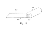
Returning to FIG. 14 , the shaft 322 is an elongated, relatively rigid component defining a proximal section 340 and a distal section 342. The distal section 342 terminates in an electrically conductive tip 344. As described in greater detail below, the tip 344 may be rounded, defining a uniform radius of curvature. In one embodiment, the tip 344 may be shaped like a round ball. The tip 344 may be textured. With the tip being in a rounded configuration, the tip 344 is, similar to the handle 320, indifferent to rotational orientation of the mapping device 312. That is to say, regardless of how a surgeon (not shown) grasps the handle 320 (i.e., the rotational position of the handle 320 relative to the central axis A), a profile of the tip 344 in all directions (e.g., in front of the surgeon's thumb position, behind the surgeon's thumb position, etc.) is always the same so that the tip 344 is readily maneuvered along tissue (not shown) in any direction. To this end, the rounded shape can facilitate a sliding movement of the tip 344 along the tissue.
A preferred feature of the shaft 322 is a malleable or shapeable characteristic. In particular, and with additional reference to FIGS. 15A-15C , the shaft 322 is configured to be transitionable from an initial straight state (FIG. 15A ) to a bent or curved state (FIGS. 15B and 15C ). In this regard, the mapping instrument 312, and in particular the shaft 322, is initially presented to a surgeon (not shown) in the straight state of FIG. 15A , whereby the shaft 322 assumes a straight shape defining the central axis A. In the straight state, the shaft 322 is indifferent to rotational orientation, such that the mapping instrument 312 can be grasped at any rotational position and the tip 344 will be located at an identical position. Further, as previously described, a profile of the tip 344 is also uniform or identical at any rotational position of the mapping instrument 312. Subsequently, depending upon the constraints of a particular mapping procedure, the shaft 322 can be bent relative to the central axis A. Two examples of an applicable bent state or shape are provided in FIGS. 15B and 15C . In a preferred embodiment, the shaft 322 can be bent at any point along a length thereof, and can be formed to include multiple bends or curves. Regardless, the shaft 322 is configured to independently maintain the shape associated with: the selected bent shape. That is to say, the shaft 322 does not require additional components (e.g., pull wires, etc.) to maintain the selected bent shape. Further, the shaft 322 is constructed such that a user can readily re-shape the shaft 322 back to the straight state of FIG. 15A and/or other desired bent configurations. Notably, the shaft 322 is configured to relatively rigidly maintain the selected shape such that when a force is imparted onto the shaft 322 as the tip 344 contacts tissue, the shaft 322 will not overtly deflect from the selected shape.
In one preferred embodiment, the above-described characteristics of the shaft 322 are achieved by forming the shaft 322 to include an elongated electrode body 360 and an electrical insulator covering 362 as shown in FIGS. 14 and 17 . The electrode body 360 defines the proximal section 340 and the distal section 342 of the shaft 322. To tins end, the proximal section 340 of the electrode body 360 is rigidly coupled to the handle 320. The insulator 362 covers a substantial portion of the electrode body 360, preferably leaving the distal section 342 exposed. In particular, the insulator 362 is positioned to encompass an entirety of the electrode body 360 distal the handle 320 and proximal the distal section 342 (and in particular, proximal the tip 344).
In one preferred embodiment, the electrode body 360 is formed of an electrically conductive, malleable material, preferably stainless steel, however other materials such as, for example, nitinol can be used. The insulator 362 is formed of one or more electrically non-conductive materials, e.g., a nonconductive fluoropolymer, and serves to electrically insulate the encompassed portion of the electrode body 360. Multiple layers of electrically non-conductive materials can help prevent the likelihood of forming an electrical short along the length of the electrode body 360 due to a mechanical failure of one of the non-conductive materials. In this regard, the insulator 362 is preferably comprised of two materials having considerably different mechanical properties, e.g., a silicone and a fluoropolymer. In one embodiment, a silicone tubing material is overlaid with a heat shrink fluoropolymer tubing material. Alternatively, the insulator 362 may be one or more non-conductive coatings applied over a portion of the electrode body 360. In addition to being non-conductive, the insulator 362 is preferably flexible and conforms to the electrode body 360 such that the insulator 362 does not impede desired shaping and re-shaping of the electrode body 360 as previously described.
It will be understood that the preferred construction of the shaft 322 to include the elongated electrode body 360 and the insulator 362 is but one available configuration. Alternatively, the shaft 322 can be constructed of an electrode material forming the tip 344, and a rigid or malleable, non-conductive rod or tube rigidly connecting the tip 344 to the handle 320. The non-conductive rod or tube can include one or more metal conductors, such as straight, wire and/or windings for electrically connecting the tip 344 to the diagnostic device 316. The tip 344 may be coated with one or more coatings. Another alternative embodiment includes construction of the shaft 322 to include one or more metal conductors, such as straight wire and/or windings inside a rigid or malleable non-conductive polymer tube. The insulator 362 may cover a portion of the wire or windings.
With respect to the above-described alternative embodiments, connection between the elongated rod or tube and the separate tip 344 can be accomplished in a variety of manners. Once again, the elongated rod or tube can comprise a conductive or non-conductive material(s), such as metal(s) or plastic(s). The elongated rod or tube can be connected to the tip 344 via a variety of coupling techniques, including, for example, welding, laser welding, spin welding, crimping, gluing, soldering and press fitting. Alternatively, the distal end of the elongated rod or tube and the tip 344 can be configured to threadably engage one another and/or mechanical engagement member(s) (e.g., pins, screws, rivets, etc.) can be employed. In another embodiment, the elongated rod or tube is rigidly coupled to the tip 344. In yet another embodiment, the tip 344 can be moveably coupled to the elongated rod or tube, whereby the tip 344 can be moved and/or locked relative to the elongated rod or tube. For example, the tip 344 can be coupled to the elongated rod or tube via one or more joints or hinges. The joints or hinges can be ball joints and/or joints that include a pin. To this end, a pin-type joint can be configured to allow the tip 344 to swivel relative to the elongated rod or tube. Further, the joint(s) can be configured to move and lock into position. In addition, one or more actuators (e.g., knobs, buttons, levers, slides, etc.) can be located on, for example, the handle 320 (FIG. 1 ) for actuating the joint(s). With the above in mind, FIG. 18 illustrates a portion of an alternative embodiment shaft 322′ including a tip 344′ moveably coupled to an elongated rod or tube 363 by a pin 364.
Returning to FIG. 14 , the mapping instrument 312 preferably includes a coupling member 365 for rigidly coupling the shaft 322 to the handle 320. The coupling member 365 can comprise one or more polymers, plastics, and/or rubbers. For example, the coupling member 365 can comprise one or more silicones, acrylics, nylons, polystyrenes, polyvinylchlorides, polycarbonates, polyurethanes, polyethylenes, polypropylenes, polyamides, polyethers, polyesters, polyolefins, polyacrylates, polyisoprenes, fluoropolymers, combinations thereof or the like.
Once the desired shape of the shaft 322 has been achieved, the tip 344 is directed to the tissue target site 74. A grounding electrode (318 in FIG. 14 , but not shown in FIG. 19A ) is placed in contact with the patient. The grounding electrode may comprise a needle electrode and a cable for connection to the diagnostic device 316. Alternatively, a grounding wire may be coupled to diagnostic device 316 and a metal retractor coupled to the patient. For example, a metal sternal retractor used to spread a patient's ribs may be used as a grounding electrode.
If additional lesions are to be assessed, the surgeon again evaluates the target tissue site, and re-forms the shaft 322 accordingly. Notably, the shaft 322 heed not necessarily be bent to perform a tissue mapping/pacing procedure. Instead, the tip 344 can contact the target site tissue 74 with the shaft 322 in the initial straight state. In this regard, because the shaft 322 is straight and the handle 320 (FIG. 14 ) is preferably circumferentially uniform, the mapping instrument 312 does not have a discernable use direction (as compared to the shaft 322 being bent or curved, whereby the curve inherently defines a most appropriate use direction).
In addition to the one exemplary procedure described above, the mapping instrument 312 may be positioned and used, for example, through a thoracotomy, through a sternotomy, percutaneously, transveneously, endoscopically, for example, through a percutaneous port, through a stab wound or puncture, through a small incision, for example, in the chest or in the abdomen, or in combinations thereof. It is also contemplated that the mapping instrument 312 may be used in other ways, for example, in open-chest surgery on a heart in which the sternum is split and the rib cage opened with a retractor.
The mapping system 310, and in particular the mapping instrument 312, described above with respect to FIG. 14 is but one acceptable configuration in accordance with the present invention. That is to say, the system 310 and/or the instrument 312 can assume other forms and/or include additional features while still providing a mapping instrument having a shaft that independently maintains varying shapes associated with a straight state and a bent state, and is indifferent to rotational orientation in the straight state.
For example, the mapping instrument 312 can include one or more surgeon-controlled switches. For example, a switch may be incorporated in or on the mapping instrument 312 or any other location easily and quickly accessed by the surgeon for regulation of the mapping instrument 312 by the surgeon. The switch may be, for example, a hand switch, a foot switch, or a voice-activated switch comprising voice-recognition technologies. One or more switches may be incorporated into the grip portion 324 of the mapping instrument 312. A switch incorporated into the grip portion 324 may be a switch, such as a membrane switch, encompassing the entire circumference of the mapping instrument 312, thereby effectively being indifferent to a rotational orientation when the surgeon grasps the handle. That is to say, due to the cross-sectional shape of the switch, the mapping instrument 312 may be rotated to any position relative to a central axis A, and still be conveniently controlled by the surgeon.
Alternatively, a hand switch connected to the mapping instrument 312, but not incorporated into the mapping instrument 312, may be used. For example, a switch designed to be worn by a surgeon, for example on a surgeon's thumb, may be used to activate and/or deactivate the mapping instrument 312. A switch may be incorporated into a cuff or strap that is placed on or around the thumb or finger of a surgeon. Alternatively, a switch may be designed to fit comfortably in a surgeon's palm.
One or more visual and/or audible signals used to alert a surgeon to the completion or resumption of a procedure, for example, may be incorporated into the mapping instrument 312. For example, a beeping tone or flashing light that increases in frequency as the mapping/pacing period ends or begins may be used. Alternatively or in addition, an indicator light otherwise located on the mapping instrument 312 can be inductively coupled to the diagnostic device 316 and adapted such that when power is being delivered to the mapping instrument 312, the light is visible to the surgeon or other users.
An alternative embodiment, mapping instrument 412 is provided in FIGS. 20A and 20D . The mapping instrument 412 is highly similar to the mapping instrument 312 (FIG. 14 ) previously described, and includes a handle 420, a shaft 422 and wiring 428. The shaft 422 is virtually identical to the shaft 322 (FIG. 14 ) previously described, and forms a tip 444. The shaft 422 is adapted to be bendable from a straight state (FIG. 20A ) to multiple bent states (one of which is illustrated in FIG. 20B ), with die shaft 422 independently maintaining a shape associated with the particular state. Similar to previous embodiments, the wiring 428 electrically couples the diagnostic device 316 (FIG. 14 ) to the shaft 422.
The handle 420 varies from the handle 320 (FIG. 14 ) previously described in that the handle 420 does not define a curved outer surface. Instead, the handle 420 is hexagonal in transverse cross-section. This alternative configuration is, however, indifferent to rotational orientation when grasped by a user, thereby promoting the preferred ease of use feature previously described. Notably, the handle 420 can alternatively be formed to a variety of other symmetrical transverse cross-sectional shapes (e.g., octagonal, etc.).
In yet another alternative embodiment, the mapping system 310 (FIG. 14 ) further includes a controller (not shown) that can also gather and process information from the mapping instrument 312 and/or one or more sensors or sensing elements such as temperature sensors or probes. For example, a temperature sensor coupled to the controller can be located in the distal section 342 (FIG. 14 ) of the mapping instrument 312. The temperature sensor may be a thermocouple element that measures tissue temperature. Alternatively, the temperature sensor may be, for example, one or more thermisters, temperature-sensing liquid crystals, temperature-sensing chemicals, thermal cameras, and/or infrared (IR) fiber optics.
With the above in mind, FIGS. 21A-21C depict a portion of an alternative embodiment mapping device 640, and in particular a distal section 642 thereof. The mapping instrument 640 is highly similar to previous embodiments, and includes a shaft (not shown) terminating at an electrically conductive tip 644. Further, the mapping instrument 640 includes one or more sensors 660, for example, a temperature probe for monitoring tissue temperature. The sensor 660 may be placed at the tip 644. A ring of insulation material 663 may be used to electrically and thermally isolate sensor 660 from the electrically conductive tip 644. The preferred central placement of the sensor 660 at the tip 644 allows the sensor 660 to directly contact a tissue surface in a number of orientations. An alternative embodiment sensor 660 may include an IR optical fiber system, for example, to monitor temperature based on IR. The sensor 660 may be positioned adjacent tip 644 (not shown) or within tip 644 (FIGS. 21A-21C ).
Sensing elements 660 can be coupled to visual and/or audible signals used to alert a surgeon to a variety of procedural conditions. For example, a beeping tone or flashing light that increases in frequency as temperature of the tissue exceeds a predetermined amount can be used.
In one embodiment, diagnostic device 316 can incorporate one or more switches to facilitate regulation of various components of mapping system 310 (FIG. 14 ) by the surgeon. One example of such a switch is a foot pedal. The switch can also be, for example, a hand switch as described above, or a voice-activated switch comprising voice-recognition technologies. The switch can be incorporated in or on one of the surgeon's instruments, such as surgical site retractor, e.g., a sternal or rib retractor, or the mapping instrument 312 (FIG. 14 ), or any other location easily and quickly accessed by the surgeon. The diagnostic device 316 can also include a display or other means of indicating the status of various components to the surgeon, such as a numerical display, gauges; a monitor display or audio feedback.
Finally, a visual and/or audible signal used to alert a surgeon to the completion or resumption of sensing, monitoring, pacing and/or mapping can be incorporated into the controller. For example, a beeping tone or flashing light that increases in frequency as the pacing period ends or begins can be provided.
In yet another embodiment, and with general reference to FIG. 14 , the mapping instrument 312 and/or the diagnostic device 316 can be slaved to a robotic system or a robotic system may be slaved to the mapping instrument 312 and/or the diagnostic device 316.
The handle and shaft of the mapping instrument of the present invention are configured to be indifferent to rotational orientation when initially presented to a surgeon. Subsequently, the surgeon can conveniently shape or bend the shaft so as to provide a shape most conducive to assessing the lesion pattern required by the particular surgical procedure. In this regard, the shaft independently maintains the selected shape throughout the particular mapping/pacing procedure. Subsequently, the shaft can be re-shaped back to a straight configuration, or to any other desired curvature.
In one embodiment, mapping instrument 312 may be used to pace the heart. For example, mapping instrument 312 may be connected to an external temporary pacemaker, e.g., the Medtronic External Temporary Pacemaker model 5388 or the Medtronic 2090/2290 Programmer/Analyzer. Mapping instrument 312 may be used to temporarily pace atrial tissue of the heart and/or ventricular tissue of the heart. For pacing the heart, tip 344 of mapping instrument 312 is put into contact with tissue to be paced. For example, in one embodiment, a textured ball tip electrode 344 is placed into contact with atrial tissue (FIGS. 19A and 19B ).
In one embodiment, a pacing threshold for the mapping instrument 312 for pacing atrial tissue is < 10 mA @ 0.5 ms using the Medtronic 5388 pacemaker. Medtronic's 5388 pacemaker has a maximum output of 20 mA. Ablation lesion testing may be performed by finding the pacing threshold outside the isolated tissue area 74 and then placing the device inside the isolated tissue area 74, as shown in FIGS. 19A and 19B , with 2× the pacing threshold of the non-isolated area. A pacing threshold of 10 mA or less allows the mapping instrument 312 to be used for typical lesion testing after cardiac ablation of atrial tissue 78. Since the Medtronic 5388 device is a current controlled device, pacing threshold for the 5388 temporary pacemaker is the minimum current at which the temporary pacemaker continuously controls pacing of the heart.
The pacing threshold for the mapping instrument 312 for pacing ventricle tissue is < 5V @ 0.5 ms using Medtronic's 2090/2290 Programmer/Analyzer and the resistance at 5V preferably is > 500Ω (5V/500Ω=10 mA). Pacing threshold for the Programmer/Analyzer is the lowest voltage at which continuous capture of the heart occurs. Mapping instrument 312 is used in a unipolar mode (measuring between the tip 344 and a grounding electrode 318, for example a grounding needle placed, for example, in the extrathoracic tissue). Pacing resistance can be measured at 5V while using the Programmer/Analyzer to measure pacing thresholds.
In one embodiment, the mapping instrument 312 can be used in left sided epicardial lead placement procedures. During these procedures, epicardial mapping is useful in identifying the optimal site for epicardial lead placement on the left ventricle. In one embodiment, the mapping instrument 312 is used to pace one or more ventricles and the synchronicity of left ventricular contraction is evaluated, for example, with TEE. Alternatively, tissue Doppler ultrasound may be used to measure contraction patterns and to locate the site where, biventricular pacing could result in the most effective contraction of the left ventricle. While Doppler ultrasound may be may be more effective than TEE, it is not commonly available and may require the patient's chest to be closed in order to provide useful data.
Another approach entails identifying the site of latest left ventricular, electrical activity following a paced right ventricular beat. This electrical site may correlate with the site of latest mechanical activity. Pacing at the site of latest activation can create two contraction wavefronts from electrically opposite sides of the heart while accommodating any unusual conduction pathways. Theoretically, this will create collision of the right and left ventricular wavefronts equidistant from the electrodes on both sides of the ventricle thereby minimizing dysynchrony. The hypothesis for this activation sequence was originally described more than 20 years ago. FIG. 22 illustrates activation patterns 390 and cell-to-cell conduction from right ventricular pacing by an electrode 395 placed in the right ventricle.
The approach of identifying the site of latest left ventricular electrical activity determines the time between a paced event in the right ventricle and the corresponding sensed event in the left ventricle. As the heart is paced in the right ventricle, the electrode tip 344 of mapping instrument 312 is placed into contact of epicardial tissue of the left ventricle and the time at which a depolarization wave is sensed over the left ventricle is noted.
This timeframe is called the “paced depolarization interval” (PDI). Starting at a posterior lateral position, approximately six sites should be measured, see FIG. 23 . The longest time interval or maximum PDI is the point that is electrically farthest from the right ventricular electrode and is generally the site for optimal lead placement.
Paced depolarization intervals will vary among patients. PDI values of normal hearts are usually 100 ms or less, but patients who have congestive heart failure and larger hearts typically have values between 150 ms and 200 ms. In general, the larger the heart, the larger the PDI. In addition, PDIs below 150 ms tend to indicate the lead location is not optimal.
When measuring paced depolarization intervals, it is very important to use a paced beat rather than an intrinsic beat. A CRT system will pace both ventricles and the lead placement site should be chosen in accordance with the way the CRT system functions. Pacing of the right ventricle can be accomplished using either an implanted pacemaker or a programmer/analyzer, for example, the Medtronic 2090/2290 Programmer/Analyzer.
If the patient already has an implanted pacemaker, it is not necessary to remove it or externalize the right ventricular lead prior to mapping for left ventricular lead placement. The pacemaker should be programmed to pace the right ventricle continuously in the unipolar mode. A V pacing pulse may be used to help visualization of the pacing spike on the mapping electrode signal. Mapping instrument 312 should be connected to the programmer or other device to display electrograms (EGMs), which should either be frozen electronically in the programmer or printed on paper for manual measurement. From the EGM, the pacing spike should be seen, as should the depolarization wavefront that passes under the left ventricular mapping electrode. The time between the pacing spike and the depolarization wave on the EGM signal is the PDI. Maximizing the PDI may optimize cardiac resynchronization.
A Programmer/Analyzer, for example, the Medtronic 2090/2290 Programmer/Analyzer, may be used to measure the maximum PDI. If a right ventricular lead is not accessible, the mapping electrode can be connected to either the atrial or ventricular channel of the analyzer. The pacing spike and the depolarization wavefront should both be visible on the data strip, see FIG. 24 . During this measurement, the right ventricular lead should be pacing the heart with the implanted pacemaker in the unipolar mode. The time can then be measured between the pacing spike and the left ventricular deflection.
If the right ventricular lead is accessible, both leads can be connected to the analyzer. The right ventricular lead is connected to the ventricular channel and the mapping instrument 312 is connected to the atrial channel. The analyzer can then pace the right ventricular lead, sense the left ventricular mapping electrode, and display the time between the paced and sensed events on the screen. In this case, the right ventricular (RV) and left ventricular (LV) EGMs shown in FIG. 25 will both be visible. The strips can be frozen electronically in the analyzer and the maximum EDI measured with calipers, or they can be printed on paper for manual measurement.
In another embodiment, the electrosurgical instrument 12 includes a mode switch (not shown). For example, a surgeon-controlled mode switch may be incorporated in or on the electrosurgical instrument 12 or any other location easily and quickly accessed by a surgeon for switching between an ablation mode, a mapping mode and/or a pacing mode. The switch may be, for example, a hand switch, a foot switch, or a voice-activated switch comprising voice-recognition technologies. A mode switch would allow the electrosurgical instrument 12 to be used as both an ablation tool and a mapping/pacing tool. For example, an energy source may be electrically connected to electrosurgical instrument 12, wherein the energy source comprises ablation energy for creating tissue lesions and stimulation energy for pacing the heart. A switch coupled to the energy source may be configured to control delivery of ablation energy and stimulation energy from the energy source to electrosurgical instrument 12. The delivery of ablation energy to electrosurgical instrument 12 may be stopped when the delivery of stimulation energy to electrosurgical instrument 12 is started and the delivery of stimulation energy to electrosurgical instrument 12 may be stopped when the delivery of ablation energy to electrosurgical instrument 12 is started. The switch may also be coupled to a source of conductive fluid. In this case, the switch may be configured to control delivery of fluid from a source of conductive fluid to the internal lumen of the instrument. For example, the delivery of fluid to the internal lumen of the instrument may be stopped when the delivery of ablation energy to the tip of the instrument is stopped and the delivery of fluid to the internal lumen of the instrument may be started when the delivery of ablation energy to the tip of the instrument is started.
In yet another alternative embodiment, the electrosurgical instrument 12 includes a visual and/or audible signaling device (not shown) used to alert a surgeon to any change in the mode of the device. For example, a beeping tone or flashing light can be used to alert the surgeon that the electrosurgical instrument 12 is in an ablation mode or has changed from a mapping/pacing mode to an ablation mode. For example, one or more indicator lights located on the instrument can indicate the delivery of ablation energy and/or stimulation energy for pacing heart tissue.
Although the invention has been described above in connection with particular embodiments and examples, it will be appreciated by those skilled in the art that the invention is not necessarily so limited, and that numerous other embodiments, examples, uses, modifications and departures from the embodiments, examples and uses are intended to be encompassed by the claims attached hereto. The entire disclosure of each patent and publication cited herein is incorporated by reference, as if each such patent or publication were individually incorporated by reference herein.
Claims (11)
1. A method of performing an ablation procedure, the method comprising:
providing a first instrument including an elongated shaft and a handle, the shaft defining a proximal section rigidly coupled to the handle, a distal section forming an electrically conductive tip;
positioning the tip of the first instrument through a patient's chest;
applying ablation energy to the tip of the first instrument while contacting cardiac tissue;
creating an ablation lesion to isolate an area of cardiac tissue;
providing a second instrument including an elongated shaft and a handle, the shaft defining a proximal section rigidly coupled to the handle, a distal section forming an electrically conductive tip;
positioning the tip of the second instrument through a patient's chest; and
applying stimulation energy to the tip of the second instrument while contacting the area of isolated cardiac tissue to assess transmurality of the ablation lesion.
2. The method of claim 1 , wherein the first instrument further comprises an internal lumen extending from the proximal section of the shaft and in fluid communication with at least one passage formed in the distal section of the shaft.
3. The method of claim 2 , further comprising:
dispensing conductive fluid from the internal lumen of the shaft via the at least one passage.
4. The method of claim 1 , wherein the ablation energy is radiofrequency energy.
5. The method of claim 1 , wherein the step of applying ablation energy to the tip of the first instrument includes dragging the tip of the first instrument along the cardiac tissue.
6. A method of performing an ablation procedure, the method comprising:
providing an instrument including an elongated shaft and a handle, the shaft defining a proximal section rigidly coupled to the handle, a distal section forming an electrically conductive tip;
positioning the tip through a patient's chest;
applying ablation energy to the tip while contacting cardiac tissue;
creating an ablation lesion to isolate an area of cardiac tissue;
stopping the application of ablation energy to the tip;
repositioning the tip; and
applying stimulation energy to the tip while contacting the area of isolated cardiac tissue to assess transmurality of the ablation lesion.
7. The method of claim 6 , wherein the instrument further comprises an internal lumen extending from the proximal section of the shaft and in fluid communication with at least one passage formed in the distal section of the shaft.
8. The method of claim 7 , further comprising:
dispensing conductive fluid from the internal lumen of the shaft via the at least one passage while applying ablation energy to the tip.
9. The method of claim 6 , wherein the ablation energy is radio frequency energy.
10. The method of claim 6 , wherein the step of repositioning the tip includes contacting the tip against tissue entirely within the area of isolated tissue, and the step of applying stimulation energy to the tip occurs after the step of repositioning the tip.
11. A method of performing an ablation procedure, the method comprising:
providing an instrument including an elongated shaft and a handle, the shaft defining a proximal section rigidly coupled to the handle, a distal section forming an electrically conductive tip;
advancing the tip of the instrument through a patient's chest and into the patient's coronary sinus;
positioning the tip of the instrument in the patient's coronary sinus between an existing lesion encircling at least a portion of the patient's pulmonary veins and the annulus of the patient's mitral valve;
applying ablation energy to the tip of the instrument while the tip is positioned in the coronary sinus; and
creating an ablation lesion in an area of cardiac tissue surrounding the tip.
Priority Applications (1)
| Application Number | Priority Date | Filing Date | Title |
|---|---|---|---|
| US12/480,926 US8623010B2 (en) | 2002-01-25 | 2009-06-09 | Cardiac mapping instrument with shapeable electrode |
Applications Claiming Priority (3)
| Application Number | Priority Date | Filing Date | Title |
|---|---|---|---|
| US10/056,807 US7967816B2 (en) | 2002-01-25 | 2002-01-25 | Fluid-assisted electrosurgical instrument with shapeable electrode |
| US10/853,594 US20040267326A1 (en) | 2002-01-25 | 2004-05-25 | Cardiac mapping instrument with shapeable electrode |
| US12/480,926 US8623010B2 (en) | 2002-01-25 | 2009-06-09 | Cardiac mapping instrument with shapeable electrode |
Related Parent Applications (1)
| Application Number | Title | Priority Date | Filing Date |
|---|---|---|---|
| US10/853,594 Division US20040267326A1 (en) | 2002-01-25 | 2004-05-25 | Cardiac mapping instrument with shapeable electrode |
Publications (2)
| Publication Number | Publication Date |
|---|---|
| US20090326527A1 US20090326527A1 (en) | 2009-12-31 |
| US8623010B2 true US8623010B2 (en) | 2014-01-07 |
Family
ID=27609330
Family Applications (4)
| Application Number | Title | Priority Date | Filing Date |
|---|---|---|---|
| US10/056,807 Expired - Fee Related US7967816B2 (en) | 2002-01-25 | 2002-01-25 | Fluid-assisted electrosurgical instrument with shapeable electrode |
| US10/853,594 Abandoned US20040267326A1 (en) | 2002-01-25 | 2004-05-25 | Cardiac mapping instrument with shapeable electrode |
| US11/586,112 Abandoned US20070043397A1 (en) | 2002-01-25 | 2006-10-25 | Cardiac mapping instrument with shapeable electrode |
| US12/480,926 Active 2025-06-25 US8623010B2 (en) | 2002-01-25 | 2009-06-09 | Cardiac mapping instrument with shapeable electrode |
Family Applications Before (3)
| Application Number | Title | Priority Date | Filing Date |
|---|---|---|---|
| US10/056,807 Expired - Fee Related US7967816B2 (en) | 2002-01-25 | 2002-01-25 | Fluid-assisted electrosurgical instrument with shapeable electrode |
| US10/853,594 Abandoned US20040267326A1 (en) | 2002-01-25 | 2004-05-25 | Cardiac mapping instrument with shapeable electrode |
| US11/586,112 Abandoned US20070043397A1 (en) | 2002-01-25 | 2006-10-25 | Cardiac mapping instrument with shapeable electrode |
Country Status (5)
| Country | Link |
|---|---|
| US (4) | US7967816B2 (en) |
| EP (1) | EP1476093B1 (en) |
| AT (1) | ATE507792T1 (en) |
| DE (1) | DE60336983D1 (en) |
| WO (1) | WO2003063718A1 (en) |
Cited By (6)
| Publication number | Priority date | Publication date | Assignee | Title |
|---|---|---|---|---|
| US20150157405A1 (en) * | 2013-12-05 | 2015-06-11 | Biosense Webster (Israel) Ltd. | Needle catheter utilizing optical spectroscopy for tumor identification and ablation |
| US10034707B2 (en) | 2014-12-30 | 2018-07-31 | Biosense Webster (Israel) Ltd. | Catheter with irrigated tip electrode with porous substrate and high density surface micro-electrodes |
| WO2019148127A1 (en) | 2018-01-29 | 2019-08-01 | Medtronic, Inc. | Cardiac surgical instrument and connector with built-in electrogram (egm) filtering circuitry |
| US11040208B1 (en) | 2019-12-17 | 2021-06-22 | Biosense Webster (Israel) Ltd. | Distributed cardiac pacing system |
| US11331140B2 (en) | 2016-05-19 | 2022-05-17 | Aqua Heart, Inc. | Heated vapor ablation systems and methods for treating cardiac conditions |
| US11589920B2 (en) | 2008-10-06 | 2023-02-28 | Santa Anna Tech Llc | Catheter with a double balloon structure to generate and apply an ablative zone to tissue |
Families Citing this family (189)
| Publication number | Priority date | Publication date | Assignee | Title |
|---|---|---|---|---|
| US6409722B1 (en) | 1998-07-07 | 2002-06-25 | Medtronic, Inc. | Apparatus and method for creating, maintaining, and controlling a virtual electrode used for the ablation of tissue |
| US5897553A (en) | 1995-11-02 | 1999-04-27 | Medtronic, Inc. | Ball point fluid-assisted electrocautery device |
| US6096037A (en) | 1997-07-29 | 2000-08-01 | Medtronic, Inc. | Tissue sealing electrosurgery device and methods of sealing tissue |
| US6537248B2 (en) | 1998-07-07 | 2003-03-25 | Medtronic, Inc. | Helical needle apparatus for creating a virtual electrode used for the ablation of tissue |
| US6706039B2 (en) | 1998-07-07 | 2004-03-16 | Medtronic, Inc. | Method and apparatus for creating a bi-polar virtual electrode used for the ablation of tissue |
| US8241274B2 (en) | 2000-01-19 | 2012-08-14 | Medtronic, Inc. | Method for guiding a medical device |
| US7706882B2 (en) | 2000-01-19 | 2010-04-27 | Medtronic, Inc. | Methods of using high intensity focused ultrasound to form an ablated tissue area |
| US8221402B2 (en) | 2000-01-19 | 2012-07-17 | Medtronic, Inc. | Method for guiding a medical device |
| WO2003024349A1 (en) | 2001-09-05 | 2003-03-27 | Tissuelink Medical, Inc. | Fluid-assisted medical devices, systems and methods |
| US7811282B2 (en) | 2000-03-06 | 2010-10-12 | Salient Surgical Technologies, Inc. | Fluid-assisted electrosurgical devices, electrosurgical unit with pump and methods of use thereof |
| US8048070B2 (en) | 2000-03-06 | 2011-11-01 | Salient Surgical Technologies, Inc. | Fluid-assisted medical devices, systems and methods |
| EP1278471B1 (en) | 2000-04-27 | 2005-06-15 | Medtronic, Inc. | Vibration sensitive ablation apparatus |
| US6514250B1 (en) | 2000-04-27 | 2003-02-04 | Medtronic, Inc. | Suction stabilized epicardial ablation devices |
| US6926669B1 (en) | 2000-10-10 | 2005-08-09 | Medtronic, Inc. | Heart wall ablation/mapping catheter and method |
| US20040138621A1 (en) | 2003-01-14 | 2004-07-15 | Jahns Scott E. | Devices and methods for interstitial injection of biologic agents into tissue |
| US7740623B2 (en) | 2001-01-13 | 2010-06-22 | Medtronic, Inc. | Devices and methods for interstitial injection of biologic agents into tissue |
| US6807968B2 (en) | 2001-04-26 | 2004-10-26 | Medtronic, Inc. | Method and system for treatment of atrial tachyarrhythmias |
| US6663627B2 (en) | 2001-04-26 | 2003-12-16 | Medtronic, Inc. | Ablation system and method of use |
| US6699240B2 (en) | 2001-04-26 | 2004-03-02 | Medtronic, Inc. | Method and apparatus for tissue ablation |
| US7959626B2 (en) | 2001-04-26 | 2011-06-14 | Medtronic, Inc. | Transmural ablation systems and methods |
| US20030130713A1 (en) | 2001-05-21 | 2003-07-10 | Stewart Mark T. | Trans-septal catheter with retention mechanism |
| US7785324B2 (en) | 2005-02-25 | 2010-08-31 | Endoscopic Technologies, Inc. (Estech) | Clamp based lesion formation apparatus and methods configured to protect non-target tissue |
| US7753908B2 (en) | 2002-02-19 | 2010-07-13 | Endoscopic Technologies, Inc. (Estech) | Apparatus for securing an electrophysiology probe to a clamp |
| US7967816B2 (en) * | 2002-01-25 | 2011-06-28 | Medtronic, Inc. | Fluid-assisted electrosurgical instrument with shapeable electrode |
| US20080275439A1 (en) * | 2002-01-25 | 2008-11-06 | David Francischelli | Cardiac ablation and electrical interface system and instrument |
| US6932816B2 (en) * | 2002-02-19 | 2005-08-23 | Boston Scientific Scimed, Inc. | Apparatus for converting a clamp into an electrophysiology device |
| US7653438B2 (en) | 2002-04-08 | 2010-01-26 | Ardian, Inc. | Methods and apparatus for renal neuromodulation |
| US8774913B2 (en) | 2002-04-08 | 2014-07-08 | Medtronic Ardian Luxembourg S.A.R.L. | Methods and apparatus for intravasculary-induced neuromodulation |
| US7294143B2 (en) | 2002-05-16 | 2007-11-13 | Medtronic, Inc. | Device and method for ablation of cardiac tissue |
| US7118566B2 (en) | 2002-05-16 | 2006-10-10 | Medtronic, Inc. | Device and method for needle-less interstitial injection of fluid for ablation of cardiac tissue |
| US6978184B1 (en) * | 2002-07-29 | 2005-12-20 | Marcus Frank I | Optimization method for cardiac resynchronization therapy |
| US7083620B2 (en) | 2002-10-30 | 2006-08-01 | Medtronic, Inc. | Electrosurgical hemostat |
| US7497857B2 (en) | 2003-04-29 | 2009-03-03 | Medtronic, Inc. | Endocardial dispersive electrode for use with a monopolar RF ablation pen |
| DE10323566B4 (en) * | 2003-05-26 | 2006-03-23 | Fehling Ag | Instrument for unipolar ablation of cardiac tissue |
| US7960935B2 (en) | 2003-07-08 | 2011-06-14 | The Board Of Regents Of The University Of Nebraska | Robotic devices with agent delivery components and related methods |
| US8002770B2 (en) | 2003-12-02 | 2011-08-23 | Endoscopic Technologies, Inc. (Estech) | Clamp based methods and apparatus for forming lesions in tissue and confirming whether a therapeutic lesion has been formed |
| US8333764B2 (en) | 2004-05-12 | 2012-12-18 | Medtronic, Inc. | Device and method for determining tissue thickness and creating cardiac ablation lesions |
| ATE399579T1 (en) | 2004-05-14 | 2008-07-15 | Medtronic Inc | SYSTEM FOR USING HIGH-INTENSITY FOCUSED ULTRASOUND TO FORM AN ABLATED AREA OF TISSUE |
| WO2005120375A2 (en) | 2004-06-02 | 2005-12-22 | Medtronic, Inc. | Loop ablation apparatus and method |
| EP1750608B1 (en) | 2004-06-02 | 2012-10-03 | Medtronic, Inc. | Ablation device with jaws |
| WO2005120377A1 (en) | 2004-06-02 | 2005-12-22 | Medtronic, Inc. | Clamping ablation tool |
| DE602005021096D1 (en) | 2004-06-02 | 2010-06-17 | Medtronic Inc | COMPOUND BIPOLAR ABLATION DEVICE |
| US8926635B2 (en) * | 2004-06-18 | 2015-01-06 | Medtronic, Inc. | Methods and devices for occlusion of an atrial appendage |
| US8663245B2 (en) | 2004-06-18 | 2014-03-04 | Medtronic, Inc. | Device for occlusion of a left atrial appendage |
| US8409219B2 (en) | 2004-06-18 | 2013-04-02 | Medtronic, Inc. | Method and system for placement of electrical lead inside heart |
| US7556627B2 (en) * | 2004-09-13 | 2009-07-07 | Ethicon Endo-Surgery, Inc. | Mucosal ablation device |
| DE202004020275U1 (en) * | 2004-12-30 | 2005-02-24 | Schäfer, Olaf | Laser dental instrument with dual different wavelength laser modules has a switch between control electronics and the modules, which serves to select one or other of the modules |
| US7727231B2 (en) | 2005-01-08 | 2010-06-01 | Boston Scientific Scimed, Inc. | Apparatus and methods for forming lesions in tissue and applying stimulation energy to tissue in which lesions are formed |
| CA2541108A1 (en) * | 2005-03-31 | 2006-09-30 | Sherwood Services Ag | Electrosurgical cannulas, systems and method |
| US7962208B2 (en) | 2005-04-25 | 2011-06-14 | Cardiac Pacemakers, Inc. | Method and apparatus for pacing during revascularization |
| US8945151B2 (en) | 2005-07-13 | 2015-02-03 | Atricure, Inc. | Surgical clip applicator and apparatus including the same |
| CA2638029A1 (en) * | 2006-01-27 | 2007-08-09 | Medtronic, Inc. | Ablation device and system for guiding said ablation device into a patient's body |
| AU2007210011A1 (en) | 2006-01-27 | 2007-08-09 | Medtronic, Inc. | Device and system for surgical dissection and or guidance of other medical devices into body |
| WO2007140331A2 (en) | 2006-05-25 | 2007-12-06 | Medtronic, Inc. | Methods of using high intensity focused ultrasound to form an ablated tissue area containing a plurality of lesions |
| CA3068216C (en) | 2006-06-22 | 2023-03-07 | Board Of Regents Of The University Of Nebraska | Magnetically coupleable robotic devices and related methods |
| US8679096B2 (en) | 2007-06-21 | 2014-03-25 | Board Of Regents Of The University Of Nebraska | Multifunctional operational component for robotic devices |
| US9579088B2 (en) | 2007-02-20 | 2017-02-28 | Board Of Regents Of The University Of Nebraska | Methods, systems, and devices for surgical visualization and device manipulation |
| US20080161705A1 (en) * | 2006-12-29 | 2008-07-03 | Podmore Jonathan L | Devices and methods for ablating near AV groove |
| US10166066B2 (en) | 2007-03-13 | 2019-01-01 | University Of Virginia Patent Foundation | Epicardial ablation catheter and method of use |
| EP2134253B1 (en) | 2007-03-19 | 2022-01-26 | University Of Virginia Patent Foundation | Access needle pressure sensor device |
| US9468396B2 (en) | 2007-03-19 | 2016-10-18 | University Of Virginia Patent Foundation | Systems and methods for determining location of an access needle in a subject |
| US11058354B2 (en) | 2007-03-19 | 2021-07-13 | University Of Virginia Patent Foundation | Access needle with direct visualization and related methods |
| US9211405B2 (en) | 2007-03-22 | 2015-12-15 | University Of Virginia Patent Foundation | Electrode catheter for ablation purposes and related method thereof |
| US8945114B2 (en) * | 2007-04-26 | 2015-02-03 | Medtronic, Inc. | Fluid sensor for ablation therapy |
| US8123745B2 (en) * | 2007-06-29 | 2012-02-28 | Biosense Webster, Inc. | Ablation catheter with optically transparent, electrically conductive tip |
| EP3078344B1 (en) | 2007-07-12 | 2020-02-26 | Board of Regents of the University of Nebraska | Actuation in robotic devices |
| JP2010536435A (en) * | 2007-08-15 | 2010-12-02 | ボード オブ リージェンツ オブ ザ ユニバーシティ オブ ネブラスカ | Medical inflation, attachment and delivery devices and associated methods |
| CA2695619C (en) | 2007-08-15 | 2015-11-24 | Board Of Regents Of The University Of Nebraska | Modular and cooperative medical devices and related systems and methods |
| US20090082827A1 (en) * | 2007-09-26 | 2009-03-26 | Cardiac Pacemakers, Inc. | Hinged anchors for wireless pacing electrodes |
| US20100298759A1 (en) * | 2007-10-11 | 2010-11-25 | Region Hovedstaden V/Herlev Hospital | electroporation device for improved electrical field control |
| US8145306B2 (en) | 2007-10-15 | 2012-03-27 | Lessmeier Timothy J | Method for optimizing CRT therapy |
| WO2009062105A2 (en) * | 2007-11-08 | 2009-05-14 | Angiodynamics, Inc. | Device and method for providing power to lighting elements for use as a visual indicator in a medical probe |
| US20100241185A1 (en) | 2007-11-09 | 2010-09-23 | University Of Virginia Patent Foundation | Steerable epicardial pacing catheter system placed via the subxiphoid process |
| EP2227174B1 (en) * | 2007-12-28 | 2019-05-01 | Salient Surgical Technologies, Inc. | Fluid-assisted electrosurgical device |
| US20090318943A1 (en) * | 2008-06-19 | 2009-12-24 | Tracee Eidenschink | Vascular intervention catheters with pacing electrodes |
| US9037235B2 (en) * | 2008-06-19 | 2015-05-19 | Cardiac Pacemakers, Inc. | Pacing catheter with expandable distal end |
| US8639357B2 (en) | 2008-06-19 | 2014-01-28 | Cardiac Pacemakers, Inc. | Pacing catheter with stent electrode |
| US8244352B2 (en) * | 2008-06-19 | 2012-08-14 | Cardiac Pacemakers, Inc. | Pacing catheter releasing conductive liquid |
| US8457738B2 (en) | 2008-06-19 | 2013-06-04 | Cardiac Pacemakers, Inc. | Pacing catheter for access to multiple vessels |
| US9409012B2 (en) | 2008-06-19 | 2016-08-09 | Cardiac Pacemakers, Inc. | Pacemaker integrated with vascular intervention catheter |
| EP2147697A1 (en) * | 2008-07-21 | 2010-01-27 | Centre National De La Recherche Scientifique-CNRS | Process and device for applying electric fields into conductive material |
| EP2156860A1 (en) * | 2008-08-20 | 2010-02-24 | Centre National De La Recherche Scientifique-CNRS | Method for producing insulated electrodes for applying electric fields into conductive material |
| WO2010057067A2 (en) * | 2008-11-17 | 2010-05-20 | Sunnybrook Health Sciences Centre | Focused ultrasound system |
| US8355799B2 (en) * | 2008-12-12 | 2013-01-15 | Arthrocare Corporation | Systems and methods for limiting joint temperature |
| US9254168B2 (en) | 2009-02-02 | 2016-02-09 | Medtronic Advanced Energy Llc | Electro-thermotherapy of tissue using penetrating microelectrode array |
| EP2398416B1 (en) | 2009-02-23 | 2015-10-28 | Medtronic Advanced Energy LLC | Fluid-assisted electrosurgical device |
| EP2432412A2 (en) * | 2009-05-20 | 2012-03-28 | Herlev Hospital | Electroporation device with improved tip and electrode support |
| CN102497832B (en) | 2009-09-08 | 2015-09-09 | 显著外科技术公司 | For case assembly and the using method thereof of electro-surgical device, electrosurgical unit |
| US9642534B2 (en) | 2009-09-11 | 2017-05-09 | University Of Virginia Patent Foundation | Systems and methods for determining location of an access needle in a subject |
| CA2784883A1 (en) | 2009-12-17 | 2011-06-23 | Board Of Regents Of The University Of Nebraska | Modular and cooperative medical devices and related systems and methods |
| EP2523620B1 (en) * | 2010-01-15 | 2019-06-19 | Medtronic Advanced Energy LLC | Electrosurgical device |
| CA2790328C (en) | 2010-02-18 | 2017-04-18 | University Of Virginia Patent Foundation | System, method, and computer program product for simulating epicardial electrophysiology procedures |
| US20110208180A1 (en) * | 2010-02-25 | 2011-08-25 | Vivant Medical, Inc. | System and Method for Monitoring Ablation Size |
| US9592090B2 (en) | 2010-03-11 | 2017-03-14 | Medtronic Advanced Energy Llc | Bipolar electrosurgical cutter with position insensitive return electrode contact |
| EP2547276B1 (en) * | 2010-03-15 | 2016-08-31 | Boston Scientific Scimed, Inc. | Ablation catheter with isolated temperature sensing tip |
| EP2563256B1 (en) * | 2010-04-26 | 2019-08-28 | Medtronic Holding Company Sàrl | Electrosurgical device |
| US20110295249A1 (en) * | 2010-05-28 | 2011-12-01 | Salient Surgical Technologies, Inc. | Fluid-Assisted Electrosurgical Devices, and Methods of Manufacture Thereof |
| US20110319478A1 (en) | 2010-06-04 | 2011-12-29 | Medtronic, Inc. | Compositions to Treat Cardiac Pacing Conditions |
| US9138289B2 (en) | 2010-06-28 | 2015-09-22 | Medtronic Advanced Energy Llc | Electrode sheath for electrosurgical device |
| US8906012B2 (en) | 2010-06-30 | 2014-12-09 | Medtronic Advanced Energy Llc | Electrosurgical devices with wire electrode |
| US8920417B2 (en) | 2010-06-30 | 2014-12-30 | Medtronic Advanced Energy Llc | Electrosurgical devices and methods of use thereof |
| US8968267B2 (en) | 2010-08-06 | 2015-03-03 | Board Of Regents Of The University Of Nebraska | Methods and systems for handling or delivering materials for natural orifice surgery |
| US8649851B2 (en) * | 2010-09-15 | 2014-02-11 | Pacesetter, Inc. | Method and system for quantitative measure of current of injury during lead fixation |
| TWI556849B (en) | 2010-10-21 | 2016-11-11 | 美敦力阿福盧森堡公司 | Catheter apparatus for renal neuromodulation |
| CN202665687U (en) | 2010-10-25 | 2013-01-16 | 美敦力Af卢森堡有限责任公司 | Catheter device used for treatment of human patient via renal denervation |
| US9023040B2 (en) | 2010-10-26 | 2015-05-05 | Medtronic Advanced Energy Llc | Electrosurgical cutting devices |
| US8603089B2 (en) | 2011-01-19 | 2013-12-10 | Covidien Lp | Surgical instrument including inductively coupled accessory |
| US9427281B2 (en) | 2011-03-11 | 2016-08-30 | Medtronic Advanced Energy Llc | Bronchoscope-compatible catheter provided with electrosurgical device |
| EP3977951B1 (en) | 2011-06-10 | 2023-11-08 | Board of Regents of the University of Nebraska | Surgical end effector |
| EP2732344B1 (en) | 2011-07-11 | 2019-06-05 | Board of Regents of the University of Nebraska | Robotic surgical system |
| EP2757933B1 (en) | 2011-09-22 | 2019-02-06 | The George Washington University | Systems for visualizing ablated tissue |
| CN104066368B (en) | 2011-09-22 | 2017-02-22 | 乔治华盛顿大学 | Systems and methods for visualizing ablated tissue |
| US9161805B2 (en) | 2011-09-28 | 2015-10-20 | Medtronic, Inc. | Surgical devices and mechanisms |
| US9750565B2 (en) | 2011-09-30 | 2017-09-05 | Medtronic Advanced Energy Llc | Electrosurgical balloons |
| US8870864B2 (en) | 2011-10-28 | 2014-10-28 | Medtronic Advanced Energy Llc | Single instrument electrosurgery apparatus and its method of use |
| US20130131500A1 (en) * | 2011-11-18 | 2013-05-23 | Covidien Lp | In-situ proximity recognition apparatus |
| US9131980B2 (en) | 2011-12-19 | 2015-09-15 | Medtronic Advanced Energy Llc | Electrosurgical devices |
| WO2013106569A2 (en) | 2012-01-10 | 2013-07-18 | Board Of Regents Of The University Of Nebraska | Methods, systems, and devices for surgical access and insertion |
| EP4357083A2 (en) | 2012-05-01 | 2024-04-24 | Board of Regents of the University of Nebraska | Single site robotic device and related systems and methods |
| CN107157575B (en) | 2012-05-11 | 2020-03-06 | 美敦力Af卢森堡有限责任公司 | Catheter apparatus |
| US9226792B2 (en) | 2012-06-12 | 2016-01-05 | Medtronic Advanced Energy Llc | Debridement device and method |
| EP3680071B1 (en) | 2012-06-22 | 2021-09-01 | Board of Regents of the University of Nebraska | Local control robotic surgical devices |
| US9770305B2 (en) | 2012-08-08 | 2017-09-26 | Board Of Regents Of The University Of Nebraska | Robotic surgical devices, systems, and related methods |
| EP2882331A4 (en) | 2012-08-08 | 2016-03-23 | Univ Nebraska | Robotic surgical devices, systems, and related methods |
| CA2883231C (en) | 2012-08-28 | 2022-12-06 | Instruventional Inc. | Adjustable electrosurgical pencil |
| US11234760B2 (en) | 2012-10-05 | 2022-02-01 | Medtronic Advanced Energy Llc | Electrosurgical device for cutting and removing tissue |
| US9044575B2 (en) | 2012-10-22 | 2015-06-02 | Medtronic Adrian Luxembourg S.a.r.l. | Catheters with enhanced flexibility and associated devices, systems, and methods |
| US10543127B2 (en) | 2013-02-20 | 2020-01-28 | Cytrellis Biosystems, Inc. | Methods and devices for skin tightening |
| US10195467B2 (en) | 2013-02-21 | 2019-02-05 | Boston Scientific Scimed, Inc. | Ablation catheter system with wireless radio frequency temperature sensor |
| US10028764B2 (en) | 2013-02-21 | 2018-07-24 | Boston Scientific Scimed, Inc. | Ablation catheter with wireless temperature sensor |
| US9877707B2 (en) | 2013-03-07 | 2018-01-30 | Kyphon SÀRL | Systems and methods for track coagulation |
| US9888966B2 (en) | 2013-03-14 | 2018-02-13 | Board Of Regents Of The University Of Nebraska | Methods, systems, and devices relating to force control surgical systems |
| US9743987B2 (en) | 2013-03-14 | 2017-08-29 | Board Of Regents Of The University Of Nebraska | Methods, systems, and devices relating to robotic surgical devices, end effectors, and controllers |
| US10667883B2 (en) | 2013-03-15 | 2020-06-02 | Virtual Incision Corporation | Robotic surgical devices, systems, and related methods |
| US9775665B2 (en) | 2013-03-15 | 2017-10-03 | Alan G Ellman | Fixed position RF electrode |
| EP2967397B1 (en) | 2013-03-15 | 2023-07-12 | Medtronic Holding Company Sàrl | Electrosurgical mapping tools |
| WO2014189794A1 (en) | 2013-05-18 | 2014-11-27 | Medtronic Ardian Luxembourg S.A.R.L. | Neuromodulation catheters with shafts for enhanced flexibility and control and associated devices, systems, and methods |
| JP6479790B2 (en) | 2013-07-17 | 2019-03-06 | ボード オブ リージェンツ オブ ザ ユニバーシティ オブ ネブラスカ | Robotic surgical device, system and related methods |
| CA2827695C (en) | 2013-09-20 | 2021-02-16 | Leonard Ineson | Adjustable electrosurgical pencil |
| US10631914B2 (en) | 2013-09-30 | 2020-04-28 | Covidien Lp | Bipolar electrosurgical instrument with movable electrode and related systems and methods |
| JP2017500550A (en) | 2013-11-20 | 2017-01-05 | ザ・ジョージ・ワシントン・ユニバーシティThe George Washingtonuniversity | System and method for hyperspectral analysis of cardiac tissue |
| EP3082897A4 (en) | 2013-12-19 | 2017-07-26 | Cytrellis Biosystems, Inc. | Methods and devices for manipulating subdermal fat |
| US10314647B2 (en) | 2013-12-23 | 2019-06-11 | Medtronic Advanced Energy Llc | Electrosurgical cutting instrument |
| WO2015113034A1 (en) | 2014-01-27 | 2015-07-30 | Medtronic Ardian Luxembourg S.A.R.L. | Neuromodulation catheters having jacketed neuromodulation elements and related devices, systems, and methods |
| US10813686B2 (en) | 2014-02-26 | 2020-10-27 | Medtronic Advanced Energy Llc | Electrosurgical cutting instrument |
| WO2015153815A1 (en) * | 2014-04-01 | 2015-10-08 | Gregory Brucker | Temperature-responsive irrigated ablation electrode with reduced coolant flow and related methods for making and using |
| JP2017513600A (en) | 2014-04-24 | 2017-06-01 | メドトロニック アーディアン ルクセンブルク ソシエテ ア レスポンサビリテ リミテ | Nerve adjustment catheter with braided shaft and related systems and methods |
| US9974599B2 (en) | 2014-08-15 | 2018-05-22 | Medtronic Ps Medical, Inc. | Multipurpose electrosurgical device |
| CA2961213A1 (en) | 2014-09-12 | 2016-03-17 | Board Of Regents Of The University Of Nebraska | Quick-release end effectors and related systems and methods |
| US9956029B2 (en) | 2014-10-31 | 2018-05-01 | Medtronic Advanced Energy Llc | Telescoping device with saline irrigation line |
| JP2017537681A (en) | 2014-11-03 | 2017-12-21 | ザ・ジョージ・ワシントン・ユニバーシティThe George Washingtonuniversity | Damage evaluation system and method |
| EP3215001A4 (en) | 2014-11-03 | 2018-04-04 | Luxcath, LLC | Systems and methods for assessment of contact quality |
| EP4286104A3 (en) | 2014-11-11 | 2024-02-14 | Board of Regents of the University of Nebraska | Robotic device with compact joint design and related systems and methods |
| WO2016077759A1 (en) * | 2014-11-14 | 2016-05-19 | Cytrellis Biosystems, Inc. | Devices and methods for ablation of the skin |
| US9956026B2 (en) * | 2015-02-12 | 2018-05-01 | Virginia Rost | Blood vessel cauterizing tool assembly |
| WO2016134156A1 (en) | 2015-02-18 | 2016-08-25 | Medtronic Xomed, Inc. | Rf energy enabled tissue debridement device |
| US10188456B2 (en) | 2015-02-18 | 2019-01-29 | Medtronic Xomed, Inc. | Electrode assembly for RF energy enabled tissue debridement device |
| US10376302B2 (en) | 2015-02-18 | 2019-08-13 | Medtronic Xomed, Inc. | Rotating electrical connector for RF energy enabled tissue debridement device |
| CA2984207A1 (en) | 2015-05-12 | 2016-11-17 | National University Of Ireland Galway | Devices for therapeutic nasal neuromodulation and associated methods and systems |
| US10779904B2 (en) | 2015-07-19 | 2020-09-22 | 460Medical, Inc. | Systems and methods for lesion formation and assessment |
| JP6961146B2 (en) | 2015-08-03 | 2021-11-05 | バーチャル インシジョン コーポレイションVirtual Incision Corporation | Robotic surgical devices, systems and related methods |
| US11389227B2 (en) | 2015-08-20 | 2022-07-19 | Medtronic Advanced Energy Llc | Electrosurgical device with multivariate control |
| US11051875B2 (en) | 2015-08-24 | 2021-07-06 | Medtronic Advanced Energy Llc | Multipurpose electrosurgical device |
| US10441339B2 (en) | 2015-11-17 | 2019-10-15 | Medtronic Holding Company Sárl | Spinal tissue ablation apparatus, system, and method |
| US11160607B2 (en) * | 2015-11-20 | 2021-11-02 | Biosense Webster (Israel) Ltd. | Hyper-apertured ablation electrode |
| US10716612B2 (en) | 2015-12-18 | 2020-07-21 | Medtronic Advanced Energy Llc | Electrosurgical device with multiple monopolar electrode assembly |
| FR3045389B1 (en) * | 2015-12-18 | 2021-06-04 | Perouse Medical | PROCESSING NECESSARY, MEASURING DEVICE AND ASSOCIATED USE |
| KR102561605B1 (en) | 2016-03-29 | 2023-08-01 | 사이트렐리스 바이오시스템즈, 인크. | Device and method for cosmetic skin resurfacing |
| JP7176757B2 (en) | 2016-05-18 | 2022-11-22 | バーチャル インシジョン コーポレイション | ROBOTIC SURGICAL DEVICES, SYSTEMS AND RELATED METHODS |
| WO2018039606A1 (en) | 2016-08-25 | 2018-03-01 | Virtual Incision Corporation | Quick-release tool coupler and related systems and methods |
| EP3507065A4 (en) | 2016-08-30 | 2020-04-29 | Board of Regents of the University of Nebraska | Robotic device with compact joint design and an additional degree of freedom and related systems and methods |
| US11464954B2 (en) | 2016-09-21 | 2022-10-11 | Cytrellis Biosystems, Inc. | Devices and methods for cosmetic skin resurfacing |
| CN115337111A (en) | 2016-11-22 | 2022-11-15 | 内布拉斯加大学董事会 | Improved coarse positioning apparatus and related systems and methods |
| CN110462259B (en) | 2016-11-29 | 2022-10-28 | 虚拟切割有限公司 | User controller with user presence detection and related systems and methods |
| WO2018112199A1 (en) | 2016-12-14 | 2018-06-21 | Virtual Incision Corporation | Releasable attachment device for coupling to medical devices and related systems and methods |
| US10595962B2 (en) | 2017-04-04 | 2020-03-24 | Han Instruments, LLC | Ultrasonic endodontic surgical instrument |
| US11690645B2 (en) | 2017-05-03 | 2023-07-04 | Medtronic Vascular, Inc. | Tissue-removing catheter |
| CN114948106A (en) | 2017-05-03 | 2022-08-30 | 美敦力瓦斯科尔勒公司 | Tissue removal catheter with guidewire isolation bushing |
| US10194975B1 (en) | 2017-07-11 | 2019-02-05 | Medtronic Advanced Energy, Llc | Illuminated and isolated electrosurgical apparatus |
| JP7405432B2 (en) | 2017-09-27 | 2023-12-26 | バーチャル インシジョン コーポレイション | Robotic surgical device with tracking camera technology and related systems and methods |
| EP3735341A4 (en) | 2018-01-05 | 2021-10-06 | Board of Regents of the University of Nebraska | Single-arm robotic device with compact joint design and related systems and methods |
| US11478298B2 (en) | 2018-01-24 | 2022-10-25 | Medtronic Ardian Luxembourg S.A.R.L. | Controlled irrigation for neuromodulation systems and associated methods |
| US11547463B2 (en) | 2018-09-21 | 2023-01-10 | Covidien Lp | Smoke evacuation electrosurgical pencil with adjustable electrode and vent tube |
| US11771494B2 (en) | 2018-12-20 | 2023-10-03 | Medtronic, Inc. | Electrosurgical apparatus |
| CN109498150A (en) * | 2018-12-29 | 2019-03-22 | 广州思众医疗科技有限公司 | A kind of needle of RF therapy hemorrhoid |
| CA3125742A1 (en) | 2019-01-07 | 2020-07-16 | Virtual Incision Corporation | Robotically assisted surgical system and related devices and methods |
| US11446053B2 (en) * | 2019-02-20 | 2022-09-20 | Medtronic Vascular, Inc. | Tissue-removing catheter including turbine |
| US11819236B2 (en) | 2019-05-17 | 2023-11-21 | Medtronic Vascular, Inc. | Tissue-removing catheter |
| US11596466B2 (en) | 2019-09-09 | 2023-03-07 | Covidien Lp | Surgical instrument with evacuation port and method |
Citations (343)
| Publication number | Priority date | Publication date | Assignee | Title |
|---|---|---|---|---|
| US1735271A (en) | 1928-03-14 | 1929-11-12 | Sutten H Groff | Diathermy knife |
| US3736936A (en) | 1971-12-13 | 1973-06-05 | Hughes Aircraft Co | Cryogenic heat transfer device |
| US3807403A (en) | 1972-06-14 | 1974-04-30 | Frigitronics Of Conn Inc | Cryosurgical apparatus |
| US3823575A (en) | 1971-06-07 | 1974-07-16 | Univ Melbourne | Cryogenic apparatus |
| US3823718A (en) | 1972-09-15 | 1974-07-16 | T Tromovitch | Portable cryosurgical apparatus |
| US3827436A (en) | 1972-11-10 | 1974-08-06 | Frigitronics Of Conn Inc | Multipurpose cryosurgical probe |
| US3830239A (en) | 1972-09-12 | 1974-08-20 | Frigitronics Of Conn Inc | Cryosurgical device |
| US3859986A (en) | 1973-06-20 | 1975-01-14 | Jiro Okada | Surgical device |
| US3862627A (en) | 1973-08-16 | 1975-01-28 | Sr Wendel J Hans | Suction electrode |
| US3886945A (en) | 1972-06-14 | 1975-06-03 | Frigitronics Of Conn Inc | Cryosurgical apparatus |
| US3907339A (en) | 1973-07-23 | 1975-09-23 | Frigitronics Of Conn Inc | Cryogenic delivery line |
| US3910277A (en) | 1973-04-26 | 1975-10-07 | Draegerwerk Ag | Cryoprobe and flexible connector therefor |
| US3913581A (en) | 1972-06-02 | 1975-10-21 | Spembly Ltd | Cryogenic apparatus |
| US3924628A (en) | 1972-12-01 | 1975-12-09 | William Droegemueller | Cyrogenic bladder for necrosing tissue cells |
| US4018227A (en) | 1975-10-09 | 1977-04-19 | Cryomedics, Inc. | Cryosurgical instrument |
| US4022215A (en) | 1973-12-10 | 1977-05-10 | Benson Jerrel W | Cryosurgical system |
| US4061135A (en) | 1976-09-27 | 1977-12-06 | Jerrold Widran | Binocular endoscope |
| US4063560A (en) | 1975-04-22 | 1977-12-20 | Spembly Limited | Cryosurgical instrument |
| US4072152A (en) | 1976-02-23 | 1978-02-07 | Linehan John H | Orthopedic cryosurgical apparatus |
| US4207897A (en) | 1976-07-21 | 1980-06-17 | Spembly Limited | Cryosurgical probe |
| US4248224A (en) | 1978-08-01 | 1981-02-03 | Jones James W | Double venous cannula |
| US4275734A (en) | 1977-08-12 | 1981-06-30 | Valleylab, Inc. | Cryosurgical apparatus and method |
| US4278090A (en) | 1978-07-15 | 1981-07-14 | Erbe Elektromedizin Kg | Cryosurgical device |
| US4326529A (en) | 1978-05-26 | 1982-04-27 | The United States Of America As Represented By The United States Department Of Energy | Corneal-shaping electrode |
| US4377168A (en) | 1981-02-27 | 1983-03-22 | Wallach Surgical Instruments, Inc. | Cryosurgical instrument |
| US4519389A (en) | 1980-06-11 | 1985-05-28 | Gudkin Timofei S | Thermoelectric cryoprobe |
| US4598698A (en) | 1983-01-20 | 1986-07-08 | Warner-Lambert Technologies, Inc. | Diagnostic device |
| US4601290A (en) | 1983-10-11 | 1986-07-22 | Cabot Medical Corporation | Surgical instrument for cutting body tissue from a body area having a restricted space |
| US4664110A (en) | 1985-03-18 | 1987-05-12 | University Of Southern California | Controlled rate freezing for cryorefractive surgery |
| US4736749A (en) | 1985-04-26 | 1988-04-12 | Astra-Tech Aktiebolag | Holder for medical use fixed by vacuum |
| US4779611A (en) | 1987-02-24 | 1988-10-25 | Grooters Ronald K | Disposable surgical scope guide |
| US4802475A (en) | 1987-06-22 | 1989-02-07 | Weshahy Ahmed H A G | Methods and apparatus of applying intra-lesional cryotherapy |
| US4815470A (en) | 1987-11-13 | 1989-03-28 | Advanced Diagnostic Medical Systems, Inc. | Inflatable sheath for ultrasound probe |
| US4872346A (en) | 1986-07-18 | 1989-10-10 | Indianapolis Center For Advanced Research | Multiple frequencies from single crystal |
| US4917095A (en) | 1985-11-18 | 1990-04-17 | Indianapolis Center For Advanced Research, Inc. | Ultrasound location and therapy method and apparatus for calculi in the body |
| US4916922A (en) | 1989-05-09 | 1990-04-17 | Mullens Patrick L | Rapid freezing apparatus |
| US4920982A (en) | 1988-06-27 | 1990-05-01 | Vastech Medical Products Inc. | Percutaneous vasectomy method |
| US4936281A (en) | 1989-04-13 | 1990-06-26 | Everest Medical Corporation | Ultrasonically enhanced RF ablation catheter |
| US4946460A (en) | 1989-04-26 | 1990-08-07 | Cryo Instruments, Inc. | Apparatus for cryosurgery |
| US5013312A (en) | 1990-03-19 | 1991-05-07 | Everest Medical Corporation | Bipolar scalpel for harvesting internal mammary artery |
| US5029574A (en) | 1988-04-14 | 1991-07-09 | Okamoto Industries, Inc. | Endoscopic balloon with a protective film thereon |
| US5044165A (en) | 1986-12-03 | 1991-09-03 | Board Of Regents, The University Of Texas | Cryo-slammer |
| US5078713A (en) | 1988-12-01 | 1992-01-07 | Spembly Medical Limited | Cryosurgical probe |
| US5080102A (en) | 1983-12-14 | 1992-01-14 | Edap International, S.A. | Examining, localizing and treatment with ultrasound |
| US5080660A (en) | 1990-05-11 | 1992-01-14 | Applied Urology, Inc. | Electrosurgical electrode |
| US5100388A (en) | 1989-09-15 | 1992-03-31 | Interventional Thermodynamics, Inc. | Method and device for thermal ablation of hollow body organs |
| US5108390A (en) | 1988-11-14 | 1992-04-28 | Frigitronics, Inc. | Flexible cryoprobe |
| US5147355A (en) | 1988-09-23 | 1992-09-15 | Brigham And Womens Hospital | Cryoablation catheter and method of performing cryoablation |
| US5151102A (en) | 1989-05-31 | 1992-09-29 | Kyocera Corporation | Blood vessel coagulation/stanching device |
| US5156613A (en) | 1991-02-13 | 1992-10-20 | Interface Biomedical Laboratories Corp. | Collagen welding rod material for use in tissue welding |
| US5167659A (en) | 1990-05-16 | 1992-12-01 | Aloka Co., Ltd. | Blood coagulating apparatus |
| US5178133A (en) | 1991-03-26 | 1993-01-12 | Pena Louis T | Laparoscopic retractor and sheath |
| US5207674A (en) | 1991-05-13 | 1993-05-04 | Hamilton Archie C | Electronic cryogenic surgical probe apparatus and method |
| US5217460A (en) | 1991-03-22 | 1993-06-08 | Knoepfler Dennis J | Multiple purpose forceps |
| US5217860A (en) | 1991-07-08 | 1993-06-08 | The American National Red Cross | Method for preserving organs for transplantation by vitrification |
| US5222501A (en) | 1992-01-31 | 1993-06-29 | Duke University | Methods for the diagnosis and ablation treatment of ventricular tachycardia |
| US5224943A (en) | 1988-12-17 | 1993-07-06 | Spembly Medical Ltd. | Cryosurgical apparatus |
| US5228923A (en) | 1991-12-13 | 1993-07-20 | Implemed, Inc. | Cylindrical thermoelectric cells |
| US5231995A (en) | 1986-11-14 | 1993-08-03 | Desai Jawahar M | Method for catheter mapping and ablation |
| US5232516A (en) | 1991-06-04 | 1993-08-03 | Implemed, Inc. | Thermoelectric device with recuperative heat exchangers |
| US5254116A (en) | 1991-09-06 | 1993-10-19 | Cryomedical Sciences, Inc. | Cryosurgical instrument with vent holes and method using same |
| US5263493A (en) | 1992-02-24 | 1993-11-23 | Boaz Avitall | Deflectable loop electrode array mapping and ablation catheter for cardiac chambers |
| US5269291A (en) | 1990-12-10 | 1993-12-14 | Coraje, Inc. | Miniature ultrasonic transducer for plaque ablation |
| US5275595A (en) | 1992-07-06 | 1994-01-04 | Dobak Iii John D | Cryosurgical instrument |
| US5277201A (en) | 1992-05-01 | 1994-01-11 | Vesta Medical, Inc. | Endometrial ablation apparatus and method |
| US5281213A (en) | 1992-04-16 | 1994-01-25 | Implemed, Inc. | Catheter for ice mapping and ablation |
| US5281215A (en) | 1992-04-16 | 1994-01-25 | Implemed, Inc. | Cryogenic catheter |
| US5295484A (en) | 1992-05-19 | 1994-03-22 | Arizona Board Of Regents For And On Behalf Of The University Of Arizona | Apparatus and method for intra-cardiac ablation of arrhythmias |
| US5300087A (en) | 1991-03-22 | 1994-04-05 | Knoepfler Dennis J | Multiple purpose forceps |
| US5309896A (en) | 1991-05-29 | 1994-05-10 | Origin Medsystems, Inc. | Retraction methods using endoscopic inflatable retraction devices |
| US5314466A (en) | 1992-04-13 | 1994-05-24 | Ep Technologies, Inc. | Articulated unidirectional microwave antenna systems for cardiac ablation |
| US5316000A (en) | 1991-03-05 | 1994-05-31 | Technomed International (Societe Anonyme) | Use of at least one composite piezoelectric transducer in the manufacture of an ultrasonic therapy apparatus for applying therapy, in a body zone, in particular to concretions, to tissue, or to bones, of a living being and method of ultrasonic therapy |
| US5317878A (en) | 1990-02-28 | 1994-06-07 | British Technology Group Ltd. | Cryogenic cooling apparatus |
| US5318525A (en) | 1992-04-10 | 1994-06-07 | Medtronic Cardiorhythm | Steerable electrode catheter |
| US5318589A (en) | 1992-04-15 | 1994-06-07 | Microsurge, Inc. | Surgical instrument for endoscopic surgery |
| US5322520A (en) | 1992-11-12 | 1994-06-21 | Implemed, Inc. | Iontophoretic structure for medical devices |
| US5324286A (en) | 1993-01-21 | 1994-06-28 | Arthur A. Fowle, Inc. | Entrained cryogenic droplet transfer method and cryosurgical instrument |
| US5324284A (en) | 1992-06-05 | 1994-06-28 | Cardiac Pathways, Inc. | Endocardial mapping and ablation system utilizing a separately controlled ablation catheter and method |
| US5324255A (en) | 1991-01-11 | 1994-06-28 | Baxter International Inc. | Angioplasty and ablative devices having onboard ultrasound components and devices and methods for utilizing ultrasound to treat or prevent vasopasm |
| US5334181A (en) | 1990-09-26 | 1994-08-02 | Cryomedical Sciences, Inc. | Cryosurgical system for destroying tumors by freezing |
| US5334193A (en) | 1992-11-13 | 1994-08-02 | American Cardiac Ablation Co., Inc. | Fluid cooled ablation catheter |
| US5348554A (en) | 1992-12-01 | 1994-09-20 | Cardiac Pathways Corporation | Catheter for RF ablation with cooled electrode |
| US5353783A (en) | 1991-12-09 | 1994-10-11 | Nakao Naomi L | Endoscopic method using sheath |
| US5354258A (en) | 1992-01-07 | 1994-10-11 | Edap International | Ultra-high-speed extracorporeal ultrasound hyperthermia treatment method |
| US5361752A (en) | 1991-05-29 | 1994-11-08 | Origin Medsystems, Inc. | Retraction apparatus and methods for endoscopic surgery |
| US5364394A (en) | 1989-12-21 | 1994-11-15 | Mehl Thomas L | Method of removing hair from the body and inhibiting future growth |
| US5383874A (en) | 1991-11-08 | 1995-01-24 | Ep Technologies, Inc. | Systems for identifying catheters and monitoring their use |
| US5385148A (en) | 1993-07-30 | 1995-01-31 | The Regents Of The University Of California | Cardiac imaging and ablation catheter |
| US5395363A (en) | 1993-06-29 | 1995-03-07 | Utah Medical Products | Diathermy coagulation and ablation apparatus and method |
| US5395312A (en) | 1991-10-18 | 1995-03-07 | Desai; Ashvin | Surgical tool |
| US5396887A (en) | 1993-09-23 | 1995-03-14 | Cardiac Pathways Corporation | Apparatus and method for detecting contact pressure |
| US5397304A (en) | 1992-04-10 | 1995-03-14 | Medtronic Cardiorhythm | Shapable handle for steerable electrode catheter |
| US5400783A (en) | 1993-10-12 | 1995-03-28 | Cardiac Pathways Corporation | Endocardial mapping apparatus with rotatable arm and method |
| US5400770A (en) | 1992-01-15 | 1995-03-28 | Nakao; Naomi L. | Device utilizable with endoscope and related method |
| US5401272A (en) | 1992-09-25 | 1995-03-28 | Envision Surgical Systems, Inc. | Multimodality probe with extendable bipolar electrodes |
| US5403311A (en) | 1993-03-29 | 1995-04-04 | Boston Scientific Corporation | Electro-coagulation and ablation and other electrotherapeutic treatments of body tissue |
| US5403309A (en) | 1992-07-31 | 1995-04-04 | Spembly Medical Limited | Cryosurgical ablation |
| US5403312A (en) | 1993-07-22 | 1995-04-04 | Ethicon, Inc. | Electrosurgical hemostatic device |
| US5405376A (en) | 1993-08-27 | 1995-04-11 | Medtronic, Inc. | Method and apparatus for ablation |
| US5409483A (en) | 1993-01-22 | 1995-04-25 | Jeffrey H. Reese | Direct visualization surgical probe |
| US5421819A (en) | 1992-08-12 | 1995-06-06 | Vidamed, Inc. | Medical probe device |
| US5423807A (en) | 1992-04-16 | 1995-06-13 | Implemed, Inc. | Cryogenic mapping and ablation catheter |
| US5427119A (en) | 1993-11-03 | 1995-06-27 | Daig Corporation | Guiding introducer for right atrium |
| US5431649A (en) | 1993-08-27 | 1995-07-11 | Medtronic, Inc. | Method and apparatus for R-F ablation |
| US5433708A (en) | 1991-05-17 | 1995-07-18 | Innerdyne, Inc. | Method and device for thermal ablation having improved heat transfer |
| US5435805A (en) | 1992-08-12 | 1995-07-25 | Vidamed, Inc. | Medical probe device with optical viewing capability |
| US5435308A (en) | 1992-07-16 | 1995-07-25 | Abbott Laboratories | Multi-purpose multi-parameter cardiac catheter |
| US5437651A (en) | 1993-09-01 | 1995-08-01 | Research Medical, Inc. | Medical suction apparatus |
| US5441499A (en) | 1993-07-14 | 1995-08-15 | Dekna Elektro-U. Medizinische Apparatebau Gesellschaft Mbh | Bipolar radio-frequency surgical instrument |
| US5443463A (en) | 1992-05-01 | 1995-08-22 | Vesta Medical, Inc. | Coagulating forceps |
| US5443470A (en) | 1992-05-01 | 1995-08-22 | Vesta Medical, Inc. | Method and apparatus for endometrial ablation |
| US5450843A (en) | 1991-05-29 | 1995-09-19 | Origin Medsystems, Inc. | Retraction apparatus and methods for endoscopic surgery |
| US5452582A (en) | 1994-07-06 | 1995-09-26 | Apd Cryogenics, Inc. | Cryo-probe |
| US5452733A (en) | 1993-02-22 | 1995-09-26 | Stanford Surgical Technologies, Inc. | Methods for performing thoracoscopic coronary artery bypass |
| US5458596A (en) | 1994-05-06 | 1995-10-17 | Dorsal Orthopedic Corporation | Method and apparatus for controlled contraction of soft tissue |
| US5458598A (en) | 1993-12-02 | 1995-10-17 | Cabot Technology Corporation | Cutting and coagulating forceps |
| US5462545A (en) | 1994-01-31 | 1995-10-31 | New England Medical Center Hospitals, Inc. | Catheter electrodes |
| US5465717A (en) | 1991-02-15 | 1995-11-14 | Cardiac Pathways Corporation | Apparatus and Method for ventricular mapping and ablation |
| US5469853A (en) | 1992-12-11 | 1995-11-28 | Tetrad Corporation | Bendable ultrasonic probe and sheath for use therewith |
| US5470308A (en) | 1992-08-12 | 1995-11-28 | Vidamed, Inc. | Medical probe with biopsy stylet |
| US5472441A (en) | 1993-11-08 | 1995-12-05 | Zomed International | Device for treating cancer and non-malignant tumors and methods |
| US5478309A (en) | 1994-05-27 | 1995-12-26 | William P. Sweezer, Jr. | Catheter system and method for providing cardiopulmonary bypass pump support during heart surgery |
| US5478330A (en) | 1992-12-01 | 1995-12-26 | Cardiac Pathways Corporation | Steerable catheter with adjustable bend location and/or radius and method |
| US5484400A (en) | 1992-08-12 | 1996-01-16 | Vidamed, Inc. | Dual channel RF delivery system |
| US5486193A (en) | 1992-01-22 | 1996-01-23 | C. R. Bard, Inc. | System for the percutaneous transluminal front-end loading delivery of a prosthetic occluder |
| US5487385A (en) | 1993-12-03 | 1996-01-30 | Avitall; Boaz | Atrial mapping and ablation catheter system |
| US5487757A (en) | 1993-07-20 | 1996-01-30 | Medtronic Cardiorhythm | Multicurve deflectable catheter |
| US5496312A (en) | 1993-10-07 | 1996-03-05 | Valleylab Inc. | Impedance and temperature generator control |
| US5497774A (en) | 1993-11-03 | 1996-03-12 | Daig Corporation | Guiding introducer for left atrium |
| US5500012A (en) | 1992-07-15 | 1996-03-19 | Angeion Corporation | Ablation catheter system |
| US5505730A (en) | 1994-06-24 | 1996-04-09 | Stuart D. Edwards | Thin layer ablation apparatus |
| US5516505A (en) | 1989-07-18 | 1996-05-14 | Mcdow; Ronald A. | Method for using cryogenic agents for treating skin lesions |
| US5520682A (en) | 1991-09-06 | 1996-05-28 | Cryomedical Sciences, Inc. | Cryosurgical instrument with vent means and method using same |
| US5522870A (en) | 1993-01-25 | 1996-06-04 | State Of Israel, Ministry Of Defense, Rafael-Armaments Development Authority | Fast changing heating-cooling device and method |
| US5536267A (en) | 1993-11-08 | 1996-07-16 | Zomed International | Multiple electrode ablation apparatus |
| US5542915A (en) | 1992-08-12 | 1996-08-06 | Vidamed, Inc. | Thermal mapping catheter with ultrasound probe |
| US5545200A (en) | 1993-07-20 | 1996-08-13 | Medtronic Cardiorhythm | Steerable electrophysiology catheter |
| US5545171A (en) | 1994-09-22 | 1996-08-13 | Vidamed, Inc. | Anastomosis catheter |
| US5545195A (en) | 1994-08-01 | 1996-08-13 | Boston Scientific Corporation | Interstitial heating of tissue |
| US5546940A (en) * | 1994-01-28 | 1996-08-20 | Ep Technologies, Inc. | System and method for matching electrical characteristics and propagation velocities in cardiac tissue to locate potential ablation sites |
| US5549661A (en) | 1993-10-15 | 1996-08-27 | Ep Technologies, Inc. | Systems and methods for creating complex lesion patterns in body tissue |
| US5555883A (en) | 1992-02-24 | 1996-09-17 | Avitall; Boaz | Loop electrode array mapping and ablation catheter for cardiac chambers |
| US5556377A (en) | 1992-08-12 | 1996-09-17 | Vidamed, Inc. | Medical probe apparatus with laser and/or microwave monolithic integrated circuit probe |
| US5558671A (en) | 1993-07-22 | 1996-09-24 | Yates; David C. | Impedance feedback monitor for electrosurgical instrument |
| US5558673A (en) | 1994-09-30 | 1996-09-24 | Vidamed, Inc. | Medical probe device and method having a flexible resilient tape stylet |
| US5560362A (en) | 1994-06-13 | 1996-10-01 | Acuson Corporation | Active thermal control of ultrasound transducers |
| US5562720A (en) | 1992-05-01 | 1996-10-08 | Vesta Medical, Inc. | Bipolar/monopolar endometrial ablation device and method |
| US5571088A (en) | 1993-07-01 | 1996-11-05 | Boston Scientific Corporation | Ablation catheters |
| US5571215A (en) | 1993-02-22 | 1996-11-05 | Heartport, Inc. | Devices and methods for intracardiac procedures |
| US5573532A (en) | 1995-01-13 | 1996-11-12 | Cryomedical Sciences, Inc. | Cryogenic surgical instrument and method of manufacturing the same |
| US5575788A (en) | 1994-06-24 | 1996-11-19 | Stuart D. Edwards | Thin layer ablation apparatus |
| US5575810A (en) | 1993-10-15 | 1996-11-19 | Ep Technologies, Inc. | Composite structures and methods for ablating tissue to form complex lesion patterns in the treatment of cardiac conditions and the like |
| US5575766A (en) | 1993-11-03 | 1996-11-19 | Daig Corporation | Process for the nonsurgical mapping and treatment of atrial arrhythmia using catheters guided by shaped guiding introducers |
| US5582609A (en) | 1993-10-14 | 1996-12-10 | Ep Technologies, Inc. | Systems and methods for forming large lesions in body tissue using curvilinear electrode elements |
| US5584872A (en) | 1992-11-13 | 1996-12-17 | Scimed Life Systems, Inc. | Electrophysiology energy treatment devices and methods of use |
| US5588432A (en) | 1988-03-21 | 1996-12-31 | Boston Scientific Corporation | Catheters for imaging, sensing electrical potentials, and ablating tissue |
| US5588960A (en) | 1994-12-01 | 1996-12-31 | Vidamed, Inc. | Transurethral needle delivery device with cystoscope and method for treatment of urinary incontinence |
| US5590657A (en) | 1995-11-06 | 1997-01-07 | The Regents Of The University Of Michigan | Phased array ultrasound system and method for cardiac ablation |
| US5595183A (en) | 1995-02-17 | 1997-01-21 | Ep Technologies, Inc. | Systems and methods for examining heart tissue employing multiple electrode structures and roving electrodes |
| US5599294A (en) | 1992-08-12 | 1997-02-04 | Vidamed, Inc. | Microwave probe device and method |
| US5599295A (en) | 1992-08-12 | 1997-02-04 | Vidamed, Inc. | Medical probe apparatus with enhanced RF, resistance heating, and microwave ablation capabilities |
| US5607462A (en) | 1993-09-24 | 1997-03-04 | Cardiac Pathways Corporation | Catheter assembly, catheter and multi-catheter introducer for use therewith |
| US5609151A (en) | 1994-09-08 | 1997-03-11 | Medtronic, Inc. | Method for R-F ablation |
| US5617854A (en) | 1994-06-22 | 1997-04-08 | Munsif; Anand | Shaped catheter device and method |
| US5630794A (en) | 1992-08-12 | 1997-05-20 | Vidamed, Inc. | Catheter tip and method of manufacturing |
| US5630837A (en) | 1993-07-01 | 1997-05-20 | Boston Scientific Corporation | Acoustic ablation |
| US5637090A (en) * | 1993-10-15 | 1997-06-10 | Ep Technologies, Inc. | Multiple electrode element for mapping and ablating heart tissue |
| US5643197A (en) | 1993-12-21 | 1997-07-01 | Angeion Corporation | Fluid cooled and perfused tip for a catheter |
| US5647871A (en) | 1995-03-10 | 1997-07-15 | Microsurge, Inc. | Electrosurgery with cooled electrodes |
| US5667488A (en) | 1992-08-12 | 1997-09-16 | Vidamed, Inc. | Transurethral needle ablation device and method for the treatment of the prostate |
| US5672153A (en) | 1992-08-12 | 1997-09-30 | Vidamed, Inc. | Medical probe device and method |
| US5671747A (en) | 1996-01-24 | 1997-09-30 | Hewlett-Packard Company | Ultrasound probe having interchangeable accessories |
| US5673695A (en) | 1995-08-02 | 1997-10-07 | Ep Technologies, Inc. | Methods for locating and ablating accessory pathways in the heart |
| US5676662A (en) | 1995-03-17 | 1997-10-14 | Daig Corporation | Ablation catheter |
| US5676693A (en) | 1992-11-13 | 1997-10-14 | Scimed Life Systems, Inc. | Electrophysiology device |
| US5676692A (en) | 1996-03-28 | 1997-10-14 | Indianapolis Center For Advanced Research, Inc. | Focussed ultrasound tissue treatment method |
| US5678550A (en) | 1995-08-11 | 1997-10-21 | The United States Of America As Represented By The Secretary Of The Department Of Health And Human Services | Apparatus and method for in situ detection of areas of cardiac electrical activity |
| US5680860A (en) | 1994-07-07 | 1997-10-28 | Cardiac Pathways Corporation | Mapping and/or ablation catheter with coilable distal extremity and method for using same |
| US5681308A (en) | 1994-06-24 | 1997-10-28 | Stuart D. Edwards | Ablation apparatus for cardiac chambers |
| US5681278A (en) | 1994-06-23 | 1997-10-28 | Cormedics Corp. | Coronary vasculature treatment method |
| US5688267A (en) | 1995-05-01 | 1997-11-18 | Ep Technologies, Inc. | Systems and methods for sensing multiple temperature conditions during tissue ablation |
| US5687737A (en) | 1992-10-09 | 1997-11-18 | Washington University | Computerized three-dimensional cardiac mapping with interactive visual displays |
| US5690611A (en) | 1994-07-08 | 1997-11-25 | Daig Corporation | Process for the treatment of atrial arrhythima using a catheter guided by shaped giding introducers |
| US5697536A (en) | 1992-01-07 | 1997-12-16 | Arthrocare Corporation | System and method for electrosurgical cutting and ablation |
| US5697882A (en) | 1992-01-07 | 1997-12-16 | Arthrocare Corporation | System and method for electrosurgical cutting and ablation |
| US5697925A (en) | 1995-06-09 | 1997-12-16 | Engineering & Research Associates, Inc. | Apparatus and method for thermal ablation |
| US5697928A (en) | 1996-09-23 | 1997-12-16 | Uab Research Foundation | Cardic electrode catheter |
| US5716389A (en) | 1995-11-13 | 1998-02-10 | Walinsky; Paul | Cardiac ablation catheter arrangement with movable guidewire |
| US5718241A (en) | 1995-06-07 | 1998-02-17 | Biosense, Inc. | Apparatus and method for treating cardiac arrhythmias with no discrete target |
| US5718701A (en) | 1993-08-11 | 1998-02-17 | Electro-Catheter Corporation | Ablation electrode |
| US5720775A (en) | 1996-07-31 | 1998-02-24 | Cordis Corporation | Percutaneous atrial line ablation catheter |
| US5722402A (en) | 1994-10-11 | 1998-03-03 | Ep Technologies, Inc. | Systems and methods for guiding movable electrode elements within multiple-electrode structures |
| US5730074A (en) | 1996-06-07 | 1998-03-24 | Farmer Fabrications, Inc. | Liquid dispenser for seed planter |
| US5730127A (en) | 1993-12-03 | 1998-03-24 | Avitall; Boaz | Mapping and ablation catheter system |
| US5733280A (en) | 1995-11-15 | 1998-03-31 | Avitall; Boaz | Cryogenic epicardial mapping and ablation |
| US5735280A (en) | 1995-05-02 | 1998-04-07 | Heart Rhythm Technologies, Inc. | Ultrasound energy delivery system and method |
| US5735290A (en) | 1993-02-22 | 1998-04-07 | Heartport, Inc. | Methods and systems for performing thoracoscopic coronary bypass and other procedures |
| US5755760A (en) | 1996-03-11 | 1998-05-26 | Medtronic, Inc. | Deflectable catheter |
| US5782828A (en) | 1996-12-11 | 1998-07-21 | Irvine Biomedical, Inc. | Ablation catheter with multiple flexible curves |
| US5785706A (en) | 1996-11-18 | 1998-07-28 | Daig Corporation | Nonsurgical mapping and treatment of cardiac arrhythmia using a catheter contained within a guiding introducer containing openings |
| US5788636A (en) | 1997-02-25 | 1998-08-04 | Acuson Corporation | Method and system for forming an ultrasound image of a tissue while simultaneously ablating the tissue |
| US5792140A (en) | 1997-05-15 | 1998-08-11 | Irvine Biomedical, Inc. | Catheter having cooled multiple-needle electrode |
| US5797960A (en) | 1993-02-22 | 1998-08-25 | Stevens; John H. | Method and apparatus for thoracoscopic intracardiac procedures |
| US5800428A (en) | 1996-05-16 | 1998-09-01 | Angeion Corporation | Linear catheter ablation system |
| US5800482A (en) | 1996-03-06 | 1998-09-01 | Cardiac Pathways Corporation | Apparatus and method for linear lesion ablation |
| US5810802A (en) | 1994-08-08 | 1998-09-22 | E.P. Technologies, Inc. | Systems and methods for controlling tissue ablation using multiple temperature sensing elements |
| US5827216A (en) | 1995-06-07 | 1998-10-27 | Cormedics Corp. | Method and apparatus for accessing the pericardial space |
| US5827271A (en) | 1995-09-19 | 1998-10-27 | Valleylab | Energy delivery system for vessel sealing |
| US5836947A (en) | 1994-10-07 | 1998-11-17 | Ep Technologies, Inc. | Flexible structures having movable splines for supporting electrode elements |
| US5840030A (en) | 1993-12-22 | 1998-11-24 | Sulzer Osypka Gmbh | Ultrasonic marked cardiac ablation catheter |
| US5844349A (en) | 1997-02-11 | 1998-12-01 | Tetrad Corporation | Composite autoclavable ultrasonic transducers and methods of making |
| US5846191A (en) | 1996-09-13 | 1998-12-08 | Genzyme Corporation | Redo sternotomy retractor |
| US5849011A (en) | 1995-06-19 | 1998-12-15 | Vidamed, Inc. | Medical device with trigger actuation assembly |
| US5849028A (en) | 1997-05-16 | 1998-12-15 | Irvine Biomedical, Inc. | Catheter and method for radiofrequency ablation of cardiac tissue |
| US5871525A (en) | 1992-04-13 | 1999-02-16 | Ep Technologies, Inc. | Steerable ablation catheter system |
| US5871523A (en) | 1993-10-15 | 1999-02-16 | Ep Technologies, Inc. | Helically wound radio-frequency emitting electrodes for creating lesions in body tissue |
| US5871481A (en) | 1997-04-11 | 1999-02-16 | Vidamed, Inc. | Tissue ablation apparatus and method |
| US5873845A (en) | 1997-03-17 | 1999-02-23 | General Electric Company | Ultrasound transducer with focused ultrasound refraction plate |
| US5873877A (en) | 1997-04-11 | 1999-02-23 | Vidamed, Inc. | Medical probe device with transparent distal extremity |
| US5876399A (en) | 1997-05-28 | 1999-03-02 | Irvine Biomedical, Inc. | Catheter system and methods thereof |
| US5879296A (en) | 1993-11-03 | 1999-03-09 | Daig Corporation | Guiding introducers for use in the treatment of left ventricular tachycardia |
| US5879295A (en) | 1997-04-02 | 1999-03-09 | Medtronic, Inc. | Enhanced contact steerable bowing electrode catheter assembly |
| US5882346A (en) | 1996-07-15 | 1999-03-16 | Cardiac Pathways Corporation | Shapable catheter using exchangeable core and method of use |
| US5881732A (en) | 1993-01-29 | 1999-03-16 | Cardima, Inc. | Intravascular method and system for treating arrhythmia |
| US5885278A (en) | 1994-10-07 | 1999-03-23 | E.P. Technologies, Inc. | Structures for deploying movable electrode elements |
| US5893848A (en) | 1996-10-24 | 1999-04-13 | Plc Medical Systems, Inc. | Gauging system for monitoring channel depth in percutaneous endocardial revascularization |
| US5895417A (en) | 1996-03-06 | 1999-04-20 | Cardiac Pathways Corporation | Deflectable loop design for a linear lesion ablation apparatus |
| US5897553A (en) | 1995-11-02 | 1999-04-27 | Medtronic, Inc. | Ball point fluid-assisted electrocautery device |
| US5897554A (en) | 1997-03-01 | 1999-04-27 | Irvine Biomedical, Inc. | Steerable catheter having a loop electrode |
| US5899898A (en) | 1997-02-27 | 1999-05-04 | Cryocath Technologies Inc. | Cryosurgical linear ablation |
| US5904711A (en) | 1996-02-08 | 1999-05-18 | Heartport, Inc. | Expandable thoracoscopic defibrillation catheter system and method |
| US5906606A (en) | 1995-12-04 | 1999-05-25 | Target Therapuetics, Inc. | Braided body balloon catheter |
| US5906587A (en) | 1995-11-15 | 1999-05-25 | Zimmon; David S. | Apparatus and method for the treatment of esophageal varices and mucosal neoplasms |
| US5906580A (en) | 1997-05-05 | 1999-05-25 | Creare Inc. | Ultrasound system and method of administering ultrasound including a plurality of multi-layer transducer elements |
| US5908029A (en) | 1997-08-15 | 1999-06-01 | Heartstent Corporation | Coronary artery bypass with reverse flow |
| US5916214A (en) | 1995-05-01 | 1999-06-29 | Medtronic Cardiorhythm | Dual curve ablation catheter |
| US5916213A (en) | 1997-02-04 | 1999-06-29 | Medtronic, Inc. | Systems and methods for tissue mapping and ablation |
| US5921924A (en) | 1993-12-03 | 1999-07-13 | Avitall; Boaz | Mapping and ablation catheter system utilizing multiple control elements |
| US5921982A (en) | 1993-07-30 | 1999-07-13 | Lesh; Michael D. | Systems and methods for ablating body tissue |
| US5927284A (en) | 1995-09-20 | 1999-07-27 | Medtronic, Inc | Method and apparatus for temporarily immobilizing a local area of tissue |
| US5928191A (en) | 1993-07-30 | 1999-07-27 | E.P. Technologies, Inc. | Variable curve electrophysiology catheter |
| US5931810A (en) | 1996-12-05 | 1999-08-03 | Comedicus Incorporated | Method for accessing the pericardial space |
| US5931848A (en) | 1996-12-02 | 1999-08-03 | Angiotrax, Inc. | Methods for transluminally performing surgery |
| US5951546A (en) | 1994-12-13 | 1999-09-14 | Lorentzen; Torben | Electrosurgical instrument for tissue ablation, an apparatus, and a method for providing a lesion in damaged and diseased tissue from a mammal |
| US5954661A (en) | 1997-03-31 | 1999-09-21 | Thomas Jefferson University | Tissue characterization and treatment using pacing |
| US5957922A (en) | 1993-06-10 | 1999-09-28 | Vidamed, Inc. | Transurethral radio frequency apparatus for ablation of the prostate gland and method |
| US5971983A (en) | 1997-05-09 | 1999-10-26 | The Regents Of The University Of California | Tissue ablation device and method of use |
| US5971980A (en) | 1995-05-02 | 1999-10-26 | Heart Rhythm Technologies, Inc. | System for controlling the energy delivered to a patient for ablation |
| US5993447A (en) | 1996-08-16 | 1999-11-30 | United States Surgical | Apparatus for thermal treatment of tissue |
| US6007499A (en) | 1997-10-31 | 1999-12-28 | University Of Washington | Method and apparatus for medical procedures using high-intensity focused ultrasound |
| US6012457A (en) | 1997-07-08 | 2000-01-11 | The Regents Of The University Of California | Device and method for forming a circumferential conduction block in a pulmonary vein |
| US6016811A (en) | 1998-09-01 | 2000-01-25 | Fidus Medical Technology Corporation | Method of using a microwave ablation catheter with a loop configuration |
| US6042556A (en) | 1998-09-04 | 2000-03-28 | University Of Washington | Method for determining phase advancement of transducer elements in high intensity focused ultrasound |
| US6053172A (en) | 1995-06-07 | 2000-04-25 | Arthrocare Corporation | Systems and methods for electrosurgical sinus surgery |
| US6056745A (en) | 1994-06-27 | 2000-05-02 | Ep Technologies, Inc. | Systems and methods for obtaining desired lesion characteristics while ablating body tissue |
| US6063081A (en) | 1995-02-22 | 2000-05-16 | Medtronic, Inc. | Fluid-assisted electrocautery device |
| US6071279A (en) | 1996-12-19 | 2000-06-06 | Ep Technologies, Inc. | Branched structures for supporting multiple electrode elements |
| US6088614A (en) * | 1997-03-31 | 2000-07-11 | Boston Scientific Corporation | Tissue characterization to identify an ablation site |
| US6096037A (en) | 1997-07-29 | 2000-08-01 | Medtronic, Inc. | Tissue sealing electrosurgery device and methods of sealing tissue |
| US6102886A (en) | 1992-08-12 | 2000-08-15 | Vidamed, Inc. | Steerable medical probe with stylets |
| US6113592A (en) | 1995-06-09 | 2000-09-05 | Engineering & Research Associates, Inc. | Apparatus and method for controlling ablation depth |
| US6117101A (en) | 1997-07-08 | 2000-09-12 | The Regents Of The University Of California | Circumferential ablation device assembly |
| US6120496A (en) | 1998-05-05 | 2000-09-19 | Scimed Life Systems, Inc. | Surgical method and apparatus for positioning a diagnostic or therapeutic element within the body and coupling device for use with same |
| US6142993A (en) | 1998-02-27 | 2000-11-07 | Ep Technologies, Inc. | Collapsible spline structure using a balloon as an expanding actuator |
| US6142994A (en) | 1994-10-07 | 2000-11-07 | Ep Technologies, Inc. | Surgical method and apparatus for positioning a diagnostic a therapeutic element within the body |
| US6152920A (en) | 1997-10-10 | 2000-11-28 | Ep Technologies, Inc. | Surgical method and apparatus for positioning a diagnostic or therapeutic element within the body |
| US6161543A (en) | 1993-02-22 | 2000-12-19 | Epicor, Inc. | Methods of epicardial ablation for creating a lesion around the pulmonary veins |
| US6165174A (en) * | 1996-05-03 | 2000-12-26 | Clemens Josephus Jacobs | Instrument for interrupting conduction paths within the heart |
| US6217528B1 (en) | 1999-02-11 | 2001-04-17 | Scimed Life Systems, Inc. | Loop structure having improved tissue contact capability |
| US6217576B1 (en) | 1997-05-19 | 2001-04-17 | Irvine Biomedical Inc. | Catheter probe for treating focal atrial fibrillation in pulmonary veins |
| EP1095627A1 (en) | 1999-10-27 | 2001-05-02 | Everest Medical Corporation | Electrosurgical probe for surface treatment |
| US6231518B1 (en) | 1998-05-26 | 2001-05-15 | Comedicus Incorporated | Intrapericardial electrophysiological procedures |
| US6235024B1 (en) | 1999-06-21 | 2001-05-22 | Hosheng Tu | Catheters system having dual ablation capability |
| US6237605B1 (en) | 1996-10-22 | 2001-05-29 | Epicor, Inc. | Methods of epicardial ablation |
| US6238347B1 (en) | 1994-03-11 | 2001-05-29 | Intravascular Research Limited | Ultrasonic transducer array and method of manufacturing the same |
| US6238393B1 (en) | 1998-07-07 | 2001-05-29 | Medtronic, Inc. | Method and apparatus for creating a bi-polar virtual electrode used for the ablation of tissue |
| US6245061B1 (en) | 1995-06-07 | 2001-06-12 | Ep Technologies, Inc. | Tissue heating and ablation systems and methods using self-heated electrodes |
| US6245065B1 (en) | 1998-09-10 | 2001-06-12 | Scimed Life Systems, Inc. | Systems and methods for controlling power in an electrosurgical probe |
| US6245064B1 (en) | 1997-07-08 | 2001-06-12 | Atrionix, Inc. | Circumferential ablation device assembly |
| US6251092B1 (en) | 1997-12-30 | 2001-06-26 | Medtronic, Inc. | Deflectable guiding catheter |
| US6251128B1 (en) | 1998-09-01 | 2001-06-26 | Fidus Medical Technology Corporation | Microwave ablation catheter with loop configuration |
| US6270471B1 (en) | 1997-12-23 | 2001-08-07 | Misonix Incorporated | Ultrasonic probe with isolated outer cannula |
| US6293943B1 (en) | 1995-06-07 | 2001-09-25 | Ep Technologies, Inc. | Tissue heating and ablation systems and methods which predict maximum tissue temperature |
| US6296639B1 (en) | 1999-02-12 | 2001-10-02 | Novacept | Apparatuses and methods for interstitial tissue removal |
| US6296619B1 (en) | 1998-12-30 | 2001-10-02 | Pharmasonics, Inc. | Therapeutic ultrasonic catheter for delivering a uniform energy dose |
| US6302880B1 (en) | 1996-04-08 | 2001-10-16 | Cardima, Inc. | Linear ablation assembly |
| US6312383B1 (en) | 1998-05-26 | 2001-11-06 | Riverside Research Institute | Dual band ultrasonic systems |
| US6311692B1 (en) | 1996-10-22 | 2001-11-06 | Epicor, Inc. | Apparatus and method for diagnosis and therapy of electrophysiological disease |
| US6325797B1 (en) | 1999-04-05 | 2001-12-04 | Medtronic, Inc. | Ablation catheter and method for isolating a pulmonary vein |
| US6332881B1 (en) | 1999-09-01 | 2001-12-25 | Cardima, Inc. | Surgical ablation tool |
| US6361531B1 (en) | 2000-01-21 | 2002-03-26 | Medtronic Xomed, Inc. | Focused ultrasound ablation devices having malleable handle shafts and methods of using the same |
| US6364876B1 (en) | 1998-10-23 | 2002-04-02 | Afx, Inc. | Vacuum-assisted securing apparatus for a microwave ablation instrument |
| US6368275B1 (en) | 1999-10-07 | 2002-04-09 | Acuson Corporation | Method and apparatus for diagnostic medical information gathering, hyperthermia treatment, or directed gene therapy |
| US6371955B1 (en) | 1999-08-10 | 2002-04-16 | Biosense Webster, Inc. | Atrial branding iron catheter and a method for treating atrial fibrillation |
| US6385472B1 (en) | 1999-09-10 | 2002-05-07 | Stereotaxis, Inc. | Magnetically navigable telescoping catheter and method of navigating telescoping catheter |
| US6391024B1 (en) * | 1999-06-17 | 2002-05-21 | Cardiac Pacemakers, Inc. | RF ablation apparatus and method having electrode/tissue contact assessment scheme and electrocardiogram filtering |
| US6395038B1 (en) | 1997-08-19 | 2002-05-28 | Intermedics Inc. | Apparatus for imparting physician-determined shapes to implantable tubular devices |
| US6398792B1 (en) | 1999-06-21 | 2002-06-04 | O'connor Lawrence | Angioplasty catheter with transducer using balloon for focusing of ultrasonic energy and method for use |
| US6405078B1 (en) | 1999-01-15 | 2002-06-11 | Biosense Webster, Inc. | Porous irrigated tip electrode catheter |
| US6409722B1 (en) | 1998-07-07 | 2002-06-25 | Medtronic, Inc. | Apparatus and method for creating, maintaining, and controlling a virtual electrode used for the ablation of tissue |
| US6413254B1 (en) | 2000-01-19 | 2002-07-02 | Medtronic Xomed, Inc. | Method of tongue reduction by thermal ablation using high intensity focused ultrasound |
| US20020087157A1 (en) * | 1996-10-22 | 2002-07-04 | Epicor, Inc. | Methods and devices for ablation |
| US6419648B1 (en) | 2000-04-21 | 2002-07-16 | Insightec-Txsonics Ltd. | Systems and methods for reducing secondary hot spots in a phased array focused ultrasound system |
| US6425867B1 (en) | 1998-09-18 | 2002-07-30 | University Of Washington | Noise-free real time ultrasonic imaging of a treatment site undergoing high intensity focused ultrasound therapy |
| US6447507B1 (en) | 1997-11-12 | 2002-09-10 | Daig Corporation | Rail catheter ablation and mapping system |
| US6451014B1 (en) | 1998-07-09 | 2002-09-17 | Azwell, Inc. | Electrode device for microwave operation |
| US6461356B1 (en) | 1999-07-01 | 2002-10-08 | C.R. Bard, Inc. | Medical device having an incrementally displaceable electrode |
| US6461314B1 (en) | 1999-02-02 | 2002-10-08 | Transurgical, Inc. | Intrabody hifu applicator |
| US6464700B1 (en) | 1994-10-07 | 2002-10-15 | Scimed Life Systems, Inc. | Loop structures for positioning a diagnostic or therapeutic element on the epicardium or other organ surface |
| US6477396B1 (en) | 2000-07-07 | 2002-11-05 | Biosense Webster, Inc. | Mapping and ablation catheter |
| US6488680B1 (en) | 2000-04-27 | 2002-12-03 | Medtronic, Inc. | Variable length electrodes for delivery of irrigated ablation |
| US6514250B1 (en) | 2000-04-27 | 2003-02-04 | Medtronic, Inc. | Suction stabilized epicardial ablation devices |
| US6522930B1 (en) | 1998-05-06 | 2003-02-18 | Atrionix, Inc. | Irrigated ablation device assembly |
| US6520927B1 (en) | 2000-01-14 | 2003-02-18 | John D. Unsworth | Method and device to prevent cardiac dysrhythmias |
| US6527767B2 (en) | 1998-05-20 | 2003-03-04 | New England Medical Center | Cardiac ablation system and method for treatment of cardiac arrhythmias and transmyocardial revascularization |
| US6537272B2 (en) | 1998-07-07 | 2003-03-25 | Medtronic, Inc. | Apparatus and method for creating, maintaining, and controlling a virtual electrode used for the ablation of tissue |
| US6537248B2 (en) | 1998-07-07 | 2003-03-25 | Medtronic, Inc. | Helical needle apparatus for creating a virtual electrode used for the ablation of tissue |
| US6551300B1 (en) | 2000-10-04 | 2003-04-22 | Vidamed, Inc. | Device and method for delivery of topically applied local anesthetic to wall forming a passage in tissue |
| US6558382B2 (en) | 2000-04-27 | 2003-05-06 | Medtronic, Inc. | Suction stabilized epicardial ablation devices |
| US6584360B2 (en) | 2000-04-27 | 2003-06-24 | Medtronic Inc. | System and method for assessing transmurality of ablation lesions |
| US6605084B2 (en) | 2000-03-24 | 2003-08-12 | Transurgical, Inc. | Apparatus and methods for intrabody thermal treatment |
| US6607529B1 (en) | 1995-06-19 | 2003-08-19 | Medtronic Vidamed, Inc. | Electrosurgical device |
| US6610055B1 (en) | 1997-10-10 | 2003-08-26 | Scimed Life Systems, Inc. | Surgical method for positioning a diagnostic or therapeutic element on the epicardium or other organ surface |
| US6645199B1 (en) | 1999-11-22 | 2003-11-11 | Scimed Life Systems, Inc. | Loop structures for supporting diagnostic and therapeutic elements contact with body tissue and expandable push devices for use with same |
| US6648883B2 (en) | 2001-04-26 | 2003-11-18 | Medtronic, Inc. | Ablation system and method of use |
| US6656175B2 (en) | 2001-12-11 | 2003-12-02 | Medtronic, Inc. | Method and system for treatment of atrial tachyarrhythmias |
| US6663627B2 (en) | 2001-04-26 | 2003-12-16 | Medtronic, Inc. | Ablation system and method of use |
| US6692450B1 (en) | 2000-01-19 | 2004-02-17 | Medtronic Xomed, Inc. | Focused ultrasound ablation devices having selectively actuatable ultrasound emitting elements and methods of using the same |
| US6699240B2 (en) | 2001-04-26 | 2004-03-02 | Medtronic, Inc. | Method and apparatus for tissue ablation |
| US6702811B2 (en) | 1999-04-05 | 2004-03-09 | Medtronic, Inc. | Ablation catheter assembly with radially decreasing helix and method of use |
| US6706039B2 (en) | 1998-07-07 | 2004-03-16 | Medtronic, Inc. | Method and apparatus for creating a bi-polar virtual electrode used for the ablation of tissue |
| US20040082948A1 (en) | 1999-04-05 | 2004-04-29 | Medtronic, Inc. | Ablation catheter assembly and method for isolating a pulmonary vein |
| US6730079B2 (en) | 2002-07-22 | 2004-05-04 | Medtronic Vidamed, Inc. | Method for calculating impedance and apparatus utilizing same |
| US20040186465A1 (en) | 2000-04-27 | 2004-09-23 | Francischelli David E | Vibration sensitive ablation device and method |
| US6802840B2 (en) | 2000-12-29 | 2004-10-12 | Afx, Inc. | Medical instrument positioning tool and method |
| US6807968B2 (en) | 2001-04-26 | 2004-10-26 | Medtronic, Inc. | Method and system for treatment of atrial tachyarrhythmias |
| US20040220560A1 (en) | 2003-04-29 | 2004-11-04 | Briscoe Roderick E. | Endocardial dispersive electrode for use with a monopolar RF ablation pen |
| US6827715B2 (en) * | 2002-01-25 | 2004-12-07 | Medtronic, Inc. | System and method of performing an electrosurgical procedure |
| US20050010095A1 (en) | 1999-04-05 | 2005-01-13 | Medtronic, Inc. | Multi-purpose catheter apparatus and method of use |
| US6855141B2 (en) | 2002-07-22 | 2005-02-15 | Medtronic, Inc. | Method for monitoring impedance to control power and apparatus utilizing same |
| US20050084804A1 (en) | 2003-10-16 | 2005-04-21 | Molecular Imprints, Inc. | Low surface energy templates |
| US7113831B2 (en) * | 2000-04-27 | 2006-09-26 | Atricure, Inc. | Transmural ablation device |
| US7192427B2 (en) * | 2002-02-19 | 2007-03-20 | Afx, Inc. | Apparatus and method for assessing transmurality of a tissue ablation |
Family Cites Families (234)
| Publication number | Priority date | Publication date | Assignee | Title |
|---|---|---|---|---|
| US6328A (en) * | 1849-04-17 | Improvement in electric telegraphs | ||
| US1127948A (en) | 1914-12-31 | 1915-02-09 | Reinhold H Wappler | Cystoscope. |
| US2004559A (en) | 1932-11-22 | 1935-06-11 | Wappler Frederick Charles | Method and instrument for electrosurgical treatment of tissue |
| US3470875A (en) | 1966-10-06 | 1969-10-07 | Alfred A Johnson | Surgical clamping and suturing instrument |
| GB1163231A (en) * | 1967-03-07 | 1969-09-04 | Hirst Microwave Heating Ltd | Microwave Heating Apparatus |
| US3630207A (en) | 1969-08-08 | 1971-12-28 | Cutter Lab | Pericardial catheter |
| US3901242A (en) | 1974-05-30 | 1975-08-26 | Storz Endoskop Gmbh | Electric surgical instrument |
| US3952748A (en) * | 1974-07-18 | 1976-04-27 | Minnesota Mining And Manufacturing Company | Electrosurgical system providing a fulguration current |
| US4043342A (en) | 1974-08-28 | 1977-08-23 | Valleylab, Inc. | Electrosurgical devices having sesquipolar electrode structures incorporated therein |
| US4312337A (en) | 1980-09-08 | 1982-01-26 | Donohue Brian T | Cannula and drill guide apparatus |
| US4353371A (en) | 1980-09-24 | 1982-10-12 | Cosman Eric R | Longitudinally, side-biting, bipolar coagulating, surgical instrument |
| US5116332A (en) | 1981-03-11 | 1992-05-26 | Lottick Edward A | Electrocautery hemostat |
| US4492231A (en) | 1982-09-17 | 1985-01-08 | Auth David C | Non-sticking electrocautery system and forceps |
| US5451223B1 (en) | 1983-03-14 | 1998-11-03 | Ben Simhon Haim | Electrosurgical instrument |
| US5085657A (en) | 1983-03-14 | 1992-02-04 | Ben Simhon Haim | Electrosurgical instrument |
| US4590934A (en) | 1983-05-18 | 1986-05-27 | Jerry L. Malis | Bipolar cutter/coagulator |
| DE3423356C2 (en) | 1984-06-25 | 1986-06-26 | Berchtold Medizin-Elektronik GmbH & Co, 7200 Tuttlingen | Electrosurgical high frequency cutting instrument |
| DE3501863A1 (en) | 1985-01-22 | 1986-07-24 | Hermann 7803 Gundelfingen Sutter | BIPOLAR COAGULATION INSTRUMENT |
| US4940064A (en) | 1986-11-14 | 1990-07-10 | Desai Jawahar M | Catheter for mapping and ablation and method therefor |
| US5033477A (en) | 1987-11-13 | 1991-07-23 | Thomas J. Fogarty | Method and apparatus for providing intrapericardial access and inserting intrapericardial electrodes |
| US5125928A (en) | 1989-04-13 | 1992-06-30 | Everest Medical Corporation | Ablation catheter with selectively deployable electrodes |
| US5009661A (en) | 1989-04-24 | 1991-04-23 | Michelson Gary K | Protective mechanism for surgical rongeurs |
| US5071428A (en) * | 1989-09-08 | 1991-12-10 | Ventritex, Inc. | Method and apparatus for providing intrapericardial access and inserting intrapericardial electrodes |
| US5893863A (en) | 1989-12-05 | 1999-04-13 | Yoon; Inbae | Surgical instrument with jaws and movable internal hook member for use thereof |
| DE4010775A1 (en) | 1990-04-04 | 1991-10-17 | Wolf Gmbh Richard | MEDICAL PLIERS |
| US5087243A (en) | 1990-06-18 | 1992-02-11 | Boaz Avitall | Myocardial iontophoresis |
| US5044947A (en) | 1990-06-29 | 1991-09-03 | Ormco Corporation | Orthodontic archwire and method of moving teeth |
| US5083565A (en) | 1990-08-03 | 1992-01-28 | Everest Medical Corporation | Electrosurgical instrument for ablating endocardial tissue |
| DE4032471C2 (en) | 1990-10-12 | 1997-02-06 | Delma Elektro Med App | Electrosurgical device |
| US5190541A (en) | 1990-10-17 | 1993-03-02 | Boston Scientific Corporation | Surgical instrument and method |
| JP3073519B2 (en) | 1990-11-17 | 2000-08-07 | 任天堂株式会社 | Display range control device and external memory device |
| US5156151A (en) * | 1991-02-15 | 1992-10-20 | Cardiac Pathways Corporation | Endocardial mapping and ablation system and catheter probe |
| US5242458A (en) | 1991-10-15 | 1993-09-07 | Ethicon, Inc. | Suture needle holder for endoscopic use |
| US5250047A (en) | 1991-10-21 | 1993-10-05 | Everest Medical Corporation | Bipolar laparoscopic instrument with replaceable electrode tip assembly |
| US5269326A (en) | 1991-10-24 | 1993-12-14 | Georgetown University | Method for transvenously accessing the pericardial space via the right auricle for medical procedures |
| US5531744A (en) | 1991-11-01 | 1996-07-02 | Medical Scientific, Inc. | Alternative current pathways for bipolar surgical cutting tool |
| US5207691A (en) | 1991-11-01 | 1993-05-04 | Medical Scientific, Inc. | Electrosurgical clip applicator |
| US5327905A (en) | 1992-02-14 | 1994-07-12 | Boaz Avitall | Biplanar deflectable catheter for arrhythmogenic tissue ablation |
| US5354297A (en) | 1992-02-14 | 1994-10-11 | Boaz Avitall | Biplanar deflectable catheter for arrhythmogenic tissue ablation |
| US5242441A (en) | 1992-02-24 | 1993-09-07 | Boaz Avitall | Deflectable catheter with rotatable tip electrode |
| US5300070A (en) * | 1992-03-17 | 1994-04-05 | Conmed Corporation | Electrosurgical trocar assembly with bi-polar electrode |
| US5281216A (en) | 1992-03-31 | 1994-01-25 | Valleylab, Inc. | Electrosurgical bipolar treating apparatus |
| US5254130A (en) | 1992-04-13 | 1993-10-19 | Raychem Corporation | Surgical device |
| US5620459A (en) | 1992-04-15 | 1997-04-15 | Microsurge, Inc. | Surgical instrument |
| US5336252A (en) * | 1992-06-22 | 1994-08-09 | Cohen Donald M | System and method for implanting cardiac electrical leads |
| US5250075A (en) | 1992-09-02 | 1993-10-05 | Behnam Badie | Bayonet sucker forceps |
| US5293869A (en) | 1992-09-25 | 1994-03-15 | Ep Technologies, Inc. | Cardiac probe with dynamic support for maintaining constant surface contact during heart systole and diastole |
| US5357956A (en) | 1992-11-13 | 1994-10-25 | American Cardiac Ablation Co., Inc. | Apparatus and method for monitoring endocardial signal during ablation |
| US6068653A (en) | 1992-11-13 | 2000-05-30 | Scimed Life Systems, Inc. | Electrophysiology catheter device |
| US5441483A (en) | 1992-11-16 | 1995-08-15 | Avitall; Boaz | Catheter deflection control |
| US5807393A (en) | 1992-12-22 | 1998-09-15 | Ethicon Endo-Surgery, Inc. | Surgical tissue treating device with locking mechanism |
| US5385146A (en) * | 1993-01-08 | 1995-01-31 | Goldreyer; Bruce N. | Orthogonal sensing for use in clinical electrophysiology |
| US6010531A (en) | 1993-02-22 | 2000-01-04 | Heartport, Inc. | Less-invasive devices and methods for cardiac valve surgery |
| US6346074B1 (en) | 1993-02-22 | 2002-02-12 | Heartport, Inc. | Devices for less invasive intracardiac interventions |
| JPH06261043A (en) | 1993-03-05 | 1994-09-16 | Hitachi Ltd | Radio channel lan system and its control method |
| US5445638B1 (en) | 1993-03-08 | 1998-05-05 | Everest Medical Corp | Bipolar coagulation and cutting forceps |
| US5657755A (en) * | 1993-03-11 | 1997-08-19 | Desai; Jawahar M. | Apparatus and method for cardiac ablation |
| US5306234A (en) | 1993-03-23 | 1994-04-26 | Johnson W Dudley | Method for closing an atrial appendage |
| US5702359A (en) | 1995-06-06 | 1997-12-30 | Genetronics, Inc. | Needle electrodes for mediated delivery of drugs and genes |
| DE4313903C1 (en) | 1993-04-28 | 1994-09-15 | Winter & Ibe Olympus | Surgical instrument with jaws |
| GB9314391D0 (en) | 1993-07-12 | 1993-08-25 | Gyrus Medical Ltd | A radio frequency oscillator and an electrosurgical generator incorporating such an oscillator |
| US5810811A (en) | 1993-07-22 | 1998-09-22 | Ethicon Endo-Surgery, Inc. | Electrosurgical hemostatic device |
| US5693051A (en) | 1993-07-22 | 1997-12-02 | Ethicon Endo-Surgery, Inc. | Electrosurgical hemostatic device with adaptive electrodes |
| US5688270A (en) | 1993-07-22 | 1997-11-18 | Ethicon Endo-Surgery,Inc. | Electrosurgical hemostatic device with recessed and/or offset electrodes |
| US5709680A (en) | 1993-07-22 | 1998-01-20 | Ethicon Endo-Surgery, Inc. | Electrosurgical hemostatic device |
| US5980516A (en) | 1993-08-27 | 1999-11-09 | Medtronic, Inc. | Method and apparatus for R-F ablation |
| US5807395A (en) | 1993-08-27 | 1998-09-15 | Medtronic, Inc. | Method and apparatus for RF ablation and hyperthermia |
| US5718703A (en) | 1993-09-17 | 1998-02-17 | Origin Medsystems, Inc. | Method and apparatus for small needle electrocautery |
| US5429636A (en) | 1993-10-08 | 1995-07-04 | United States Surgical Corporation | Conductive body tissue penetrating device |
| WO1995011630A1 (en) | 1993-10-25 | 1995-05-04 | Children's Medical Center Corporation | Retractable suture needle with self-contained driver |
| US5564440A (en) | 1993-11-03 | 1996-10-15 | Daig Corporation | Method for mopping and/or ablation of anomalous conduction pathways |
| US5656028A (en) | 1993-11-03 | 1997-08-12 | Daig Corporation | Process for the nonsurgical mapping and/or treatment of ectopic atrial tachycardia using a guiding introducer |
| US5683384A (en) | 1993-11-08 | 1997-11-04 | Zomed | Multiple antenna ablation apparatus |
| US5928229A (en) | 1993-11-08 | 1999-07-27 | Rita Medical Systems, Inc. | Tumor ablation apparatus |
| US5728143A (en) | 1995-08-15 | 1998-03-17 | Rita Medical Systems, Inc. | Multiple antenna ablation apparatus and method |
| US5465716A (en) | 1993-11-22 | 1995-11-14 | Avitall; Boaz | Catheter control handle |
| US5449355A (en) | 1993-11-24 | 1995-09-12 | Valleylab Inc. | Retrograde tissue splitter and method |
| US5454370A (en) | 1993-12-03 | 1995-10-03 | Avitall; Boaz | Mapping and ablation electrode configuration |
| US5447529A (en) | 1994-01-28 | 1995-09-05 | Philadelphia Heart Institute | Method of using endocardial impedance for determining electrode-tissue contact, appropriate sites for arrhythmia ablation and tissue heating during ablation |
| US5507773A (en) | 1994-02-18 | 1996-04-16 | Ethicon Endo-Surgery | Cable-actuated jaw assembly for surgical instruments |
| US5429131A (en) | 1994-02-25 | 1995-07-04 | The Regents Of The University Of California | Magnetized electrode tip catheter |
| DE4411099C2 (en) | 1994-03-30 | 1998-07-30 | Wolf Gmbh Richard | Surgical instrument |
| US5480409A (en) | 1994-05-10 | 1996-01-02 | Riza; Erol D. | Laparoscopic surgical instrument |
| US5782749A (en) | 1994-05-10 | 1998-07-21 | Riza; Erol D. | Laparoscopic surgical instrument with adjustable grip |
| US5967976A (en) | 1994-08-19 | 1999-10-19 | Novoste Corporation | Apparatus and methods for procedures related to the electrophysiology of the heart |
| US5876398A (en) | 1994-09-08 | 1999-03-02 | Medtronic, Inc. | Method and apparatus for R-F ablation |
| US5549636A (en) | 1994-10-05 | 1996-08-27 | Li Medical Technologies Inc. | Surgical grasper with articulated fingers |
| US5632717A (en) | 1994-10-07 | 1997-05-27 | Yoon; Inbae | Penetrating endoscope |
| US5575805A (en) | 1994-10-07 | 1996-11-19 | Li Medical Technologies, Inc. | Variable tip-pressure surgical grasper |
| US5740808A (en) | 1996-10-28 | 1998-04-21 | Ep Technologies, Inc | Systems and methods for guilding diagnostic or therapeutic devices in interior tissue regions |
| US5941251A (en) | 1994-10-11 | 1999-08-24 | Ep Technologies, Inc. | Systems for locating and guiding operative elements within interior body regions |
| US5522788A (en) | 1994-10-26 | 1996-06-04 | Kuzmak; Lubomyr I. | Finger-like laparoscopic blunt dissector device |
| GB9425781D0 (en) | 1994-12-21 | 1995-02-22 | Gyrus Medical Ltd | Electrosurgical instrument |
| US5591192A (en) | 1995-02-01 | 1997-01-07 | Ethicon Endo-Surgery, Inc. | Surgical penetration instrument including an imaging element |
| WO1996026675A1 (en) | 1995-02-28 | 1996-09-06 | Boston Scientific Corporation | Deflectable catheter for ablating cardiac tissue |
| US5738628A (en) | 1995-03-24 | 1998-04-14 | Ethicon Endo-Surgery, Inc. | Surgical dissector and method for its use |
| US5599350A (en) | 1995-04-03 | 1997-02-04 | Ethicon Endo-Surgery, Inc. | Electrosurgical clamping device with coagulation feedback |
| US5626607A (en) | 1995-04-03 | 1997-05-06 | Heartport, Inc. | Clamp assembly and method of use |
| US5980549A (en) | 1995-07-13 | 1999-11-09 | Origin Medsystems, Inc. | Tissue separation cannula with dissection probe and method |
| AU5727096A (en) | 1995-05-04 | 1996-11-21 | Eric R. Cosman | Cool-tip electrode thermosurgery system |
| US6575969B1 (en) | 1995-05-04 | 2003-06-10 | Sherwood Services Ag | Cool-tip radiofrequency thermosurgery electrode system for tumor ablation |
| EP0771591A4 (en) * | 1995-06-06 | 2000-05-31 | Kotobuki Giken Kogyo Kk | Wet agitating ball mill and method |
| US5954665A (en) | 1995-06-07 | 1999-09-21 | Biosense, Inc. | Cardiac ablation catheter using correlation measure |
| US5702438A (en) | 1995-06-08 | 1997-12-30 | Avitall; Boaz | Expandable recording and ablation catheter system |
| US5868737A (en) | 1995-06-09 | 1999-02-09 | Engineering Research & Associates, Inc. | Apparatus and method for determining ablation |
| US5649957A (en) * | 1995-06-22 | 1997-07-22 | Levin; John M. | Articulated dissector |
| US6185356B1 (en) | 1995-06-27 | 2001-02-06 | Lumitex, Inc. | Protective cover for a lighting device |
| US5968065A (en) | 1995-07-13 | 1999-10-19 | Origin Medsystems, Inc. | Tissue separation cannula |
| WO1997004702A1 (en) | 1995-07-28 | 1997-02-13 | Ep Technologies, Inc. | Systems and methods for conducting electrophysiological testing using high-voltage energy pulses to stun heart tissue |
| US6023638A (en) * | 1995-07-28 | 2000-02-08 | Scimed Life Systems, Inc. | System and method for conducting electrophysiological testing using high-voltage energy pulses to stun tissue |
| US5913855A (en) | 1995-08-15 | 1999-06-22 | Rita Medical Systems, Inc. | Multiple antenna ablation apparatus and method |
| US5925042A (en) | 1995-08-15 | 1999-07-20 | Rita Medical Systems, Inc. | Multiple antenna ablation apparatus and method |
| US5951547A (en) | 1995-08-15 | 1999-09-14 | Rita Medical Systems, Inc. | Multiple antenna ablation apparatus and method |
| US5672174A (en) | 1995-08-15 | 1997-09-30 | Rita Medical Systems, Inc. | Multiple antenna ablation apparatus and method |
| US5735847A (en) | 1995-08-15 | 1998-04-07 | Zomed International, Inc. | Multiple antenna ablation apparatus and method with cooling element |
| US5980517A (en) | 1995-08-15 | 1999-11-09 | Rita Medical Systems, Inc. | Cell necrosis apparatus |
| US5810804A (en) | 1995-08-15 | 1998-09-22 | Rita Medical Systems | Multiple antenna ablation apparatus and method with cooling element |
| US5782827A (en) | 1995-08-15 | 1998-07-21 | Rita Medical Systems, Inc. | Multiple antenna ablation apparatus and method with multiple sensor feedback |
| US5863290A (en) | 1995-08-15 | 1999-01-26 | Rita Medical Systems | Multiple antenna ablation apparatus and method |
| US5800484A (en) | 1995-08-15 | 1998-09-01 | Rita Medical Systems, Inc. | Multiple antenna ablation apparatus with expanded electrodes |
| US5984281A (en) | 1995-08-30 | 1999-11-16 | Walbro Corporation | Carburetor needle valve and limiter cap installation and adjustment apparatus |
| US5776130A (en) | 1995-09-19 | 1998-07-07 | Valleylab, Inc. | Vascular tissue sealing pressure control |
| US5797959A (en) | 1995-09-21 | 1998-08-25 | United States Surgical Corporation | Surgical apparatus with articulating jaw structure |
| US5674220A (en) | 1995-09-29 | 1997-10-07 | Ethicon Endo-Surgery, Inc. | Bipolar electrosurgical clamping device |
| USH1745H (en) | 1995-09-29 | 1998-08-04 | Paraschac; Joseph F. | Electrosurgical clamping device with insulation limited bipolar electrode |
| US5796188A (en) * | 1995-10-05 | 1998-08-18 | Xomed Surgical Products, Inc. | Battery-powered medical instrument with power booster |
| US5823955A (en) | 1995-11-20 | 1998-10-20 | Medtronic Cardiorhythm | Atrioventricular valve tissue ablation catheter and method |
| DE29519651U1 (en) | 1995-12-14 | 1996-02-01 | Muntermann Axel | Device for linear radio frequency catheter ablation of endomyocardial tissue |
| US6363279B1 (en) * | 1996-01-08 | 2002-03-26 | Impulse Dynamics N.V. | Electrical muscle controller |
| US5755717A (en) | 1996-01-16 | 1998-05-26 | Ethicon Endo-Surgery, Inc. | Electrosurgical clamping device with improved coagulation feedback |
| US5891135A (en) | 1996-01-19 | 1999-04-06 | Ep Technologies, Inc. | Stem elements for securing tubing and electrical wires to expandable-collapsible electrode structures |
| US5891136A (en) | 1996-01-19 | 1999-04-06 | Ep Technologies, Inc. | Expandable-collapsible mesh electrode structures |
| US5853411A (en) | 1996-01-19 | 1998-12-29 | Ep Technologies, Inc. | Enhanced electrical connections for electrode structures |
| US5925038A (en) | 1996-01-19 | 1999-07-20 | Ep Technologies, Inc. | Expandable-collapsible electrode structures for capacitive coupling to tissue |
| US5871483A (en) | 1996-01-19 | 1999-02-16 | Ep Technologies, Inc. | Folding electrode structures |
| US5846238A (en) | 1996-01-19 | 1998-12-08 | Ep Technologies, Inc. | Expandable-collapsible electrode structures with distal end steering or manipulation |
| US5883703A (en) | 1996-02-08 | 1999-03-16 | Megapanel Corporation | Methods and apparatus for detecting and compensating for focus errors in a photolithography tool |
| US5810805A (en) | 1996-02-09 | 1998-09-22 | Conmed Corporation | Bipolar surgical devices and surgical methods |
| IL125757A (en) | 1996-02-15 | 2003-09-17 | Biosense Inc | Medical procedures and apparatus using intrabody probes |
| US5702390A (en) | 1996-03-12 | 1997-12-30 | Ethicon Endo-Surgery, Inc. | Bioplar cutting and coagulation instrument |
| US5863291A (en) | 1996-04-08 | 1999-01-26 | Cardima, Inc. | Linear ablation assembly |
| US6449507B1 (en) * | 1996-04-30 | 2002-09-10 | Medtronic, Inc. | Method and system for nerve stimulation prior to and during a medical procedure |
| US6129662A (en) | 1996-06-03 | 2000-10-10 | Cogent Light Technologies, Inc. | Surgical tool with surgical field illuminator |
| US5755664A (en) | 1996-07-11 | 1998-05-26 | Arch Development Corporation | Wavefront direction mapping catheter system |
| US5931836A (en) | 1996-07-29 | 1999-08-03 | Olympus Optical Co., Ltd. | Electrosurgery apparatus and medical apparatus combined with the same |
| US5928138A (en) | 1996-08-15 | 1999-07-27 | Ethicon Endo-Surgery, Inc. | Method and devices for endoscopic vessel harvesting |
| US5722403A (en) | 1996-10-28 | 1998-03-03 | Ep Technologies, Inc. | Systems and methods using a porous electrode for ablating and visualizing interior tissue regions |
| US5908445A (en) | 1996-10-28 | 1999-06-01 | Ep Technologies, Inc. | Systems for visualizing interior tissue regions including an actuator to move imaging element |
| US5782826A (en) * | 1996-11-01 | 1998-07-21 | Ep Technologies, Inc. | System and methods for detecting ancillary tissue near tissue targeted for ablation |
| US5735849A (en) | 1996-11-07 | 1998-04-07 | Everest Medical Corporation | Endoscopic forceps with thumb-slide lock release mechanism |
| US6206004B1 (en) * | 1996-12-06 | 2001-03-27 | Comedicus Incorporated | Treatment method via the pericardial space |
| US5925424A (en) | 1996-12-11 | 1999-07-20 | Akzo Nobel N.V. | Wood preservation utilizing polymeric phenol sulfide |
| US6110098A (en) | 1996-12-18 | 2000-08-29 | Medtronic, Inc. | System and method of mechanical treatment of cardiac fibrillation |
| US6048329A (en) | 1996-12-19 | 2000-04-11 | Ep Technologies, Inc. | Catheter distal assembly with pull wires |
| US5910129A (en) | 1996-12-19 | 1999-06-08 | Ep Technologies, Inc. | Catheter distal assembly with pull wires |
| US5876400A (en) | 1997-01-13 | 1999-03-02 | Pioneer Laboratories, Inc. | Electrocautery method and apparatus |
| WO2000032126A1 (en) | 1997-02-27 | 2000-06-08 | Cryocath Technologies Inc. | Cryosurgical catheter |
| US5972026A (en) | 1997-04-07 | 1999-10-26 | Broncus Technologies, Inc. | Bronchial stenter having diametrically adjustable electrodes |
| US6017358A (en) | 1997-05-01 | 2000-01-25 | Inbae Yoon | Surgical instrument with multiple rotatably mounted offset end effectors |
| US6024740A (en) | 1997-07-08 | 2000-02-15 | The Regents Of The University Of California | Circumferential ablation device assembly |
| US5984921A (en) | 1997-05-14 | 1999-11-16 | Ethicon-Endo-Surgery, Inc. | Method and apparatus for applying electrical energy to medical instruments |
| US5961514A (en) | 1997-05-14 | 1999-10-05 | Ethicon Endo-Surger, Inc. | Cordless electrosurgical instrument |
| US5941845A (en) | 1997-08-05 | 1999-08-24 | Irvine Biomedical, Inc. | Catheter having multiple-needle electrode and methods thereof |
| US5817091A (en) | 1997-05-20 | 1998-10-06 | Medical Scientific, Inc. | Electrosurgical device having a visible indicator |
| US5873896A (en) | 1997-05-27 | 1999-02-23 | Uab Research Foundation | Cardiac device for reducing arrhythmia |
| US5883690A (en) | 1997-05-30 | 1999-03-16 | Z-Products | Joystick adapter for a directional keypad on a game controller |
| US5938660A (en) | 1997-06-27 | 1999-08-17 | Daig Corporation | Process and device for the treatment of atrial arrhythmia |
| US5951552A (en) | 1997-06-30 | 1999-09-14 | Ethicon Endo-Surgery, Inc. | Capacitively coupled cordless electrosurgical instrument |
| US5849020A (en) | 1997-06-30 | 1998-12-15 | Ethicon Endo-Surgery, Inc. | Inductively coupled electrosurgical instrument |
| US6591049B2 (en) | 1997-07-02 | 2003-07-08 | Lumitex, Inc. | Light delivery systems and applications thereof |
| EP0996368B1 (en) * | 1997-07-14 | 2004-06-23 | Applied Medical Resources Corporation | Pneumatic tissue dissector with exhaust system |
| US6039748A (en) | 1997-08-05 | 2000-03-21 | Femrx, Inc. | Disposable laparoscopic morcellator |
| US5891138A (en) | 1997-08-11 | 1999-04-06 | Irvine Biomedical, Inc. | Catheter system having parallel electrodes |
| US6102909A (en) | 1997-08-26 | 2000-08-15 | Ethicon, Inc. | Scissorlike electrosurgical cutting instrument |
| US6267761B1 (en) | 1997-09-09 | 2001-07-31 | Sherwood Services Ag | Apparatus and method for sealing and cutting tissue |
| US5972013A (en) * | 1997-09-19 | 1999-10-26 | Comedicus Incorporated | Direct pericardial access device with deflecting mechanism and method |
| US6071281A (en) | 1998-05-05 | 2000-06-06 | Ep Technologies, Inc. | Surgical method and apparatus for positioning a diagnostic or therapeutic element within the body and remote power control unit for use with same |
| US6304712B1 (en) | 1997-11-06 | 2001-10-16 | James M. Davis | Bendable illuminating appliance |
| US6050996A (en) | 1997-11-12 | 2000-04-18 | Sherwood Services Ag | Bipolar electrosurgical instrument with replaceable electrodes |
| DE19757720A1 (en) | 1997-12-23 | 1999-06-24 | Sulzer Osypka Gmbh | Method for operating a high-frequency ablation device and device for high-frequency tissue ablation |
| US6036670A (en) | 1997-12-23 | 2000-03-14 | Cordis Corporation | Coiled transition balloon catheter, assembly and procedure |
| US6200311B1 (en) * | 1998-01-20 | 2001-03-13 | Eclipse Surgical Technologies, Inc. | Minimally invasive TMR device |
| US6273887B1 (en) | 1998-01-23 | 2001-08-14 | Olympus Optical Co., Ltd. | High-frequency treatment tool |
| US5997533A (en) | 1998-01-30 | 1999-12-07 | Ethicon Endo-Surgery, Inc. | RF pressure activated instrument |
| US6296640B1 (en) | 1998-02-06 | 2001-10-02 | Ethicon Endo-Surgery, Inc. | RF bipolar end effector for use in electrosurgical instruments |
| WO1999040861A1 (en) | 1998-02-17 | 1999-08-19 | Baker James A | Radiofrequency medical instrument for vessel welding |
| US6126658A (en) | 1998-02-19 | 2000-10-03 | Baker; James A. | Radiofrequency medical instrument and methods for vessel welding |
| US6010516A (en) | 1998-03-20 | 2000-01-04 | Hulka; Jaroslav F. | Bipolar coaptation clamps |
| US6064902A (en) | 1998-04-16 | 2000-05-16 | C.R. Bard, Inc. | Pulmonary vein ablation catheter |
| US6030384A (en) | 1998-05-01 | 2000-02-29 | Nezhat; Camran | Bipolar surgical instruments having focused electrical fields |
| US6059778A (en) | 1998-05-05 | 2000-05-09 | Cardiac Pacemakers, Inc. | RF ablation apparatus and method using unipolar and bipolar techniques |
| US6679882B1 (en) | 1998-06-22 | 2004-01-20 | Lina Medical Aps | Electrosurgical device for coagulating and for making incisions, a method of severing blood vessels and a method of coagulating and for making incisions in or severing tissue |
| WO2000000515A2 (en) * | 1998-06-29 | 2000-01-06 | Hyseq, Inc. | A CHEMOKINE RECEPTOR OBTAINED FROM A cDNA LIBRARY OF FETAL LIVER-SPLEEN |
| US6139545A (en) * | 1998-09-09 | 2000-10-31 | Vidaderm | Systems and methods for ablating discrete motor nerve regions |
| US6123702A (en) * | 1998-09-10 | 2000-09-26 | Scimed Life Systems, Inc. | Systems and methods for controlling power in an electrosurgical probe |
| US6123703A (en) | 1998-09-19 | 2000-09-26 | Tu; Lily Chen | Ablation catheter and methods for treating tissues |
| US6033402A (en) | 1998-09-28 | 2000-03-07 | Irvine Biomedical, Inc. | Ablation device for lead extraction and methods thereof |
| US6277117B1 (en) | 1998-10-23 | 2001-08-21 | Sherwood Services Ag | Open vessel sealing forceps with disposable electrodes |
| DE19858512C1 (en) | 1998-12-18 | 2000-05-25 | Storz Karl Gmbh & Co Kg | Bipolar medical instrument for minimally invasive surgery for endoscopic operations; has mutually insulated leads passing through tubular shaft to conductor elements on linked jaw parts |
| US6176856B1 (en) * | 1998-12-18 | 2001-01-23 | Eclipse Surgical Technologies, Inc | Resistive heating system and apparatus for improving blood flow in the heart |
| US6352923B1 (en) | 1999-03-01 | 2002-03-05 | United Microelectronics Corp. | Method of fabricating direct contact through hole type |
| US6083150A (en) | 1999-03-12 | 2000-07-04 | C. R. Bard, Inc. | Endoscopic multiple sample biopsy forceps |
| US6292678B1 (en) | 1999-05-13 | 2001-09-18 | Stereotaxis, Inc. | Method of magnetically navigating medical devices with magnetic fields and gradients, and medical devices adapted therefor |
| US6793652B1 (en) * | 1999-06-02 | 2004-09-21 | Power Medical Interventions, Inc. | Electro-mechanical surgical device |
| US6264087B1 (en) | 1999-07-12 | 2001-07-24 | Powermed, Inc. | Expanding parallel jaw device for use with an electromechanical driver device |
| US6428180B1 (en) | 1999-07-20 | 2002-08-06 | Mickey M. Karram | Surgical illumination device and method of use |
| US6206823B1 (en) | 1999-08-02 | 2001-03-27 | Ethicon Endo-Surgery, Inc. | Surgical instrument and method for endoscopic tissue dissection |
| US6423051B1 (en) * | 1999-09-16 | 2002-07-23 | Aaron V. Kaplan | Methods and apparatus for pericardial access |
| CA2324532A1 (en) | 1999-10-28 | 2001-04-28 | Elio C. Burguera | Coupling system |
| US6447443B1 (en) * | 2001-01-13 | 2002-09-10 | Medtronic, Inc. | Method for organ positioning and stabilization |
| US6595934B1 (en) | 2000-01-19 | 2003-07-22 | Medtronic Xomed, Inc. | Methods of skin rejuvenation using high intensity focused ultrasound to form an ablated tissue area containing a plurality of lesions |
| US6692491B1 (en) | 2000-03-24 | 2004-02-17 | Scimed Life Systems, Inc. | Surgical methods and apparatus for positioning a diagnostic or therapeutic element around one or more pulmonary veins or other body structures |
| US6546935B2 (en) | 2000-04-27 | 2003-04-15 | Atricure, Inc. | Method for transmural ablation |
| US6554768B1 (en) | 2000-09-05 | 2003-04-29 | Genzyme Corporation | Illuminated deep pelvic retractor |
| AU2002248196A1 (en) * | 2000-12-15 | 2002-08-12 | Tony R. Brown | Atrial fibrillation rf treatment device and method |
| US20030163128A1 (en) * | 2000-12-29 | 2003-08-28 | Afx, Inc. | Tissue ablation system with a sliding ablating device and method |
| US7628780B2 (en) | 2001-01-13 | 2009-12-08 | Medtronic, Inc. | Devices and methods for interstitial injection of biologic agents into tissue |
| US20040138621A1 (en) | 2003-01-14 | 2004-07-15 | Jahns Scott E. | Devices and methods for interstitial injection of biologic agents into tissue |
| US6443970B1 (en) | 2001-01-24 | 2002-09-03 | Ethicon, Inc. | Surgical instrument with a dissecting tip |
| US20020107517A1 (en) * | 2001-01-26 | 2002-08-08 | Witt David A. | Electrosurgical instrument for coagulation and cutting |
| US6989010B2 (en) * | 2001-04-26 | 2006-01-24 | Medtronic, Inc. | Ablation system and method of use |
| US7250048B2 (en) | 2001-04-26 | 2007-07-31 | Medtronic, Inc. | Ablation system and method of use |
| US7967816B2 (en) * | 2002-01-25 | 2011-06-28 | Medtronic, Inc. | Fluid-assisted electrosurgical instrument with shapeable electrode |
| US7294143B2 (en) | 2002-05-16 | 2007-11-13 | Medtronic, Inc. | Device and method for ablation of cardiac tissue |
| US7118566B2 (en) | 2002-05-16 | 2006-10-10 | Medtronic, Inc. | Device and method for needle-less interstitial injection of fluid for ablation of cardiac tissue |
| US7056329B2 (en) * | 2002-10-23 | 2006-06-06 | Intellimed Surgical Solutions, Llc | Laparoscopic direct vision dissecting port |
| US7083620B2 (en) | 2002-10-30 | 2006-08-01 | Medtronic, Inc. | Electrosurgical hemostat |
| US20040204734A1 (en) * | 2003-04-11 | 2004-10-14 | Wagner Darrell Orvin | Tunneling tool with subcutaneous transdermal illumination |
| US7288092B2 (en) | 2003-04-23 | 2007-10-30 | Atricure, Inc. | Method and apparatus for ablating cardiac tissue with guide facility |
| US7156843B2 (en) * | 2003-09-08 | 2007-01-02 | Medtronic, Inc. | Irrigated focal ablation tip |
| US20050203561A1 (en) | 2004-03-09 | 2005-09-15 | Palmer Joetta R. | Lighted dissector and method for use |
| US20050203562A1 (en) | 2004-03-09 | 2005-09-15 | Palmer Joetta R. | Lighted dissector and method for use |
| ATE399579T1 (en) | 2004-05-14 | 2008-07-15 | Medtronic Inc | SYSTEM FOR USING HIGH-INTENSITY FOCUSED ULTRASOUND TO FORM AN ABLATED AREA OF TISSUE |
| WO2005120375A2 (en) | 2004-06-02 | 2005-12-22 | Medtronic, Inc. | Loop ablation apparatus and method |
-
2002
- 2002-01-25 US US10/056,807 patent/US7967816B2/en not_active Expired - Fee Related
-
2003
- 2003-01-14 WO PCT/US2003/001033 patent/WO2003063718A1/en not_active Application Discontinuation
- 2003-01-14 AT AT03734953T patent/ATE507792T1/en not_active IP Right Cessation
- 2003-01-14 DE DE60336983T patent/DE60336983D1/en not_active Expired - Lifetime
- 2003-01-14 EP EP03734953A patent/EP1476093B1/en not_active Expired - Lifetime
-
2004
- 2004-05-25 US US10/853,594 patent/US20040267326A1/en not_active Abandoned
-
2006
- 2006-10-25 US US11/586,112 patent/US20070043397A1/en not_active Abandoned
-
2009
- 2009-06-09 US US12/480,926 patent/US8623010B2/en active Active
Patent Citations (432)
| Publication number | Priority date | Publication date | Assignee | Title |
|---|---|---|---|---|
| US1735271A (en) | 1928-03-14 | 1929-11-12 | Sutten H Groff | Diathermy knife |
| US3823575A (en) | 1971-06-07 | 1974-07-16 | Univ Melbourne | Cryogenic apparatus |
| US3736936A (en) | 1971-12-13 | 1973-06-05 | Hughes Aircraft Co | Cryogenic heat transfer device |
| US3913581A (en) | 1972-06-02 | 1975-10-21 | Spembly Ltd | Cryogenic apparatus |
| US3886945A (en) | 1972-06-14 | 1975-06-03 | Frigitronics Of Conn Inc | Cryosurgical apparatus |
| US3807403A (en) | 1972-06-14 | 1974-04-30 | Frigitronics Of Conn Inc | Cryosurgical apparatus |
| US3830239A (en) | 1972-09-12 | 1974-08-20 | Frigitronics Of Conn Inc | Cryosurgical device |
| US3823718A (en) | 1972-09-15 | 1974-07-16 | T Tromovitch | Portable cryosurgical apparatus |
| US3827436A (en) | 1972-11-10 | 1974-08-06 | Frigitronics Of Conn Inc | Multipurpose cryosurgical probe |
| US3924628A (en) | 1972-12-01 | 1975-12-09 | William Droegemueller | Cyrogenic bladder for necrosing tissue cells |
| US3910277A (en) | 1973-04-26 | 1975-10-07 | Draegerwerk Ag | Cryoprobe and flexible connector therefor |
| US3859986A (en) | 1973-06-20 | 1975-01-14 | Jiro Okada | Surgical device |
| US3907339A (en) | 1973-07-23 | 1975-09-23 | Frigitronics Of Conn Inc | Cryogenic delivery line |
| US3862627A (en) | 1973-08-16 | 1975-01-28 | Sr Wendel J Hans | Suction electrode |
| US4022215A (en) | 1973-12-10 | 1977-05-10 | Benson Jerrel W | Cryosurgical system |
| US4082096A (en) | 1973-12-10 | 1978-04-04 | Benson Jerrel W | Cryosurgical system |
| US4063560A (en) | 1975-04-22 | 1977-12-20 | Spembly Limited | Cryosurgical instrument |
| US4018227A (en) | 1975-10-09 | 1977-04-19 | Cryomedics, Inc. | Cryosurgical instrument |
| US4072152A (en) | 1976-02-23 | 1978-02-07 | Linehan John H | Orthopedic cryosurgical apparatus |
| US4207897A (en) | 1976-07-21 | 1980-06-17 | Spembly Limited | Cryosurgical probe |
| US4061135A (en) | 1976-09-27 | 1977-12-06 | Jerrold Widran | Binocular endoscope |
| US4275734A (en) | 1977-08-12 | 1981-06-30 | Valleylab, Inc. | Cryosurgical apparatus and method |
| US4326529A (en) | 1978-05-26 | 1982-04-27 | The United States Of America As Represented By The United States Department Of Energy | Corneal-shaping electrode |
| US4278090A (en) | 1978-07-15 | 1981-07-14 | Erbe Elektromedizin Kg | Cryosurgical device |
| US4248224A (en) | 1978-08-01 | 1981-02-03 | Jones James W | Double venous cannula |
| US4519389A (en) | 1980-06-11 | 1985-05-28 | Gudkin Timofei S | Thermoelectric cryoprobe |
| US4377168A (en) | 1981-02-27 | 1983-03-22 | Wallach Surgical Instruments, Inc. | Cryosurgical instrument |
| US4598698A (en) | 1983-01-20 | 1986-07-08 | Warner-Lambert Technologies, Inc. | Diagnostic device |
| US4601290A (en) | 1983-10-11 | 1986-07-22 | Cabot Medical Corporation | Surgical instrument for cutting body tissue from a body area having a restricted space |
| US5080102A (en) | 1983-12-14 | 1992-01-14 | Edap International, S.A. | Examining, localizing and treatment with ultrasound |
| US4664110A (en) | 1985-03-18 | 1987-05-12 | University Of Southern California | Controlled rate freezing for cryorefractive surgery |
| US4736749A (en) | 1985-04-26 | 1988-04-12 | Astra-Tech Aktiebolag | Holder for medical use fixed by vacuum |
| US4917095A (en) | 1985-11-18 | 1990-04-17 | Indianapolis Center For Advanced Research, Inc. | Ultrasound location and therapy method and apparatus for calculi in the body |
| US4872346A (en) | 1986-07-18 | 1989-10-10 | Indianapolis Center For Advanced Research | Multiple frequencies from single crystal |
| US5231995A (en) | 1986-11-14 | 1993-08-03 | Desai Jawahar M | Method for catheter mapping and ablation |
| US5044165A (en) | 1986-12-03 | 1991-09-03 | Board Of Regents, The University Of Texas | Cryo-slammer |
| US4779611A (en) | 1987-02-24 | 1988-10-25 | Grooters Ronald K | Disposable surgical scope guide |
| US4802475A (en) | 1987-06-22 | 1989-02-07 | Weshahy Ahmed H A G | Methods and apparatus of applying intra-lesional cryotherapy |
| US4815470A (en) | 1987-11-13 | 1989-03-28 | Advanced Diagnostic Medical Systems, Inc. | Inflatable sheath for ultrasound probe |
| US5588432A (en) | 1988-03-21 | 1996-12-31 | Boston Scientific Corporation | Catheters for imaging, sensing electrical potentials, and ablating tissue |
| US5029574A (en) | 1988-04-14 | 1991-07-09 | Okamoto Industries, Inc. | Endoscopic balloon with a protective film thereon |
| US4920982A (en) | 1988-06-27 | 1990-05-01 | Vastech Medical Products Inc. | Percutaneous vasectomy method |
| US5147355A (en) | 1988-09-23 | 1992-09-15 | Brigham And Womens Hospital | Cryoablation catheter and method of performing cryoablation |
| US5108390A (en) | 1988-11-14 | 1992-04-28 | Frigitronics, Inc. | Flexible cryoprobe |
| US5078713A (en) | 1988-12-01 | 1992-01-07 | Spembly Medical Limited | Cryosurgical probe |
| US5224943A (en) | 1988-12-17 | 1993-07-06 | Spembly Medical Ltd. | Cryosurgical apparatus |
| US4936281A (en) | 1989-04-13 | 1990-06-26 | Everest Medical Corporation | Ultrasonically enhanced RF ablation catheter |
| US4946460A (en) | 1989-04-26 | 1990-08-07 | Cryo Instruments, Inc. | Apparatus for cryosurgery |
| US4916922A (en) | 1989-05-09 | 1990-04-17 | Mullens Patrick L | Rapid freezing apparatus |
| US5151102A (en) | 1989-05-31 | 1992-09-29 | Kyocera Corporation | Blood vessel coagulation/stanching device |
| US5516505A (en) | 1989-07-18 | 1996-05-14 | Mcdow; Ronald A. | Method for using cryogenic agents for treating skin lesions |
| US5100388A (en) | 1989-09-15 | 1992-03-31 | Interventional Thermodynamics, Inc. | Method and device for thermal ablation of hollow body organs |
| US5364394A (en) | 1989-12-21 | 1994-11-15 | Mehl Thomas L | Method of removing hair from the body and inhibiting future growth |
| US5317878A (en) | 1990-02-28 | 1994-06-07 | British Technology Group Ltd. | Cryogenic cooling apparatus |
| US5013312A (en) | 1990-03-19 | 1991-05-07 | Everest Medical Corporation | Bipolar scalpel for harvesting internal mammary artery |
| US5080660A (en) | 1990-05-11 | 1992-01-14 | Applied Urology, Inc. | Electrosurgical electrode |
| US5167659A (en) | 1990-05-16 | 1992-12-01 | Aloka Co., Ltd. | Blood coagulating apparatus |
| US5334181A (en) | 1990-09-26 | 1994-08-02 | Cryomedical Sciences, Inc. | Cryosurgical system for destroying tumors by freezing |
| US5269291A (en) | 1990-12-10 | 1993-12-14 | Coraje, Inc. | Miniature ultrasonic transducer for plaque ablation |
| US5324255A (en) | 1991-01-11 | 1994-06-28 | Baxter International Inc. | Angioplasty and ablative devices having onboard ultrasound components and devices and methods for utilizing ultrasound to treat or prevent vasopasm |
| US5156613A (en) | 1991-02-13 | 1992-10-20 | Interface Biomedical Laboratories Corp. | Collagen welding rod material for use in tissue welding |
| US5465717A (en) | 1991-02-15 | 1995-11-14 | Cardiac Pathways Corporation | Apparatus and Method for ventricular mapping and ablation |
| US5316000A (en) | 1991-03-05 | 1994-05-31 | Technomed International (Societe Anonyme) | Use of at least one composite piezoelectric transducer in the manufacture of an ultrasonic therapy apparatus for applying therapy, in a body zone, in particular to concretions, to tissue, or to bones, of a living being and method of ultrasonic therapy |
| US5217460A (en) | 1991-03-22 | 1993-06-08 | Knoepfler Dennis J | Multiple purpose forceps |
| US5300087A (en) | 1991-03-22 | 1994-04-05 | Knoepfler Dennis J | Multiple purpose forceps |
| US5178133A (en) | 1991-03-26 | 1993-01-12 | Pena Louis T | Laparoscopic retractor and sheath |
| US5207674A (en) | 1991-05-13 | 1993-05-04 | Hamilton Archie C | Electronic cryogenic surgical probe apparatus and method |
| US5433708A (en) | 1991-05-17 | 1995-07-18 | Innerdyne, Inc. | Method and device for thermal ablation having improved heat transfer |
| US5309896A (en) | 1991-05-29 | 1994-05-10 | Origin Medsystems, Inc. | Retraction methods using endoscopic inflatable retraction devices |
| US5361752A (en) | 1991-05-29 | 1994-11-08 | Origin Medsystems, Inc. | Retraction apparatus and methods for endoscopic surgery |
| US5450843A (en) | 1991-05-29 | 1995-09-19 | Origin Medsystems, Inc. | Retraction apparatus and methods for endoscopic surgery |
| US5232516A (en) | 1991-06-04 | 1993-08-03 | Implemed, Inc. | Thermoelectric device with recuperative heat exchangers |
| US5217860A (en) | 1991-07-08 | 1993-06-08 | The American National Red Cross | Method for preserving organs for transplantation by vitrification |
| US5472876A (en) | 1991-07-08 | 1995-12-05 | The American National Red Cross | Computer controlled cryoprotectant perfusion apparatus |
| US5520682A (en) | 1991-09-06 | 1996-05-28 | Cryomedical Sciences, Inc. | Cryosurgical instrument with vent means and method using same |
| US5254116A (en) | 1991-09-06 | 1993-10-19 | Cryomedical Sciences, Inc. | Cryosurgical instrument with vent holes and method using same |
| US5395312A (en) | 1991-10-18 | 1995-03-07 | Desai; Ashvin | Surgical tool |
| US5383874A (en) | 1991-11-08 | 1995-01-24 | Ep Technologies, Inc. | Systems for identifying catheters and monitoring their use |
| US5353783A (en) | 1991-12-09 | 1994-10-11 | Nakao Naomi L | Endoscopic method using sheath |
| US5228923A (en) | 1991-12-13 | 1993-07-20 | Implemed, Inc. | Cylindrical thermoelectric cells |
| US5697536A (en) | 1992-01-07 | 1997-12-16 | Arthrocare Corporation | System and method for electrosurgical cutting and ablation |
| US6224592B1 (en) | 1992-01-07 | 2001-05-01 | Arthrocare Corporation | Systems and methods for electrosurgical tissue treatment in conductive fluid |
| US5697882A (en) | 1992-01-07 | 1997-12-16 | Arthrocare Corporation | System and method for electrosurgical cutting and ablation |
| US5354258A (en) | 1992-01-07 | 1994-10-11 | Edap International | Ultra-high-speed extracorporeal ultrasound hyperthermia treatment method |
| US5400770A (en) | 1992-01-15 | 1995-03-28 | Nakao; Naomi L. | Device utilizable with endoscope and related method |
| US5486193A (en) | 1992-01-22 | 1996-01-23 | C. R. Bard, Inc. | System for the percutaneous transluminal front-end loading delivery of a prosthetic occluder |
| US5222501A (en) | 1992-01-31 | 1993-06-29 | Duke University | Methods for the diagnosis and ablation treatment of ventricular tachycardia |
| US5323781A (en) | 1992-01-31 | 1994-06-28 | Duke University | Methods for the diagnosis and ablation treatment of ventricular tachycardia |
| US5263493A (en) | 1992-02-24 | 1993-11-23 | Boaz Avitall | Deflectable loop electrode array mapping and ablation catheter for cardiac chambers |
| US5730704A (en) | 1992-02-24 | 1998-03-24 | Avitall; Boaz | Loop electrode array mapping and ablation catheter for cardiac chambers |
| US5555883A (en) | 1992-02-24 | 1996-09-17 | Avitall; Boaz | Loop electrode array mapping and ablation catheter for cardiac chambers |
| US5318525A (en) | 1992-04-10 | 1994-06-07 | Medtronic Cardiorhythm | Steerable electrode catheter |
| US5397304A (en) | 1992-04-10 | 1995-03-14 | Medtronic Cardiorhythm | Shapable handle for steerable electrode catheter |
| US5871525A (en) | 1992-04-13 | 1999-02-16 | Ep Technologies, Inc. | Steerable ablation catheter system |
| US5314466A (en) | 1992-04-13 | 1994-05-24 | Ep Technologies, Inc. | Articulated unidirectional microwave antenna systems for cardiac ablation |
| US5318589A (en) | 1992-04-15 | 1994-06-07 | Microsurge, Inc. | Surgical instrument for endoscopic surgery |
| US5423807A (en) | 1992-04-16 | 1995-06-13 | Implemed, Inc. | Cryogenic mapping and ablation catheter |
| US5281213A (en) | 1992-04-16 | 1994-01-25 | Implemed, Inc. | Catheter for ice mapping and ablation |
| US5281215A (en) | 1992-04-16 | 1994-01-25 | Implemed, Inc. | Cryogenic catheter |
| US5562720A (en) | 1992-05-01 | 1996-10-08 | Vesta Medical, Inc. | Bipolar/monopolar endometrial ablation device and method |
| US5443463A (en) | 1992-05-01 | 1995-08-22 | Vesta Medical, Inc. | Coagulating forceps |
| US5277201A (en) | 1992-05-01 | 1994-01-11 | Vesta Medical, Inc. | Endometrial ablation apparatus and method |
| US5443470A (en) | 1992-05-01 | 1995-08-22 | Vesta Medical, Inc. | Method and apparatus for endometrial ablation |
| US5713942A (en) | 1992-05-01 | 1998-02-03 | Vesta Medical, Inc. | Body cavity ablation apparatus and model |
| US5295484A (en) | 1992-05-19 | 1994-03-22 | Arizona Board Of Regents For And On Behalf Of The University Of Arizona | Apparatus and method for intra-cardiac ablation of arrhythmias |
| US5578007A (en) | 1992-06-05 | 1996-11-26 | Cardiac Pathways Corporation | Endocardial mapping and ablation system utilizing a separately controlled ablation catheter and method |
| US5324284A (en) | 1992-06-05 | 1994-06-28 | Cardiac Pathways, Inc. | Endocardial mapping and ablation system utilizing a separately controlled ablation catheter and method |
| US5275595A (en) | 1992-07-06 | 1994-01-04 | Dobak Iii John D | Cryosurgical instrument |
| US5500012A (en) | 1992-07-15 | 1996-03-19 | Angeion Corporation | Ablation catheter system |
| US5435308A (en) | 1992-07-16 | 1995-07-25 | Abbott Laboratories | Multi-purpose multi-parameter cardiac catheter |
| US5403309A (en) | 1992-07-31 | 1995-04-04 | Spembly Medical Limited | Cryosurgical ablation |
| US6852091B2 (en) | 1992-08-12 | 2005-02-08 | Medtronic Vidamed, Inc. | Medical probe device and method |
| US5591125A (en) | 1992-08-12 | 1997-01-07 | Vidamed, Inc. | Medical probe with stylets |
| US5435805A (en) | 1992-08-12 | 1995-07-25 | Vidamed, Inc. | Medical probe device with optical viewing capability |
| US6102886A (en) | 1992-08-12 | 2000-08-15 | Vidamed, Inc. | Steerable medical probe with stylets |
| US5964727A (en) | 1992-08-12 | 1999-10-12 | Vidamed, Inc. | Medical probe device and method |
| US6464661B2 (en) | 1992-08-12 | 2002-10-15 | Vidamed, Inc. | Medical probe with stylets |
| US5681277A (en) | 1992-08-12 | 1997-10-28 | Vidamed, Inc. | Medical probe device with optic viewing capability |
| US6814712B1 (en) | 1992-08-12 | 2004-11-09 | Vidamed, Inc. | Medical probe device and method |
| US20050010203A1 (en) | 1992-08-12 | 2005-01-13 | Medtronic Vidamed, Inc. | Medical probe device and method |
| US5556377A (en) | 1992-08-12 | 1996-09-17 | Vidamed, Inc. | Medical probe apparatus with laser and/or microwave monolithic integrated circuit probe |
| US6419653B2 (en) | 1992-08-12 | 2002-07-16 | Vidamed, Inc. | Medical probe device and method |
| US5470308A (en) | 1992-08-12 | 1995-11-28 | Vidamed, Inc. | Medical probe with biopsy stylet |
| US5470309A (en) | 1992-08-12 | 1995-11-28 | Vidamed, Inc. | Medical ablation apparatus utilizing a heated stylet |
| US5672153A (en) | 1992-08-12 | 1997-09-30 | Vidamed, Inc. | Medical probe device and method |
| US5554110A (en) | 1992-08-12 | 1996-09-10 | Vidamed, Inc. | Medical ablation apparatus |
| US5667488A (en) | 1992-08-12 | 1997-09-16 | Vidamed, Inc. | Transurethral needle ablation device and method for the treatment of the prostate |
| US5630794A (en) | 1992-08-12 | 1997-05-20 | Vidamed, Inc. | Catheter tip and method of manufacturing |
| US5484400A (en) | 1992-08-12 | 1996-01-16 | Vidamed, Inc. | Dual channel RF delivery system |
| US6610054B1 (en) | 1992-08-12 | 2003-08-26 | Vidamed, Inc. | Medical probe device and method |
| US5607389A (en) | 1992-08-12 | 1997-03-04 | Vidamed, Inc. | Medical probe with biopsy stylet |
| US5599295A (en) | 1992-08-12 | 1997-02-04 | Vidamed, Inc. | Medical probe apparatus with enhanced RF, resistance heating, and microwave ablation capabilities |
| US5599294A (en) | 1992-08-12 | 1997-02-04 | Vidamed, Inc. | Microwave probe device and method |
| US7201731B1 (en) | 1992-08-12 | 2007-04-10 | Lundquist Ingemar H | Treatment device with guidable needle |
| US5749846A (en) | 1992-08-12 | 1998-05-12 | Vidamed, Inc. | Medical probe device with optical viewing capability |
| US5720718A (en) | 1992-08-12 | 1998-02-24 | Vidamed, Inc. | Medical probe apparatus with enhanced RF, resistance heating, and microwave ablation capabilities |
| US6022334A (en) | 1992-08-12 | 2000-02-08 | Vidamed, Inc. | Medical probe device with optic viewing capability |
| US6129726A (en) | 1992-08-12 | 2000-10-10 | Vidamed, Inc. | Medical probe device and method |
| US6206847B1 (en) | 1992-08-12 | 2001-03-27 | Vidamed, Inc. | Medical probe device |
| US5421819A (en) | 1992-08-12 | 1995-06-06 | Vidamed, Inc. | Medical probe device |
| US5582589A (en) | 1992-08-12 | 1996-12-10 | Vidamed, Inc. | Medical probe with stylets |
| US5542915A (en) | 1992-08-12 | 1996-08-06 | Vidamed, Inc. | Thermal mapping catheter with ultrasound probe |
| US5401272A (en) | 1992-09-25 | 1995-03-28 | Envision Surgical Systems, Inc. | Multimodality probe with extendable bipolar electrodes |
| US5687737A (en) | 1992-10-09 | 1997-11-18 | Washington University | Computerized three-dimensional cardiac mapping with interactive visual displays |
| US5498248A (en) | 1992-11-12 | 1996-03-12 | Implemed, Inc. | Iontophoretic structure for medical devices |
| US5322520A (en) | 1992-11-12 | 1994-06-21 | Implemed, Inc. | Iontophoretic structure for medical devices |
| US5676693A (en) | 1992-11-13 | 1997-10-14 | Scimed Life Systems, Inc. | Electrophysiology device |
| US5584872A (en) | 1992-11-13 | 1996-12-17 | Scimed Life Systems, Inc. | Electrophysiology energy treatment devices and methods of use |
| US5334193A (en) | 1992-11-13 | 1994-08-02 | American Cardiac Ablation Co., Inc. | Fluid cooled ablation catheter |
| US5658278A (en) | 1992-12-01 | 1997-08-19 | Cardiac Pathways, Inc. | Catheter for RF ablation with cooled electrode and method |
| US5656029A (en) | 1992-12-01 | 1997-08-12 | Cardiac Pathways Corporation | Steerable catheter with adjustable bend location and/or radius and method |
| US5423811A (en) | 1992-12-01 | 1995-06-13 | Cardiac Pathways Corporation | Method for RF ablation using cooled electrode |
| US5697927A (en) | 1992-12-01 | 1997-12-16 | Cardiac Pathways Corporation | Catheter for RF ablation with cooled electrode and apparatus for use therewith |
| US5478330A (en) | 1992-12-01 | 1995-12-26 | Cardiac Pathways Corporation | Steerable catheter with adjustable bend location and/or radius and method |
| US5348554A (en) | 1992-12-01 | 1994-09-20 | Cardiac Pathways Corporation | Catheter for RF ablation with cooled electrode |
| US5469853A (en) | 1992-12-11 | 1995-11-28 | Tetrad Corporation | Bendable ultrasonic probe and sheath for use therewith |
| US5324286A (en) | 1993-01-21 | 1994-06-28 | Arthur A. Fowle, Inc. | Entrained cryogenic droplet transfer method and cryosurgical instrument |
| US5409483A (en) | 1993-01-22 | 1995-04-25 | Jeffrey H. Reese | Direct visualization surgical probe |
| US5522870A (en) | 1993-01-25 | 1996-06-04 | State Of Israel, Ministry Of Defense, Rafael-Armaments Development Authority | Fast changing heating-cooling device and method |
| US5881732A (en) | 1993-01-29 | 1999-03-16 | Cardima, Inc. | Intravascular method and system for treating arrhythmia |
| US5571215A (en) | 1993-02-22 | 1996-11-05 | Heartport, Inc. | Devices and methods for intracardiac procedures |
| US6161543A (en) | 1993-02-22 | 2000-12-19 | Epicor, Inc. | Methods of epicardial ablation for creating a lesion around the pulmonary veins |
| US5797960A (en) | 1993-02-22 | 1998-08-25 | Stevens; John H. | Method and apparatus for thoracoscopic intracardiac procedures |
| US5735290A (en) | 1993-02-22 | 1998-04-07 | Heartport, Inc. | Methods and systems for performing thoracoscopic coronary bypass and other procedures |
| US5452733A (en) | 1993-02-22 | 1995-09-26 | Stanford Surgical Technologies, Inc. | Methods for performing thoracoscopic coronary artery bypass |
| US5403311A (en) | 1993-03-29 | 1995-04-04 | Boston Scientific Corporation | Electro-coagulation and ablation and other electrotherapeutic treatments of body tissue |
| US5957922A (en) | 1993-06-10 | 1999-09-28 | Vidamed, Inc. | Transurethral radio frequency apparatus for ablation of the prostate gland and method |
| US5395363A (en) | 1993-06-29 | 1995-03-07 | Utah Medical Products | Diathermy coagulation and ablation apparatus and method |
| US5571088A (en) | 1993-07-01 | 1996-11-05 | Boston Scientific Corporation | Ablation catheters |
| US5630837A (en) | 1993-07-01 | 1997-05-20 | Boston Scientific Corporation | Acoustic ablation |
| US5441499A (en) | 1993-07-14 | 1995-08-15 | Dekna Elektro-U. Medizinische Apparatebau Gesellschaft Mbh | Bipolar radio-frequency surgical instrument |
| US5487757A (en) | 1993-07-20 | 1996-01-30 | Medtronic Cardiorhythm | Multicurve deflectable catheter |
| US5545200A (en) | 1993-07-20 | 1996-08-13 | Medtronic Cardiorhythm | Steerable electrophysiology catheter |
| US5403312A (en) | 1993-07-22 | 1995-04-04 | Ethicon, Inc. | Electrosurgical hemostatic device |
| US5558671A (en) | 1993-07-22 | 1996-09-24 | Yates; David C. | Impedance feedback monitor for electrosurgical instrument |
| US5385148A (en) | 1993-07-30 | 1995-01-31 | The Regents Of The University Of California | Cardiac imaging and ablation catheter |
| US5928191A (en) | 1993-07-30 | 1999-07-27 | E.P. Technologies, Inc. | Variable curve electrophysiology catheter |
| US5921982A (en) | 1993-07-30 | 1999-07-13 | Lesh; Michael D. | Systems and methods for ablating body tissue |
| US5718701A (en) | 1993-08-11 | 1998-02-17 | Electro-Catheter Corporation | Ablation electrode |
| US5405376A (en) | 1993-08-27 | 1995-04-11 | Medtronic, Inc. | Method and apparatus for ablation |
| US5431649A (en) | 1993-08-27 | 1995-07-11 | Medtronic, Inc. | Method and apparatus for R-F ablation |
| US5437651A (en) | 1993-09-01 | 1995-08-01 | Research Medical, Inc. | Medical suction apparatus |
| US5396887A (en) | 1993-09-23 | 1995-03-14 | Cardiac Pathways Corporation | Apparatus and method for detecting contact pressure |
| US5607462A (en) | 1993-09-24 | 1997-03-04 | Cardiac Pathways Corporation | Catheter assembly, catheter and multi-catheter introducer for use therewith |
| US5496312A (en) | 1993-10-07 | 1996-03-05 | Valleylab Inc. | Impedance and temperature generator control |
| US5400783A (en) | 1993-10-12 | 1995-03-28 | Cardiac Pathways Corporation | Endocardial mapping apparatus with rotatable arm and method |
| US5582609A (en) | 1993-10-14 | 1996-12-10 | Ep Technologies, Inc. | Systems and methods for forming large lesions in body tissue using curvilinear electrode elements |
| US5549661A (en) | 1993-10-15 | 1996-08-27 | Ep Technologies, Inc. | Systems and methods for creating complex lesion patterns in body tissue |
| US5637090A (en) * | 1993-10-15 | 1997-06-10 | Ep Technologies, Inc. | Multiple electrode element for mapping and ablating heart tissue |
| US5575810A (en) | 1993-10-15 | 1996-11-19 | Ep Technologies, Inc. | Composite structures and methods for ablating tissue to form complex lesion patterns in the treatment of cardiac conditions and the like |
| US5871523A (en) | 1993-10-15 | 1999-02-16 | Ep Technologies, Inc. | Helically wound radio-frequency emitting electrodes for creating lesions in body tissue |
| US5427119A (en) | 1993-11-03 | 1995-06-27 | Daig Corporation | Guiding introducer for right atrium |
| US5575766A (en) | 1993-11-03 | 1996-11-19 | Daig Corporation | Process for the nonsurgical mapping and treatment of atrial arrhythmia using catheters guided by shaped guiding introducers |
| US5879296A (en) | 1993-11-03 | 1999-03-09 | Daig Corporation | Guiding introducers for use in the treatment of left ventricular tachycardia |
| US5497774A (en) | 1993-11-03 | 1996-03-12 | Daig Corporation | Guiding introducer for left atrium |
| US5536267A (en) | 1993-11-08 | 1996-07-16 | Zomed International | Multiple electrode ablation apparatus |
| US6471698B1 (en) | 1993-11-08 | 2002-10-29 | Rita Medical Systems, Inc. | Multiple electrode ablation apparatus |
| US5472441A (en) | 1993-11-08 | 1995-12-05 | Zomed International | Device for treating cancer and non-malignant tumors and methods |
| US5458598A (en) | 1993-12-02 | 1995-10-17 | Cabot Technology Corporation | Cutting and coagulating forceps |
| US5687723A (en) | 1993-12-03 | 1997-11-18 | Avitall; Boaz | Mapping and ablation catheter system |
| US5921924A (en) | 1993-12-03 | 1999-07-13 | Avitall; Boaz | Mapping and ablation catheter system utilizing multiple control elements |
| US6430426B2 (en) | 1993-12-03 | 2002-08-06 | Boaz Avitall | Mapping and ablation catheter system |
| US5487385A (en) | 1993-12-03 | 1996-01-30 | Avitall; Boaz | Atrial mapping and ablation catheter system |
| US5730127A (en) | 1993-12-03 | 1998-03-24 | Avitall; Boaz | Mapping and ablation catheter system |
| US5643197A (en) | 1993-12-21 | 1997-07-01 | Angeion Corporation | Fluid cooled and perfused tip for a catheter |
| US5840030A (en) | 1993-12-22 | 1998-11-24 | Sulzer Osypka Gmbh | Ultrasonic marked cardiac ablation catheter |
| US5546940A (en) * | 1994-01-28 | 1996-08-20 | Ep Technologies, Inc. | System and method for matching electrical characteristics and propagation velocities in cardiac tissue to locate potential ablation sites |
| US5462545A (en) | 1994-01-31 | 1995-10-31 | New England Medical Center Hospitals, Inc. | Catheter electrodes |
| US6238347B1 (en) | 1994-03-11 | 2001-05-29 | Intravascular Research Limited | Ultrasonic transducer array and method of manufacturing the same |
| US5458596A (en) | 1994-05-06 | 1995-10-17 | Dorsal Orthopedic Corporation | Method and apparatus for controlled contraction of soft tissue |
| US5569242A (en) | 1994-05-06 | 1996-10-29 | Lax; Ronald G. | Method and apparatus for controlled contraction of soft tissue |
| US5478309A (en) | 1994-05-27 | 1995-12-26 | William P. Sweezer, Jr. | Catheter system and method for providing cardiopulmonary bypass pump support during heart surgery |
| US5560362A (en) | 1994-06-13 | 1996-10-01 | Acuson Corporation | Active thermal control of ultrasound transducers |
| US5617854A (en) | 1994-06-22 | 1997-04-08 | Munsif; Anand | Shaped catheter device and method |
| US5681278A (en) | 1994-06-23 | 1997-10-28 | Cormedics Corp. | Coronary vasculature treatment method |
| US5505730A (en) | 1994-06-24 | 1996-04-09 | Stuart D. Edwards | Thin layer ablation apparatus |
| US5575788A (en) | 1994-06-24 | 1996-11-19 | Stuart D. Edwards | Thin layer ablation apparatus |
| US5681308A (en) | 1994-06-24 | 1997-10-28 | Stuart D. Edwards | Ablation apparatus for cardiac chambers |
| US5964755A (en) | 1994-06-24 | 1999-10-12 | Vioacare International, Inc. | Thin layer ablation apparatus |
| US5569241A (en) | 1994-06-24 | 1996-10-29 | Vidacare, Inc. | Thin layer ablation apparatus |
| US5769846A (en) | 1994-06-24 | 1998-06-23 | Stuart D. Edwards | Ablation apparatus for cardiac chambers |
| US6056745A (en) | 1994-06-27 | 2000-05-02 | Ep Technologies, Inc. | Systems and methods for obtaining desired lesion characteristics while ablating body tissue |
| US5452582A (en) | 1994-07-06 | 1995-09-26 | Apd Cryogenics, Inc. | Cryo-probe |
| US5680860A (en) | 1994-07-07 | 1997-10-28 | Cardiac Pathways Corporation | Mapping and/or ablation catheter with coilable distal extremity and method for using same |
| US5690611A (en) | 1994-07-08 | 1997-11-25 | Daig Corporation | Process for the treatment of atrial arrhythima using a catheter guided by shaped giding introducers |
| US5902289A (en) | 1994-07-08 | 1999-05-11 | Daig Corporation | Precurved guiding introducer system for treatment of atrial arrhythmia |
| US5545195A (en) | 1994-08-01 | 1996-08-13 | Boston Scientific Corporation | Interstitial heating of tissue |
| US5810802A (en) | 1994-08-08 | 1998-09-22 | E.P. Technologies, Inc. | Systems and methods for controlling tissue ablation using multiple temperature sensing elements |
| US5725524A (en) | 1994-09-08 | 1998-03-10 | Medtronic, Inc. | Apparatus for R-F ablation |
| US5609151A (en) | 1994-09-08 | 1997-03-11 | Medtronic, Inc. | Method for R-F ablation |
| US5545171A (en) | 1994-09-22 | 1996-08-13 | Vidamed, Inc. | Anastomosis catheter |
| US5558673A (en) | 1994-09-30 | 1996-09-24 | Vidamed, Inc. | Medical probe device and method having a flexible resilient tape stylet |
| US5836947A (en) | 1994-10-07 | 1998-11-17 | Ep Technologies, Inc. | Flexible structures having movable splines for supporting electrode elements |
| US5885278A (en) | 1994-10-07 | 1999-03-23 | E.P. Technologies, Inc. | Structures for deploying movable electrode elements |
| US6142994A (en) | 1994-10-07 | 2000-11-07 | Ep Technologies, Inc. | Surgical method and apparatus for positioning a diagnostic a therapeutic element within the body |
| US6464700B1 (en) | 1994-10-07 | 2002-10-15 | Scimed Life Systems, Inc. | Loop structures for positioning a diagnostic or therapeutic element on the epicardium or other organ surface |
| US5722402A (en) | 1994-10-11 | 1998-03-03 | Ep Technologies, Inc. | Systems and methods for guiding movable electrode elements within multiple-electrode structures |
| US5588960A (en) | 1994-12-01 | 1996-12-31 | Vidamed, Inc. | Transurethral needle delivery device with cystoscope and method for treatment of urinary incontinence |
| US5951546A (en) | 1994-12-13 | 1999-09-14 | Lorentzen; Torben | Electrosurgical instrument for tissue ablation, an apparatus, and a method for providing a lesion in damaged and diseased tissue from a mammal |
| US5573532A (en) | 1995-01-13 | 1996-11-12 | Cryomedical Sciences, Inc. | Cryogenic surgical instrument and method of manufacturing the same |
| US5595183A (en) | 1995-02-17 | 1997-01-21 | Ep Technologies, Inc. | Systems and methods for examining heart tissue employing multiple electrode structures and roving electrodes |
| US6358248B1 (en) | 1995-02-22 | 2002-03-19 | Medtronic, Inc. | Ball point fluid-assisted electrocautery device |
| US6063081A (en) | 1995-02-22 | 2000-05-16 | Medtronic, Inc. | Fluid-assisted electrocautery device |
| US20040215183A1 (en) | 1995-02-22 | 2004-10-28 | Medtronic, Inc. | Apparatus and method for creating, maintaining, and controlling a virtual electrode used for the ablation of tissue |
| US6764487B2 (en) | 1995-02-22 | 2004-07-20 | Medtronic, Inc. | Fluid-assisted electrosurgical device |
| US6328736B1 (en) | 1995-02-22 | 2001-12-11 | Medtronic, Inc. | Fluid-assisted electrocautery device |
| US6475216B2 (en) | 1995-02-22 | 2002-11-05 | Medtronic, Inc. | Fluid-assisted electrocautery method |
| US6716211B2 (en) | 1995-02-22 | 2004-04-06 | Medtronic, Inc. | Medical device with porous metal element |
| US6585732B2 (en) | 1995-02-22 | 2003-07-01 | Medtronic, Inc. | Fluid-assisted electrosurgical device |
| US6949098B2 (en) | 1995-02-22 | 2005-09-27 | Medtronic, Inc. | Pen-type electrosurgical instrument |
| US5647871A (en) | 1995-03-10 | 1997-07-15 | Microsurge, Inc. | Electrosurgery with cooled electrodes |
| US5676662A (en) | 1995-03-17 | 1997-10-14 | Daig Corporation | Ablation catheter |
| US5688267A (en) | 1995-05-01 | 1997-11-18 | Ep Technologies, Inc. | Systems and methods for sensing multiple temperature conditions during tissue ablation |
| US5916214A (en) | 1995-05-01 | 1999-06-29 | Medtronic Cardiorhythm | Dual curve ablation catheter |
| US5735280A (en) | 1995-05-02 | 1998-04-07 | Heart Rhythm Technologies, Inc. | Ultrasound energy delivery system and method |
| US5971980A (en) | 1995-05-02 | 1999-10-26 | Heart Rhythm Technologies, Inc. | System for controlling the energy delivered to a patient for ablation |
| US6053172A (en) | 1995-06-07 | 2000-04-25 | Arthrocare Corporation | Systems and methods for electrosurgical sinus surgery |
| US6245061B1 (en) | 1995-06-07 | 2001-06-12 | Ep Technologies, Inc. | Tissue heating and ablation systems and methods using self-heated electrodes |
| US6293943B1 (en) | 1995-06-07 | 2001-09-25 | Ep Technologies, Inc. | Tissue heating and ablation systems and methods which predict maximum tissue temperature |
| US5718241A (en) | 1995-06-07 | 1998-02-17 | Biosense, Inc. | Apparatus and method for treating cardiac arrhythmias with no discrete target |
| US5827216A (en) | 1995-06-07 | 1998-10-27 | Cormedics Corp. | Method and apparatus for accessing the pericardial space |
| US5697925A (en) | 1995-06-09 | 1997-12-16 | Engineering & Research Associates, Inc. | Apparatus and method for thermal ablation |
| US6113592A (en) | 1995-06-09 | 2000-09-05 | Engineering & Research Associates, Inc. | Apparatus and method for controlling ablation depth |
| US5849011A (en) | 1995-06-19 | 1998-12-15 | Vidamed, Inc. | Medical device with trigger actuation assembly |
| US6607529B1 (en) | 1995-06-19 | 2003-08-19 | Medtronic Vidamed, Inc. | Electrosurgical device |
| US5673695A (en) | 1995-08-02 | 1997-10-07 | Ep Technologies, Inc. | Methods for locating and ablating accessory pathways in the heart |
| US5678550A (en) | 1995-08-11 | 1997-10-21 | The United States Of America As Represented By The Secretary Of The Department Of Health And Human Services | Apparatus and method for in situ detection of areas of cardiac electrical activity |
| US5827271A (en) | 1995-09-19 | 1998-10-27 | Valleylab | Energy delivery system for vessel sealing |
| US5927284A (en) | 1995-09-20 | 1999-07-27 | Medtronic, Inc | Method and apparatus for temporarily immobilizing a local area of tissue |
| US6328688B1 (en) | 1995-09-20 | 2001-12-11 | Medtronic, Inc. | Method and apparatus for temporarily immobilizing a local area of tissue |
| US5897553A (en) | 1995-11-02 | 1999-04-27 | Medtronic, Inc. | Ball point fluid-assisted electrocautery device |
| US5590657A (en) | 1995-11-06 | 1997-01-07 | The Regents Of The University Of Michigan | Phased array ultrasound system and method for cardiac ablation |
| US5716389A (en) | 1995-11-13 | 1998-02-10 | Walinsky; Paul | Cardiac ablation catheter arrangement with movable guidewire |
| US5733280A (en) | 1995-11-15 | 1998-03-31 | Avitall; Boaz | Cryogenic epicardial mapping and ablation |
| US5906587A (en) | 1995-11-15 | 1999-05-25 | Zimmon; David S. | Apparatus and method for the treatment of esophageal varices and mucosal neoplasms |
| US5906606A (en) | 1995-12-04 | 1999-05-25 | Target Therapuetics, Inc. | Braided body balloon catheter |
| US5671747A (en) | 1996-01-24 | 1997-09-30 | Hewlett-Packard Company | Ultrasound probe having interchangeable accessories |
| US5904711A (en) | 1996-02-08 | 1999-05-18 | Heartport, Inc. | Expandable thoracoscopic defibrillation catheter system and method |
| US5895417A (en) | 1996-03-06 | 1999-04-20 | Cardiac Pathways Corporation | Deflectable loop design for a linear lesion ablation apparatus |
| US5800482A (en) | 1996-03-06 | 1998-09-01 | Cardiac Pathways Corporation | Apparatus and method for linear lesion ablation |
| US5755760A (en) | 1996-03-11 | 1998-05-26 | Medtronic, Inc. | Deflectable catheter |
| US5676692A (en) | 1996-03-28 | 1997-10-14 | Indianapolis Center For Advanced Research, Inc. | Focussed ultrasound tissue treatment method |
| US6302880B1 (en) | 1996-04-08 | 2001-10-16 | Cardima, Inc. | Linear ablation assembly |
| US6165174A (en) * | 1996-05-03 | 2000-12-26 | Clemens Josephus Jacobs | Instrument for interrupting conduction paths within the heart |
| US20030045872A1 (en) | 1996-05-03 | 2003-03-06 | Jacobs Clemens J. | Instrument for interrupting conduction paths within the heart |
| US6502575B1 (en) | 1996-05-03 | 2003-01-07 | Clemens J. Jacobs | Instrument for interrupting conduction paths within the heart |
| US20030191462A1 (en) | 1996-05-03 | 2003-10-09 | Jacobs Clemens J. | Method for interrupting conduction paths within the heart |
| US5800428A (en) | 1996-05-16 | 1998-09-01 | Angeion Corporation | Linear catheter ablation system |
| US5730074A (en) | 1996-06-07 | 1998-03-24 | Farmer Fabrications, Inc. | Liquid dispenser for seed planter |
| US5882346A (en) | 1996-07-15 | 1999-03-16 | Cardiac Pathways Corporation | Shapable catheter using exchangeable core and method of use |
| US5720775A (en) | 1996-07-31 | 1998-02-24 | Cordis Corporation | Percutaneous atrial line ablation catheter |
| US5993447A (en) | 1996-08-16 | 1999-11-30 | United States Surgical | Apparatus for thermal treatment of tissue |
| US5846191A (en) | 1996-09-13 | 1998-12-08 | Genzyme Corporation | Redo sternotomy retractor |
| US5846187A (en) | 1996-09-13 | 1998-12-08 | Genzyme Corporation | Redo sternotomy retractor |
| US5697928A (en) | 1996-09-23 | 1997-12-16 | Uab Research Foundation | Cardic electrode catheter |
| US20020087157A1 (en) * | 1996-10-22 | 2002-07-04 | Epicor, Inc. | Methods and devices for ablation |
| US6314962B1 (en) | 1996-10-22 | 2001-11-13 | Epicor, Inc. | Method of ablating tissue around the pulmonary veins |
| US6237605B1 (en) | 1996-10-22 | 2001-05-29 | Epicor, Inc. | Methods of epicardial ablation |
| US6311692B1 (en) | 1996-10-22 | 2001-11-06 | Epicor, Inc. | Apparatus and method for diagnosis and therapy of electrophysiological disease |
| US6314963B1 (en) | 1996-10-22 | 2001-11-13 | Epicor, Inc. | Method of ablating tissue from an epicardial location |
| US6484727B1 (en) | 1996-10-22 | 2002-11-26 | Epicor, Inc. | Apparatus and method for diagnosis and therapy of electrophysiological disease |
| US6474340B1 (en) | 1996-10-22 | 2002-11-05 | Epicor, Inc. | Apparatus and method for diagnosis and therapy of electrophysiological disease |
| US5893848A (en) | 1996-10-24 | 1999-04-13 | Plc Medical Systems, Inc. | Gauging system for monitoring channel depth in percutaneous endocardial revascularization |
| US5785706A (en) | 1996-11-18 | 1998-07-28 | Daig Corporation | Nonsurgical mapping and treatment of cardiac arrhythmia using a catheter contained within a guiding introducer containing openings |
| US5931848A (en) | 1996-12-02 | 1999-08-03 | Angiotrax, Inc. | Methods for transluminally performing surgery |
| US5931810A (en) | 1996-12-05 | 1999-08-03 | Comedicus Incorporated | Method for accessing the pericardial space |
| US5782828A (en) | 1996-12-11 | 1998-07-21 | Irvine Biomedical, Inc. | Ablation catheter with multiple flexible curves |
| US6071279A (en) | 1996-12-19 | 2000-06-06 | Ep Technologies, Inc. | Branched structures for supporting multiple electrode elements |
| US5916213A (en) | 1997-02-04 | 1999-06-29 | Medtronic, Inc. | Systems and methods for tissue mapping and ablation |
| US6088894A (en) | 1997-02-11 | 2000-07-18 | Tetrad Corporation | Methods of making composite ultrasonic transducers |
| US5844349A (en) | 1997-02-11 | 1998-12-01 | Tetrad Corporation | Composite autoclavable ultrasonic transducers and methods of making |
| US5788636A (en) | 1997-02-25 | 1998-08-04 | Acuson Corporation | Method and system for forming an ultrasound image of a tissue while simultaneously ablating the tissue |
| US5899899A (en) | 1997-02-27 | 1999-05-04 | Cryocath Technologies Inc. | Cryosurgical linear ablation structure |
| US5899898A (en) | 1997-02-27 | 1999-05-04 | Cryocath Technologies Inc. | Cryosurgical linear ablation |
| US5897554A (en) | 1997-03-01 | 1999-04-27 | Irvine Biomedical, Inc. | Steerable catheter having a loop electrode |
| US5873845A (en) | 1997-03-17 | 1999-02-23 | General Electric Company | Ultrasound transducer with focused ultrasound refraction plate |
| US5954661A (en) | 1997-03-31 | 1999-09-21 | Thomas Jefferson University | Tissue characterization and treatment using pacing |
| US6088614A (en) * | 1997-03-31 | 2000-07-11 | Boston Scientific Corporation | Tissue characterization to identify an ablation site |
| US5879295A (en) | 1997-04-02 | 1999-03-09 | Medtronic, Inc. | Enhanced contact steerable bowing electrode catheter assembly |
| US5871481A (en) | 1997-04-11 | 1999-02-16 | Vidamed, Inc. | Tissue ablation apparatus and method |
| US6193714B1 (en) | 1997-04-11 | 2001-02-27 | Vidamed, Inc. | Medical probe device with transparent distal extremity |
| US5873877A (en) | 1997-04-11 | 1999-02-23 | Vidamed, Inc. | Medical probe device with transparent distal extremity |
| US5906580A (en) | 1997-05-05 | 1999-05-25 | Creare Inc. | Ultrasound system and method of administering ultrasound including a plurality of multi-layer transducer elements |
| US6471697B1 (en) | 1997-05-09 | 2002-10-29 | The Regents Of The University Of California | Tissue ablation device and method |
| US5971983A (en) | 1997-05-09 | 1999-10-26 | The Regents Of The University Of California | Tissue ablation device and method of use |
| US5792140A (en) | 1997-05-15 | 1998-08-11 | Irvine Biomedical, Inc. | Catheter having cooled multiple-needle electrode |
| US5849028A (en) | 1997-05-16 | 1998-12-15 | Irvine Biomedical, Inc. | Catheter and method for radiofrequency ablation of cardiac tissue |
| US6217576B1 (en) | 1997-05-19 | 2001-04-17 | Irvine Biomedical Inc. | Catheter probe for treating focal atrial fibrillation in pulmonary veins |
| US5876399A (en) | 1997-05-28 | 1999-03-02 | Irvine Biomedical, Inc. | Catheter system and methods thereof |
| US6383151B1 (en) | 1997-07-08 | 2002-05-07 | Chris J. Diederich | Circumferential ablation device assembly |
| US6117101A (en) | 1997-07-08 | 2000-09-12 | The Regents Of The University Of California | Circumferential ablation device assembly |
| US6245064B1 (en) | 1997-07-08 | 2001-06-12 | Atrionix, Inc. | Circumferential ablation device assembly |
| US6012457A (en) | 1997-07-08 | 2000-01-11 | The Regents Of The University Of California | Device and method for forming a circumferential conduction block in a pulmonary vein |
| US6776780B2 (en) | 1997-07-18 | 2004-08-17 | Medtronic, Inc. | Tissue sealing electrosurgery device and methods of sealing tissue |
| US20040236322A1 (en) | 1997-07-18 | 2004-11-25 | Mulier Peter M.J. | Device and method for ablating tissue |
| US6443952B1 (en) | 1997-07-29 | 2002-09-03 | Medtronic, Inc. | Tissue sealing electrosurgery device and methods of sealing tissue |
| US6440130B1 (en) | 1997-07-29 | 2002-08-27 | Medtronic, Inc. | Tissue sealing electrosurgery device and methods of sealing tissue |
| US6096037A (en) | 1997-07-29 | 2000-08-01 | Medtronic, Inc. | Tissue sealing electrosurgery device and methods of sealing tissue |
| US6858028B2 (en) | 1997-07-29 | 2005-02-22 | Medtronic, Inc. | Tissue sealing electrosurgery device and methods of sealing tissue |
| US6610060B2 (en) | 1997-07-29 | 2003-08-26 | Medtronic, Inc. | Tissue sealing electrosurgery device and methods of sealing tissue |
| US6755827B2 (en) | 1997-07-29 | 2004-06-29 | Medtronic, Inc. | Tissue sealing electrosurgery device and methods of sealing tissue |
| US6613048B2 (en) | 1997-07-29 | 2003-09-02 | Medtronic, Inc. | Tissue sealing electrosurgery device and methods of sealing tissue |
| US5908029A (en) | 1997-08-15 | 1999-06-01 | Heartstent Corporation | Coronary artery bypass with reverse flow |
| US6395038B1 (en) | 1997-08-19 | 2002-05-28 | Intermedics Inc. | Apparatus for imparting physician-determined shapes to implantable tubular devices |
| US6152920A (en) | 1997-10-10 | 2000-11-28 | Ep Technologies, Inc. | Surgical method and apparatus for positioning a diagnostic or therapeutic element within the body |
| US6610055B1 (en) | 1997-10-10 | 2003-08-26 | Scimed Life Systems, Inc. | Surgical method for positioning a diagnostic or therapeutic element on the epicardium or other organ surface |
| US6007499A (en) | 1997-10-31 | 1999-12-28 | University Of Washington | Method and apparatus for medical procedures using high-intensity focused ultrasound |
| US6447507B1 (en) | 1997-11-12 | 2002-09-10 | Daig Corporation | Rail catheter ablation and mapping system |
| US6270471B1 (en) | 1997-12-23 | 2001-08-07 | Misonix Incorporated | Ultrasonic probe with isolated outer cannula |
| US6251092B1 (en) | 1997-12-30 | 2001-06-26 | Medtronic, Inc. | Deflectable guiding catheter |
| US6142993A (en) | 1998-02-27 | 2000-11-07 | Ep Technologies, Inc. | Collapsible spline structure using a balloon as an expanding actuator |
| US6120496A (en) | 1998-05-05 | 2000-09-19 | Scimed Life Systems, Inc. | Surgical method and apparatus for positioning a diagnostic or therapeutic element within the body and coupling device for use with same |
| US6522930B1 (en) | 1998-05-06 | 2003-02-18 | Atrionix, Inc. | Irrigated ablation device assembly |
| US6527767B2 (en) | 1998-05-20 | 2003-03-04 | New England Medical Center | Cardiac ablation system and method for treatment of cardiac arrhythmias and transmyocardial revascularization |
| US6312383B1 (en) | 1998-05-26 | 2001-11-06 | Riverside Research Institute | Dual band ultrasonic systems |
| US6231518B1 (en) | 1998-05-26 | 2001-05-15 | Comedicus Incorporated | Intrapericardial electrophysiological procedures |
| US6409722B1 (en) | 1998-07-07 | 2002-06-25 | Medtronic, Inc. | Apparatus and method for creating, maintaining, and controlling a virtual electrode used for the ablation of tissue |
| US6537272B2 (en) | 1998-07-07 | 2003-03-25 | Medtronic, Inc. | Apparatus and method for creating, maintaining, and controlling a virtual electrode used for the ablation of tissue |
| US6911019B2 (en) | 1998-07-07 | 2005-06-28 | Medtronic, Inc. | Helical needle apparatus for creating a virtual electrode used for the ablation of tissue |
| US6849073B2 (en) | 1998-07-07 | 2005-02-01 | Medtronic, Inc. | Apparatus and method for creating, maintaining, and controlling a virtual electrode used for the ablation of tissue |
| US6962589B2 (en) | 1998-07-07 | 2005-11-08 | Medtronic, Inc. | Method and apparatus for creating a bi-polar virtual electrode used for the ablation of tissue |
| US6736810B2 (en) | 1998-07-07 | 2004-05-18 | Medtronic, Inc. | Apparatus and method for creating, maintaining, and controlling a virtual electrode used for the ablation of tissue |
| US6706039B2 (en) | 1998-07-07 | 2004-03-16 | Medtronic, Inc. | Method and apparatus for creating a bi-polar virtual electrode used for the ablation of tissue |
| US20040092926A1 (en) | 1998-07-07 | 2004-05-13 | Medtronic, Inc. | Apparatus and method for creating, maintaining, and controlling a virtual electrode used for the ablation of tissue |
| US6537248B2 (en) | 1998-07-07 | 2003-03-25 | Medtronic, Inc. | Helical needle apparatus for creating a virtual electrode used for the ablation of tissue |
| US6238393B1 (en) | 1998-07-07 | 2001-05-29 | Medtronic, Inc. | Method and apparatus for creating a bi-polar virtual electrode used for the ablation of tissue |
| US6451014B1 (en) | 1998-07-09 | 2002-09-17 | Azwell, Inc. | Electrode device for microwave operation |
| US6663626B2 (en) | 1998-07-13 | 2003-12-16 | Novacept | Apparatuses and methods for interstitial tissue removal |
| US6251128B1 (en) | 1998-09-01 | 2001-06-26 | Fidus Medical Technology Corporation | Microwave ablation catheter with loop configuration |
| US6016811A (en) | 1998-09-01 | 2000-01-25 | Fidus Medical Technology Corporation | Method of using a microwave ablation catheter with a loop configuration |
| US6042556A (en) | 1998-09-04 | 2000-03-28 | University Of Washington | Method for determining phase advancement of transducer elements in high intensity focused ultrasound |
| US6245065B1 (en) | 1998-09-10 | 2001-06-12 | Scimed Life Systems, Inc. | Systems and methods for controlling power in an electrosurgical probe |
| US6425867B1 (en) | 1998-09-18 | 2002-07-30 | University Of Washington | Noise-free real time ultrasonic imaging of a treatment site undergoing high intensity focused ultrasound therapy |
| US6364876B1 (en) | 1998-10-23 | 2002-04-02 | Afx, Inc. | Vacuum-assisted securing apparatus for a microwave ablation instrument |
| US6296619B1 (en) | 1998-12-30 | 2001-10-02 | Pharmasonics, Inc. | Therapeutic ultrasonic catheter for delivering a uniform energy dose |
| US6405078B1 (en) | 1999-01-15 | 2002-06-11 | Biosense Webster, Inc. | Porous irrigated tip electrode catheter |
| US6461314B1 (en) | 1999-02-02 | 2002-10-08 | Transurgical, Inc. | Intrabody hifu applicator |
| US6217528B1 (en) | 1999-02-11 | 2001-04-17 | Scimed Life Systems, Inc. | Loop structure having improved tissue contact capability |
| US6296639B1 (en) | 1999-02-12 | 2001-10-02 | Novacept | Apparatuses and methods for interstitial tissue removal |
| US6773433B2 (en) | 1999-04-05 | 2004-08-10 | Medtronic, Inc. | Ablation catheter and method for isolating a pulmonary vein |
| US6702811B2 (en) | 1999-04-05 | 2004-03-09 | Medtronic, Inc. | Ablation catheter assembly with radially decreasing helix and method of use |
| US20040082948A1 (en) | 1999-04-05 | 2004-04-29 | Medtronic, Inc. | Ablation catheter assembly and method for isolating a pulmonary vein |
| US20050010095A1 (en) | 1999-04-05 | 2005-01-13 | Medtronic, Inc. | Multi-purpose catheter apparatus and method of use |
| US6949097B2 (en) | 1999-04-05 | 2005-09-27 | Medtronic, Inc. | Ablation catheter and method for isolating a pulmonary vein |
| US6325797B1 (en) | 1999-04-05 | 2001-12-04 | Medtronic, Inc. | Ablation catheter and method for isolating a pulmonary vein |
| US6899711B2 (en) | 1999-04-05 | 2005-05-31 | Medtronic, Inc. | Ablation catheter and method for isolating a pulmonary vein |
| US6391024B1 (en) * | 1999-06-17 | 2002-05-21 | Cardiac Pacemakers, Inc. | RF ablation apparatus and method having electrode/tissue contact assessment scheme and electrocardiogram filtering |
| US6235024B1 (en) | 1999-06-21 | 2001-05-22 | Hosheng Tu | Catheters system having dual ablation capability |
| US6398792B1 (en) | 1999-06-21 | 2002-06-04 | O'connor Lawrence | Angioplasty catheter with transducer using balloon for focusing of ultrasonic energy and method for use |
| US6461356B1 (en) | 1999-07-01 | 2002-10-08 | C.R. Bard, Inc. | Medical device having an incrementally displaceable electrode |
| US6371955B1 (en) | 1999-08-10 | 2002-04-16 | Biosense Webster, Inc. | Atrial branding iron catheter and a method for treating atrial fibrillation |
| US6332881B1 (en) | 1999-09-01 | 2001-12-25 | Cardima, Inc. | Surgical ablation tool |
| US6385472B1 (en) | 1999-09-10 | 2002-05-07 | Stereotaxis, Inc. | Magnetically navigable telescoping catheter and method of navigating telescoping catheter |
| US6368275B1 (en) | 1999-10-07 | 2002-04-09 | Acuson Corporation | Method and apparatus for diagnostic medical information gathering, hyperthermia treatment, or directed gene therapy |
| EP1095627A1 (en) | 1999-10-27 | 2001-05-02 | Everest Medical Corporation | Electrosurgical probe for surface treatment |
| US6645199B1 (en) | 1999-11-22 | 2003-11-11 | Scimed Life Systems, Inc. | Loop structures for supporting diagnostic and therapeutic elements contact with body tissue and expandable push devices for use with same |
| US6520927B1 (en) | 2000-01-14 | 2003-02-18 | John D. Unsworth | Method and device to prevent cardiac dysrhythmias |
| US6692450B1 (en) | 2000-01-19 | 2004-02-17 | Medtronic Xomed, Inc. | Focused ultrasound ablation devices having selectively actuatable ultrasound emitting elements and methods of using the same |
| US6413254B1 (en) | 2000-01-19 | 2002-07-02 | Medtronic Xomed, Inc. | Method of tongue reduction by thermal ablation using high intensity focused ultrasound |
| US6361531B1 (en) | 2000-01-21 | 2002-03-26 | Medtronic Xomed, Inc. | Focused ultrasound ablation devices having malleable handle shafts and methods of using the same |
| US6605084B2 (en) | 2000-03-24 | 2003-08-12 | Transurgical, Inc. | Apparatus and methods for intrabody thermal treatment |
| US6419648B1 (en) | 2000-04-21 | 2002-07-16 | Insightec-Txsonics Ltd. | Systems and methods for reducing secondary hot spots in a phased array focused ultrasound system |
| US6514250B1 (en) | 2000-04-27 | 2003-02-04 | Medtronic, Inc. | Suction stabilized epicardial ablation devices |
| US20040186465A1 (en) | 2000-04-27 | 2004-09-23 | Francischelli David E | Vibration sensitive ablation device and method |
| US20050143729A1 (en) | 2000-04-27 | 2005-06-30 | Medtronic, Inc. | Method of irrigated ablation |
| US6916318B2 (en) | 2000-04-27 | 2005-07-12 | Medtronic, Inc. | Variable length electrodes for delivery of irrigated ablation |
| US20040138656A1 (en) | 2000-04-27 | 2004-07-15 | Francischelli David E. | System and method for assessing transmurality of ablation lesions |
| US6488680B1 (en) | 2000-04-27 | 2002-12-03 | Medtronic, Inc. | Variable length electrodes for delivery of irrigated ablation |
| US6558382B2 (en) | 2000-04-27 | 2003-05-06 | Medtronic, Inc. | Suction stabilized epicardial ablation devices |
| US6887238B2 (en) | 2000-04-27 | 2005-05-03 | Medtronic, Inc. | Suction stabilized epicardial ablation devices |
| US6706038B2 (en) | 2000-04-27 | 2004-03-16 | Medtronic, Inc. | System and method for assessing transmurality of ablation lesions |
| US6960205B2 (en) | 2000-04-27 | 2005-11-01 | Medtronic, Inc. | Suction stabilized epicardial ablation devices |
| US6584360B2 (en) | 2000-04-27 | 2003-06-24 | Medtronic Inc. | System and method for assessing transmurality of ablation lesions |
| US7113831B2 (en) * | 2000-04-27 | 2006-09-26 | Atricure, Inc. | Transmural ablation device |
| US6477396B1 (en) | 2000-07-07 | 2002-11-05 | Biosense Webster, Inc. | Mapping and ablation catheter |
| US6551300B1 (en) | 2000-10-04 | 2003-04-22 | Vidamed, Inc. | Device and method for delivery of topically applied local anesthetic to wall forming a passage in tissue |
| US6802840B2 (en) | 2000-12-29 | 2004-10-12 | Afx, Inc. | Medical instrument positioning tool and method |
| US20040044340A1 (en) | 2001-04-26 | 2004-03-04 | Francischelli David E. | Ablation system and method of use |
| US6663627B2 (en) | 2001-04-26 | 2003-12-16 | Medtronic, Inc. | Ablation system and method of use |
| US6648883B2 (en) | 2001-04-26 | 2003-11-18 | Medtronic, Inc. | Ablation system and method of use |
| US6807968B2 (en) | 2001-04-26 | 2004-10-26 | Medtronic, Inc. | Method and system for treatment of atrial tachyarrhythmias |
| US20040143260A1 (en) | 2001-04-26 | 2004-07-22 | Francischelli David E. | Method and apparatus for tissue ablation |
| US7029470B2 (en) * | 2001-04-26 | 2006-04-18 | Medtronic, Inc. | Ablation system and method of use |
| US6699240B2 (en) | 2001-04-26 | 2004-03-02 | Medtronic, Inc. | Method and apparatus for tissue ablation |
| US6656175B2 (en) | 2001-12-11 | 2003-12-02 | Medtronic, Inc. | Method and system for treatment of atrial tachyarrhythmias |
| US6827715B2 (en) * | 2002-01-25 | 2004-12-07 | Medtronic, Inc. | System and method of performing an electrosurgical procedure |
| US7192427B2 (en) * | 2002-02-19 | 2007-03-20 | Afx, Inc. | Apparatus and method for assessing transmurality of a tissue ablation |
| US20050222562A1 (en) | 2002-07-22 | 2005-10-06 | Medtronic, Inc. | Method for monitoring impedance to control power and apparatus utilizing same |
| US6730079B2 (en) | 2002-07-22 | 2004-05-04 | Medtronic Vidamed, Inc. | Method for calculating impedance and apparatus utilizing same |
| US6855141B2 (en) | 2002-07-22 | 2005-02-15 | Medtronic, Inc. | Method for monitoring impedance to control power and apparatus utilizing same |
| US20040220560A1 (en) | 2003-04-29 | 2004-11-04 | Briscoe Roderick E. | Endocardial dispersive electrode for use with a monopolar RF ablation pen |
| US20050084804A1 (en) | 2003-10-16 | 2005-04-21 | Molecular Imprints, Inc. | Low surface energy templates |
Non-Patent Citations (47)
| Title |
|---|
| Ann Thorac Surg 1996; 62: 1796-800 / Simple Left Atrial Procedure for Chronic Atrial Fibrillation Associated With Mitral Valve Disease by Taijiro Sueda, MD; Hideyuki Nagata, MD; Hiroo Shikata, MD; Kazumasa Orihashi, MD; Satoru Morita, MD; Masafumi Sueshiro, MD; Kenji. Okada, MD and Yuichiro Matsuura, MD. |
| Avitall et al., "New Monitoring Criteria for Transmural Ablation of Atrial Tissues," Circulation, 1996:94(Supp 1):I-493, #2889. |
| Avitall et. al., "A Thoracoscopic Approach to Ablate Atrial Fibrillation Via Linear Radiofrequency Lesion Generation on the Epicardium of Both Atria," PACE, Apr. 1996;19(Part II):626,#241. |
| Bredikis and Bredikis; Surgery of Tachyarrhythmia: Intracardiac Closed Heart Cryoablation; PACE, vol. 13, pp. 1980-1984. |
| Chitwood, "Will C. Sealy, MD: The Father of Arrhythmia Surgery-The Story of the Fisherman with a Fast Pulse," Annals of Thoracic Surgery 58:1228-1239, 1994. |
| Cox et al. "Five-Year Experience with the Maze Procedure for Atrial Fibrillation," Ann Thorac Surg, 1993; 56:814-824. |
| Cox et al., "An 8 1/2 Year Clinical Experience with Surgery for Atrial Fibrillation," Annals of Surgery, 1996;224(3):267-275. |
| Cox et al., "Modification of the Maze Procedure for Atrial Flutter and Atrial Fibrillation, I. Rational and Surgical Results," The Journal of Thoracic Cardiovascular Surgery 110: 473-484, 1995. |
| Cox et al., "The Surgical Treatment of Atrial Fibrillation, IV Surgical Technique," J of Thorac Cardiovasc Surg, 1991: 101: 584-593. |
| Cox et al., Surgery for Atrial Fibrillation; Seminars in Thoracic and Cardiovascular Surgery, vol. 1, No. 1 (Jul. 1989) pp. 67-73. |
| Cox, "Anatomic-Electrophysiologic Basis for the Surgical Treatment of Refractory Ischernic Ventricular Tachycardia," Annals of Surgery, Aug. 1983; 198:2;119-129. |
| Cox, "Evolving Applications of the Maze Procedure for Atrial Fibrillation," Ann Thorac Surg, 1993;55:578-580. |
| Cox, "The Maze III Procedure for Treatment of Atrial Fibrillation," Sabiston DC, ed Atlas of Cardiothoracic Surgery, Philadelphia: WB Saunders: 460-475, 1994. |
| Cox, et al., "Perinodal cryosurgery for atrioventricular node reentry tachycardia in 23 patients," Journal of Thoracic and Cardiovascular Surgery, 99:3, Mar. 1990, pp. 440-450. |
| Elvan et al., "Radiofrequency Catheter Ablation of the Atria Reduces Inducibility and Duration of Atrial Fibrillation in Dog," Circulation 91: 2235-2244, 1995. |
| European Heart Journal, vol. 12, 1991, pp. 1234-1237 / Chemical ablation by subendocardial injection of ethanol via catheter-preliminary results in the pig heart by P. Weismuller; U. Mayer; P. Richter; F Heieck; M. Kochs and V. Hombach. |
| Gallagher et al., "Cryosurgical Ablation of Accessory Atrioventrical Connections: A Method for Correction of the Pre-excitation Syndrome," Circulation 55(3): 471-479, 1977. |
| Gallagher et al., "Surgical Treatment of Arrhythmias," The American Journal of Cardiology 61:27A-44A, 1988. |
| Graffigna et al., "Surgical Treatment of Wolff-Parkinson-White Syndrome: Epicardial Approach Without the Use of Cardiopulmonary Bypass," Journal of Cardiac Surgery 8: 108-116, 1993. |
| Guiraudon et al., "Surgical Ablation of Posterior Septal Accessory Pathways in the Wolf-Parkinson-White Syndrome by a Closed Heart Technique," Journal Thoracic Cardiovascular Surgery 92:406-413, 1986. |
| Guiraudon et al., "Surgical Repair of Wolff-Parkinson-White Syndrome: A New Closed-Heart Techique," The Annals of Thoracic Surgery 37(1): 67-71, 1984. |
| Haissaguerre et al., "Radiofrequency Catheter Ablation for Paroxysmal Atrial Fibrillation in Humans: Elaboration of a procedure based on electrophysiological data," Nonpharmacological Management of Atrial Fibrillation, 1997 pp. 257-279. |
| Haissaguerre et al., "Right and Left Atrial Radiofrequency Catheter Therapy of Paroxysmal Atrial Fibrillation," Journal of Cardiovascular Electrophysiology, 1996;7(12):1132-1144. |
| Haissaguerre et al., "Role of Catheter Ablation for Atrial Fibrillation," Current Opinion in Cardiology, 1997;12:18-23. |
| J. Thorac Cardiovasc Surg 1991; 101: 584-92-The surgical treatment of atrial fibrillation Surgical Technique) by James L. Cox, MD. |
| J. Thorac Cardiovascular Surg 1991; 101: 402-5-The Surgical Treatment of atriall fibrillation (Summary of the current concepts of the mechanisms of atrial flutter and atrial fibrillation) by James L. Cox, MD; Richard B. Schuessler, PHD; and John P. Boineau, MD. |
| Jais et al., "Catheter Ablation for Paroxysmal Atrial Fibrillation: High Success Rates with Ablation in the Left Atrium," Circulation (Nov. 1996) 94:I-675,#3946. |
| Kawaguchi et al., "Risks and Benefits of Combined Maze Procedure for Atrial Fibrillation Associated with Organic Heart Disease," JACC, 1996;28(4):985-990. |
| Klein et al., "Surgical Correction of the Wolff-Parkinson-White Syndrome in the Closed Heart Using Cryosurgery: A Simplified Approach," JACC 3(2): 405-409, 1984. |
| Kosakai et al., "Cox Maze Procedure for Chronic Atrial Fibrillation Associated with Mitral Valve Disease," The Journal of Thoracic Cardiovascular Surgery 108: 1049-1055, 1994. |
| Mahomed et al., "Surgical Division of Wolff-Parkinson-White Pathways Utilizing the Closed-Heart Technique: A 2-Year Experience in 47 Patients," The Annals of Thoracic Surgery 45(5): 495-504, 1988. |
| McCarthy et al., "Combined Treatment of Mitral Regurgitation and Atrial Fibrillation with ValvukTlasty and the Maze Procedure," The American Journal of Cardiology 71: 483-486, 1993. |
| Nardella, "Radio Frequency Energy and Impedance Feedback," SPIE vol. 1068, Catheter Based Sensing and Imaging Technology (1989). |
| Pace vol. 15 (Supplement Sep. 1992) pp. 1368-1373 / Transcoronary Chemical Ablation of Arrhythmias by Paul Nellens; Sinan Gursoy; Erik Andries and Pedro Brugada. |
| Randall et al., "Local Epicardial Chemical Ablation of Vagal Input to Sino-Atrial and Atrioventricular Regions of the Canine Heart," Journal of the Autonomic Nervous System 11:145-159, 1984. |
| Scheinman, "Catheter-based Techniques for Cure of Cardiac Arrhythmias," Advances in Cardiovascular Medicine, 1996, ISSN 1075-5527, pp. 93-100. |
| Sealy, "Direct Surgical Treatment of Arrhythmias: The Last Frontier in Surgical Cardiology," Chest 75(5): 536-537, 1979. |
| Sealy, "The Evolution of the Surgical Methods for Interruption of Right Free Wall Kent Bundles," The Annals of Thoracic Surgery 36(1): 29-36, 1983. |
| Sie et al., "Radiofrequency Ablation of Atrial Fibrillation in Patients Undergoing Mitral Valve Surgery. First Experience," Circulation (Nov. 1996) 96:450,I-675,#3946. |
| Sie et al., "Radiofrequency Ablation of Atrial Fibrillation in Patients Undergoing Valve Surgery," Circulation (Nov. 1997) 84:I450,#2519. |
| Siefert et al., "Radiofrequency Maze Ablation for Atrial Fibrillation," Circulation 90(4): 1-594. |
| Sueda et al., "Efficacy of a Simple Left Atrial Procedure for Chronic Atrial Fibrillation in Mitral Valve Operations," Ann Thorac Surg, 1997;63:1070-1075. |
| Sueda et al., "Simple Left Atrial Procedure for Chronic Atrial Fibrillation Associated with Mitral Valve Disease," The Annals of Thoracic Surgery 62(6): 1796-1800, 1996. |
| Surgical treatment of atrial fibrillation: a review; Europace (2004) 5, S20-S29. |
| Tsui et al., "Maze 3 for Atrial Fibrillation: Two Cuts Too Few?" PACE 17: 2163-2166, 1994. |
| Williams, et al., "Left atrial isolation," J Thorac Cardiovasc Surg; 1980; 80: 373-380. |
| Yamauchi et al. "Use of Intraoperative Mapping to Optimize Surgical Ablation of Atrial Flutter," The Annals of Thoracic Surgery 56: 337-342, 1993. |
Cited By (9)
| Publication number | Priority date | Publication date | Assignee | Title |
|---|---|---|---|---|
| US11589920B2 (en) | 2008-10-06 | 2023-02-28 | Santa Anna Tech Llc | Catheter with a double balloon structure to generate and apply an ablative zone to tissue |
| US20150157405A1 (en) * | 2013-12-05 | 2015-06-11 | Biosense Webster (Israel) Ltd. | Needle catheter utilizing optical spectroscopy for tumor identification and ablation |
| US10034707B2 (en) | 2014-12-30 | 2018-07-31 | Biosense Webster (Israel) Ltd. | Catheter with irrigated tip electrode with porous substrate and high density surface micro-electrodes |
| US10390880B2 (en) | 2014-12-30 | 2019-08-27 | Biosense Webster (Israel) Ltd. | Catheter with irrigated tip electrode with porous substrate and high density surface micro-electrodes |
| US10925668B2 (en) | 2014-12-30 | 2021-02-23 | Biosense Webster (Israel) Ltd. | Catheter with irrigated tip electrode with porous substrate and high density surface micro-electrodes |
| US11331140B2 (en) | 2016-05-19 | 2022-05-17 | Aqua Heart, Inc. | Heated vapor ablation systems and methods for treating cardiac conditions |
| WO2019148127A1 (en) | 2018-01-29 | 2019-08-01 | Medtronic, Inc. | Cardiac surgical instrument and connector with built-in electrogram (egm) filtering circuitry |
| US11877783B2 (en) | 2018-01-29 | 2024-01-23 | Medtronic, Inc. | Cardiac surgical instrument and connector with built-in electrogram (EGM) filtering circuitry |
| US11040208B1 (en) | 2019-12-17 | 2021-06-22 | Biosense Webster (Israel) Ltd. | Distributed cardiac pacing system |
Also Published As
| Publication number | Publication date |
|---|---|
| US7967816B2 (en) | 2011-06-28 |
| EP1476093A1 (en) | 2004-11-17 |
| US20070043397A1 (en) | 2007-02-22 |
| US20030144656A1 (en) | 2003-07-31 |
| WO2003063718A1 (en) | 2003-08-07 |
| EP1476093A4 (en) | 2007-10-24 |
| US20090326527A1 (en) | 2009-12-31 |
| EP1476093B1 (en) | 2011-05-04 |
| DE60336983D1 (en) | 2011-06-16 |
| US20040267326A1 (en) | 2004-12-30 |
| ATE507792T1 (en) | 2011-05-15 |
Similar Documents
| Publication | Publication Date | Title |
|---|---|---|
| US8623010B2 (en) | Cardiac mapping instrument with shapeable electrode | |
| US6558382B2 (en) | Suction stabilized epicardial ablation devices | |
| US7591818B2 (en) | Cardiac ablation devices and methods | |
| US7542807B2 (en) | Conduction block verification probe and method of use | |
| US8454593B2 (en) | Method for ablating heart tissue to treat a cardiac arrhythmia | |
| US8162933B2 (en) | Vibration sensitive ablation device and method | |
| US9101364B2 (en) | Cardiac ablation devices and methods | |
| US7818039B2 (en) | Suction stabilized epicardial ablation devices | |
| US20080275439A1 (en) | Cardiac ablation and electrical interface system and instrument | |
| JP2010508960A (en) | Vacuum coagulation probe | |
| EP1253867A1 (en) | Surgical devices and methods for use in tissue ablation procedures | |
| EP1689285A2 (en) | Cardiac ablation devices and methods |
Legal Events
| Date | Code | Title | Description |
|---|---|---|---|
| STCF | Information on status: patent grant |
Free format text: PATENTED CASE |
|
| FPAY | Fee payment |
Year of fee payment: 4 |
|
| MAFP | Maintenance fee payment |
Free format text: PAYMENT OF MAINTENANCE FEE, 8TH YEAR, LARGE ENTITY (ORIGINAL EVENT CODE: M1552); ENTITY STATUS OF PATENT OWNER: LARGE ENTITY Year of fee payment: 8 |