US8625468B2 - Systems and methods for granting feature control based on user location - Google Patents
Systems and methods for granting feature control based on user location Download PDFInfo
- Publication number
- US8625468B2 US8625468B2 US13/037,079 US201113037079A US8625468B2 US 8625468 B2 US8625468 B2 US 8625468B2 US 201113037079 A US201113037079 A US 201113037079A US 8625468 B2 US8625468 B2 US 8625468B2
- Authority
- US
- United States
- Prior art keywords
- user
- location
- communication devices
- communication
- feature control
- Prior art date
- Legal status (The legal status is an assumption and is not a legal conclusion. Google has not performed a legal analysis and makes no representation as to the accuracy of the status listed.)
- Active, expires
Links
Images


Classifications
-
- H—ELECTRICITY
- H04—ELECTRIC COMMUNICATION TECHNIQUE
- H04M—TELEPHONIC COMMUNICATION
- H04M3/00—Automatic or semi-automatic exchanges
- H04M3/42—Systems providing special services or facilities to subscribers
- H04M3/42229—Personal communication services, i.e. services related to one subscriber independent of his terminal and/or location
- H04M3/42263—Personal communication services, i.e. services related to one subscriber independent of his terminal and/or location where the same subscriber uses different terminals, i.e. nomadism
- H04M3/42272—Personal communication services, i.e. services related to one subscriber independent of his terminal and/or location where the same subscriber uses different terminals, i.e. nomadism whereby the subscriber registers to the terminals for personalised service provision
-
- H—ELECTRICITY
- H04—ELECTRIC COMMUNICATION TECHNIQUE
- H04W—WIRELESS COMMUNICATION NETWORKS
- H04W4/00—Services specially adapted for wireless communication networks; Facilities therefor
- H04W4/02—Services making use of location information
- H04W4/023—Services making use of location information using mutual or relative location information between multiple location based services [LBS] targets or of distance thresholds
-
- H—ELECTRICITY
- H04—ELECTRIC COMMUNICATION TECHNIQUE
- H04W—WIRELESS COMMUNICATION NETWORKS
- H04W4/00—Services specially adapted for wireless communication networks; Facilities therefor
- H04W4/50—Service provisioning or reconfiguring
-
- H—ELECTRICITY
- H04—ELECTRIC COMMUNICATION TECHNIQUE
- H04M—TELEPHONIC COMMUNICATION
- H04M2242/00—Special services or facilities
- H04M2242/30—Determination of the location of a subscriber
Definitions
- Parallel Forking is a feature in SIP (Session Initiation Protocol) that allows a user to be called simultaneously on several SIP-enabled devices.
- SIP Session Initiation Protocol
- parallel forking may involve simultaneous ringing where a communications network rings all of the communication devices associated with a user, i.e., a user's work, home, cell and any other device associated with the user, at the same time. Accordingly, parallel forking forwards copies of a request to initiate communication to multiple destinations simultaneously.
- each of the communication devices are assigned the same AOR (Address of Record). While sharing the same AOR across multiple devices allows for valuable services like parallel forking, a problem arises related to feature control. Namely, with present approaches there is no way to grant one device control of features compared to the control the other devices are granted. Such features may include the ability to send a call directly to voicemail, or even call forwarding. This is problematic because the end user can only be in one location at a time, even though the user may be logged into multiple devices simultaneously, each device located in different physical areas. The consequence is that an unauthorized user could answer or initiate a call using an endpoint that is logged into by another user and access any of the features normally granted only to the original user.
- AOR Address of Record
- a method of operating a feature control module within a communications system comprises identifying a location of a user, wherein a plurality of communication devices are associated with the user, identifying at least one of the communication devices in proximity to the location of the user, and granting feature control for a communication session to at least one communication device based on the identification of the location of the user.
- a computer readable includes instructions stored thereon that when executed perform a method for operating a feature control module, the method comprising the steps of identifying a location of a user, wherein a plurality of communication devices are associated with the user, identifying at least one of the communication devices in proximity to the location, and granting feature control for a communication session to at least one communication device based on the identification of the location of the user.
- a communication system comprises a plurality of communication devices and a feature control module.
- the plurality of communication devices reside at a plurality of locations associated with a user and are operatively associated with a communication network.
- the feature control module is configured to identify a location of the user, identify at least one of the communication devices at the plurality of locations, and grant feature control for a communication session to at least one communication device based on the identification of the location of the user.
- FIG. 1 is a schematic view of a communications system according to one example.
- FIG. 2A is a flowchart illustrating a method of operating a communications system according to one example.
- FIG. 2B is a flowchart illustrating a method of operating a communications system according to one example.
- FIGS. 3A-3B illustrate a communications system according to one example.
- FIG. 4 illustrate a communications system according to one example.
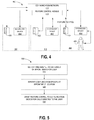
- FIG. 5 is a flowchart illustrating a method of operating a communications system according to one example.
- FIG. 6 is a flowchart illustrating a method of operating a communications system according to one example.
- FIG. 7 is a schematic diagram of a feature control module.
- Systems and methods are provided herein for controlling features on end communication devices according to which communication device is in proximity with the intended user.
- Exemplary systems and methods grant feature control to selected communication devices based on an inferred presence of the user nearby the selected communication device.
- feature control is granted to a communication device based on physical activity that indicates presence of the user near the communication device. Such a configuration may allow the system to provide full feature control for a device the user is likely to be using while still allowing a common address of record with multiple other devices registered to the same user.
- FIG. 1 illustrates a communications system 100 that includes a communications network 110 configured to facilitate a communication session between a user 120 and one or more third parties (not shown).
- the user 120 may have access to a plurality of communication devices 130 , 132 , 134 located at a plurality of locations 140 , 142 , 144 . Though shown at fixed locations, it will be appreciated that the locations 140 , 142 , 144 may be transitory, fixed, or some combination thereof. Further, a number of communication devices may be located at any number of locations.
- the communications system 100 includes a feature control module 115 that is configured to grant feature control to selected communication devices 130 , 132 , 134 based on proximity of the user 120 to the communication devices 130 , 132 , 134 .
- Features that may be controlled as described herein may include the ability to send calls directly to voicemail, call forwarding, voicemail features, and other features related to the control or access of a communication session, such as a call.
- the feature control module 115 is implemented in the communication network 110 . In other examples, the feature control module 115 may be separate from the communication network, implemented in the communication devices 130 , 132 , 134 , or implemented in some other manner. Proximity of the user 120 to the communication devices 130 , 132 , 134 may be inferred in several ways, as will also be discussed in more detail herein.
- the communications network 110 is operatively associated with each of the communication devices 130 , 132 , 134 .
- the communications network 110 may be configured to perform the methods shown in FIG. 2A and FIG. 2B .
- FIG. 2A illustrates a method 200 of initially establishing feature control for communication devices associated with a user based on a location of the user.
- the method 200 begins at step 210 when the communications network 110 receives a request to initiate a communications session with the user 120 .
- the request is directed to the communication devices 130 , 132 , 134 associated with the user 120 at step 215 .
- Steps 210 and 220 may be optional or may be part of an initial process for initially determining to which communication device to grant feature control.
- the communication session may begin at any point during the method. Further, it will be appreciated that the management of feature control may be performed independently of the actual conduct of the communications session if so desired.
- the user 120 may move between any of the locations 140 , 142 , 144 as the user so desires.
- it may be desirable to direct the request to a variety of locations but to grant feature control only to a communication device at the location the user is likely present.
- the method continues at step 220 when the feature control module 115 identifies a location of the user 120 .
- the feature control module 115 identifies the location of the user 120 through inferences. In other examples, direct determination of the user's location may be performed.
- Various processes are described herein for inferring the location of the user 120 as well as for directly determining the user's location. Several exemplary processes will be described in more detail at appropriate points hereinafter.
- the communication devices 130 , 132 , 134 are located at various locations 140 , 142 , 144 .
- the location of the user 120 has been identified, at step 230 at least one of the communication devices in proximity to the inferred location of the user 120 is identified.
- the feature control module 115 grants feature control for communication sessions to selected communication device(s) based on the identification of the inferred location.
- FIG. 2A illustrates a method of initially establishing feature control for communication devices associated with a user based on an inferred location of the user
- FIG. 2B illustrates a method 245 of managing feature control among various communication devices 130 , 132 , 134 .
- Feature control may be granted to the appropriate communication devices 130 , 132 , 134 in a dynamic manner as the user 120 moves between various locations 140 , 142 , 144 .
- determinations as to whether feature control should be granted to a given device may occur independently of requests to initiate communication sessions with the user or even independently of the actual conduct of the communication sessions.
- the communications system 100 may monitor the location of the user at step 250 constantly or periodically. In other examples, monitoring the location of the user 120 according to step 250 may be performed in response to a request to initiate a communication session with the user 120 .
- the method 245 also includes identifying communication devices at or near the user's location at step 260 . Thereafter, if the communication device(s) at or near the user's location have feature control already granted to them (YES, step 270 ), the communications system 100 continues to monitor the location of the user 120 . If, however, the communication devices at the user's location have not been granted feature control (NO, step 270 ), at step 280 the communication devices at the user's location are granted feature control. Thereafter, tracking of the location of the user 120 and the feature control status of communication devices at those locations continue as shown.
- feature control may flow with the location of the user 120 based on inferences about the user's location. Exemplary methods of inferring a user's location will now be described in more detail.
- FIGS. 3A and 3B illustrate a communications system 300 that is configured to infer the location of a user 320 .
- the communications system 300 includes a communications network 310 having a feature control module 315 that is configured to infer the presence of a user at various locations 340 , 342 , 344 , identify which of the communication devices 330 , 332 , 334 are at the inferred location, and grant feature control to a selected device or devices.
- the communications system 300 includes sensors 350 , 352 , 354 positioned at each of the locations 340 , 342 , 344 respectively.
- the sensors 350 , 352 , 354 may be configured to detect the presence of a secondary device 360 that is usually within the control of the user 320 .
- the sensors 350 , 352 , 354 may be configured to detect the presence of devices utilizing short range wireless signals.
- Exemplary short range wireless signals include wireless devices, such as mobile devices, wireless mobile headsets and other such devices.
- the sensors 350 , 352 , 354 may be configured to detect the signals, analyze the signals, and determine whether the secondary device 360 is associated with the user 320 . If the sensors 350 , 352 , 354 detect a signal indicative that the secondary device 360 is a device associated with the user 320 , it may be inferred that the user 320 is at the location corresponding to the sensor.
- the sensor 354 at location 344 detects the presence of the secondary device 360 .
- the feature control module 315 grants feature control to the communication device 334 at location 344 .
- the sensors 350 , 352 , 354 are shown separate from the communication devices 330 , 332 , 334 for ease of reference.
- the sensors 350 , 352 , 354 may be integrated into the communication devices 330 , 332 , 334 .
- a sensor integrated with a deskphone may detect via short range wireless signals the presence of the user's cell phone or other secondary device.
- the desk phone would then know that the user is likely nearby the desk phone, and can therefore limit feature control to the desk phone for the period of time during which the user is nearby the desk phone.
- Feature control would be taken away from the other communication devices 330 , 332 registered to the same user, while preserving the fundamental benefit of parallel forking.
- the feature control module 315 withdraws feature control from the communication device 334 .
- Feature control is transferred to the communication device 332 at the location in which the sensor 352 detects the presence of the secondary device 360 .
- the sensors 350 , 352 , 354 may be physical buttons on the communication devices 330 , 332 , 334 .
- the sensors 350 , 352 , 354 may be actuated by the user 320 to indicate presence. This may be appropriate in a scenario whereby the phone is already located in an area linked to a particular user—such as in an office or study. The user 320 could actuate the button to indicate his/her presence nearby the phone. As in the examples above, feature control could be granted to that phone and taken away from other devices.
- the sensors 350 , 352 , 354 are coupled directly with the communication network 310 and/or the feature control module 315 . In other examples, the sensors 350 , 352 , 354 may be in communication with the communication devices 330 , 332 , 334 alternatively or in addition to coupling directly to the communication network 310 .
- the secondary device 360 may be a passive secondary device. Passive secondary devices may include credentials, such as badges, radio frequency identification (RFID) tags, and the like.
- the sensors 350 , 352 , 354 may be a card or badge reader. Such a sensor may be separate from or integrated into the communications 330 , 332 , 334 as desired.
- the user 320 would swipe a badge or card when entering an area, such as a lab, office, or library. Feature control would then be transferred to the phone in that area (this assumes that the user is already logged into that phone). Feature control may then be taken away from other communication devices registered to the same user, while preserving the fundamental benefit of parallel forking.
- FIGS. 3A and 3B illustrate examples in which the presence of a secondary device is detected in order to infer the presence of a user at a plurality of locations.
- FIG. 4 illustrates a communications system 400 in which a communications network 410 includes a feature control module 415 that grants feature control to various communications devices 430 , 432 , 434 based on interaction of a user 420 with secondary devices 460 , 462 , 464 to infer the presence of the user 420 at various locations 440 , 442 , 444 .
- Exemplary secondary devices include, without limitation peripheral devices such as keyboards, mice, or other devices.
- peripheral devices such as keyboards, mice, or other devices.
- the feature control module 415 grants feature control to the communication device 434 at the location 444 in which the presence of the user 420 has been inferred and withdraws feature control from the other secondary devices 460 , 462 .
- the feature control module 415 may grant feature control to secondary devices when the inferred location of the user 420 changes in a similar manner as described above.
- User interaction with computing devices may also be used to infer the location of a user.
- FIG. 5 is a flowchart illustrating a method 500 of operating a communications system according to one example.
- the method begins by identifying and analyzing occurrences of appointments for a user at step 510 .
- the communications system may have access to a user's appointment calendar. It will be appreciated that appointments often include information about the time and location of the appointment. Accordingly, analyzing appointments for the user may include identifying the time and location of each of the appointments.
- the method continues by identifying communication devices associated with the user at the appointment location. If the user is scheduled to be present at a location in which a communication device is located, then at step 530 the method may include granting feature control to the communication device, if any, present at the location of the appointment during the time of the appointment. For instance, if a user's calendar indicates that she is in a lab area, then feature control can be granted to a phone in the lab area.
- FIG. 6 illustrates a flowchart of a method 600 of operating a communications system in which a location of the user is determined through voice analysis.
- the method 600 begins by receiving a request to initiate a communications session with a user at step 610 and directing the request to communication devices associated with the user at step 620 .
- initiation of the communication is detected.
- the method may include detecting that a phone call has been answered.
- the method then includes performing voice analytics on the communications session. If the voice analytics indicate the actual user is the intended user (YES, step 650 ), the location of the user is verified as being near the communication device at step 660 and feature control is granted to the communication device at step 670 . If, however, the voice analytics indicate the actual user is not the intended user (NO, step 650 ) the communications session is terminated at step 680 .
- FIG. 7 illustrates an exemplary feature control module 700 according to one example.
- Feature control module 700 may be representative of feature control modules 115 , 315 , 415 .
- Feature control module 700 includes processing system 701 , storage system 703 , software 704 , user interface 705 , and communication interface 707 . It should be understood that some elements could be omitted, such as user interface 705 .
- Processing system 701 is linked to storage system 703 , user interface 705 , and communication interface 707 .
- Storage system 703 stores software 704 , executable in operation by processing system 701 .
- Communication interface 707 comprises a network card, network interface, port, or interface circuitry that allows the feature control module 700 to communicate with communication devices and/or sensors over a variety of networks.
- Communication interface 707 may also include a memory device, software, processing circuitry, or some other device.
- Communication interface 707 may use various communication protocols, such as time division multiplex, internet, Ethernet, wireless, or some other communication format—including combinations thereof—to exchange communications as described herein for communication devices.
- User interface 705 comprises components that interact with a user and/or other devices to receive inputs and communications and to present media and/or information.
- User interface 705 may include a speaker, microphone, buttons, lights, display screen, mouse, keyboard, or some other user input/output apparatus—including combinations thereof. In other examples, the user interface 705 may be omitted.
- user interface 705 includes peripheral device 709 , audio device 711 , and visual device 713 .
- Peripheral device 709 could be any device that can receive or output user communications, such as a keyboard, mouse, or other such device.
- audio device 711 is any device capable of receiving or outputting user communications, such as voice communications. Examples of audio device 711 include speakers, headphones, earphones, and microphones.
- Visual device 713 is any device capable of displaying images to a user. An example of a visual device 713 is a display screen.
- Processing system 701 may comprise a microprocessor and other circuitry that retrieves and executes software 704 from storage system 703 .
- Storage system 703 comprises a disk drive, flash drive, data storage circuitry, or some other memory apparatus.
- Processing system 701 is typically mounted on a circuit board that may also hold storage system 703 and portions of communication interface 707 and user interface 705 .
- Software 704 comprises computer programs, firmware, or some other form of machine-readable processing instructions.
- Software 704 may include an operating system, utilities, drivers, network interfaces, applications, virtual machines, or some other type of software.
- software 704 When executed by processing system 701 , software 704 directs processing system 701 to operate the feature control module 700 to perform as described herein for feature control modules 115 , 315 , and 415 .
Abstract
Description
Claims (16)
Priority Applications (1)
| Application Number | Priority Date | Filing Date | Title |
|---|---|---|---|
| US13/037,079 US8625468B2 (en) | 2011-02-28 | 2011-02-28 | Systems and methods for granting feature control based on user location |
Applications Claiming Priority (1)
| Application Number | Priority Date | Filing Date | Title |
|---|---|---|---|
| US13/037,079 US8625468B2 (en) | 2011-02-28 | 2011-02-28 | Systems and methods for granting feature control based on user location |
Publications (2)
| Publication Number | Publication Date |
|---|---|
| US20120218919A1 US20120218919A1 (en) | 2012-08-30 |
| US8625468B2 true US8625468B2 (en) | 2014-01-07 |
Family
ID=46718942
Family Applications (1)
| Application Number | Title | Priority Date | Filing Date |
|---|---|---|---|
| US13/037,079 Active 2031-08-16 US8625468B2 (en) | 2011-02-28 | 2011-02-28 | Systems and methods for granting feature control based on user location |
Country Status (1)
| Country | Link |
|---|---|
| US (1) | US8625468B2 (en) |
Cited By (1)
| Publication number | Priority date | Publication date | Assignee | Title |
|---|---|---|---|---|
| US20070261055A1 (en) * | 2006-05-04 | 2007-11-08 | Samsung Electronics Co., Ltd. | Method and system for the generic and flexible access of available tasks through a user interface |
Families Citing this family (3)
| Publication number | Priority date | Publication date | Assignee | Title |
|---|---|---|---|---|
| US8844050B1 (en) * | 2013-03-15 | 2014-09-23 | Athoc, Inc. | Personnel crisis communications management and personnel status tracking system |
| WO2015060757A1 (en) * | 2013-10-25 | 2015-04-30 | Telefonaktiebolaget L M Ericsson (Publ) | Method and application server for executing a service-related operation for a device user |
| US10117178B2 (en) * | 2015-11-19 | 2018-10-30 | Dell Products L.P. | Simultaneous power control among multiple devices per context |
Citations (14)
| Publication number | Priority date | Publication date | Assignee | Title |
|---|---|---|---|---|
| US5493692A (en) | 1993-12-03 | 1996-02-20 | Xerox Corporation | Selective delivery of electronic messages in a multiple computer system based on context and environment of a user |
| US5544321A (en) | 1993-12-03 | 1996-08-06 | Xerox Corporation | System for granting ownership of device by user based on requested level of ownership, present state of the device, and the context of the device |
| US5812865A (en) | 1993-12-03 | 1998-09-22 | Xerox Corporation | Specifying and establishing communication data paths between particular media devices in multiple media device computing systems based on context of a user or users |
| US6865680B1 (en) | 2000-10-31 | 2005-03-08 | Yodlee.Com, Inc. | Method and apparatus enabling automatic login for wireless internet-capable devices |
| US7099668B2 (en) * | 2000-08-04 | 2006-08-29 | Siemens Aktiengesellschaft | Position-dependent control of features of a communications system |
| US7206582B2 (en) * | 2004-12-27 | 2007-04-17 | Newstep Networks Inc. | Method, system and apparatus for call path reconfiguration |
| US20090316688A1 (en) | 2006-07-13 | 2009-12-24 | Venkat Srinivas Meenavalli | Method for controlling advanced multimedia features and supplemtary services in sip-based phones and a system employing thereof |
| US7653398B2 (en) * | 2005-10-19 | 2010-01-26 | Research In Motion Limited | Geographical network initiated wireless device feature control |
| US20100115627A1 (en) * | 2008-11-05 | 2010-05-06 | At&T Intellectual Property I, L.P. | Apparatus and method for protecting media content rights |
| US7779072B2 (en) * | 1999-11-08 | 2010-08-17 | Verizon Business Global Llc | SIP-based feature control |
| US7831199B2 (en) * | 2006-01-03 | 2010-11-09 | Apple Inc. | Media data exchange, transfer or delivery for portable electronic devices |
| US7830823B2 (en) * | 2005-06-07 | 2010-11-09 | Siemens Enterprise Communications, Inc. | SIP telephone feature control |
| US8104091B2 (en) * | 2008-03-07 | 2012-01-24 | Samsung Electronics Co., Ltd. | System and method for wireless communication network having proximity control based on authorization token |
| US20120169880A1 (en) * | 2010-12-31 | 2012-07-05 | Schneider Electric Buildings Llc | Method and system for video-based gesture recognition to assist in access control |
-
2011
- 2011-02-28 US US13/037,079 patent/US8625468B2/en active Active
Patent Citations (14)
| Publication number | Priority date | Publication date | Assignee | Title |
|---|---|---|---|---|
| US5544321A (en) | 1993-12-03 | 1996-08-06 | Xerox Corporation | System for granting ownership of device by user based on requested level of ownership, present state of the device, and the context of the device |
| US5812865A (en) | 1993-12-03 | 1998-09-22 | Xerox Corporation | Specifying and establishing communication data paths between particular media devices in multiple media device computing systems based on context of a user or users |
| US5493692A (en) | 1993-12-03 | 1996-02-20 | Xerox Corporation | Selective delivery of electronic messages in a multiple computer system based on context and environment of a user |
| US7779072B2 (en) * | 1999-11-08 | 2010-08-17 | Verizon Business Global Llc | SIP-based feature control |
| US7099668B2 (en) * | 2000-08-04 | 2006-08-29 | Siemens Aktiengesellschaft | Position-dependent control of features of a communications system |
| US6865680B1 (en) | 2000-10-31 | 2005-03-08 | Yodlee.Com, Inc. | Method and apparatus enabling automatic login for wireless internet-capable devices |
| US7206582B2 (en) * | 2004-12-27 | 2007-04-17 | Newstep Networks Inc. | Method, system and apparatus for call path reconfiguration |
| US7830823B2 (en) * | 2005-06-07 | 2010-11-09 | Siemens Enterprise Communications, Inc. | SIP telephone feature control |
| US7653398B2 (en) * | 2005-10-19 | 2010-01-26 | Research In Motion Limited | Geographical network initiated wireless device feature control |
| US7831199B2 (en) * | 2006-01-03 | 2010-11-09 | Apple Inc. | Media data exchange, transfer or delivery for portable electronic devices |
| US20090316688A1 (en) | 2006-07-13 | 2009-12-24 | Venkat Srinivas Meenavalli | Method for controlling advanced multimedia features and supplemtary services in sip-based phones and a system employing thereof |
| US8104091B2 (en) * | 2008-03-07 | 2012-01-24 | Samsung Electronics Co., Ltd. | System and method for wireless communication network having proximity control based on authorization token |
| US20100115627A1 (en) * | 2008-11-05 | 2010-05-06 | At&T Intellectual Property I, L.P. | Apparatus and method for protecting media content rights |
| US20120169880A1 (en) * | 2010-12-31 | 2012-07-05 | Schneider Electric Buildings Llc | Method and system for video-based gesture recognition to assist in access control |
Cited By (1)
| Publication number | Priority date | Publication date | Assignee | Title |
|---|---|---|---|---|
| US20070261055A1 (en) * | 2006-05-04 | 2007-11-08 | Samsung Electronics Co., Ltd. | Method and system for the generic and flexible access of available tasks through a user interface |
Also Published As
| Publication number | Publication date |
|---|---|
| US20120218919A1 (en) | 2012-08-30 |
Similar Documents
| Publication | Publication Date | Title |
|---|---|---|
| EP3232299B1 (en) | Physical key component, terminal, and touch response method and device | |
| RU2638938C2 (en) | Method and device for alerting incoming call | |
| US10643619B2 (en) | Dynamic dispatcher electronic digital assistant monitoring in a mobile radio system | |
| CN105933899A (en) | Access method and device of wireless access point | |
| US20220264298A1 (en) | Inference-based detection of proximity changes | |
| CN109658927A (en) | Wake-up processing method, device and the management equipment of smart machine | |
| CN105979501B (en) | Resource allocation methods and device | |
| US11356562B2 (en) | Transferring an active telephone conversation | |
| US20190068734A1 (en) | Notification api for external identification | |
| CN107079310A (en) | Obtain, send the method and device of system information | |
| CN106535291A (en) | SIM card selection method and device | |
| US8625468B2 (en) | Systems and methods for granting feature control based on user location | |
| CN107608561A (en) | Touch-screen control method and device | |
| CN106791087A (en) | The storage method of information, device and equipment | |
| CN106383627A (en) | Information displaying method and apparatus | |
| CN107820684A (en) | Channel Detection, method for sending information, device and communication equipment | |
| CN106462378A (en) | Display method, apparatus and automobile data recorder | |
| CN106604230A (en) | Region configuration method and region configuration device | |
| CN109165651A (en) | A kind of identification code recognition methods, terminal and computer readable storage medium | |
| CN105204713A (en) | Incoming call responding method and device | |
| EP3934217B1 (en) | Reminding task processing method, terminal, and computer readable storage medium | |
| CN108319835A (en) | User's space access control method, device, equipment and storage medium | |
| CN106533798A (en) | Detection method and device | |
| AU2014346878B2 (en) | Digital glass enhanced media system | |
| CN104063423B (en) | A kind of method and device for determining position |
Legal Events
| Date | Code | Title | Description |
|---|---|---|---|
| AS | Assignment |
Owner name: AVAYA INC., NEW JERSEY Free format text: ASSIGNMENT OF ASSIGNORS INTEREST;ASSIGNORS:KESSELRING, ANA;KRAHN, RENEE F.;CHRISS, WILLIAM HOWARD;AND OTHERS;SIGNING DATES FROM 20110215 TO 20110228;REEL/FRAME:025874/0284 |
|
| AS | Assignment |
Owner name: THE BANK OF NEW YORK MELLON TRUST COMPANY, N.A., PENNSYLVANIA Free format text: SECURITY AGREEMENT;ASSIGNOR:AVAYA, INC.;REEL/FRAME:029608/0256 Effective date: 20121221 Owner name: THE BANK OF NEW YORK MELLON TRUST COMPANY, N.A., P Free format text: SECURITY AGREEMENT;ASSIGNOR:AVAYA, INC.;REEL/FRAME:029608/0256 Effective date: 20121221 |
|
| AS | Assignment |
Owner name: BANK OF NEW YORK MELLON TRUST COMPANY, N.A., THE, PENNSYLVANIA Free format text: SECURITY AGREEMENT;ASSIGNOR:AVAYA, INC.;REEL/FRAME:030083/0639 Effective date: 20130307 Owner name: BANK OF NEW YORK MELLON TRUST COMPANY, N.A., THE, Free format text: SECURITY AGREEMENT;ASSIGNOR:AVAYA, INC.;REEL/FRAME:030083/0639 Effective date: 20130307 |
|
| STCF | Information on status: patent grant |
Free format text: PATENTED CASE |
|
| FEPP | Fee payment procedure |
Free format text: PAYOR NUMBER ASSIGNED (ORIGINAL EVENT CODE: ASPN); ENTITY STATUS OF PATENT OWNER: LARGE ENTITY |
|
| AS | Assignment |
Owner name: CITIBANK, N.A., AS ADMINISTRATIVE AGENT, NEW YORK Free format text: SECURITY INTEREST;ASSIGNORS:AVAYA INC.;AVAYA INTEGRATED CABINET SOLUTIONS INC.;OCTEL COMMUNICATIONS CORPORATION;AND OTHERS;REEL/FRAME:041576/0001 Effective date: 20170124 |
|
| FPAY | Fee payment |
Year of fee payment: 4 |
|
| AS | Assignment |
Owner name: SILICON VALLEY BANK, CALIFORNIA Free format text: SECOND AMENDED AND RESTATED PATENT AND TRADEMARK SECURITY AGREEMENT;ASSIGNOR:EXTREME NETWORKS, INC.;REEL/FRAME:043200/0614 Effective date: 20170714 |
|
| AS | Assignment |
Owner name: EXTREME NETWORKS, INC., CALIFORNIA Free format text: ASSIGNMENT OF ASSIGNORS INTEREST;ASSIGNORS:AVAYA INC.;AVAYA COMMUNICATION ISRAEL LTD;AVAYA HOLDINGS LIMITED;REEL/FRAME:043569/0047 Effective date: 20170714 |
|
| AS | Assignment |
Owner name: SILICON VALLEY BANK, CALIFORNIA Free format text: THIRD AMENDED AND RESTATED PATENT AND TRADEMARK SECURITY AGREEMENT;ASSIGNOR:EXTREME NETWORKS, INC.;REEL/FRAME:044639/0300 Effective date: 20171027 |
|
| AS | Assignment |
Owner name: AVAYA INTEGRATED CABINET SOLUTIONS INC., CALIFORNIA Free format text: BANKRUPTCY COURT ORDER RELEASING ALL LIENS INCLUDING THE SECURITY INTEREST RECORDED AT REEL/FRAME 041576/0001;ASSIGNOR:CITIBANK, N.A.;REEL/FRAME:044893/0531 Effective date: 20171128 Owner name: OCTEL COMMUNICATIONS LLC (FORMERLY KNOWN AS OCTEL COMMUNICATIONS CORPORATION), CALIFORNIA Free format text: BANKRUPTCY COURT ORDER RELEASING ALL LIENS INCLUDING THE SECURITY INTEREST RECORDED AT REEL/FRAME 041576/0001;ASSIGNOR:CITIBANK, N.A.;REEL/FRAME:044893/0531 Effective date: 20171128 Owner name: AVAYA INC., CALIFORNIA Free format text: BANKRUPTCY COURT ORDER RELEASING ALL LIENS INCLUDING THE SECURITY INTEREST RECORDED AT REEL/FRAME 029608/0256;ASSIGNOR:THE BANK OF NEW YORK MELLON TRUST COMPANY, N.A.;REEL/FRAME:044891/0801 Effective date: 20171128 Owner name: VPNET TECHNOLOGIES, INC., CALIFORNIA Free format text: BANKRUPTCY COURT ORDER RELEASING ALL LIENS INCLUDING THE SECURITY INTEREST RECORDED AT REEL/FRAME 041576/0001;ASSIGNOR:CITIBANK, N.A.;REEL/FRAME:044893/0531 Effective date: 20171128 Owner name: OCTEL COMMUNICATIONS LLC (FORMERLY KNOWN AS OCTEL Free format text: BANKRUPTCY COURT ORDER RELEASING ALL LIENS INCLUDING THE SECURITY INTEREST RECORDED AT REEL/FRAME 041576/0001;ASSIGNOR:CITIBANK, N.A.;REEL/FRAME:044893/0531 Effective date: 20171128 Owner name: AVAYA INC., CALIFORNIA Free format text: BANKRUPTCY COURT ORDER RELEASING ALL LIENS INCLUDING THE SECURITY INTEREST RECORDED AT REEL/FRAME 041576/0001;ASSIGNOR:CITIBANK, N.A.;REEL/FRAME:044893/0531 Effective date: 20171128 Owner name: AVAYA INTEGRATED CABINET SOLUTIONS INC., CALIFORNI Free format text: BANKRUPTCY COURT ORDER RELEASING ALL LIENS INCLUDING THE SECURITY INTEREST RECORDED AT REEL/FRAME 041576/0001;ASSIGNOR:CITIBANK, N.A.;REEL/FRAME:044893/0531 Effective date: 20171128 Owner name: AVAYA INC., CALIFORNIA Free format text: BANKRUPTCY COURT ORDER RELEASING ALL LIENS INCLUDING THE SECURITY INTEREST RECORDED AT REEL/FRAME 030083/0639;ASSIGNOR:THE BANK OF NEW YORK MELLON TRUST COMPANY, N.A.;REEL/FRAME:045012/0666 Effective date: 20171128 |
|
| AS | Assignment |
Owner name: BANK OF MONTREAL, NEW YORK Free format text: SECURITY INTEREST;ASSIGNOR:EXTREME NETWORKS, INC.;REEL/FRAME:046050/0546 Effective date: 20180501 Owner name: EXTREME NETWORKS, INC., CALIFORNIA Free format text: RELEASE BY SECURED PARTY;ASSIGNOR:SILICON VALLEY BANK;REEL/FRAME:046051/0775 Effective date: 20180501 |
|
| MAFP | Maintenance fee payment |
Free format text: PAYMENT OF MAINTENANCE FEE, 8TH YEAR, LARGE ENTITY (ORIGINAL EVENT CODE: M1552); ENTITY STATUS OF PATENT OWNER: LARGE ENTITY Year of fee payment: 8 |
|
| AS | Assignment |
Owner name: BANK OF MONTREAL, NEW YORK Free format text: AMENDED SECURITY AGREEMENT;ASSIGNORS:EXTREME NETWORKS, INC.;AEROHIVE NETWORKS, INC.;REEL/FRAME:064782/0971 Effective date: 20230818 |