US8645111B2 - Magnetic control plane - Google Patents
Magnetic control plane Download PDFInfo
- Publication number
- US8645111B2 US8645111B2 US11/117,440 US11744005A US8645111B2 US 8645111 B2 US8645111 B2 US 8645111B2 US 11744005 A US11744005 A US 11744005A US 8645111 B2 US8645111 B2 US 8645111B2
- Authority
- US
- United States
- Prior art keywords
- magnetic control
- control plane
- model
- handle
- plane
- Prior art date
- Legal status (The legal status is an assumption and is not a legal conclusion. Google has not performed a legal analysis and makes no representation as to the accuracy of the status listed.)
- Active - Reinstated, expires
Links
Images


Classifications
-
- G—PHYSICS
- G06—COMPUTING; CALCULATING OR COUNTING
- G06F—ELECTRIC DIGITAL DATA PROCESSING
- G06F30/00—Computer-aided design [CAD]
Definitions
- the invention relates to computer-aided modeling and in particular to enabling modification of a model, such as to simultaneous transfer of a plurality of parts or one end of the parts locating on the same plane.
- Modeling means that an object is represented by a model.
- the development of data processing systems and computers has transformed the modeling into a computerized process, in which a model is created by defining parts each having handles and given characteristics, such as a first end, a second end, location and a shape.
- the objective of the modeling is to make the model work in the same way as its real-world object and that the model provides information, by means of which the object can be implemented in the real world.
- the model “lives” in the course of modeling and every now and then a situation arises, where one end of several different parts need to be transferred a given distance.
- the object of the invention is thus to provide a method and equipment implementing the method to the effect that the above problem can be solved such that the objects to be modified need not be selected separately.
- the object of the invention is achieved with a method, a system and a computer software product, which are characterized by what is disclosed in the independent claims.
- the preferred embodiments of the invention are disclosed in the dependent claims.
- the invention is based on a magnetic control plane, to which handles of model parts locating thereon adhere without specific definitions provided by the user and the handles, for instance, move along with the plane if the plane is transferred.
- the only thing the modeler, i.e. the user, needs to do is to create a plane and define the plane magnetic at some stage of modeling. On the basis of this data provided by the user the modeling system knows all that needs to be transferred when transferring the magnetic control plane.
- the invention has an advantage that it enables implementation of extremely complicated transfers and stretches in an easy and user-friendly manner. For instance, if a wall line is shifted, it will suffice in the solution of the invention that the wall line will be defined as a magnetic surface, whereafter the handles on the wall line, such as the handles of the beams and the slabs, will be shifted accordingly, whereas in the prior art solution it would be necessary to shift the ends of the slabs and each individual beam either separately or attached to the wall line, otherwise a beam, for instance, would either exceed the wall line or fall short of it.
- FIG. 1 is a simplified block diagram of the architecture of an exemplary system
- FIGS. 2A , 2 B, 2 C and 2 D illustrate a magnetic control plane and its basic types
- FIGS. 3 and 4 illustrate an embodiment of the invention
- FIGS. 5 , 6 and 7 illustrate another embodiment of the invention.
- FIG. 8 illustrates transfer of a single handle in accordance with the invention.
- the present invention can be applied in connection with any template-based modeling or -drawing system, including so-called CAD-type systems and systems based on parametric modeling.
- CAD-type systems a modeled part consists of edges, and the shape and size of the part are the essence of the modeled part.
- a beam for instance, is modeled by drawing each side of the beam, whereafter they are assembled into a beam with a shape and size being an integral part thereof.
- the invention is particularly well suited for modeling systems, in which the physical characteristics of a piece are indicated by attributes, i.e. by using parameters.
- the modeled object is not bound to the physical characteristics of the part, but the geometry of the object can be created by means of various parameters when necessary.
- a beam can be modeled, for instance, by giving it a start point and an end point and various definitions that determine the physical characteristics of the beam. In parametric systems it is thus possible to model the beam such that the shape and size of the beam are no longer physically associated with the beam.
- the run-time database comprises data to be stored in a disk memory, and data already store therein, on an overall object modeled, or to be modeled, for instance, on a building.
- the run-time database may also be located in the main memory.
- Some other embodiments of the invention only utilize data in the random access memory, which are never stored and which will be erased, when the work to be processed is closed.
- Various programming techniques, data storing in the memory and implementations of databases, as well as the use of the Internet for data transmission and as a common application platform, are under constant development. This development may require extra changes in the invention. Therefore, all terms and expressions should be interpreted broadly, and they are intended to illustrate, not to restrict, the invention.
- FIG. 1 shows a simplified modeling system and it only depicts the most substantial parts of the logic units in the system, the implementation of which may deviate from what is shown. It is apparent to a person skilled in the art that the system may also comprise other functions and structures that need not be described in greater detail herein. A more detailed structure of the system is irrelevant to the actual invention.
- the modeling system 1 illustrated in FIG. 1 comprises a personal computer having a user interface 1 - 1 , a processor 1 - 2 and memory 1 - 3 .
- the user interface 1 - 1 is the interface of a user, i.e. a person processing the model, to the modeling system. Through the interface the user can create a model, modify the model, view it, print out desired images, reports, etc. How data are entered in the modeling system is not relevant to the invention. The manners to provide data described below are only given as examples and they do not restrict the invention in any way.
- the processor 1 - 2 executes operations of the invention.
- the data optionally stored in the memory 1 - 3 according to the invention vary from one embodiment to another and they will be described later on in the text.
- the data to be stored are stored in a memory, for instance, in a file, and the data stored and to be stored during processing will be a so-called database in the main memory, into which the stored data are read from the disk memory and where their processing is faster.
- the database data or at least the changed data, are stored in the disk memory.
- the memory 1 - 3 comprises a so-called random access memory, where process-time data may be maintained, i.e. the data that will not be stored when the processing is over.
- the modeling system set forth in FIG. 1 represents the simplest modeling system.
- the user interface can be a terminal device and the memory, or part of the memory, can be a database, with which the terminal device communicates through a server.
- the server executes functions of the processor in the exemplary system, or at least some of them, whereby the terminal device may also execute the processor functions of the exemplary system.
- FIG. 2A shows the definition of a magnetic plane two-dimensionally and FIGS. 2B , 2 C and 2 D illustrate two different basic types of the magnetic plane of the invention with their effects. Due to the two-dimensional presentation the magnetic control plane 2 is shown as a broken line in FIGS. 2A , 2 B, 2 C and 2 D.
- FIG. 2A there is modeled an object that comprises at least parts A, B, C and D.
- the object is modeled to have a magnetic control plane 2 , on which there are handle A 1 of part A, handle B 1 of part B and handle D 1 of part D.
- Other handles D 2 , D 3 and D 4 of part D are not located on the magnetic control plane, and, for the sake of clarity, other handles of parts A, B and C are not shown in FIG. 2A .
- a handle refers to a point that allows the part to be grabbed and when it is shifted, the shape and/or location of the part will change.
- the handle can be determined separately, for instance, while modeling, one can enter information “midpoint of the left corner side comprises a handle”.
- the determination point of a part i.e. the point, by means of which the modeling system creates the part
- a handle i.e. the point
- the determination point of a part is also a handle.
- parametric modeling handles may include start and end points of the part, a logical plane with which the part is associated, a point calculated on the basis of the parameters of the part, e.g. an intersection of the top surface and end surface of the beam, etc.
- the invention does not restrict in any way the handle or its location, or set any requirements thereto. Also, the order in which the different parts and the magnetic control plane are created is irrelevant to the invention.
- the model was created, for instance by first creating part C, then the magnetic control plane 2 and thereafter parts A, B and D, or by first creating parts A, B, C and D and then the magnetic control plane 2 , or by first creating parts A and D, then the magnetic control plane 2 and thereafter parts B and C, or the creation of the model may have started by creating the magnetic control plane.
- the fact that the magnetic control plane can be determined any time provides an advantage that the invention can be applied to existing old models. In addition, it makes the user's work easier, because he or she need not know in advance possible locations of the magnetic control plane or wait that the model is completed before the magnetic control plane is defined.
- the magnetism of the plane can also be switched off at any stage of modeling.
- the switched-off magnetism can be switched on again later.
- the plane behaves like any other ordinary plane.
- the definitions of the magnetic control plane advantageously remain in the memory, even though the magnetism of the plane is switched off.
- the definitions of the magnetic control plane can be deleted on switching off the magnetism of the plane.
- the fact that the magnetism can be switched off, when necessary, provides an advantage that the same plane can also be used for other purposes than just for the magnetic control plane. To switch off the magnetism makes it possible that the plane is moved to another location without that the handles on the plane move along.
- the magnetic control plane is generally an auxiliary plane, which is not part of the actual model, but the magnetic control plane of the invention may also be an actual model plane, for instance a slab or a top surface of a slab.
- the magnetic control plane is a finite surface, but it may also be an infinite surface.
- the magnetic control plane may be a plane that is defined like any other plane by three points that are not located on the same straight line.
- the user may also define thickness for the magnetic control plane.
- the magnetic control plane advantageously has thickness to correspond at least to the calculation accuracy of the computer. This is to ensure that the handles appearing on the magnetic control plane will be taken along, even though a slight measuring error would have been made in connection with modeling.
- the magnetic control plane may be in any arbitrary position in the three-dimensional space and it can be moved arbitrarily, for instance, by rotation, reflection, shifting horizontally or vertically, etc. It does not have to be a planar surface, but it may be a three-dimensional surface, for instance, a wavy surface or an undulating surface or a surface of a function. The surface may also be planar on one side and three-dimensional, e.g. wavy, on the other side.
- FIGS. 2B and 2C There are two basic types of magnetic control planes: one with selective magnetism and the other with non-selective magnetism. The difference between these two basic types does not appear until the magnetic control plane is moved. This difference is illustrated in FIGS. 2B and 2C .
- the magnetic control plane of FIG. 2B is non-selective, i.e. all handles appearing on the magnetic control plane adhere to the plane. So, the shift of the magnetic control plane from the location of FIG. 2A to the location of FIG. 2B provides a corresponding shift for all handles on the magnetic control plane.
- FIGS. 2A and 2B handles A 1 , B 1 and D 1 move and the modeled parts A, B and D will change accordingly. If part D had been defined only having handle D 1 , the appearance of part D would have remained the same, but the part would have shifted for the same amount as the shift of the magnetic control plane 2 . However, in the example of FIGS. 2A and 2B handles D 2 , D 3 and D 4 of part D did not adhere to the magnetic control plane.
- the magnetic control plane of FIG. 2C is defined selective, i.e. the handles appearing on the magnetic control plane do not necessarily adhere to the plane.
- Definition of selectivity may consist in defining what adheres to the magnetic control plane.
- definition of selectivity may consist in defining what does not adhere to the magnetic control plane.
- the definition of the magnetic control plane is such that the handle (or handles) of part A adheres to the magnetic control plane 2 , but those of parts B and D do not. So, the shift of the magnetic control plane from the position shown in FIG. 2A to the position shown in FIG. 2C provides a corresponding shift of all handles appearing on the magnetic control plane and adhering to the magnetic control plane.
- FIG. 2C the definition of the magnetic control plane is such that the handle (or handles) of part A adheres to the magnetic control plane 2 , but those of parts B and D do not. So, the shift of the magnetic control plane from the position shown in FIG. 2A to the position shown in FIG. 2C provides a corresponding shift of all handles appearing on the magnetic control
- Selectivity can be defined when the plane is defined, or later on, for instance, if it is noted in the course of the shift that all parts should not follow. Selectivity can also be changed during modeling. Selectivity can be defined, for instance, on the basis of the material used (steel adheres, concrete does not), on the basis of the type of the part (beam adheres, slab does not), on the basis of location (those on the third floor level do not adhere, those on the first, second, fourth floor levels and up adhere) or as a combination thereof. It is also possible that a feature is associated with the handle, on the basis of which the selectivity can be defined. The invention does not restrict in any way, how the selectivity is defined, the above examples only illustrate the invention.
- the modeled part will advantageously move as a whole.
- the magnetism can also be utilized when the intention is only to move the modeled object.
- FIG. 2D the magnetic control plane may be non-selective or it may be defined selective such that the handles of parts A, B and D adhere thereto.
- the magnetic control plane 2 ′ is also defined to have thickness such that all handles of part D touch the magnetic control plane 2 ′. So, the whole part D moves (situation in FIG. 2A intended as a starting situation), but parts A and B are stretched. How the whole part D moves depends on the handle definitions. It is assumed in FIG.
- the handles are defined to allow a side transfer such that the original definition direction of the side (e.g. vertical, horizontal etc.) remains the same. If the handles were defined to allow a side transfer, for instance, part D would become oblique. Whereas, if the same or simultaneous transfer of all handles of one part is defined as the whole part transfer, the piece would advantageously become a rhombus that is attached to part D at one point after the transfer in FIG. 2D . There are numerous different definition alternatives and the invention will not restrict them and the use thereof in any way.
- the magnetic control plane can also be utilized during modeling as a so-called snap surface, i.e. an auxiliary surface, in creating new objects or in moving the existing ones.
- a snap surface i.e. an auxiliary surface
- the snap functionality can also be selective.
- FIGS. 3 and 4 illustrate an embodiment of the invention in which the magnetic control plane is always of selective type, but it allows, however, definition of selectivity such that all handles on the magnetic control plane may adhere thereto.
- the implementation of the magnetic control plane is based on geometric relations between the magnetic control plane and the handles, i.e. on relations that are not stored in the database. These relations are also called implicit relations.
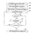
- FIG. 3 illustrates how the magnetic control plane is created in the embodiment in question.
- the user creates a surface by defining the location and size of the surface. The size may be infinite or finite and the surface may have any shape, for instance, rectangular or “amebic”.
- the user defines the created surface as a magnetic control plane and in step 303 defines which items will adhere to the magnetic control plane.
- the magnetic control plane definitions are stored in the database in step 304 .
- the definitions of the magnetic control plane are not used until the plane is transferred. This is illustrated in FIG. 4 .
- the handles locating on the selected magnetic control plane prior to the transfer are collected in a random access memory in step 403 . Collecting is based on the geometric data on the model parts and the definitions of the magnetic control plane in the database. In this embodiment the location of the magnetic control plane prior to transfer is maintained in the random access memory for the time it takes to collect the handles. Thereafter the handles in the random access memory are examined one by one. First, in step 404 , a handle is picked up for processing, thereafter, in step 405 it is checked whether the handle will adhere to the magnetic control plane.
- step 406 If that handle is adhesive, it is transferred in step 406 to correspond the transfer of the magnetic control plane. Then, in step 407 it is checked whether there are handles that have not yet been examined. If there are, step 404 is returned to and the next handle is picked up for processing and the process will proceed from step 404 onwards.
- step 407 When all handles have been examined (step 407 ), the handle locations that were changed are advantageously stored in the database in step 408 and an updated model is displayed to the user.
- step 407 is proceeded to directly in order to check whether there still are unexamined handles.
- magnetic control plane selection by the user generates collection of handles locating on the magnetic control plane into a random access memory, i.e. step 403 is executed prior to step 402 or simultaneously therewith. If the magnetic control plane were not transferred after point 401 , but the user would have selected another part of the model, for instance, in this embodiment the handles collected in step 403 are released, and subsequently when the user selects a magnetic control plane, all steps of the figure are repeated in this embodiment.
- FIGS. 3 and 4 has an advantage that handles on the magnetic control plane are not collected in vain, but they are collected when they are likely to be needed.
- a further advantage is that during modeling there will be no need to monitor whether handles will appear on the plane defined as the magnetic control plane in connection with modeling after defining the plane as the magnetic control plane, because all handles locating on the magnetic control plane at the moment of transfer will be collected and checked in connection with the transfer. It is also an advantage that if the magnetism of the plane is cancelled and the plane was not moved while it was magnetic, data is not collected unnecessarily.
- the relation is explicit, i.e. the handles on the magnetic control plane are collected in a random access memory when the definition of the magnetic control plane is stored in a database, i.e. after step 304 in FIG. 3 .
- it is monitored in connection with modeling whether parts with a handle or handles on the magnetic control plane are being modeled, and when such a handle is detected, it is added to the handles of said magnetic control plane in the random access memory.
- handles are not collected in this embodiment, but after the transfer of the magnetic control plane the handles in the random access memory are examined in the above-described manner (steps 404 to 408 ). In other words, step 402 is omitted in FIG. 4 . It is also possible that only handles that adhere to the plane are stored in the random access memory. In this embodiment all handles in the random access memory are transferred, because their adhesion need not be checked again. If the magnetism of the plane is cancelled, the handles associated with the plane are advantageously deleted from the random access memory by releasing their memory locations.
- handles modeled at a given time interval do not adhere to the magnetic control plane.
- the same can also be implemented by means of time stamps, for instance; the parts that adhere and the ones that do not are filtered on the basis of the time stamps. Instead of the time stamps, the filter may also use some other feature of the part.
- FIGS. 5 , 6 and 7 illustrate another embodiment of the invention in which the magnetic control plane is always of non-selective type and the implementation of the magnetic control plane is based on explicit relations between the magnetic control plane and the definition points, i.e. relations that are created and stored in a database.
- FIG. 5 illustrates how a plane is created in the embodiment.
- the user creates a plane by defining the location and size of the surface.
- the size may be infinite or finite and the plane may have any shape, for instance, rectangular or “amebic”.
- the user defines the created plane as a magnetic control plane.
- the magnetic control plane definitions are stored in the database in step 503 .
- handles appearing on the just created magnetic control plane are collected in step 504
- explicit relations between the handles and the magnetic control plane are created in step 505 and the relations are stored in a database in step 506 . Collecting is based on geometric data on the model parts and on definitions of the magnetic control plane in the database.
- FIG. 6 illustrates the operation of the exemplary system after the magnetic control plane has been created and the user continues modeling elsewhere.
- it is monitored in connection with modeling, in step 601 , whether parts with their handles on the magnetic control plane are being modeled (step 602 ).
- step 602 a relation between the handle and the magnetic control plane is created in step 603 and it is stored in step 604 among the relations of said magnetic control plane in the database and the monitoring of modeling is continued from step 601 .
- the relations are employed when the user transfers the magnetic control plane.
- FIG. 7 the relations of the magnetic control plane in the database are examined one by one.
- a relation is picked up for processing (step 702 )
- the handle indicated by the relation is transferred in step 703 to correspond to the transfer of the magnetic control plane.
- step 704 it is checked in step 704 , whether there still are unexamined relations. If there are, step 702 is returned to in order to pick up the next relation for processing and the process continues from step 702 onwards.
- step 705 the new locations of the handles are stored in the database and an updated model is displayed to the user.
- the relations are advantageously deleted from the memory by releasing their memory locations. It is also possible to retain the relations in the memory and if the plane is rendered magnetic again to start monitoring, and depending on the embodiment, either to update in the relations the handles on the plane that were modeled during the time the magnetism was off, or to leave them non-updated.
- the latter option provides a kind of selective magnetism: handles of the objects modeled at a given time interval do not adhere to the magnetic control plane.
- FIG. 8 illustrates transfer of a magnetic control plane X from a viewpoint of one individual handle in an embodiment of the invention.
- FIG. 8 starts from the fact that the magnetic control plane X, on which the handle is located and to which the handle adheres, is moved in step 801 .
- the magnetic control plane X on which the handle is located and to which the handle adheres, is moved in step 801 .
- step 802 When it is detected that the magnetic control plane X with a handle adhering thereto is being transferred (step 801 ), it is checked in step 802 whether the handle simultaneously appears on another magnetic control plane. If not, the handle will be transferred in accordance with the magnetic control plane X in step 803 . If the handle simultaneously appears on another, optionally on several magnetic control planes (step 802 ), it is checked in step 804 whether the handle moves off one of the magnetic control planes to which it adheres if it is transferred in a corresponding manner with the magnetic control plane X. In other words, in step 804 it is checked whether the handle is able to stay on all the magnetic control planes, to which it adheres.
- the handle does not move off the other magnetic control planes to which the handle adheres, the handle is able to stay on all magnetic control planes even after the transfer and the handle shifts in accordance with the magnetic control plane in step 803 .
- step 804 If it is detected (step 804 ) that the handle transfer corresponding to that of the magnetic control plane X makes the handle move off at least one other magnetic control plane on which it should appear (i.e. to which it adheres) a contradiction arises.
- the modeling program is arranged to ask the user for an instruction in step 805 in a contradicting situation of this kind to the effect that the user can give either a direct instruction or an indirect instruction.
- the direct instruction means here that the user indicates either that the handle moves along with the magnetic control plane X or that the handle does not move along with the magnetic control plane X.
- the indirect instruction means that the user indicates that the fact whether the handle moves along with the magnetic control plane X or not is determined together with the definitions of the modeling program.
- step 807 is performed in accordance with the obtained direct instruction.
- step 808 is performed in accordance with the definitions of the modeling program.
- They may include a hierarchy for various magnetic planes, for instance.
- the hierarchy may be based, for instance, on the type of the magnetic control plane, on how selective the magnetic plane is, on how large proportion of the relations are explicit relations and/or on the creation order of the magnetic control planes and/or on the characteristics of the handle.
- the handle may move, for instance, if it stays on the magnetic control plane to which it adhered first explicitly or implicitly.
- the magnetic control planes may also have an internal hierarchy of their own, whereby the handle may move if it stays on the magnetic control planes that are higher up in the hierarchy than the magnetic control plane X. It should be emphasized that the invention does not restrict the definition rules needed in a contradicting situation in any way.
- the user may have to give a direct instruction and the modeling program need not be provided with internal definitions for contradicting situations.
- the user is not asked anything, but in a contradicting situation the operation follows the internal definitions alone.
- explicit relations it is also possible to prevent the contradicting situations in such a way, for instance, that prior to forming a relation it is checked whether any one relation is already associated with the handle, and the relation is only formed if no relation is associated with the handle.
- the modeling program detects the contradicting situations and asks the user how to act in a contradicting situation.
- the modeling program of the invention can also be implemented such that it will not detect contradicting situations but moves the handle irrespective of its adherence to another magnetic control plane as well.
- the steps in FIGS. 3 , 4 , 5 , 6 and 7 are not in the absolute chronological order, and they can be performed in an order that differs from what is given, or simultaneously. For instance, adherence can be checked in the collecting step or on storing the relations such that only the adhesive handles will be collected or their relations stored. Other operations can be carried out between the described steps, for instance, between creating a plane and defining it a magnetic control plane (steps 301 and 302 as well as 501 and 502 ), or before transferring the handle (step 406 and 703 ) it can be checked, in accordance with FIG. 8 , how the handle is transferred. Other operations can be performed simultaneously with the described operations. Some of the steps described in the figures may also be omitted. Some of the described steps may be replaced by a step that gives a corresponding result. In addition, the definitions of the magnetic control plane, such as thickness or what will adhere to the plane, can be changed any time during the modeling.
- the definitions of the magnetic control plane may also be located in the random access memory alone, whereby they will disappear when the processing of the model is over.
- the control plane may also be a completely temporary plane, whereby the control plane definitions remain in the random access memory only for the duration of the use of the control plane (definition and subsequent transfer). If the magnetic control plane is needed when the model will be subsequently processed, it will have to be redefined.
- This kind of an embodiment has an advantage that the definitions are not stored unnecessarily in the model, nor will they unnecessarily increase the memory and processing capacity required by the model.
- the modeling system implementing the functionality of the present invention comprises, in addition to means necessary for prior art surface modeling, means for providing and utilizing magnetic control planes.
- the modeling system may also comprise means for storing the magnetic control planes and/or means for storing the relations created thereby.
- the modeling system of the invention comprises means for implementing at least one embodiment of the invention.
- Conventional personal computers or terminal equipment and database servers comprise processors and memory that can be utilized in the functions of the invention. All changes and configurations needed for the implementation of the invention can be executed as added or updated software routines, with application specific integrated circuits (ASIC) and/or by otherwise configuring the existing system, particularly the modeling program.
- the software/software routines can be stored in any data storage means readable with a computer.
Abstract
Description
Claims (22)
Priority Applications (1)
| Application Number | Priority Date | Filing Date | Title |
|---|---|---|---|
| US11/117,440 US8645111B2 (en) | 2004-04-30 | 2005-04-29 | Magnetic control plane |
Applications Claiming Priority (4)
| Application Number | Priority Date | Filing Date | Title |
|---|---|---|---|
| FI20040626A FI117219B (en) | 2004-04-30 | 2004-04-30 | Model modification/transfer enabling method in modeling system, involves defining created plane as magnetic control plane so as to transfer magnetic control plane for moving handle associated with model correspondingly |
| FI20040626 | 2004-04-30 | ||
| US57603604P | 2004-06-02 | 2004-06-02 | |
| US11/117,440 US8645111B2 (en) | 2004-04-30 | 2005-04-29 | Magnetic control plane |
Publications (2)
| Publication Number | Publication Date |
|---|---|
| US20050285881A1 US20050285881A1 (en) | 2005-12-29 |
| US8645111B2 true US8645111B2 (en) | 2014-02-04 |
Family
ID=35505190
Family Applications (1)
| Application Number | Title | Priority Date | Filing Date |
|---|---|---|---|
| US11/117,440 Active - Reinstated 2029-05-15 US8645111B2 (en) | 2004-04-30 | 2005-04-29 | Magnetic control plane |
Country Status (1)
| Country | Link |
|---|---|
| US (1) | US8645111B2 (en) |
Citations (7)
| Publication number | Priority date | Publication date | Assignee | Title |
|---|---|---|---|---|
| US4017604A (en) * | 1975-03-03 | 1977-04-12 | Texas Instruments Incorporated | Magnetic bubble chip packaging assembly |
| US5513310A (en) * | 1993-02-08 | 1996-04-30 | Megard; Patrick | Method for selecting a constructed element of a drawing to generate similar elements |
| US5519462A (en) * | 1994-07-21 | 1996-05-21 | Eastman Kodak Company | Dual function magnetic data read circuit for photographic equipment |
| US5856828A (en) * | 1991-12-19 | 1999-01-05 | Aerohydro, Inc. | System of relational entities for object-oriented computer-aided geometric design |
| WO2002003259A1 (en) | 2000-07-04 | 2002-01-10 | David Brian Ninnes | Method and system for generating patterned images |
| JP2002215683A (en) | 2001-01-22 | 2002-08-02 | Amu:Kk | Cad software |
| US6632548B2 (en) * | 2000-07-03 | 2003-10-14 | Fuji Photo Film Co., Ltd. | Magnetic disk comprising a magnetic layer having specific projections distributions |
-
2005
- 2005-04-29 US US11/117,440 patent/US8645111B2/en active Active - Reinstated
Patent Citations (7)
| Publication number | Priority date | Publication date | Assignee | Title |
|---|---|---|---|---|
| US4017604A (en) * | 1975-03-03 | 1977-04-12 | Texas Instruments Incorporated | Magnetic bubble chip packaging assembly |
| US5856828A (en) * | 1991-12-19 | 1999-01-05 | Aerohydro, Inc. | System of relational entities for object-oriented computer-aided geometric design |
| US5513310A (en) * | 1993-02-08 | 1996-04-30 | Megard; Patrick | Method for selecting a constructed element of a drawing to generate similar elements |
| US5519462A (en) * | 1994-07-21 | 1996-05-21 | Eastman Kodak Company | Dual function magnetic data read circuit for photographic equipment |
| US6632548B2 (en) * | 2000-07-03 | 2003-10-14 | Fuji Photo Film Co., Ltd. | Magnetic disk comprising a magnetic layer having specific projections distributions |
| WO2002003259A1 (en) | 2000-07-04 | 2002-01-10 | David Brian Ninnes | Method and system for generating patterned images |
| JP2002215683A (en) | 2001-01-22 | 2002-08-02 | Amu:Kk | Cad software |
Also Published As
| Publication number | Publication date |
|---|---|
| US20050285881A1 (en) | 2005-12-29 |
Similar Documents
| Publication | Publication Date | Title |
|---|---|---|
| US5850535A (en) | Roll-back during regeneration on a computer-aided design system | |
| US6308144B1 (en) | Method and apparatus for providing three-dimensional model associativity | |
| CN105190611B (en) | The method and device extending transversely for database | |
| US5847956A (en) | Automatic trimming of geometric objects in CAD/CAM systems | |
| CA2717802C (en) | Method and apparatus for copying objects in an object-oriented environment using a multiple-transaction technique | |
| KR101925640B1 (en) | Designing a three-dimensional modeled assembly of objects in a three-dimensional scene | |
| JP3657771B2 (en) | 3D model creation device | |
| CN102779202B (en) | Method and apparatus for the executor of selecting object | |
| CN102067132A (en) | System and method for modifying features in a solid model | |
| JP2003509740A (en) | Data exchange between computer aided design systems. | |
| JP2007233565A (en) | Design support program | |
| WO2015055087A1 (en) | Method and device for selecting solid in drawing | |
| JPWO2018185972A1 (en) | Map data generation apparatus and method | |
| US7765240B2 (en) | Computer-aided modeling | |
| EP1091325B1 (en) | Defining parameters for an FEA calculation in a CAD program | |
| US8645111B2 (en) | Magnetic control plane | |
| JPH0816824A (en) | Three-dimensional computer aided design device/method | |
| CN115409310A (en) | System and method for generating and displaying targeted information related to a robot working in an operating environment | |
| JP2010086476A (en) | Design support device and design support program | |
| JP5084702B2 (en) | Analysis data input device, CAE device, analysis data input method, and program | |
| US20130232109A1 (en) | Methods and systems for performing three-way merge of models | |
| CN115391564B (en) | Method for constructing relationship map based on webworker | |
| JP2878697B2 (en) | Shape display processing device | |
| JP3127265B2 (en) | CAE system | |
| JP4549805B2 (en) | Design data generation system, design data generation method, design data generation program |
Legal Events
| Date | Code | Title | Description |
|---|---|---|---|
| AS | Assignment |
Owner name: TEKLA CORPORATION, FINLAND Free format text: ASSIGNMENT OF ASSIGNORS INTEREST;ASSIGNORS:HEIKKONEN, TEEMU;OJALA, IIRO;ROUSU, VILLE;AND OTHERS;SIGNING DATES FROM 20040615 TO 20040622;REEL/FRAME:031307/0470 |
|
| FEPP | Fee payment procedure |
Free format text: MAINTENANCE FEE REMINDER MAILED (ORIGINAL EVENT CODE: REM.) |
|
| LAPS | Lapse for failure to pay maintenance fees |
Free format text: PATENT EXPIRED FOR FAILURE TO PAY MAINTENANCE FEES (ORIGINAL EVENT CODE: EXP.) |
|
| STCH | Information on status: patent discontinuation |
Free format text: PATENT EXPIRED DUE TO NONPAYMENT OF MAINTENANCE FEES UNDER 37 CFR 1.362 |
|
| FP | Lapsed due to failure to pay maintenance fee |
Effective date: 20180204 |
|
| FEPP | Fee payment procedure |
Free format text: SURCHARGE, PETITION TO ACCEPT PYMT AFTER EXP, UNINTENTIONAL (ORIGINAL EVENT CODE: M1558); ENTITY STATUS OF PATENT OWNER: LARGE ENTITY Free format text: PETITION RELATED TO MAINTENANCE FEES FILED (ORIGINAL EVENT CODE: PMFP); ENTITY STATUS OF PATENT OWNER: LARGE ENTITY |
|
| MAFP | Maintenance fee payment |
Free format text: PAYMENT OF MAINTENANCE FEE, 4TH YEAR, LARGE ENTITY (ORIGINAL EVENT CODE: M1551); ENTITY STATUS OF PATENT OWNER: LARGE ENTITY Year of fee payment: 4 |
|
| FEPP | Fee payment procedure |
Free format text: PETITION RELATED TO MAINTENANCE FEES DISMISSED (ORIGINAL EVENT CODE: PMFS); ENTITY STATUS OF PATENT OWNER: LARGE ENTITY |
|
| FEPP | Fee payment procedure |
Free format text: PETITION RELATED TO MAINTENANCE FEES FILED (ORIGINAL EVENT CODE: PMFP); ENTITY STATUS OF PATENT OWNER: LARGE ENTITY |
|
| FEPP | Fee payment procedure |
Free format text: PETITION RELATED TO MAINTENANCE FEES DISMISSED (ORIGINAL EVENT CODE: PMFS); ENTITY STATUS OF PATENT OWNER: LARGE ENTITY |
|
| FEPP | Fee payment procedure |
Free format text: PETITION RELATED TO MAINTENANCE FEES FILED (ORIGINAL EVENT CODE: PMFP); ENTITY STATUS OF PATENT OWNER: LARGE ENTITY |
|
| PRDP | Patent reinstated due to the acceptance of a late maintenance fee |
Effective date: 20210902 |
|
| FEPP | Fee payment procedure |
Free format text: PETITION RELATED TO MAINTENANCE FEES GRANTED (ORIGINAL EVENT CODE: PMFG); ENTITY STATUS OF PATENT OWNER: LARGE ENTITY |
|
| STCF | Information on status: patent grant |
Free format text: PATENTED CASE |
|
| FEPP | Fee payment procedure |
Free format text: 7.5 YR SURCHARGE - LATE PMT W/IN 6 MO, LARGE ENTITY (ORIGINAL EVENT CODE: M1555); ENTITY STATUS OF PATENT OWNER: LARGE ENTITY |
|
| MAFP | Maintenance fee payment |
Free format text: PAYMENT OF MAINTENANCE FEE, 8TH YEAR, LARGE ENTITY (ORIGINAL EVENT CODE: M1552); ENTITY STATUS OF PATENT OWNER: LARGE ENTITY Year of fee payment: 8 |