US8647020B2 - Plastic cable bolt button - Google Patents

Plastic cable bolt button Download PDF

Info

Publication number
US8647020B2
US8647020B2 US13/008,095 US201113008095A US8647020B2 US 8647020 B2 US8647020 B2 US 8647020B2 US 201113008095 A US201113008095 A US 201113008095A US 8647020 B2 US8647020 B2 US 8647020B2
Authority
US
United States
Prior art keywords
cable bolt
sidewall
end portion
bolt button
button
Prior art date
Legal status (The legal status is an assumption and is not a legal conclusion. Google has not performed a legal analysis and makes no representation as to the accuracy of the status listed.)
Expired - Fee Related, expires
Application number
US13/008,095
Other versions
US20110200400A1 (en
Inventor
John C. Stankus
Dakota Faulkner
John Feyrer
John G. Oldsen
Jeffrey J. Stankus
Current Assignee (The listed assignees may be inaccurate. Google has not performed a legal analysis and makes no representation or warranty as to the accuracy of the list.)
FCI Holdings Delaware Inc
Original Assignee
FCI Holdings Delaware Inc
Priority date (The priority date is an assumption and is not a legal conclusion. Google has not performed a legal analysis and makes no representation as to the accuracy of the date listed.)
Filing date
Publication date
Application filed by FCI Holdings Delaware Inc filed Critical FCI Holdings Delaware Inc
Priority to US13/008,095 priority Critical patent/US8647020B2/en
Assigned to FCI HOLDINGS DELAWARE, INC. reassignment FCI HOLDINGS DELAWARE, INC. ASSIGNMENT OF ASSIGNORS INTEREST (SEE DOCUMENT FOR DETAILS). Assignors: OLDSEN, JOHN G., STANKUS, JOHN C., STANKUS, JEFFREY J., FAULKNER, DAKOTA, FEYRER, JOHN
Publication of US20110200400A1 publication Critical patent/US20110200400A1/en
Application granted granted Critical
Publication of US8647020B2 publication Critical patent/US8647020B2/en
Assigned to WELLS FARGO BANK, NATIONAL ASSOCIATION reassignment WELLS FARGO BANK, NATIONAL ASSOCIATION SECURITY AGREEMENT Assignors: DSI UNDERGROUND SYSTEMS, LLC, FCI HOLDINGS DELAWARE, INC., A DELAWARE CORPORATION, J-LOK CO., A PENNSYLVANIA CORPORATION
Expired - Fee Related legal-status Critical Current
Adjusted expiration legal-status Critical

Links

Images

Classifications

    • EFIXED CONSTRUCTIONS
    • E21EARTH DRILLING; MINING
    • E21DSHAFTS; TUNNELS; GALLERIES; LARGE UNDERGROUND CHAMBERS
    • E21D21/00Anchoring-bolts for roof, floor in galleries or longwall working, or shaft-lining protection
    • E21D21/0026Anchoring-bolts for roof, floor in galleries or longwall working, or shaft-lining protection characterised by constructional features of the bolts
    • E21D21/006Anchoring-bolts made of cables or wires

Definitions

  • the present invention relates to a cable bolt button used on the end of cable mine roof bolts, in particular, a cable bolt button adapted to prevent sliding of the button down the strands of the cable bolt, center the resin cartridge in the bore hole, aid in puncturing the resin cartridge, enhance mixing, and prevent finger gloving.
  • Cable mine roof bolts are installed by placing a resin cartridge, including catalyst and adhesive material, into the blind end of a bore hole, inserting the cable bolt into the bore hole so that the upper end of the cable bolt rips open the resin cartridge and the resin flows in the annulus between the bore hole and the cable bolt, rotating the cable bolt to mix the resin catalyst and adhesive and allowing the resin to set about the cable bolt.
  • the resin may be set after two to three minutes. Once cured, the adhesive helps to anchor the cable segment to the earth and rock.
  • Cable bolts are the subject of U.S. Pat. Nos. 5,829,922, 5,919,006, 6,074,134, 6,056,482, 6,622,783, 6,527,482, 6,322,290, and 6,270,290, herein incorporated by reference.
  • a button may be placed at the end of the cable bolt to hold the individual strands of the cable together and assist in puncturing the resin cartridge and mixing of the resin when the bolt may be inserted into the bore hole.
  • Conventional cable bolt buttons have several inadequacies.
  • Conventional buttons are metal sleeves crimped or swaged onto the end of the cable that do not have an end portion covering the distal end of the central strand of the cable bolt. This allows the button to, at times, slide down the strands when the cable bolt is inserted into the bore hole.
  • the conventional buttons have no feature to aid in centering the cartridge with the cable bolt.
  • the conventional buttons are also prone to finger gloving. Finger gloving occurs when the end portion of the punctured resin cartridge becomes attached to the sides of the cable bolt and prevents the resin from directly adhering to the bolt.
  • the cable bolt button of the present invention overcomes many of the deficiencies of conventional cable bolt buttons.
  • the cable bolt button comprises a continuous sidewall having a first end and a second end. An end portion may be attached about its periphery to the first end of the sidewall, closing that end and forming an inner recess.
  • the cable bolt button forms an interference fit between the sidewall of the cable bolt button and a cable bolt when the button is placed over the distal end of the cable bolt.
  • the cable bolt button may also include a plurality of protrusions extending outwardly from the end portion away from the inner cavity and/or at least one cavity.
  • the protrusions may be separate features attached to the end portion.
  • the first end of the sidewall may have a non-linear profile where the periphery of the end portion follows the profile of the first end of the sidewall to form protrusions and cavities.
  • the end portion may also comprise a plurality of intersecting surfaces further shaping the protrusions and cavities.
  • protrusions and cavities serve many functions including centering the cable bolt with the resin cartridge, assisting in ripping open the resin cartridge and mixing the resin, and reducing finger gloving.
  • FIG. 1A is a perspective view of a conventional cable bolt button
  • FIG. 1B is a perspective view of one embodiment of a cable bolt button according to the present invention.
  • FIG. 1C is a cross-sectional view of the cable bolt button shown in FIG. 1B ;
  • FIG. 2 is a cross-sectional view of a second embodiment of a cable bolt button according to the present invention having protrusions and a cavity;
  • FIG. 3 is a perspective view of a third embodiment of a cable bolt button according to the present invention having a sidewall with a non-linear profile;
  • FIG. 4 is a perspective view of a fourth embodiment of a cable bolt button according to the present invention.
  • FIG. 5A is a perspective view of a fifth embodiment of cable bolt button according to the present invention.
  • FIG. 5B is a top view of the cable bolt button shown in FIG. 5A ;
  • FIG. 6A is a side view of a sixth embodiment of a cable bolt button according to the present invention.
  • FIG. 6B is a top view of the cable bolt button shown in FIG. 6A ;
  • FIG. 7A is a side view of a seventh embodiment of a cable bolt button according to the present invention.
  • FIG. 7B is a top view of the cable bolt button shown in FIG. 7A ;
  • FIG. 7C is a top view of an eighth embodiment of a cable bolt button according to the present invention.
  • FIG. 8 is a cross-section view of a cable bolt button on a cable bolt engaging a resin cartridge in a bore hole.
  • FIG. 1A A prior art cable bolt button is shown in FIG. 1A and one embodiment of a cable bolt button 10 , according to the present invention, is shown in FIGS. 1B and 1C .
  • the prior art cable bolt button comprises a metal conduit 12 crimped around the cable bolt 14 .
  • the distal end 16 of the cable bolt 14 may be exposed and extends beyond the end 18 of metal conduit 12 .
  • the cable bolt button 10 of the present invention comprises a cylindrical continuous sidewall 20 having a first end 22 and a second end 24 and an end portion 26 .
  • the end portion 26 is attached about its periphery to, or is continuous with the first end 22 of the continuous sidewall 20 , thereby creating an inner cavity 28 .
  • the end portion 26 may have a generally convex shape.
  • the end portion 26 may be formed integrally with the sidewall 20 using a molding process or other suitable technique, or may be bonded to the sidewall 20 using adhesive or any other suitable method.
  • the distal end 16 of the cable bolt 14 is received within the inner cavity 28 .
  • the cable bolt button 10 forms an interference fit between an interior surface of the sidewall 20 of the cable bolt button 10 and the cable bolt 14 .
  • the inner cavity 28 may be about 0.5′′-0.7′′ in diameter.
  • the end portion 26 prevents the cable bolt button 10 from sliding down the cable bolt 14 when the distal end 16 of the cable bolt 14 is inserted into a bore hole.
  • the end portion 26 may be continuous and fully enclose the first end 22 or may be discontinuous (having opening(s) therethrough) yet still prevent distal end 16 of cable bolt 14 from passing first end 22 of cable bolt button 10 .
  • the sidewall 20 of the cable bolt button 10 generally extends a sufficient distance along the cable bolt 14 to contain all of the individual strands of the cable bolt 14 and create a tight interference fit between the sidewall 20 and the cable bolt 14 .
  • the sidewall may be about 1.5′′ in length or more.
  • cable bolt button 10 has a sidewall 20 with a circular cross-section and a circular, convex end portion 26 , these parameters may be varied.
  • the cross-section of sidewall 20 may have any shape as long as the sidewall 20 of the cable bolt button and the cable bolt 14 fit together when the cable bolt button is placed on the distal end 16 of the cable bolt 14 .
  • the end portion 26 may be attached such that its periphery is flush with the sidewall 20 as shown in FIGS. 1B and 1C or may extend beyond the sidewall 20 (not shown). Where the end portion 26 is flush with the sidewall 20 , the end portion 26 may take a shape corresponding to the shape of the cross-section of the sidewall 20 in order to close the first end of the sidewall 20 . Where the end portion 26 extends beyond the sidewall 20 , it may take any shape.
  • the end portion 26 may also be flat, convex, concave, or as described later, may comprise a plurality of intersecting surfaces that form protrusions and recesses.
  • cable bolt button 100 includes an end portion 126 having at least one protrusion 130 extending outwardly away from an inner cavity 128 .
  • the protrusions 130 may be integral with the end portion 126 or may be attached to the end portion 126 using adhesive or any other suitable means.
  • the protrusions 130 may be configured to receive an end of a resin cartridge and/or to align a resin cartridge on a cable bolt.
  • the protrusions 130 may also assist in ripping open a resin cartridge and mixing the resin.
  • the end portion 126 may define at least one recess 132 .
  • the recess 132 may be defined in the center of the end portion 126 to receive an end of a resin cartridge and/or to center the cable bolt with the resin cartridge. However, any number of recesses may be used.
  • cable bolt button 200 includes a sidewall 220 with a first end 222 having a non-linear, scalloped profile with concave portions 234 and convex portions 236 .
  • An end portion 226 follows this profile, having a generally smooth concave shape sloping inwardly from the first end 222 of sidewall 220 such that the deepest portion 237 of the end portion 226 is at the center, with protrusions 230 and recesses 232 extending therebetween.
  • protrusions and recesses formed in the end portion 226 of cable bolt button 200 may be further modified or increased in number. This may be achieved, for example, by defining a plurality of additional intersecting surfaces forming the contours of the protrusions 230 and recesses 232 . These surfaces may be flat, convex, or concave.
  • cable bolt button 300 ( FIG. 4 ) includes ridges 338 extending from a top 340 of each protrusion 330 to a center region 342 of an end portion 326 .
  • Generally concave triangular-shaped surfaces 344 are bounded by first end 322 of sidewall 320 and ridges 338 . It should be appreciated that the intersecting surfaces of end portion 326 may vary in size, shape, number, and orientation to further define the protrusions and recesses.
  • the cable bolt button 400 may have a distinct shape in order to center the cable bolt with the resin cartridge and assist in ripping open the resin cartridge and mixing the resin.
  • Cable bolt button 400 includes a sidewall 420 having a first end 422 that is scalloped with four concave portions 434 and four convex portions 436 bounded by edge surface 423 .
  • An end portion 426 follows the contour of the first end 422 of the sidewall 420 , as in cable bolt buttons 200 and 300 .
  • End portion 426 includes a central concave surface 446 .
  • the central concave surface 446 may be four-sided and generally square-shaped.
  • the central concave surface 446 is bound on all sides by inside lip portions 450 adjoined by corner portions 448 .
  • Protrusions 430 are formed where the end portion 426 adjoins the convex portions 436 of the first end 422 of the sidewall 420 .
  • Each protrusion 430 has a top portion 440 and multiple side surfaces 440 a , 440 b , 440 c .
  • Side surfaces 440 a , 440 b , 440 c may alternatively be a single surface or two or more surfaces.
  • Corner portions 448 connect with protrusion 430 via surfaces 452 , thereby defining surfaces 454 .
  • the intersecting surfaces of cable bolt button 400 form five concave recesses 454 and 446 and four prong-shaped protrusions 430 .
  • the end portion 426 may be integral with one or more of the sidewall 420 and edge surface 423 .
  • One embodiment of cable bolt button 400 is about 1.5′′ in length as measured from an open second end 460 of the sidewall 420 to the bottom of the concave portion 434 and about 1.8′′ in length as measured from the open second end 460 of the sidewall 420 to the top of the convex portion 436 .
  • cable bolt button 500 is similar to cable bolt button 400 , except as noted herein.
  • Cable bolt button 500 includes protrusions 530 having top portion 540 and side surfaces 540 a , 540 b , 540 c , 540 d , 540 e , and 540 f connecting via surface 552 to corner portion 448 .
  • cable bolt button 600 is similar to cable bolt button 400 , except as noted herein.
  • Protrusions 630 and edge surface 623 surround end portion 626 . While end portion 426 of cable bolt button 400 is generally concave, end portion 626 is generally convex as shown in phantom in FIG. 7A .
  • End portion 626 includes surfaces 652 extending from protrusions 630 and terminating at apex 656 which may be lower than top portions 640 of protrusions 630 .
  • protrusions 730 with multiple side surfaces 740 a - 740 f (akin to side surfaces 540 a - 540 f of protrusions 530 of cable bolt 500 ) may be included.
  • FIG. 8 shows cable bolt button 400 installed on the distal end of a cable bolt 66 being inserted into bore hole 68 and illustrates how cable bolt button 400 engages the end closure 70 of the resin cartridge 72 .
  • This centers the cable bolt button 400 with the resin cartridge 72 which allows for more effective puncturing of the cartridge and mixing of the resin. It also reduces finger gloving.
  • the protrusions and recesses in the cable bolt button 400 also contribute to more effective mixing of the resin.
  • Cable bolt buttons 100 , 200 , 300 , 500 , 600 , and 600 ′ may also be used in a similar manner to achieve the same desirable results.
  • the present invention may be used in place of conventional metal buttons, thereby providing cost savings in the production of cable bolts.
  • the cable bolt buttons, 100 - 600 ′ may be made of plastic, such as a flexible, non-brittle plastic that can withstand insertion of the cable bolt into the bore hole without fracturing.
  • plastic such as a flexible, non-brittle plastic that can withstand insertion of the cable bolt into the bore hole without fracturing.
  • One suitable material is poly vinyl chloride (PVC).
  • Buttons 100 - 600 ′ may be provided by molding or other conventional plastics processing techniques.

Abstract

A cable bolt button comprising a continuous sidewall having a first end, a second end and an end portion attached to the first end of the sidewall, forming an inner cavity. The cable bolt button forms an interference fit between the sidewall of the cable bolt button and a cable bolt when the button is placed over the distal end of the cable bolt. The cable bolt button may also include a plurality of protrusions extending outwardly from the end portion away from the inner cavity and/or at least one recess. The protrusions may be separate features of the end portion or the first end of the sidewall may have a non-linear profile with the periphery of the end portion following the profile of the sidewall to form the protrusions and recesses. The end portion may also comprise a plurality of intersecting surfaces further shaping the protrusions and recesses.

Description

CROSS REFERENCE TO RELATED APPLICATIONS
This application claims priority from U.S. Provisional Patent Application No. 61/305,686, filed Feb. 18, 2010, which is incorporated herein by reference.
BACKGROUND OF THE INVENTION
1. Field of the Invention
The present invention relates to a cable bolt button used on the end of cable mine roof bolts, in particular, a cable bolt button adapted to prevent sliding of the button down the strands of the cable bolt, center the resin cartridge in the bore hole, aid in puncturing the resin cartridge, enhance mixing, and prevent finger gloving.
2. Description of Related Art
Cable mine roof bolts are installed by placing a resin cartridge, including catalyst and adhesive material, into the blind end of a bore hole, inserting the cable bolt into the bore hole so that the upper end of the cable bolt rips open the resin cartridge and the resin flows in the annulus between the bore hole and the cable bolt, rotating the cable bolt to mix the resin catalyst and adhesive and allowing the resin to set about the cable bolt. Typically, the resin may be set after two to three minutes. Once cured, the adhesive helps to anchor the cable segment to the earth and rock.
Cable bolts are the subject of U.S. Pat. Nos. 5,829,922, 5,919,006, 6,074,134, 6,056,482, 6,622,783, 6,527,482, 6,322,290, and 6,270,290, herein incorporated by reference. A button may be placed at the end of the cable bolt to hold the individual strands of the cable together and assist in puncturing the resin cartridge and mixing of the resin when the bolt may be inserted into the bore hole.
Conventional cable bolt buttons have several inadequacies. Conventional buttons are metal sleeves crimped or swaged onto the end of the cable that do not have an end portion covering the distal end of the central strand of the cable bolt. This allows the button to, at times, slide down the strands when the cable bolt is inserted into the bore hole. The conventional buttons have no feature to aid in centering the cartridge with the cable bolt. The conventional buttons are also prone to finger gloving. Finger gloving occurs when the end portion of the punctured resin cartridge becomes attached to the sides of the cable bolt and prevents the resin from directly adhering to the bolt.
SUMMARY OF THE INVENTION
The cable bolt button of the present invention overcomes many of the deficiencies of conventional cable bolt buttons. The cable bolt button comprises a continuous sidewall having a first end and a second end. An end portion may be attached about its periphery to the first end of the sidewall, closing that end and forming an inner recess. The cable bolt button forms an interference fit between the sidewall of the cable bolt button and a cable bolt when the button is placed over the distal end of the cable bolt.
The cable bolt button may also include a plurality of protrusions extending outwardly from the end portion away from the inner cavity and/or at least one cavity. The protrusions may be separate features attached to the end portion. Alternatively, the first end of the sidewall may have a non-linear profile where the periphery of the end portion follows the profile of the first end of the sidewall to form protrusions and cavities. The end portion may also comprise a plurality of intersecting surfaces further shaping the protrusions and cavities.
These protrusions and cavities serve many functions including centering the cable bolt with the resin cartridge, assisting in ripping open the resin cartridge and mixing the resin, and reducing finger gloving.
BRIEF DESCRIPTION OF THE DRAWINGS
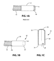
FIG. 1A is a perspective view of a conventional cable bolt button;
FIG. 1B is a perspective view of one embodiment of a cable bolt button according to the present invention;
FIG. 1C is a cross-sectional view of the cable bolt button shown in FIG. 1B;
FIG. 2 is a cross-sectional view of a second embodiment of a cable bolt button according to the present invention having protrusions and a cavity;
FIG. 3 is a perspective view of a third embodiment of a cable bolt button according to the present invention having a sidewall with a non-linear profile;
FIG. 4 is a perspective view of a fourth embodiment of a cable bolt button according to the present invention;
FIG. 5A is a perspective view of a fifth embodiment of cable bolt button according to the present invention;
FIG. 5B is a top view of the cable bolt button shown in FIG. 5A;
FIG. 6A is a side view of a sixth embodiment of a cable bolt button according to the present invention;
FIG. 6B is a top view of the cable bolt button shown in FIG. 6A;
FIG. 7A is a side view of a seventh embodiment of a cable bolt button according to the present invention;
FIG. 7B is a top view of the cable bolt button shown in FIG. 7A;
FIG. 7C is a top view of an eighth embodiment of a cable bolt button according to the present invention;
FIG. 8 is a cross-section view of a cable bolt button on a cable bolt engaging a resin cartridge in a bore hole.
DETAILED DESCRIPTION OF THE INVENTION
A prior art cable bolt button is shown in FIG. 1A and one embodiment of a cable bolt button 10, according to the present invention, is shown in FIGS. 1B and 1C. The prior art cable bolt button comprises a metal conduit 12 crimped around the cable bolt 14. The distal end 16 of the cable bolt 14 may be exposed and extends beyond the end 18 of metal conduit 12.
The cable bolt button 10 of the present invention comprises a cylindrical continuous sidewall 20 having a first end 22 and a second end 24 and an end portion 26. The end portion 26 is attached about its periphery to, or is continuous with the first end 22 of the continuous sidewall 20, thereby creating an inner cavity 28. The end portion 26 may have a generally convex shape. The end portion 26 may be formed integrally with the sidewall 20 using a molding process or other suitable technique, or may be bonded to the sidewall 20 using adhesive or any other suitable method. In use, the distal end 16 of the cable bolt 14 is received within the inner cavity 28. The cable bolt button 10 forms an interference fit between an interior surface of the sidewall 20 of the cable bolt button 10 and the cable bolt 14. The inner cavity 28 may be about 0.5″-0.7″ in diameter. The end portion 26 prevents the cable bolt button 10 from sliding down the cable bolt 14 when the distal end 16 of the cable bolt 14 is inserted into a bore hole. The end portion 26 may be continuous and fully enclose the first end 22 or may be discontinuous (having opening(s) therethrough) yet still prevent distal end 16 of cable bolt 14 from passing first end 22 of cable bolt button 10.
The sidewall 20 of the cable bolt button 10 generally extends a sufficient distance along the cable bolt 14 to contain all of the individual strands of the cable bolt 14 and create a tight interference fit between the sidewall 20 and the cable bolt 14. The sidewall may be about 1.5″ in length or more.
While cable bolt button 10 has a sidewall 20 with a circular cross-section and a circular, convex end portion 26, these parameters may be varied. The cross-section of sidewall 20 may have any shape as long as the sidewall 20 of the cable bolt button and the cable bolt 14 fit together when the cable bolt button is placed on the distal end 16 of the cable bolt 14.
The end portion 26 may be attached such that its periphery is flush with the sidewall 20 as shown in FIGS. 1B and 1C or may extend beyond the sidewall 20 (not shown). Where the end portion 26 is flush with the sidewall 20, the end portion 26 may take a shape corresponding to the shape of the cross-section of the sidewall 20 in order to close the first end of the sidewall 20. Where the end portion 26 extends beyond the sidewall 20, it may take any shape. The end portion 26 may also be flat, convex, concave, or as described later, may comprise a plurality of intersecting surfaces that form protrusions and recesses.
As shown in FIG. 2, in another embodiment, cable bolt button 100 includes an end portion 126 having at least one protrusion 130 extending outwardly away from an inner cavity 128. The protrusions 130 may be integral with the end portion 126 or may be attached to the end portion 126 using adhesive or any other suitable means. The protrusions 130 may be configured to receive an end of a resin cartridge and/or to align a resin cartridge on a cable bolt. The protrusions 130 may also assist in ripping open a resin cartridge and mixing the resin.
The end portion 126 may define at least one recess 132. The recess 132 may be defined in the center of the end portion 126 to receive an end of a resin cartridge and/or to center the cable bolt with the resin cartridge. However, any number of recesses may be used.
As shown in FIG. 3, in another embodiment, cable bolt button 200 includes a sidewall 220 with a first end 222 having a non-linear, scalloped profile with concave portions 234 and convex portions 236. An end portion 226 follows this profile, having a generally smooth concave shape sloping inwardly from the first end 222 of sidewall 220 such that the deepest portion 237 of the end portion 226 is at the center, with protrusions 230 and recesses 232 extending therebetween.
It should be appreciated that the protrusions and recesses formed in the end portion 226 of cable bolt button 200 may be further modified or increased in number. This may be achieved, for example, by defining a plurality of additional intersecting surfaces forming the contours of the protrusions 230 and recesses 232. These surfaces may be flat, convex, or concave.
In one such embodiment, cable bolt button 300 (FIG. 4) includes ridges 338 extending from a top 340 of each protrusion 330 to a center region 342 of an end portion 326. Generally concave triangular-shaped surfaces 344 are bounded by first end 322 of sidewall 320 and ridges 338. It should be appreciated that the intersecting surfaces of end portion 326 may vary in size, shape, number, and orientation to further define the protrusions and recesses.
In another embodiment, shown in FIGS. 5A and 5B, the cable bolt button 400 may have a distinct shape in order to center the cable bolt with the resin cartridge and assist in ripping open the resin cartridge and mixing the resin.
Cable bolt button 400 includes a sidewall 420 having a first end 422 that is scalloped with four concave portions 434 and four convex portions 436 bounded by edge surface 423. An end portion 426 follows the contour of the first end 422 of the sidewall 420, as in cable bolt buttons 200 and 300. End portion 426 includes a central concave surface 446. The central concave surface 446 may be four-sided and generally square-shaped. The central concave surface 446 is bound on all sides by inside lip portions 450 adjoined by corner portions 448.
Protrusions 430 are formed where the end portion 426 adjoins the convex portions 436 of the first end 422 of the sidewall 420. Each protrusion 430 has a top portion 440 and multiple side surfaces 440 a, 440 b, 440 c. Side surfaces 440 a, 440 b, 440 c may alternatively be a single surface or two or more surfaces. Corner portions 448 connect with protrusion 430 via surfaces 452, thereby defining surfaces 454.
The intersecting surfaces of cable bolt button 400 form five concave recesses 454 and 446 and four prong-shaped protrusions 430. The end portion 426 may be integral with one or more of the sidewall 420 and edge surface 423. One embodiment of cable bolt button 400 is about 1.5″ in length as measured from an open second end 460 of the sidewall 420 to the bottom of the concave portion 434 and about 1.8″ in length as measured from the open second end 460 of the sidewall 420 to the top of the convex portion 436.
In another embodiment, shown in FIGS. 6A and 6B, cable bolt button 500 is similar to cable bolt button 400, except as noted herein. Cable bolt button 500 includes protrusions 530 having top portion 540 and side surfaces 540 a, 540 b, 540 c, 540 d, 540 e, and 540 f connecting via surface 552 to corner portion 448.
In yet another embodiment, shown in FIGS. 7A and 7B, cable bolt button 600 is similar to cable bolt button 400, except as noted herein. Protrusions 630 and edge surface 623 surround end portion 626. While end portion 426 of cable bolt button 400 is generally concave, end portion 626 is generally convex as shown in phantom in FIG. 7A. End portion 626 includes surfaces 652 extending from protrusions 630 and terminating at apex 656 which may be lower than top portions 640 of protrusions 630. Alternatively, as shown for cable bolt button 600′ in FIG. 7C, protrusions 730 with multiple side surfaces 740 a-740 f (akin to side surfaces 540 a-540 f of protrusions 530 of cable bolt 500) may be included.
FIG. 8 shows cable bolt button 400 installed on the distal end of a cable bolt 66 being inserted into bore hole 68 and illustrates how cable bolt button 400 engages the end closure 70 of the resin cartridge 72. This centers the cable bolt button 400 with the resin cartridge 72 which allows for more effective puncturing of the cartridge and mixing of the resin. It also reduces finger gloving. The protrusions and recesses in the cable bolt button 400 also contribute to more effective mixing of the resin. Cable bolt buttons 100, 200, 300, 500, 600, and 600′ may also be used in a similar manner to achieve the same desirable results. The present invention may be used in place of conventional metal buttons, thereby providing cost savings in the production of cable bolts.
The cable bolt buttons, 100-600′ may be made of plastic, such as a flexible, non-brittle plastic that can withstand insertion of the cable bolt into the bore hole without fracturing. One suitable material is poly vinyl chloride (PVC). Buttons 100-600′ may be provided by molding or other conventional plastics processing techniques.
While the present invention has been described with reference to particular embodiments of a mine roof bolt and methods associated therewith, those skilled in the art may make modifications and alterations to the present invention without departing from the spirit and scope of the invention. Accordingly, the foregoing detailed description is intended to be illustrative rather than restrictive. The invention is defined by the appended claims, and all changes to the invention that fall within the meaning and the range of equivalency of the claims are embraced within their scope.

Claims (15)

The invention claimed is:
1. A cable bolt button comprising:
a sidewall having a first end and a second end and an end portion connected to said sidewall at said first end;
said sidewall and end portion defining an inner cavity for receiving a distal end of a cable bolt;
wherein, there is an interference fit between said sidewall of said cable bolt button and said cable bolt when said cable bolt button is placed over said distal end of said cable bolt;
wherein said sidewall and said end portion of said cable bolt button are made of a flexible material;
wherein at least a portion of said end portion of said cable bolt button contacts an end of a resin cartridge when said cable bolt is placed in a mine bore; and
wherein a portion of said first end of said sidewall of said cable bolt button extends outwardly away from the inner cavity relative to another portion of said first end of said sidewall.
2. The cable bolt button of claim 1, wherein the end portion completely closes the first end of the sidewall.
3. The cable bolt button of claim 1, wherein the end portion does not completely close the first end of the side wall, but sufficiently covers said distal end of said cable bolt when said cable bolt button is placed over said distal end of said cable bolt to keep said cable bolt button from sliding down said cable bolt.
4. The cable bolt button of claim 1, wherein the end portion is one of concave, convex, or flat.
5. The cable bolt button of claim 1, wherein the end portion further comprises a plurality of intersecting surfaces that form protrusions and recesses.
6. The cable bolt button of claim 5, wherein each surface is one of flat, concave, or convex.
7. The cable bolt button of claim 1 made of flexible plastic.
8. The cable bolt button of claim 1 made of poly vinyl chloride.
9. The cable bolt button of claim 1, wherein a profile of said first end of said sidewall is nonlinear and a periphery of said end portion follows said profile of said sidewall.
10. The cable bolt button of claim 9, wherein the profile of the sidewall is scalloped.
11. The cable bolt button of claim 9, wherein the end portion further comprises a plurality of intersecting surfaces that form protrusions and recesses.
12. The cable bolt button of claim 11, wherein each surface is one of flat, concave, or convex.
13. A cable bolt button comprising:
a sidewall having a first end and a second end and an end portion connected to said sidewall at said first end;
said sidewall and end portion defining an inner cavity for receiving a distal end of a cable bolt;
wherein, there is an interference fit between said sidewall of said cable bolt button and said cable bolt when said cable bolt button is placed over said distal end of said cable bolt;
wherein at least a portion of said end portion of said cable bolt button contacts an end of a resin cartridge when said cable bolt is placed in a mine bore; and
wherein at least one protrusion extends from the end portion outwardly away from the inner cavity.
14. The cable bolt button of claim 13, wherein the end portion further comprises at least one recess.
15. A cable bolt button comprising:
a sidewall having a first end and a second end and an end portion connected to said sidewall at said first end;
said sidewall and end portion defining an inner cavity for receiving a distal end of a cable bolt;
wherein, there is an interference fit between said sidewall of said cable bolt button and said cable bolt when said cable bolt button is placed over said distal end of said cable bolt;
wherein said sidewall and said end portion of said cable bolt button are made of a flexible material;
wherein at least a portion of said end portion of said cable bolt button contacts an end of a resin cartridge when said cable bolt is placed in a mine bore; and
wherein a portion of said end portion of said cable bolt button extends outwardly away from the inner cavity relative to a more centrally disposed portion of said end portion.
US13/008,095 2010-02-18 2011-01-18 Plastic cable bolt button Expired - Fee Related US8647020B2 (en)

Priority Applications (1)

Application Number Priority Date Filing Date Title
US13/008,095 US8647020B2 (en) 2010-02-18 2011-01-18 Plastic cable bolt button

Applications Claiming Priority (2)

Application Number Priority Date Filing Date Title
US30568610P 2010-02-18 2010-02-18
US13/008,095 US8647020B2 (en) 2010-02-18 2011-01-18 Plastic cable bolt button

Publications (2)

Publication Number Publication Date
US20110200400A1 US20110200400A1 (en) 2011-08-18
US8647020B2 true US8647020B2 (en) 2014-02-11

Family

ID=44369762

Family Applications (1)

Application Number Title Priority Date Filing Date
US13/008,095 Expired - Fee Related US8647020B2 (en) 2010-02-18 2011-01-18 Plastic cable bolt button

Country Status (1)

Country Link
US (1) US8647020B2 (en)

Citations (17)

* Cited by examiner, † Cited by third party
Publication number Priority date Publication date Assignee Title
US3077809A (en) * 1958-05-28 1963-02-19 British Ropes Ltd Roof bolt with a flexible tension member and cup-shaped expansible securing means
US5288176A (en) * 1993-03-01 1994-02-22 Scott Investment Partners Yielding grout compactor for mine roof support fixture
US5525013A (en) * 1994-10-31 1996-06-11 Seegmiller; Ben L. Cable bolt structure and related components
US5556233A (en) * 1993-12-23 1996-09-17 Rsc Mining (Proprietary) Limited Rock anchor assembly
US5584608A (en) * 1994-07-05 1996-12-17 Gillespie; Harvey D. Anchored cable sling system
US5624212A (en) * 1994-07-05 1997-04-29 Gillespie; Harvey D. Anchored cable sling system
US5829922A (en) 1996-01-11 1998-11-03 Jenmar Corporation Cable bolt head
US5919006A (en) 1997-02-14 1999-07-06 Jennmar Corporation Tensionable cable bolt with mixing assembly
US5931064A (en) * 1998-07-13 1999-08-03 Gillespie; Harvey D. Cable insertion tool
US6270290B1 (en) 1997-02-14 2001-08-07 Jennmar Corporation Tensionable cable bolt
US6402433B1 (en) * 2000-07-25 2002-06-11 H. Doug Gillespie Tensionable mine roof bolt
US6428243B1 (en) * 1996-09-09 2002-08-06 Quantax Pty Ltd Cable bolt
US6527482B1 (en) 1999-09-14 2003-03-04 Jennmar Corporation Grit surface cable products
US6612783B2 (en) * 2001-02-09 2003-09-02 Jennmar Corporation Cable bolt with mixing delay device
US6622783B2 (en) 2001-08-14 2003-09-23 Modine Manufacturing Company Self-fixturing fan shroud
US20090041550A1 (en) * 2007-08-07 2009-02-12 Jennmar Corporation Expansion bail anchor and method
US20090067932A1 (en) * 2005-12-02 2009-03-12 Fox William G Re-tensionable cable bolt apparatus and related method

Patent Citations (20)

* Cited by examiner, † Cited by third party
Publication number Priority date Publication date Assignee Title
US3077809A (en) * 1958-05-28 1963-02-19 British Ropes Ltd Roof bolt with a flexible tension member and cup-shaped expansible securing means
US5288176A (en) * 1993-03-01 1994-02-22 Scott Investment Partners Yielding grout compactor for mine roof support fixture
US5556233A (en) * 1993-12-23 1996-09-17 Rsc Mining (Proprietary) Limited Rock anchor assembly
US5584608A (en) * 1994-07-05 1996-12-17 Gillespie; Harvey D. Anchored cable sling system
US5624212A (en) * 1994-07-05 1997-04-29 Gillespie; Harvey D. Anchored cable sling system
US5525013A (en) * 1994-10-31 1996-06-11 Seegmiller; Ben L. Cable bolt structure and related components
US5829922A (en) 1996-01-11 1998-11-03 Jenmar Corporation Cable bolt head
US6322290B1 (en) 1996-01-11 2001-11-27 Jennmar Corporation Cable bolt head
US6056482A (en) 1996-01-11 2000-05-02 Jennmar Corporation Cable bolt head
US6428243B1 (en) * 1996-09-09 2002-08-06 Quantax Pty Ltd Cable bolt
US6074134A (en) 1997-02-14 2000-06-13 Jennmar Corporation Tensionable cable bolt
US6270290B1 (en) 1997-02-14 2001-08-07 Jennmar Corporation Tensionable cable bolt
US5919006A (en) 1997-02-14 1999-07-06 Jennmar Corporation Tensionable cable bolt with mixing assembly
US5931064A (en) * 1998-07-13 1999-08-03 Gillespie; Harvey D. Cable insertion tool
US6527482B1 (en) 1999-09-14 2003-03-04 Jennmar Corporation Grit surface cable products
US6402433B1 (en) * 2000-07-25 2002-06-11 H. Doug Gillespie Tensionable mine roof bolt
US6612783B2 (en) * 2001-02-09 2003-09-02 Jennmar Corporation Cable bolt with mixing delay device
US6622783B2 (en) 2001-08-14 2003-09-23 Modine Manufacturing Company Self-fixturing fan shroud
US20090067932A1 (en) * 2005-12-02 2009-03-12 Fox William G Re-tensionable cable bolt apparatus and related method
US20090041550A1 (en) * 2007-08-07 2009-02-12 Jennmar Corporation Expansion bail anchor and method

Also Published As

Publication number Publication date
US20110200400A1 (en) 2011-08-18

Similar Documents

Publication Publication Date Title
US9303672B2 (en) Rivet fastener
RU2463175C2 (en) Securing cord to be used with sealing for window sealing
AU2015324628B2 (en) A floating unit and a floating structure assembled from such floating units
CN106163937A (en) Tamper opening
CN108602420A (en) Method of the manufacture for the seal assembly of vehicle
CN205706117U (en) The seal member of arrangements for automotive doors
EP1707066A1 (en) Sealing slide fastener with teeth welded onto the tapes which they join
US8647020B2 (en) Plastic cable bolt button
US9850049B2 (en) Flexible wire tie
RU2378470C1 (en) Shut-locking device "лавр-с3"
USD600329S1 (en) Ring for sealing
CN105064164B (en) One kind is permeable to enclose tree brick
US8075187B2 (en) Closure kit for a bag comprising means preventing a cursor from being torn off and fitted bag
CN108973620A (en) Car roof stringer and seal system
CN104000352B (en) Dismountable self-locking zipper slider
CN106723694A (en) A kind of compound buckle-type round key ring
CN209410758U (en) A kind of battery strapping
CN207312691U (en) Locking member and interlocking block part system
CN207022898U (en) Pet latches
US8959673B2 (en) Multi-purpose beading for swimming pool liners
JP3161400U (en) Protective cap for metal connection
CN215513519U (en) Square sealing plug
CN209410759U (en) A kind of strapping
JP5938055B2 (en) Side visor molding, its mounting structure, and automotive side visor having this molding
CN106467207B (en) The case lid articulated part of storage box

Legal Events

Date Code Title Description
AS Assignment

Owner name: FCI HOLDINGS DELAWARE, INC., PENNSYLVANIA

Free format text: ASSIGNMENT OF ASSIGNORS INTEREST;ASSIGNORS:STANKUS, JOHN C.;FAULKNER, DAKOTA;FEYRER, JOHN;AND OTHERS;SIGNING DATES FROM 20101214 TO 20101223;REEL/FRAME:025651/0262

AS Assignment

Owner name: WELLS FARGO BANK, NATIONAL ASSOCIATION, NEW YORK

Free format text: SECURITY AGREEMENT;ASSIGNORS:DSI UNDERGROUND SYSTEMS, LLC;FCI HOLDINGS DELAWARE, INC., A DELAWARE CORPORATION;J-LOK CO., A PENNSYLVANIA CORPORATION;REEL/FRAME:038179/0591

Effective date: 20160229

FEPP Fee payment procedure

Free format text: MAINTENANCE FEE REMINDER MAILED (ORIGINAL EVENT CODE: REM.)

LAPS Lapse for failure to pay maintenance fees

Free format text: PATENT EXPIRED FOR FAILURE TO PAY MAINTENANCE FEES (ORIGINAL EVENT CODE: EXP.)

STCH Information on status: patent discontinuation

Free format text: PATENT EXPIRED DUE TO NONPAYMENT OF MAINTENANCE FEES UNDER 37 CFR 1.362

FP Lapsed due to failure to pay maintenance fee

Effective date: 20180211