US8649594B1 - Active and adaptive intelligent video surveillance system - Google Patents
Active and adaptive intelligent video surveillance system Download PDFInfo
- Publication number
- US8649594B1 US8649594B1 US12/802,265 US80226510A US8649594B1 US 8649594 B1 US8649594 B1 US 8649594B1 US 80226510 A US80226510 A US 80226510A US 8649594 B1 US8649594 B1 US 8649594B1
- Authority
- US
- United States
- Prior art keywords
- event
- classifier
- classifiers
- events
- surveillance system
- Prior art date
- Legal status (The legal status is an assumption and is not a legal conclusion. Google has not performed a legal analysis and makes no representation as to the accuracy of the status listed.)
- Active, expires
Links
Images


Classifications
-
- G—PHYSICS
- G06—COMPUTING; CALCULATING OR COUNTING
- G06V—IMAGE OR VIDEO RECOGNITION OR UNDERSTANDING
- G06V10/00—Arrangements for image or video recognition or understanding
- G06V10/70—Arrangements for image or video recognition or understanding using pattern recognition or machine learning
- G06V10/77—Processing image or video features in feature spaces; using data integration or data reduction, e.g. principal component analysis [PCA] or independent component analysis [ICA] or self-organising maps [SOM]; Blind source separation
- G06V10/778—Active pattern-learning, e.g. online learning of image or video features
- G06V10/7784—Active pattern-learning, e.g. online learning of image or video features based on feedback from supervisors
-
- G—PHYSICS
- G06—COMPUTING; CALCULATING OR COUNTING
- G06F—ELECTRIC DIGITAL DATA PROCESSING
- G06F18/00—Pattern recognition
- G06F18/20—Analysing
- G06F18/21—Design or setup of recognition systems or techniques; Extraction of features in feature space; Blind source separation
- G06F18/217—Validation; Performance evaluation; Active pattern learning techniques
- G06F18/2178—Validation; Performance evaluation; Active pattern learning techniques based on feedback of a supervisor
-
- G—PHYSICS
- G06—COMPUTING; CALCULATING OR COUNTING
- G06V—IMAGE OR VIDEO RECOGNITION OR UNDERSTANDING
- G06V20/00—Scenes; Scene-specific elements
- G06V20/50—Context or environment of the image
- G06V20/52—Surveillance or monitoring of activities, e.g. for recognising suspicious objects
Definitions
- Embodiments of present invention relate to an intelligent surveillance system. More specifically, embodiments of the present invention relate to systems that use video and other sensor inputs where monitoring is performed automatically by a computer system.
- a first set of video processing algorithms is used to detect, track, and classify objects while a second set of algorithms is used to infer the events based on the temporal and spatial information of the objects and preset rules.
- the algorithms developed have very limited ability to adapt to new and unseen environments.
- auto-adaptation techniques that were available did not adapt well to active surveillance systems.
- background modeling algorithms in the systems made adaptations when the background changed.
- the goal of these adaptations was only to determine the change in the scene. The definition of the change was fixed and non-adapting.
- Other types of auto-adaptation techniques such as ground plane calibration did not improve the intelligence of the system over time, as they did not accumulate knowledge.
- FIG. 1 is a block diagram of a surveillance system according to an exemplary embodiment of the present invention.
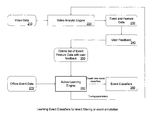
- FIG. 2 is a flow diagram illustrating the work flow of a surveillance system according to an embodiment of the present invention.
- FIG. 3 illustrates a framework of a rule based classification procedure according to an exemplary embodiment of the present invention.
- FIG. 4 illustrates the framework of the human classification rule.
- FIG. 5 illustrates results obtained by a human detector according to an embodiment of the present invention.
- FIG. 6 illustrates leg detection examples according to an embodiment of the present invention
- FIG. 7 illustrates a size calibration classifier according to an embodiment of the present invention.
- FIG. 8 illustrates examples showing regions of objects and their corresponding annular regions for histogram matching according to an embodiment of the present invention.
- FIG. 9 illustrates a correlation map of the two examples shown in FIG. 8 according to an embodiment of the present invention.
- FIG. 10 illustrates a trajectory example of a vehicle object and a noise object according to an exemplary embodiment of the present invention.
- FIG. 11 illustrates a block diagram of an active learning engine 1100 according to an exemplary embodiment of the present invention.
- FIG. 12 is a flow chart illustrating classifier training according to an exemplary embodiment of the present invention.
- FIG. 13 illustrates a detailed implementation of the classifier training procedure illustrated in FIG. 12 .
- FIG. 14 illustrates a detailed implementation of ensemble classifier learning.
- FIG. 15 illustrates four prototype templates of the rectangular Haar wavelet like features on the left.
- FIG. 16 illustrates examples of a 3 ⁇ 3 kernel and Local Binary Pattern extraction according to an embodiment of the present invention.
- FIG. 17 illustrates a pseudo code implementation of an ECV learning scheme.
- FIG. 18 illustrates a pseudo code implementation of a function which computes ECV classification error.
- FIG. 19 is a flow chart illustrating a classifier tuning procedure according to an embodiment of the present invention.
- FIG. 20 illustrates a procedure for tuning thresholds for event classifiers according to an embodiment of the present invention.
- FIG. 21 illustrates a tuning procedure according to an alternative embodiment of the present invention.
- FIG. 22 is a flow chart illustrating a method for performing score mapping according to an embodiment of the present invention.
- FIG. 23 is a block diagram of a computer system implementing the surveillance system according to an embodiment of the present invention.
- An important characteristic in a successful intelligent video surveillance system is the ease in which the system can be adjusted for optimal performance in each specific site installation.
- the complexity of real world environments and scenarios post tremendous challenges for an intelligent system to have applications general enough for mass deployment.
- the intelligence of a passive conventional system is fixed after the installation, and will not improve its performance over time.
- Such a system is difficult to scale up.
- An active intelligent system is disclosed that has the ability to improve the knowledge and the intelligence of the system and adapt to new environments without requiring professional user involvement.
- an active system is disclosed that relieves the user from learning the complex system parameters and adjusting the system during an installation.
- the active system is capable of automatically improving the performance of system after installation.
- Embodiments of the present invention also give the system integrator more flexibility to deploy the system at different sites.
- the complexity of the system is made manageable by limiting the focus of the system to one or more specific environments and dramatically reducing the data space required to be processed.
- the performance of the system disclosed may be measured by the accuracy of the system.
- the accuracy of the system may be based on the accuracy of detection of events, the accuracy of certain statistics of scenes, and the accuracy of other attributes that is generated by the system.
- the accuracy of event detection can be measured by miss and false detection rates.
- the statistics may include a count of people, crowd density, traffic congestion status, and other parameters.
- mechanisms are disclosed that actively and automatically tune an intelligent video surveillance system to achieve high performance after the system is installed.
- the system also utilizes off-line data from outside the installed environment to tune the system so it is able to detect and classify events that may be found in other environments.
- the system will be able to maintain a default (“average”) performance while improving its accuracy at its installed environment.
- FIG. 1 is a block diagram of a surveillance system 100 according to an exemplary embodiment of the present invention.
- the surveillance system 100 may be performed by a computer system executing sequences of instructions represented by the modules shown in FIG. 1 . Execution of the sequences of instructions causes the computer system to support an active and adaptive intelligent video surveillance system as will be described hereafter.
- hard-wire circuitry may be used in place of or in combination with software instructions to implement the present invention.
- the present invention is not limited to any specific combination of hardware circuitry and software.
- the surveillance system 100 includes a surveillance system manager 110 .
- the surveillance system manager 110 is connected to and transmits data between the components of the surveillance system 100 .
- Block 120 represents a video analytics engine.
- the video analytics engine 120 receives video from one or more cameras (not shown) in the surveillance system 100 .
- the video analytics engine 120 generates an on-line data set from the video data.
- the on-line data set may include events and feature data.
- An event may include an image of an event that occurred and the feature data may be one or more numeric values that represents features of the event.
- the feature data may provide an indication of the likelihood that an event that occurred matches an event being monitored by the surveillance system.
- Each event detected by the surveillance system 100 may have specific feature data associated with it.
- a human intrusion event may have feature data generated by a human intrusion detection algorithm that tracks specific features of a human being.
- An unattended object event may have feature data generated by an algorithm that tracks the appearance of the object and how stable the object is.
- the feature data for events that are monitored may be used by the surveillance system to improve its accuracy.
- Block 130 represents a feedback collection engine.
- the feedback collection engine 130 collects feedback about events or other attributes of the surveillance system.
- the feedback collection engine 130 may present the event to a user and solicit a response from the user as to whether the event is a true or false event that matches or does not match an event being monitored.
- annotation labels may be provided by a user to help create specific event classifiers.
- the feedback collection engine 130 may also or alternatively collect feedback from another detection module running in parallel in the surveillance system that has a different detection capability or collect feedback using a different algorithm for assessing the likelihood that the event that occurred matches the event being monitored. For example, a human detector based tracking algorithm may be used together with a foreground object based motion tracking algorithm. The differences detected can be used to provide feedback to one another since their false detections are usually very different. Feedback provides a way to improve the default detection rate.
- Block 140 represents an active learning engine 140 .
- the active learning engine 140 may be invoked automatically or manually by a user. According to an embodiment of the present invention, the active learning engine 140 may be invoked when a number of false events detected exceeds a predetermined threshold value.
- the active learning engine 140 may use on-line feature data and feedback to generate event classifiers that can be used for classifying the events detected.
- the event classifier may operate as a filter to filter out unwanted events that are determined not to match the event to be monitored. Alternatively, the event classifier may operate as a sorter to sort, classify, and label the event that occurred into one of many types of events that are being monitored.
- the active learning engine 140 may also use off-line feature data from an off-line data set.
- a large off-line data set may be used along with the on-line data set to generate a filter.
- the off-line data may include a large sample data set of possible true event feature data, and/or model data that represents a default average detection system.
- the use of off-line data may be helpful in calibrating and tuning a system since the number of true events in an on-line data set may be small. In some instances it may not be possible for the active learning engine 140 to formulate the characteristics of the true events in one specific environment by using on-line data alone.
- the use of off-line data will ensure that the surveillance system 100 maintains average performance for those true events that have not been seen but improve the accuracy by using the events that have been seen.
- the off-line data set may include representative positive samples of humans and vehicles. This offline data serves to provide the surveillance system with a broad sampling of information.
- the event classifier generated by the active learning engine 140 may be applied to each event generated and a confidence score may be calculated by running the event classifier for the event. The score may be used to determine if the event is wanted or not.
- the active learning engine 140 produces an event classifier with a default threshold that has a fixed expectation miss rate and a maximized false event reduction rate.
- the active learning engine may create an event classifier operating as a filter that aims to achieve a miss rate of less than 5%.
- all scores are normalized and aligned and one threshold can be applied to all filters.
- the user may set different thresholds for different zones monitored by the surveillance system 100 . In this embodiment, zones where security is more important may have score thresholds set lower. Zones where security is less important may have score thresholds set higher.
- the event classifiers created by the active learning engine 140 may be created for one camera or any number of cameras.
- the event classifiers may be applied or not applied to video data originating from one or more specific cameras.
- user may also specify what type of data from an on-line data set is to be used to generate an event classifier. For example, a user may specify that on-line data set data generated from video data from one camera, but not from another camera may be used to generate a specific event classifier.
- events processed by an event classifier such as filtered events remain in the system and a user may choose to display them and provide feedback to miss detections to improve the detection rate the next time the active learning engine 140 is invoked.
- the active learning engine 140 can also generate receiver operating characteristic (ROC) curves to provide a user with the expected miss and false rate for any threshold chosen.
- ROC receiver operating characteristic
- the confidence score may be displayed with the event and the event list may be sorted by the confidence score.
- the event classifiers can be generated based on annotation labels. This allows events to be easily retrieved based on their annotation labels and scores. For example, a dog annotation event classifier may be created for all intrusion events caused by dogs. The event may be annotated as “dog” if the system decides that the event is likely caused by a dog. Such an annotation capability provides additional flexibility for the user to manage the large amounts of events process by the surveillance system 100 . According to an embodiment of the surveillance system 100 , the generated event classifiers are stored along with the details describing the event classifiers and their attributes. The event classifiers are managed, and can be manually or automatically applied to detection instances.
- the surveillance system manager 110 may apply the event classifiers to new on-line data sets generated by the video analytics engine to allow the surveillance system 100 to more accurately process video data. This would allow the surveillance system 100 to improve its detection and/or classification of events being monitored.
- FIG. 2 is a flow diagram illustrating the work flow of a surveillance system according to an embodiment of the present invention.
- a video analytic engine 220 receives on-line video data 210 originating from one or more video cameras in the surveillance system.
- the video analytic engine 220 generates events of interest along with feature data 230 .
- the feedback collection engine 240 presents the events to a user and solicits the user's feedback regarding whether the events match events that are being monitored by the surveillance system.
- the on-line set of events and feature data and user feedback 250 are provided to an active learning engine 260 .
- Also provided to the active learning engine is offline event data 270 which includes off-line feature data.
- the feature data and feedback will then be used by the active learning engine to create event classifiers 280 .
- the event classifiers generated by the active learning engine 260 may be used as tuning parameters for the video analytic engine 220 .
- the video analytic engine uses a rule based classification (RBC) procedure to classify events and generate feature data.
- RBC rule based classification
- the RBC procedure may follow the framework illustrated in FIG. 3 according to an embodiment of the present invention, and be an ensemble of four novel classification rules, the human classification rule, vehicle classification rule, saliency classification rule, and trajectory classification rule.
- the RBC procedure may classify events into one of four categories: Human, Vehicle, Objects, and Noise.
- the category of Object includes any objects other than Human, Vehicle, and Noise.
- the event feature data of the perimeter intrusion includes the features created by the RBC procedure and an image of the object that is detected.
- the four classification rules are described as follows.
- FIG. 4 illustrates the framework of the human classification rule according to an embodiment of the present invention.
- the human classification rule includes three independent components, a human upper body detector 401 , a human leg detector 402 , and a human height calibrator 403 .
- FIG. 5 illustrates results obtained by the human detector according to an embodiment of the present invention.
- the output of the component denoted as H d , is the sum of the detect scores on the input object image.
- the bounding boxes have been extended to cover the entire human bodies.
- the leg detector first extracts the curvilinear structure of the object from the input image by using line detection. Then the leg-like line features are detected from the curvilinear structure. For example, from some prior knowledge, it is known that the leg line candidates most likely appear in the lower half of the object and has approximately vertical directions in most surveillance scenarios.
- FIG. 6 illustrates leg detection examples where the top lists the extracted curvilinear structures by applying the line detection to the foreground images of the input objects and the bottom is the detected leg lines according to an embodiment of the present invention.
- a leg detection score denoted as H 1 can be obtained by matching the detected leg-like line features with pre-saved leg templates.
- the human height calibrator compares the pixel height of an object detected in the image plane with that of a real average person at the same location, and outputs a score according to their consistency.
- 0 ⁇ a ⁇ b are parameters learned from examples. It can be seen that a bigger H c value indicates a higher probability for the input object to have a human-like size.
- the final human score can be obtained by fusion of the outputs of the three individual components using the score mapping function, f a,b (x) from relationship (31) and is shown below.
- H f ( w d ⁇ f a d ,b d ( H d )+(1 ⁇ w d ) ⁇ f a l ,b l ( H l )) ⁇ (1 ⁇ w c )+ H c ⁇ w c (2)
- w d ⁇ [0, 1] and w c ⁇ [0, 1] are regularization parameters to balance the significance of the three component scores, and they can be learned from a set of training samples by a linear regression model.
- the vehicle classification rule recognizes a vehicle object. It is an ensemble classifier that includes two independent classifiers, an edge direction histogram (EDH) based classifier, and a size calibration classifier which is illustrated in FIG. 7 according to embodiment of the present invention.
- EDH edge direction histogram
- B e be a normalized edge direction histogram built from the input image of an object.
- the normalized edge direction B e can be considered an N ⁇ 1 vector, where N is the number of bins in the histogram covering angles from 0 to 180 degrees.
- the EDH-based classifier extracts the most discriminant feature basis, ⁇ , by learning a set of vehicle and non-vehicle (mostly human) samples with linear discriminant analysis (LDA).
- LDA linear discriminant analysis
- the vehicle size calibration classifier is similar to the one based on human height calibration. It recognizes a vehicle object by comparing the pixel size (area) of a detected object with that of a real average vehicle at the same image location. Let s i and s r denote the two sizes, respectively.
- V e w e ⁇ V e +(1 ⁇ w e ) ⁇ V c (4)
- CHMS Color Histogram Matching Score
- TMS Texture Matching Score
- X be the bounding box of an object
- a(X) be the annular region centered on the object X, but excluding X.
- FIG. 8 Two examples are shown in FIG. 8 .
- a and B are two moving objects detected by subtracting a background model.
- A is a real human
- B is a false object caused due to shadow moving.
- the CHMS feature of X, denoted as S C H M S (x), is calculated by the following relationship.
- FIG. 8 illustrates two examples to show regions of objects and their corresponding annular regions for histogram matching according to an embodiment of the present invention.
- an example shows peak and side lobe regions for PSR calculation.
- S C H M S (A) 0.23101
- S P SR (A) 3.788
- S C H M S (A) 0.50429
- S P SR (A) 1.7487
- FIG. 9 illustrates a correlation map of the two examples shown in FIG. 8 . On the left the real object A is shown. On the right, the false object B is shown.
- H x and H a(x) are two N 3 ⁇ 1 vectors representing the (R,G,B) color histograms of X and its annular region a(X), respectively, and N is the number of bins for each color channel.
- a region is defined that extends from and centered on the object X, e(X), which unlike a(X), includes X.
- a correlation map between e(X) and X is then obtained by the following relationship.
- C ( x,y ) ( I X I e(X) )( x,y ) (6)
- I X and I e(X) are the original images on the regions X and e(X), respectively, and denotes the convolution operator.
- FIG. 9 shows the correlation maps of the two examples of FIG. 8 .
- the peak sharpness can be quantified by the so-called “peak-to-sidelobe ratio” (PSR).
- C p and C s denote the means of C(x, y) on the peak and sidelobe regions as shown in FIG. 8 on the right.
- ⁇ s is the standard deviation of the sidelobe region.
- a background model is often used to detect foreground objects.
- I(x, y) we can also extract the CHMS and TMS features from an object and its corresponding background image, G(x, y).
- S I (X) and S G (X) obtained from I(x, y) and G(x, y), respectively.
- S G FS (X)/S I FS (X) for a real object tends to be much bigger compared to a noise object.
- a noise object usually exhibits a higher color similarity to its annular and background regions.
- f a s ,b s ( ⁇ ) and g a c ,b c ( ⁇ ) are the increasing and decreasing score mapping functions defined in relationships 31,32, respectively, and w s is a regularization parameter to tradeoff the significance of the correlation and histogram matching scores.
- w s is a regularization parameter to tradeoff the significance of the correlation and histogram matching scores.
- S f (X) value indicates a higher probability of being a true object.
- Motion trajectory has been shown to be a significant attribute in many pattern recognition tasks such as video object retrieval and human gesture recognition.
- a real object In video surveillance, a real object generally moves in a more continuous and smoother track compared to a noise object.
- the motion trajectories we can extract effective discriminant features to exclude noise objects or unwanted objected such as a swinging flag.
- a motion trajectory can be mathematically represented as a parametric curve (x(t),y(t)),t ⁇ [t 1 ,t 2 ] in the two-dimensional image plane. Since the raw trajectory is often noisy due to imperfect tracking, the trajectory is smoothed with a Gaussian low pass filter G ⁇ (t).
- c 0 (t) [ ⁇ circumflex over (x) ⁇ 0 (t), ⁇ 0 (t)] be the first derivative of ( ⁇ circumflex over (x) ⁇ (t), ⁇ (t)).
- the consistency of two neighboring points on the curve ( ⁇ circumflex over (x) ⁇ (t), ⁇ (t)) can be measured by the following.
- a smoothness feature can be derived from l(t) as shown below.
- T sm 1 ⁇ l ⁇ ( t 2 - t 1 ) ⁇ ⁇ t ⁇ l ⁇ ( t ) ( 12 )
- ⁇ l is the standard deviation of l(t),t ⁇ [t 1 ,t 2 ].
- the curvature is one of the important characteristics to describe a curve. It generally produces a higher curvature value for an irregular motion trajectory, which indicates a noise object for a high probability.
- the curvature feature of the curve ( ⁇ circumflex over (x) ⁇ (t), ⁇ (t)) can be computed with the following relationship.
- T cv 1 t 2 - t 1 ⁇ ⁇ t ⁇ ⁇ x ′ ⁇ ( t ) ⁇ y ′′ ⁇ ( t ) - x ′′ ⁇ ( t ) ⁇ y ′ ⁇ ( t ) ⁇ ( x ′2 ⁇ ( t ) + y ′2 ⁇ ( t ) ) 3 2 ( 13 )
- a trajectory score can be obtained by the fusion of the two smoothness and curvature features as shown with the relationship below.
- T f f a m ,b m ( T sm ) ⁇ g a v ,b v ( T cv ) (14)
- T f value represents a more flat and smooth curve, which is more likely to be the trajectory of a true object.
- FIG. 11 illustrates a block diagram of an active learning engine 1100 according to an exemplary embodiment of the present invention.
- the active learning engine 1100 may be used to implement the active learning engine 140 illustrated in FIG. 1 .
- the active learning engine 1100 may be used to automatically tune a surveillance system so that its operation improves for a specific environment and still maintains the quality of performance (average performance) for a general environment.
- the active learning engine 1100 achieves this by creating event classifiers using feedback, from users and/or other detection modules and/or other algorithms, and feature data associated with events or other system statistics, from on-line or off-line data sets.
- the active learning engine 1100 includes an active learning engine manager 1110 .
- the active learning engine manager 1110 is connected to and transmits data between the components of the active learning engine 1100 .
- the active learning engine 1100 includes a classifier training unit 1120 .
- the classifier training unit 1120 collects an on-line data set.
- the on-line data set may originate from video data from one or more video cameras on the surveillance system.
- the video data may be processed by a video analytic engine to include events and feature data.
- the classifier training unit 1120 may also collect feedback on the events from users or other detection modules or algorithms as well as collect an off-line data set.
- the active learning engine 1100 includes a classifier tuning unit 1130 .
- the classifier tuning unit 1130 operates to factor in an expected error detection objectives into the event classifier created.
- the active learning engine 1100 includes a classifier score alignment unit 1140 .
- the classifier score alignment unit 1140 performs a score normalization procedure on confidence scores of the event classifiers that maps outputs of different event classifiers to a common domain without compromising the performance of any individual event classifier.
- the common domain there is a same standard of measurement for all the event classifiers which allows for the results of the event classifiers to be compared.
- the event classifiers may be also be tuned to a single threshold
- FIG. 12 is a flow chart illustrating classifier training according to an exemplary embodiment of the present invention.
- the procedure illustrated in FIG. 12 may be performed by the classifier training unit 1120 to create an event classifier.
- training data is inputted.
- the training data may include the on-line and off-line data set and feedback collected.
- the training data is partitioned into groups.
- the training data is duplicated to K groups with different partitions.
- the partitions may follow a standard K-fold cross-validation method.
- Each group includes a training set and a validation set. There is no overlap between the two sets.
- ensemble classifier learning is performed.
- a classifier is trained with a classification error returned from previous iteration for each group.
- cross-validation performance evaluation is performed.
- the K classifiers obtained are applied to their corresponding K validation sets, respectively. Their classification errors are aggregated to obtain an overall error. The overall error is used by a learning stop criterion. The learning stops if the criterion is satisfied, and returns to 1203 with all the classification errors otherwise.
- FIG. 13 illustrates a detailed implementation of the classifier training procedure illustrated in FIG. 12 according to an embodiment of the present invention.
- FIG. 14 illustrates a detailed implementation of ensemble classifier learning according to an embodiment of the present invention.
- the procedure illustrated in FIG. 14 may be used to implement 1203 of FIG. 12 .
- an Adaboost-based learning procedure is implemented.
- a feature of this technique is its ability to reduce the amount of over fitting and the generalization error of classification, even as T becomes larger.
- the raw feature data in the on-line and off-line data sets may need to be further processed to create final features for classifier learning.
- a feature extraction procedure will use the images in the feature data to create additional features related to the images. Those image features may be general and are not behavior (or analytic engine) specific. In the example of event filtering for perimeter intrusion, there are three sets of features used.
- the first feature set is the RBC feature set ⁇ RBC.
- ⁇ RBC ⁇ H d , H l , H c , H f , V e , V c , V f , S CHMS G , S FS G , S PSR G , S CHMS I , S FS I , S PSR I , S f , T sm , T cv , T f ⁇ ( 15 )
- the second set of features includes the “Haar-like” features which have been proved to be very successful in many pattern recognition applications such as object detection.
- FIG. 15 illustrates four prototype templates of the rectangular Haar wavelet like features on the left according to an embodiment of the present invention.
- Each of the features takes a scalar value obtained by a linearly weighted combination of the pixel sums of the “positive” (light gray) and “negative” (dark gray) rectangles.
- the feature number is much larger than the dimensionality of the pattern, 768 , resulting in an over-complete set of scalar features.
- FIG. 15 illustrates an example of the most discriminant Haar-like feature found by AdaBoost learning for the human upper body pattern on the left.
- a third feature set comes from a “Local Binary Pattern” (LBP) (also referred to as a “Census Transform”).
- LBP Large Binary Pattern
- the LBP feature captures the local spatial structure of an image by binary comparisons of pixel intensities between a block A 0 and its eight surrounding blocks A 1 . . . A 8 in a 3 ⁇ 3 kernel depicted in FIG. 16 on the left. The result is grouped to form a binary string (LBP code) in a pre-defined order.
- the LBP feature corresponding to the block A 0 is the decimal form of the 8-bit binary string (a number ⁇ [0, 255]), which is invariant to monotonic gray-scale transformations.
- block A i is a single pixel. This feature is sensitive to noise and weak in capturing large or global spatial structure.
- a multi-scale LBP which extends A i to a n ⁇ n block from a single pixel is generated.
- the LBP-based features have been shown to be very successful in various pattern recognition applications. However, it can be seen that the illumination invariant effect is reached by weakening the contrast of locally neighboring pixels, which may include significant discriminant information for some object patterns.
- the Haar-like features may work well at this point. These two kinds of features may offer complementary information to each other in a joint learning framework. According to an embodiment of the present invention, Haar and LBP features may be introduced to capture additional discriminant information missed by the raw feature data, such as RBC features in perimeter intrusion case. Considering most samples that need to be filtered or need to be correctly classified are those previously failed, it is particularly important to have extra features, which are capable of extracting new significant discriminant information.
- both the Haar and LBP features can be computed very efficiently by an integral image or a summed-area table. It ensures the classifiers created with the two features to be able to work in real-time systems.
- a set of N labeled training examples is given as (x 1 ,y 1 ), . . . , (xN,yN), where yj ⁇ +1, ⁇ 1 ⁇ is the class label for the example xj ⁇ R n .
- a weak classifier h m (x) is a stump classifier associated with a single scalar feature f i . Thus, to find the best new weak classifier is equivalent to choosing the best corresponding scalar feature.
- a stronger classifier is a linear combination of the T weak classifiers as shown in the relationship below.
- ⁇ b is a threshold controlling the tradeoff of detect rate and false positive.
- the original form of h m (x) is a discrete function [10].
- the gentle AdaBoost is used to minimize the following weighted least square error.
- the optimal parameters of h m together with the best feature f* can be determined by minimizing the error of relationship (17).
- f * arg ⁇ ⁇ min f i ⁇ ⁇ ⁇ ⁇ E ⁇ ( f i ) ⁇ ( 25 )
- each iteration selects the best feature f* from the entire set, ⁇ . Since the set ⁇ includes several different feature sets ( ⁇ RBC, ⁇ Haar, ⁇ LBP ⁇ , one possible problem with such a procedure is that one kind of features is over-selected and that other features are ignored. This may dramatically increase the over fitting chance, particularly when the size of the on-line training sample (data set) is small. To avoid this problem, a feature sampling mechanism is introduced as illustrated in FIG. 14 . Let ⁇ 1 , ⁇ 2r , . . . , ⁇ n be n independent feature pools. In each iteration, a feature pool is randomly selected at a sampling rate of ⁇ 1 , ⁇ 2 , . .
- ⁇ ⁇ n corresponding to the n feature pools, respectively.
- ⁇ * be the selected feature pool.
- the best feature f* can be found by using the following relationship.
- the event classifier may be trained by using the learning procedure illustrated in FIG. 14 .
- the learning procedure involves two data sets.
- the first set is the on-line data set, denoted D, which is collected in a new installation environment.
- the second is the off-line set, denoted F, which is a generic data set that includes only positive patterns collected from environments outside the new installation environment.
- the off-line data set may be provided by the surveillance system developer and may cover other most representative variations of patterns.
- the purpose of introducing the off-line data set is to ensure the generalization ability of the event classifiers created.
- the parameters include 1) the number of weak classifiers T, and 2) the threshold of ensemble classifiers ⁇ . These are determined by examining the tradeoff between miss rate and false rate. According to an embodiment of the present invention, it is particularly important for the event classifiers to have a high detect rate to avoid missing detection of suspicious objects.
- the specific objective is a more difficult learning task than simply minimizing the overall error rate of the entire set. The former requires a more accurate estimate of the generalization error.
- a K fold ensemble cross-validation (ECV) learning scheme as shown in FIG. 13 is utilized.
- First a data partition procedure is conducted for the following ECV purposes.
- Each classifier could be learned by but not limited to the Adaboost-based training method as shown in FIG. 14 .
- AdaBoost the overall error of the K classifier ensemble H(T, ⁇ ) evaluated with individual component classifier H k (T, ⁇ ) on its corresponding validation set are used to determine the model parameters, i.e. the optimal weak classifier number T ⁇ and ensemble classifier threshold ⁇ ⁇ .
- the on-line sample number is often not comparable to the off-line one.
- FIG. 17 An exemplary implementation of the ECV learning scheme is shown in pseudo code in FIG. 17 .
- FIG. 18 illustrates a pseudo code implementation of the function Er(H, L), which computes the ECV classification error according to an embodiment of the present invention.
- FIG. 19 is a flow chart illustrating a classifier tuning procedure according to an embodiment of the present invention.
- the classifier tuning procedure illustrated in FIG. 19 may be implemented by the classifier tuning unit 1130 illustrated in FIG. 11 .
- the active learning engine 1100 may create several event classifiers for different video cameras or behaviors for its surveillance system.
- the threshold for each event classifier is typically different.
- the thresholds for the event classifiers may need to be tuned by the classifier score alignment unit 1140 .
- Tuning thresholds for event classifiers may be challenging as illustrated by the event classifier tuning procedure illustrated in FIG. 20 . It may also be challenging to compare results from different event classifiers since their outputs generally fall within different ranges.
- the classifier score alignment unit 1140 performs a score normalization procedure that maps outputs of different event classifiers to a common domain without compromising the performance of any individual event classifier.
- FIG. 21 illustrates a tuning procedure according to an exemplary embodiment of the present invention.
- the tuning procedure illustrated in FIG. 21 may be performed by the classifier score alignment unit 1140 (shown in FIG. 11 ).
- FIG. 22 is a flow chart illustrating a method for performing score mapping according to an embodiment of the present invention.
- the method illustrated in FIG. 22 may be performed by the classifier score alignment unit 1140 (shown in FIG. 11 ).
- H be a filter and X be the tuning data set to build the filter.
- a histogram h(y) may be built from Y.
- Let h + (y) and h ⁇ (y) denote histograms from positive and negative samples, respectively.
- K ⁇ 0 is a parameter to align thresholds of different filters.
- the score ⁇ (y) reflects the confidence of a filter classifying a positive sample. Also, although nonlinear, the mapping from y to ⁇ is monotonous. This ensures that the mapping does not sacrifice the performance of any individual filter.
- the threshold ⁇ ⁇ of any one individual filter H is tuned so that the missing rate of the filter is around ⁇ g .
- the ⁇ ⁇ values differ for different filters.
- the filters have to be aligned so that they have a common threshold (denoted as ⁇ [0, 1]) in the confidence score domain.
- Such an alignment can be realized by setting the following relationship for filter H.
- the task of threshold tuning can be done simply by adjusting the ⁇ value rather than tuning the individual threshold of every filter. This dramatically simplifies the task of tuning the overall system performance, and also makes outputs of different filters comparable regardless of the characteristics of individual classifier.
- g a , b ⁇ ( x ) ⁇ 1 if ⁇ ⁇ x ⁇ a ( b - x ) / ( b - a ) if ⁇ ⁇ a ⁇ x ⁇ b 0 if ⁇ ⁇ x > b ( 32 )
- f a,b (x) is an increasing function
- g a,b (x) is a decreasing score mapping function.
- the two functions are used to map features with different ranges to [0, 1], so that they can be fused together for an enhanced discriminant feature score.
- FIGS. 2 , 12 - 14 , and 19 - 22 are flow charts that illustrate embodiments of the present invention. Some of the techniques illustrated may be performed sequentially, in parallel or in an order other than that which is described and that the procedures described may be repeated. It should be appreciated that not all of the techniques described are required to be performed, that additional techniques may be added, and that some of the illustrated techniques may be substituted with other techniques.
- FIG. 23 illustrates a block diagram of a computer system 2300 implementing a surveillance system according to an embodiment of the present invention.
- the computer system 2300 includes a processor 2301 .
- the processor 2301 is coupled to a CPU bus 2310 that transmits data signals between the processor 2301 and other components in the computer system 2300 .
- the computer system 2300 includes a memory 2313 .
- the memory 2313 may be a dynamic random access memory device, a static random access memory device, and/or other memory device.
- the memory 2313 may store instructions and code represented by data signals that may be executed by the processor 2301 .
- a bridge memory controller 2311 is coupled to the CPU bus 2310 and the memory 2313 .
- the bridge memory controller 2311 directs data signals between the processor 2301 , the memory 2313 , and other components in the computer system 2300 and bridges the data signals between the CPU bus 2310 , the memory 2313 , and a first IO bus 2320 .
- the first IO bus 2320 may be a single bus or a combination of multiple buses.
- the first IO bus 2320 provides communication links between components in the computer system 2300 .
- a network controller 2321 is coupled to the first IO bus 920 .
- the network controller 2321 may link the computer system 2300 to a network of computers (not shown) and supports communication among the machines.
- a display device controller 2322 is coupled to the first IO bus 2320 .
- the display device controller 2322 allows coupling of a display device (not shown) to the computer system 2300 and acts as an interface between the display device and the computer system 2300 .
- the display device may be used to present events to a user of a surveillance system.
- a second IO bus 2330 may be a single bus or a combination of multiple buses.
- the second IO bus 2330 provides communication links between components in the computer system 2300 .
- a data storage device 2331 is coupled to the second IO bus 2330 .
- the data storage device 2331 may be a hard disk drive, a floppy disk drive, a CD-ROM device, a flash memory device or other mass storage device.
- An input interface 2332 is coupled to the second IO bus 2330 .
- the input interface 2332 allows coupling of an input device to the computer system 2300 and transmits data signals from an input device to the computer system 2300 .
- the input device may be used by a user to provide user feedback to events presented on a display device.
- Detection modules 2333 are coupled to the second IO bus 2330 .
- the detection modules may include one or more video cameras, sensors, or other detection devices that generate data that may be processed by a video surveillance system.
- a bus bridge 2323 couples the first IO bus 2320 to the second IO bus 2330 .
- the bus bridge 2323 operates to buffer and bridge data signals between the first IO bus 2320 and the second IO bus 2330 . It should be appreciated that computer systems having a different architecture may also be used to implement the computer system 2300 .
- a surveillance system 2340 may reside in memory 2313 and be executed by the processor 2301 . According to an embodiment of the present invention, the surveillance system 2340 may be implemented by the surveillance system 100 shown in FIG. 1 .
- embodiments of the present invention may be provided as a computer program product, or software, that may include a computer-readable or machine-readable medium having instructions.
- the instructions on the computer-readable or machine-readable medium may be used to program a computer system or other electronic device.
- the machine-readable medium may include, but is not limited to, floppy diskettes, optical disks, CD-ROMs, and magneto-optical disks or other type of media/machine-readable medium suitable for storing electronic instructions.
- the techniques described herein are not limited to any particular software configuration. They may find applicability in any computing or processing environment.
- computer-readable medium or “machine-readable medium” used herein shall include any medium that is capable of storing or encoding a sequence of instructions for execution by the computer and that cause the computer to perform any one of the methods described herein.
- software in one form or another (e.g., program, procedure, process, application, module, unit, logic, and so on) as taking an action or causing a result.
- Such expressions are merely a shorthand way of stating that the execution of the software by a processing system causes the processor to perform an action to produce a result.
Abstract
Description
In the above relationship, 0<a<b are parameters learned from examples. It can be seen that a bigger Hc value indicates a higher probability for the input object to have a human-like size.
H f=(w d ·f a
V e=ξT ·B e (3)
V f =w e ·V e+(1−w e)·V c (4)
C. Saliency Classification Rule
C(x,y)=(I X
T f =f a
where
Q t =λ*Q t on+(1−λ)*Q t of (28)
μ(y)=[κ*∫y −∞
Claims (22)
Priority Applications (1)
| Application Number | Priority Date | Filing Date | Title |
|---|---|---|---|
| US12/802,265 US8649594B1 (en) | 2009-06-04 | 2010-06-03 | Active and adaptive intelligent video surveillance system |
Applications Claiming Priority (2)
| Application Number | Priority Date | Filing Date | Title |
|---|---|---|---|
| US21777009P | 2009-06-04 | 2009-06-04 | |
| US12/802,265 US8649594B1 (en) | 2009-06-04 | 2010-06-03 | Active and adaptive intelligent video surveillance system |
Publications (1)
| Publication Number | Publication Date |
|---|---|
| US8649594B1 true US8649594B1 (en) | 2014-02-11 |
Family
ID=50032807
Family Applications (1)
| Application Number | Title | Priority Date | Filing Date |
|---|---|---|---|
| US12/802,265 Active 2032-07-04 US8649594B1 (en) | 2009-06-04 | 2010-06-03 | Active and adaptive intelligent video surveillance system |
Country Status (1)
| Country | Link |
|---|---|
| US (1) | US8649594B1 (en) |
Cited By (26)
| Publication number | Priority date | Publication date | Assignee | Title |
|---|---|---|---|---|
| US20130077820A1 (en) * | 2011-09-26 | 2013-03-28 | Microsoft Corporation | Machine learning gesture detection |
| US20140133698A1 (en) * | 2012-11-09 | 2014-05-15 | Analog Devices Technology | Object detection |
| US20140161315A1 (en) * | 2012-12-10 | 2014-06-12 | Verint Systems Ltd. | Irregular Event Detection in Push Notifications |
| US20140279734A1 (en) * | 2013-03-15 | 2014-09-18 | Hewlett-Packard Development Company, L.P. | Performing Cross-Validation Using Non-Randomly Selected Cases |
| US20150262068A1 (en) * | 2014-03-14 | 2015-09-17 | Omron Corporation | Event detection apparatus and event detection method |
| US20150350608A1 (en) * | 2014-05-30 | 2015-12-03 | Placemeter Inc. | System and method for activity monitoring using video data |
| US9213781B1 (en) | 2012-09-19 | 2015-12-15 | Placemeter LLC | System and method for processing image data |
| US20160042621A1 (en) * | 2014-06-13 | 2016-02-11 | William Daylesford Hogg | Video Motion Detection Method and Alert Management |
| US9270931B2 (en) | 2014-05-05 | 2016-02-23 | Cloudtalk Llc | Intercom system utilizing Wi-Fi |
| US20170148291A1 (en) * | 2015-11-20 | 2017-05-25 | Hitachi, Ltd. | Method and a system for dynamic display of surveillance feeds |
| US9672431B2 (en) | 2012-11-09 | 2017-06-06 | Analog Devices Global | Object detection |
| US9679219B2 (en) | 2015-08-12 | 2017-06-13 | International Business Machines Corporation | Image feature classification |
| US20170185872A1 (en) * | 2015-12-28 | 2017-06-29 | Qualcomm Incorporated | Automatic detection of objects in video images |
| US20180218515A1 (en) * | 2015-07-14 | 2018-08-02 | Unifai Holdings Limited | Computer vision process |
| US10043078B2 (en) | 2015-04-21 | 2018-08-07 | Placemeter LLC | Virtual turnstile system and method |
| CN108573497A (en) * | 2017-03-10 | 2018-09-25 | 北京日立北工大信息系统有限公司 | Passenger flow statistic device and method |
| US10102432B2 (en) | 2015-12-10 | 2018-10-16 | Industrial Technology Research Institute | Image recognition method |
| US20190005806A1 (en) * | 2012-03-15 | 2019-01-03 | Omni Ai, Inc. | Alert volume normalization in a video surveillance system |
| EP3407200A4 (en) * | 2016-01-21 | 2019-01-16 | Hangzhou Hikvision Digital Technology Co., Ltd. | Method and device for updating online self-learning event detection model |
| US10380431B2 (en) | 2015-06-01 | 2019-08-13 | Placemeter LLC | Systems and methods for processing video streams |
| US10521704B2 (en) | 2017-11-28 | 2019-12-31 | Motorola Solutions, Inc. | Method and apparatus for distributed edge learning |
| US10643078B2 (en) * | 2017-11-06 | 2020-05-05 | Sensormatic Electronics, LLC | Automatic camera ground plane calibration method and system |
| US11157524B2 (en) | 2018-05-18 | 2021-10-26 | At&T Intellectual Property I, L.P. | Automated learning of anomalies in media streams with external feed labels |
| US11281912B2 (en) * | 2019-01-09 | 2022-03-22 | International Business Machines Corporation | Attribute classifiers for image classification |
| US11334751B2 (en) | 2015-04-21 | 2022-05-17 | Placemeter Inc. | Systems and methods for processing video data for activity monitoring |
| US20220319178A1 (en) * | 2019-05-03 | 2022-10-06 | Hayward Industries, Inc. | Systems And Methods For Providing Monitoring, Optimization, And Control Of Pool/Spa Equipment Using Video Analytics |
Citations (20)
| Publication number | Priority date | Publication date | Assignee | Title |
|---|---|---|---|---|
| US5091780A (en) * | 1990-05-09 | 1992-02-25 | Carnegie-Mellon University | A trainable security system emthod for the same |
| US6092059A (en) | 1996-12-27 | 2000-07-18 | Cognex Corporation | Automatic classifier for real time inspection and classification |
| US20040125877A1 (en) | 2000-07-17 | 2004-07-01 | Shin-Fu Chang | Method and system for indexing and content-based adaptive streaming of digital video content |
| US20040141635A1 (en) | 2000-11-24 | 2004-07-22 | Yiqing Liang | Unified system and method for animal behavior characterization from top view using video analysis |
| US20050102246A1 (en) | 2003-07-24 | 2005-05-12 | Movellan Javier R. | Weak hypothesis generation apparatus and method, learning apparatus and method, detection apparatus and method, facial expression learning apparatus and method, facial expression recognition apparatus and method, and robot apparatus |
| US20050190975A1 (en) * | 2004-02-26 | 2005-09-01 | Porikli Fatih M. | Traffic event detection in compressed videos |
| US20060010030A1 (en) * | 2004-07-09 | 2006-01-12 | Sorensen Associates Inc | System and method for modeling shopping behavior |
| US20060034484A1 (en) | 2004-08-16 | 2006-02-16 | Claus Bahlmann | Method for traffic sign detection |
| US7302451B2 (en) | 2004-05-07 | 2007-11-27 | Mitsubishi Electric Research Laboratories, Inc. | Feature identification of events in multimedia |
| US20070279490A1 (en) * | 2006-06-05 | 2007-12-06 | Fuji Xerox Co., Ltd. | Unusual event detection via collaborative video mining |
| US7336890B2 (en) * | 2003-02-19 | 2008-02-26 | Microsoft Corporation | Automatic detection and segmentation of music videos in an audio/video stream |
| US20080162561A1 (en) | 2007-01-03 | 2008-07-03 | International Business Machines Corporation | Method and apparatus for semantic super-resolution of audio-visual data |
| US20080201287A1 (en) * | 2007-02-21 | 2008-08-21 | Hitachi, Ltd. | Dissimilar item recommendation method, device, and program thereof |
| US20080298766A1 (en) | 2007-05-29 | 2008-12-04 | Microsoft Corporation | Interactive Photo Annotation Based on Face Clustering |
| US20100111363A1 (en) | 2008-08-27 | 2010-05-06 | Michael Findlay Kelly | Systems and Methods for Operator Detection |
| US7720720B1 (en) * | 2004-08-05 | 2010-05-18 | Versata Development Group, Inc. | System and method for generating effective recommendations |
| US20100124378A1 (en) | 2008-11-19 | 2010-05-20 | Madirakshi Das | Method for event-based semantic classification |
| US20100149385A1 (en) * | 2008-12-16 | 2010-06-17 | Hiok Nam Tay | Noise-cancelling image sensors |
| US20100278420A1 (en) | 2009-04-02 | 2010-11-04 | Siemens Corporation | Predicate Logic based Image Grammars for Complex Visual Pattern Recognition |
| US20110311129A1 (en) * | 2008-12-18 | 2011-12-22 | Peyman Milanfar | Training-free generic object detection in 2-d and 3-d using locally adaptive regression kernels |
-
2010
- 2010-06-03 US US12/802,265 patent/US8649594B1/en active Active
Patent Citations (20)
| Publication number | Priority date | Publication date | Assignee | Title |
|---|---|---|---|---|
| US5091780A (en) * | 1990-05-09 | 1992-02-25 | Carnegie-Mellon University | A trainable security system emthod for the same |
| US6092059A (en) | 1996-12-27 | 2000-07-18 | Cognex Corporation | Automatic classifier for real time inspection and classification |
| US20040125877A1 (en) | 2000-07-17 | 2004-07-01 | Shin-Fu Chang | Method and system for indexing and content-based adaptive streaming of digital video content |
| US20040141635A1 (en) | 2000-11-24 | 2004-07-22 | Yiqing Liang | Unified system and method for animal behavior characterization from top view using video analysis |
| US7336890B2 (en) * | 2003-02-19 | 2008-02-26 | Microsoft Corporation | Automatic detection and segmentation of music videos in an audio/video stream |
| US20050102246A1 (en) | 2003-07-24 | 2005-05-12 | Movellan Javier R. | Weak hypothesis generation apparatus and method, learning apparatus and method, detection apparatus and method, facial expression learning apparatus and method, facial expression recognition apparatus and method, and robot apparatus |
| US20050190975A1 (en) * | 2004-02-26 | 2005-09-01 | Porikli Fatih M. | Traffic event detection in compressed videos |
| US7302451B2 (en) | 2004-05-07 | 2007-11-27 | Mitsubishi Electric Research Laboratories, Inc. | Feature identification of events in multimedia |
| US20060010030A1 (en) * | 2004-07-09 | 2006-01-12 | Sorensen Associates Inc | System and method for modeling shopping behavior |
| US7720720B1 (en) * | 2004-08-05 | 2010-05-18 | Versata Development Group, Inc. | System and method for generating effective recommendations |
| US20060034484A1 (en) | 2004-08-16 | 2006-02-16 | Claus Bahlmann | Method for traffic sign detection |
| US20070279490A1 (en) * | 2006-06-05 | 2007-12-06 | Fuji Xerox Co., Ltd. | Unusual event detection via collaborative video mining |
| US20080162561A1 (en) | 2007-01-03 | 2008-07-03 | International Business Machines Corporation | Method and apparatus for semantic super-resolution of audio-visual data |
| US20080201287A1 (en) * | 2007-02-21 | 2008-08-21 | Hitachi, Ltd. | Dissimilar item recommendation method, device, and program thereof |
| US20080298766A1 (en) | 2007-05-29 | 2008-12-04 | Microsoft Corporation | Interactive Photo Annotation Based on Face Clustering |
| US20100111363A1 (en) | 2008-08-27 | 2010-05-06 | Michael Findlay Kelly | Systems and Methods for Operator Detection |
| US20100124378A1 (en) | 2008-11-19 | 2010-05-20 | Madirakshi Das | Method for event-based semantic classification |
| US20100149385A1 (en) * | 2008-12-16 | 2010-06-17 | Hiok Nam Tay | Noise-cancelling image sensors |
| US20110311129A1 (en) * | 2008-12-18 | 2011-12-22 | Peyman Milanfar | Training-free generic object detection in 2-d and 3-d using locally adaptive regression kernels |
| US20100278420A1 (en) | 2009-04-02 | 2010-11-04 | Siemens Corporation | Predicate Logic based Image Grammars for Complex Visual Pattern Recognition |
Non-Patent Citations (1)
| Title |
|---|
| Collins, et al., "A System for Video Surveillance and Monitoring", retrieved from http://swing.adm.ri.cmu.edu/pub-files/pub2/collins-robert-2000 1/collins-robert-2000 1 .pdf, 2000, pp. 1-68. |
Cited By (44)
| Publication number | Priority date | Publication date | Assignee | Title |
|---|---|---|---|---|
| US20130077820A1 (en) * | 2011-09-26 | 2013-03-28 | Microsoft Corporation | Machine learning gesture detection |
| US20190005806A1 (en) * | 2012-03-15 | 2019-01-03 | Omni Ai, Inc. | Alert volume normalization in a video surveillance system |
| US11727689B2 (en) | 2012-03-15 | 2023-08-15 | Intellective Ai, Inc. | Alert directives and focused alert directives in a behavioral recognition system |
| US11217088B2 (en) * | 2012-03-15 | 2022-01-04 | Intellective Ai, Inc. | Alert volume normalization in a video surveillance system |
| US10902282B2 (en) | 2012-09-19 | 2021-01-26 | Placemeter Inc. | System and method for processing image data |
| US9911065B2 (en) | 2012-09-19 | 2018-03-06 | Placemeter LLC | System and method for processing image data |
| US9213781B1 (en) | 2012-09-19 | 2015-12-15 | Placemeter LLC | System and method for processing image data |
| US9460354B2 (en) * | 2012-11-09 | 2016-10-04 | Analog Devices Global | Object detection |
| US20140133698A1 (en) * | 2012-11-09 | 2014-05-15 | Analog Devices Technology | Object detection |
| US9672431B2 (en) | 2012-11-09 | 2017-06-06 | Analog Devices Global | Object detection |
| US20140161315A1 (en) * | 2012-12-10 | 2014-06-12 | Verint Systems Ltd. | Irregular Event Detection in Push Notifications |
| US9536308B2 (en) * | 2012-12-10 | 2017-01-03 | Verint Systems Ltd. | Irregular event detection in push notifications |
| US10796155B2 (en) | 2012-12-10 | 2020-10-06 | Verint Systems Ltd. | Irregular event detection in push notifications |
| US9911044B2 (en) | 2012-12-10 | 2018-03-06 | Verint Systems Ltd. | Irregular event detection in push notifications |
| US20140279734A1 (en) * | 2013-03-15 | 2014-09-18 | Hewlett-Packard Development Company, L.P. | Performing Cross-Validation Using Non-Randomly Selected Cases |
| US20150262068A1 (en) * | 2014-03-14 | 2015-09-17 | Omron Corporation | Event detection apparatus and event detection method |
| US9270931B2 (en) | 2014-05-05 | 2016-02-23 | Cloudtalk Llc | Intercom system utilizing Wi-Fi |
| US20150350608A1 (en) * | 2014-05-30 | 2015-12-03 | Placemeter Inc. | System and method for activity monitoring using video data |
| US10880524B2 (en) | 2014-05-30 | 2020-12-29 | Placemeter Inc. | System and method for activity monitoring using video data |
| US10735694B2 (en) | 2014-05-30 | 2020-08-04 | Placemeter Inc. | System and method for activity monitoring using video data |
| US10432896B2 (en) * | 2014-05-30 | 2019-10-01 | Placemeter Inc. | System and method for activity monitoring using video data |
| US20160042621A1 (en) * | 2014-06-13 | 2016-02-11 | William Daylesford Hogg | Video Motion Detection Method and Alert Management |
| US10043078B2 (en) | 2015-04-21 | 2018-08-07 | Placemeter LLC | Virtual turnstile system and method |
| US10726271B2 (en) | 2015-04-21 | 2020-07-28 | Placemeter, Inc. | Virtual turnstile system and method |
| US11334751B2 (en) | 2015-04-21 | 2022-05-17 | Placemeter Inc. | Systems and methods for processing video data for activity monitoring |
| US10380431B2 (en) | 2015-06-01 | 2019-08-13 | Placemeter LLC | Systems and methods for processing video streams |
| US11138442B2 (en) | 2015-06-01 | 2021-10-05 | Placemeter, Inc. | Robust, adaptive and efficient object detection, classification and tracking |
| US10997428B2 (en) | 2015-06-01 | 2021-05-04 | Placemeter Inc. | Automated detection of building entrances |
| US20180218515A1 (en) * | 2015-07-14 | 2018-08-02 | Unifai Holdings Limited | Computer vision process |
| US9679219B2 (en) | 2015-08-12 | 2017-06-13 | International Business Machines Corporation | Image feature classification |
| US20170148291A1 (en) * | 2015-11-20 | 2017-05-25 | Hitachi, Ltd. | Method and a system for dynamic display of surveillance feeds |
| US10102432B2 (en) | 2015-12-10 | 2018-10-16 | Industrial Technology Research Institute | Image recognition method |
| US20170185872A1 (en) * | 2015-12-28 | 2017-06-29 | Qualcomm Incorporated | Automatic detection of objects in video images |
| US10083378B2 (en) * | 2015-12-28 | 2018-09-25 | Qualcomm Incorporated | Automatic detection of objects in video images |
| US11030886B2 (en) | 2016-01-21 | 2021-06-08 | Hangzhou Hikvision Digital Technology Co., Ltd. | Method and device for updating online self-learning event detection model |
| EP3407200A4 (en) * | 2016-01-21 | 2019-01-16 | Hangzhou Hikvision Digital Technology Co., Ltd. | Method and device for updating online self-learning event detection model |
| US11100335B2 (en) | 2016-03-23 | 2021-08-24 | Placemeter, Inc. | Method for queue time estimation |
| CN108573497B (en) * | 2017-03-10 | 2020-08-21 | 北京日立北工大信息系统有限公司 | Passenger flow statistical device and method |
| CN108573497A (en) * | 2017-03-10 | 2018-09-25 | 北京日立北工大信息系统有限公司 | Passenger flow statistic device and method |
| US10643078B2 (en) * | 2017-11-06 | 2020-05-05 | Sensormatic Electronics, LLC | Automatic camera ground plane calibration method and system |
| US10521704B2 (en) | 2017-11-28 | 2019-12-31 | Motorola Solutions, Inc. | Method and apparatus for distributed edge learning |
| US11157524B2 (en) | 2018-05-18 | 2021-10-26 | At&T Intellectual Property I, L.P. | Automated learning of anomalies in media streams with external feed labels |
| US11281912B2 (en) * | 2019-01-09 | 2022-03-22 | International Business Machines Corporation | Attribute classifiers for image classification |
| US20220319178A1 (en) * | 2019-05-03 | 2022-10-06 | Hayward Industries, Inc. | Systems And Methods For Providing Monitoring, Optimization, And Control Of Pool/Spa Equipment Using Video Analytics |
Similar Documents
| Publication | Publication Date | Title |
|---|---|---|
| US8649594B1 (en) | Active and adaptive intelligent video surveillance system | |
| US8948454B2 (en) | Boosting object detection performance in videos | |
| King | Max-margin object detection | |
| Kaushal et al. | Soft Computing based object detection and tracking approaches: State-of-the-Art survey | |
| US7957560B2 (en) | Unusual action detector and abnormal action detecting method | |
| Khan et al. | Situation recognition using image moments and recurrent neural networks | |
| Jia et al. | Visual tracking via coarse and fine structural local sparse appearance models | |
| EP2518661A2 (en) | System and method for human detection and counting using background modeling, hog and haar features | |
| Wu et al. | A detection system for human abnormal behavior | |
| Ali et al. | A real-time deformable detector | |
| US10552671B2 (en) | Multi-kernel fuzzy local Gabor feature extraction method for automatic gait recognition | |
| Oliveira et al. | On exploration of classifier ensemble synergism in pedestrian detection | |
| Rikert et al. | A cluster-based statistical model for object detection | |
| Hong et al. | Fast multi-feature pedestrian detection algorithm based on histogram of oriented gradient using discrete wavelet transform | |
| Razakarivony et al. | Discriminative autoencoders for small targets detection | |
| Negri et al. | Detecting pedestrians on a movement feature space | |
| Hohberg | Wildfire smoke detection using convolutional neural networks | |
| Afsar et al. | Automatic human action recognition from video using hidden markov model | |
| Cao et al. | Learning spatial-temporal representation for smoke vehicle detection | |
| Chateau et al. | Real-time tracking with classifiers | |
| Monteleone et al. | Pedestrian tracking in 360 video by virtual PTZ cameras | |
| Akilan | Video foreground localization from traditional methods to deep learning | |
| Hunter et al. | Exploiting sparse representations in very high-dimensional feature spaces obtained from patch-based processing | |
| He et al. | A novel hierarchical framework for human head-shoulder detection | |
| Brehar et al. | A comparative study of pedestrian detection methods using classical Haar and HoG features versus bag of words model computed from Haar and HoG features |
Legal Events
| Date | Code | Title | Description |
|---|---|---|---|
| AS | Assignment |
Owner name: VIDIENT SYSTEMS, INC., CALIFORNIA Free format text: ASSIGNMENT OF ASSIGNORS INTEREST;ASSIGNORS:HUA, WEI;LU, JUWEI;KANG, JINMAN;AND OTHERS;REEL/FRAME:024526/0884 Effective date: 20100602 |
|
| AS | Assignment |
Owner name: VIDIENT (ASSIGNMENT FOR THE BENEFIT OF CREDITORS), Free format text: ASSIGNMENT OF ASSIGNORS INTEREST;ASSIGNOR:VIDIENT SYSTEMS, INC.;REEL/FRAME:026263/0266 Effective date: 20110216 |
|
| AS | Assignment |
Owner name: AGILENCE, INC., NEW JERSEY Free format text: ASSIGNMENT OF ASSIGNORS INTEREST;ASSIGNOR:VIDIENT (ASSIGNMENT FOR THE BENEFIT OF CREDITORS), LLC;REEL/FRAME:026266/0163 Effective date: 20110217 |
|
| AS | Assignment |
Owner name: MMV CAPITAL PARTNERS INC., CANADA Free format text: SECURITY AGREEMENT;ASSIGNOR:AGILENCE, INC.;REEL/FRAME:026319/0301 Effective date: 20110511 |
|
| STCF | Information on status: patent grant |
Free format text: PATENTED CASE |
|
| FPAY | Fee payment |
Year of fee payment: 4 |
|
| AS | Assignment |
Owner name: WF FUND V LIMITED PARTNERSHIP (C/O/B AS WELLINGTON Free format text: SECURITY INTEREST;ASSIGNOR:AGILENCE, INC.;REEL/FRAME:043593/0582 Effective date: 20170801 |
|
| AS | Assignment |
Owner name: CANADIAN IMPERIAL BANK OF COMMERCE, CANADA Free format text: ASSIGNMENT AND ASSUMPTION OF SECURITY INTERESTS;ASSIGNOR:WF FUND V LIMITED PARTNERSHIP, C/O/B/ AS WELLINGTON FINANCIAL LP AND WELLINGTON FINANCIAL FUND V;REEL/FRAME:045028/0880 Effective date: 20180105 |
|
| AS | Assignment |
Owner name: AGILENCE, INC., NEW JERSEY Free format text: RELEASE BY SECURED PARTY;ASSIGNOR:MMV CAPITAL PARTNERS INC.;REEL/FRAME:050030/0721 Effective date: 20190808 |
|
| AS | Assignment |
Owner name: ACCEL-KKR CREDIT PARTNERS, LP - SERIES 1, CALIFORN Free format text: SECURITY INTEREST;ASSIGNOR:AGILENCE, INC.;REEL/FRAME:050046/0786 Effective date: 20190814 |
|
| AS | Assignment |
Owner name: AGILENCE, INC., NEW JERSEY Free format text: RELEASE BY SECURED PARTY;ASSIGNOR:CANADIAN IMPERIAL BANK OF COMMERCE;REEL/FRAME:050082/0077 Effective date: 20190812 |
|
| AS | Assignment |
Owner name: ACCEL-KKR CREDIT PARTNERS SPV, LLC, CALIFORNIA Free format text: ASSIGNMENT OF PATENT SECURITY AGREEMENT;ASSIGNOR:ACCEL-KKR CREDIT PARTNERS, LP - SERIES 1;REEL/FRAME:051161/0636 Effective date: 20191114 |
|
| MAFP | Maintenance fee payment |
Free format text: PAYMENT OF MAINTENANCE FEE, 8TH YR, SMALL ENTITY (ORIGINAL EVENT CODE: M2552); ENTITY STATUS OF PATENT OWNER: SMALL ENTITY Year of fee payment: 8 |
|
| AS | Assignment |
Owner name: PNC BANK, NATIONAL ASSOCIATION, PENNSYLVANIA Free format text: SECURITY INTEREST;ASSIGNOR:AGILENCE, INC.;REEL/FRAME:057928/0933 Effective date: 20211027 |
|
| AS | Assignment |
Owner name: AGILENCE, INC., NEW JERSEY Free format text: RELEASE BY SECURED PARTY;ASSIGNOR:ACCEL-KKR CREDIT PARTNERS SPV, LLC;REEL/FRAME:057941/0982 Effective date: 20211027 |
|
| AS | Assignment |
Owner name: AXIS AB, SWEDEN Free format text: ASSIGNMENT OF ASSIGNORS INTEREST;ASSIGNOR:AGILENCE, INC.;REEL/FRAME:061960/0058 Effective date: 20221128 |
|
| FEPP | Fee payment procedure |
Free format text: ENTITY STATUS SET TO UNDISCOUNTED (ORIGINAL EVENT CODE: BIG.); ENTITY STATUS OF PATENT OWNER: LARGE ENTITY |