US8718861B1 - Determining when to drive autonomously - Google Patents
Determining when to drive autonomously Download PDFInfo
- Publication number
- US8718861B1 US8718861B1 US13/444,215 US201213444215A US8718861B1 US 8718861 B1 US8718861 B1 US 8718861B1 US 201213444215 A US201213444215 A US 201213444215A US 8718861 B1 US8718861 B1 US 8718861B1
- Authority
- US
- United States
- Prior art keywords
- deviation value
- characteristic
- detected object
- vehicle
- expected
- Prior art date
- Legal status (The legal status is an assumption and is not a legal conclusion. Google has not performed a legal analysis and makes no representation as to the accuracy of the status listed.)
- Active, expires
Links
- 238000000034 method Methods 0.000 claims description 68
- 230000015654 memory Effects 0.000 claims description 21
- 238000003860 storage Methods 0.000 claims description 5
- 230000001133 acceleration Effects 0.000 abstract description 5
- 230000009471 action Effects 0.000 description 8
- 230000008569 process Effects 0.000 description 8
- 238000010586 diagram Methods 0.000 description 7
- 238000001514 detection method Methods 0.000 description 6
- 230000008859 change Effects 0.000 description 5
- 238000004891 communication Methods 0.000 description 5
- 230000006870 function Effects 0.000 description 4
- 239000007787 solid Substances 0.000 description 4
- 230000003213 activating effect Effects 0.000 description 2
- 238000012937 correction Methods 0.000 description 2
- 238000009826 distribution Methods 0.000 description 2
- 230000004807 localization Effects 0.000 description 2
- 238000003825 pressing Methods 0.000 description 2
- 238000012545 processing Methods 0.000 description 2
- 238000003908 quality control method Methods 0.000 description 2
- 238000012552 review Methods 0.000 description 2
- 238000013515 script Methods 0.000 description 2
- 230000000007 visual effect Effects 0.000 description 2
- AFCARXCZXQIEQB-UHFFFAOYSA-N N-[3-oxo-3-(2,4,6,7-tetrahydrotriazolo[4,5-c]pyridin-5-yl)propyl]-2-[[3-(trifluoromethoxy)phenyl]methylamino]pyrimidine-5-carboxamide Chemical compound O=C(CCNC(=O)C=1C=NC(=NC=1)NCC1=CC(=CC=C1)OC(F)(F)F)N1CC2=C(CC1)NN=N2 AFCARXCZXQIEQB-UHFFFAOYSA-N 0.000 description 1
- 230000003044 adaptive effect Effects 0.000 description 1
- 238000013459 approach Methods 0.000 description 1
- 230000004888 barrier function Effects 0.000 description 1
- 238000004364 calculation method Methods 0.000 description 1
- 230000001413 cellular effect Effects 0.000 description 1
- 238000010276 construction Methods 0.000 description 1
- 230000007423 decrease Effects 0.000 description 1
- 238000013461 design Methods 0.000 description 1
- 230000003028 elevating effect Effects 0.000 description 1
- 230000007613 environmental effect Effects 0.000 description 1
- 239000000446 fuel Substances 0.000 description 1
- 230000005484 gravity Effects 0.000 description 1
- 239000003550 marker Substances 0.000 description 1
- 238000012015 optical character recognition Methods 0.000 description 1
- 230000003287 optical effect Effects 0.000 description 1
- 230000002085 persistent effect Effects 0.000 description 1
- 230000004044 response Effects 0.000 description 1
- 230000011664 signaling Effects 0.000 description 1
- 238000009987 spinning Methods 0.000 description 1
Images


Classifications
-
- G—PHYSICS
- G05—CONTROLLING; REGULATING
- G05D—SYSTEMS FOR CONTROLLING OR REGULATING NON-ELECTRIC VARIABLES
- G05D1/00—Control of position, course or altitude of land, water, air, or space vehicles, e.g. automatic pilot
- G05D1/0055—Control of position, course or altitude of land, water, air, or space vehicles, e.g. automatic pilot with safety arrangements
- G05D1/0061—Control of position, course or altitude of land, water, air, or space vehicles, e.g. automatic pilot with safety arrangements for transition from automatic pilot to manual pilot and vice versa
-
- B—PERFORMING OPERATIONS; TRANSPORTING
- B60—VEHICLES IN GENERAL
- B60W—CONJOINT CONTROL OF VEHICLE SUB-UNITS OF DIFFERENT TYPE OR DIFFERENT FUNCTION; CONTROL SYSTEMS SPECIALLY ADAPTED FOR HYBRID VEHICLES; ROAD VEHICLE DRIVE CONTROL SYSTEMS FOR PURPOSES NOT RELATED TO THE CONTROL OF A PARTICULAR SUB-UNIT
- B60W60/00—Drive control systems specially adapted for autonomous road vehicles
- B60W60/001—Planning or execution of driving tasks
- B60W60/0027—Planning or execution of driving tasks using trajectory prediction for other traffic participants
- B60W60/00276—Planning or execution of driving tasks using trajectory prediction for other traffic participants for two or more other traffic participants
-
- B—PERFORMING OPERATIONS; TRANSPORTING
- B60—VEHICLES IN GENERAL
- B60W—CONJOINT CONTROL OF VEHICLE SUB-UNITS OF DIFFERENT TYPE OR DIFFERENT FUNCTION; CONTROL SYSTEMS SPECIALLY ADAPTED FOR HYBRID VEHICLES; ROAD VEHICLE DRIVE CONTROL SYSTEMS FOR PURPOSES NOT RELATED TO THE CONTROL OF A PARTICULAR SUB-UNIT
- B60W30/00—Purposes of road vehicle drive control systems not related to the control of a particular sub-unit, e.g. of systems using conjoint control of vehicle sub-units, or advanced driver assistance systems for ensuring comfort, stability and safety or drive control systems for propelling or retarding the vehicle
- B60W30/18—Propelling the vehicle
- B60W30/182—Selecting between different operative modes, e.g. comfort and performance modes
-
- B—PERFORMING OPERATIONS; TRANSPORTING
- B60—VEHICLES IN GENERAL
- B60W—CONJOINT CONTROL OF VEHICLE SUB-UNITS OF DIFFERENT TYPE OR DIFFERENT FUNCTION; CONTROL SYSTEMS SPECIALLY ADAPTED FOR HYBRID VEHICLES; ROAD VEHICLE DRIVE CONTROL SYSTEMS FOR PURPOSES NOT RELATED TO THE CONTROL OF A PARTICULAR SUB-UNIT
- B60W50/00—Details of control systems for road vehicle drive control not related to the control of a particular sub-unit, e.g. process diagnostic or vehicle driver interfaces
- B60W50/08—Interaction between the driver and the control system
- B60W50/082—Selecting or switching between different modes of propelling
-
- B—PERFORMING OPERATIONS; TRANSPORTING
- B60—VEHICLES IN GENERAL
- B60W—CONJOINT CONTROL OF VEHICLE SUB-UNITS OF DIFFERENT TYPE OR DIFFERENT FUNCTION; CONTROL SYSTEMS SPECIALLY ADAPTED FOR HYBRID VEHICLES; ROAD VEHICLE DRIVE CONTROL SYSTEMS FOR PURPOSES NOT RELATED TO THE CONTROL OF A PARTICULAR SUB-UNIT
- B60W60/00—Drive control systems specially adapted for autonomous road vehicles
- B60W60/005—Handover processes
- B60W60/0053—Handover processes from vehicle to occupant
-
- B—PERFORMING OPERATIONS; TRANSPORTING
- B60—VEHICLES IN GENERAL
- B60W—CONJOINT CONTROL OF VEHICLE SUB-UNITS OF DIFFERENT TYPE OR DIFFERENT FUNCTION; CONTROL SYSTEMS SPECIALLY ADAPTED FOR HYBRID VEHICLES; ROAD VEHICLE DRIVE CONTROL SYSTEMS FOR PURPOSES NOT RELATED TO THE CONTROL OF A PARTICULAR SUB-UNIT
- B60W60/00—Drive control systems specially adapted for autonomous road vehicles
- B60W60/005—Handover processes
- B60W60/0061—Aborting handover process
-
- B—PERFORMING OPERATIONS; TRANSPORTING
- B60—VEHICLES IN GENERAL
- B60W—CONJOINT CONTROL OF VEHICLE SUB-UNITS OF DIFFERENT TYPE OR DIFFERENT FUNCTION; CONTROL SYSTEMS SPECIALLY ADAPTED FOR HYBRID VEHICLES; ROAD VEHICLE DRIVE CONTROL SYSTEMS FOR PURPOSES NOT RELATED TO THE CONTROL OF A PARTICULAR SUB-UNIT
- B60W50/00—Details of control systems for road vehicle drive control not related to the control of a particular sub-unit, e.g. process diagnostic or vehicle driver interfaces
- B60W2050/0062—Adapting control system settings
- B60W2050/0075—Automatic parameter input, automatic initialising or calibrating means
-
- B—PERFORMING OPERATIONS; TRANSPORTING
- B60—VEHICLES IN GENERAL
- B60W—CONJOINT CONTROL OF VEHICLE SUB-UNITS OF DIFFERENT TYPE OR DIFFERENT FUNCTION; CONTROL SYSTEMS SPECIALLY ADAPTED FOR HYBRID VEHICLES; ROAD VEHICLE DRIVE CONTROL SYSTEMS FOR PURPOSES NOT RELATED TO THE CONTROL OF A PARTICULAR SUB-UNIT
- B60W50/00—Details of control systems for road vehicle drive control not related to the control of a particular sub-unit, e.g. process diagnostic or vehicle driver interfaces
- B60W50/08—Interaction between the driver and the control system
- B60W50/14—Means for informing the driver, warning the driver or prompting a driver intervention
- B60W2050/143—Alarm means
-
- B—PERFORMING OPERATIONS; TRANSPORTING
- B60—VEHICLES IN GENERAL
- B60W—CONJOINT CONTROL OF VEHICLE SUB-UNITS OF DIFFERENT TYPE OR DIFFERENT FUNCTION; CONTROL SYSTEMS SPECIALLY ADAPTED FOR HYBRID VEHICLES; ROAD VEHICLE DRIVE CONTROL SYSTEMS FOR PURPOSES NOT RELATED TO THE CONTROL OF A PARTICULAR SUB-UNIT
- B60W2420/00—Indexing codes relating to the type of sensors based on the principle of their operation
- B60W2420/40—Photo or light sensitive means, e.g. infrared sensors
- B60W2420/403—Image sensing, e.g. optical camera
-
- B60W2420/408—
-
- B—PERFORMING OPERATIONS; TRANSPORTING
- B60—VEHICLES IN GENERAL
- B60W—CONJOINT CONTROL OF VEHICLE SUB-UNITS OF DIFFERENT TYPE OR DIFFERENT FUNCTION; CONTROL SYSTEMS SPECIALLY ADAPTED FOR HYBRID VEHICLES; ROAD VEHICLE DRIVE CONTROL SYSTEMS FOR PURPOSES NOT RELATED TO THE CONTROL OF A PARTICULAR SUB-UNIT
- B60W2420/00—Indexing codes relating to the type of sensors based on the principle of their operation
- B60W2420/54—Audio sensitive means, e.g. ultrasound
-
- B—PERFORMING OPERATIONS; TRANSPORTING
- B60—VEHICLES IN GENERAL
- B60W—CONJOINT CONTROL OF VEHICLE SUB-UNITS OF DIFFERENT TYPE OR DIFFERENT FUNCTION; CONTROL SYSTEMS SPECIALLY ADAPTED FOR HYBRID VEHICLES; ROAD VEHICLE DRIVE CONTROL SYSTEMS FOR PURPOSES NOT RELATED TO THE CONTROL OF A PARTICULAR SUB-UNIT
- B60W2520/00—Input parameters relating to overall vehicle dynamics
- B60W2520/14—Yaw
-
- B—PERFORMING OPERATIONS; TRANSPORTING
- B60—VEHICLES IN GENERAL
- B60W—CONJOINT CONTROL OF VEHICLE SUB-UNITS OF DIFFERENT TYPE OR DIFFERENT FUNCTION; CONTROL SYSTEMS SPECIALLY ADAPTED FOR HYBRID VEHICLES; ROAD VEHICLE DRIVE CONTROL SYSTEMS FOR PURPOSES NOT RELATED TO THE CONTROL OF A PARTICULAR SUB-UNIT
- B60W2520/00—Input parameters relating to overall vehicle dynamics
- B60W2520/16—Pitch
-
- B—PERFORMING OPERATIONS; TRANSPORTING
- B60—VEHICLES IN GENERAL
- B60W—CONJOINT CONTROL OF VEHICLE SUB-UNITS OF DIFFERENT TYPE OR DIFFERENT FUNCTION; CONTROL SYSTEMS SPECIALLY ADAPTED FOR HYBRID VEHICLES; ROAD VEHICLE DRIVE CONTROL SYSTEMS FOR PURPOSES NOT RELATED TO THE CONTROL OF A PARTICULAR SUB-UNIT
- B60W2520/00—Input parameters relating to overall vehicle dynamics
- B60W2520/18—Roll
-
- B—PERFORMING OPERATIONS; TRANSPORTING
- B60—VEHICLES IN GENERAL
- B60W—CONJOINT CONTROL OF VEHICLE SUB-UNITS OF DIFFERENT TYPE OR DIFFERENT FUNCTION; CONTROL SYSTEMS SPECIALLY ADAPTED FOR HYBRID VEHICLES; ROAD VEHICLE DRIVE CONTROL SYSTEMS FOR PURPOSES NOT RELATED TO THE CONTROL OF A PARTICULAR SUB-UNIT
- B60W2552/00—Input parameters relating to infrastructure
- B60W2552/20—Road profile
-
- B—PERFORMING OPERATIONS; TRANSPORTING
- B60—VEHICLES IN GENERAL
- B60W—CONJOINT CONTROL OF VEHICLE SUB-UNITS OF DIFFERENT TYPE OR DIFFERENT FUNCTION; CONTROL SYSTEMS SPECIALLY ADAPTED FOR HYBRID VEHICLES; ROAD VEHICLE DRIVE CONTROL SYSTEMS FOR PURPOSES NOT RELATED TO THE CONTROL OF A PARTICULAR SUB-UNIT
- B60W2552/00—Input parameters relating to infrastructure
- B60W2552/25—Road altitude
-
- B—PERFORMING OPERATIONS; TRANSPORTING
- B60—VEHICLES IN GENERAL
- B60W—CONJOINT CONTROL OF VEHICLE SUB-UNITS OF DIFFERENT TYPE OR DIFFERENT FUNCTION; CONTROL SYSTEMS SPECIALLY ADAPTED FOR HYBRID VEHICLES; ROAD VEHICLE DRIVE CONTROL SYSTEMS FOR PURPOSES NOT RELATED TO THE CONTROL OF A PARTICULAR SUB-UNIT
- B60W2552/00—Input parameters relating to infrastructure
- B60W2552/45—Pedestrian sidewalk
-
- B—PERFORMING OPERATIONS; TRANSPORTING
- B60—VEHICLES IN GENERAL
- B60W—CONJOINT CONTROL OF VEHICLE SUB-UNITS OF DIFFERENT TYPE OR DIFFERENT FUNCTION; CONTROL SYSTEMS SPECIALLY ADAPTED FOR HYBRID VEHICLES; ROAD VEHICLE DRIVE CONTROL SYSTEMS FOR PURPOSES NOT RELATED TO THE CONTROL OF A PARTICULAR SUB-UNIT
- B60W2552/00—Input parameters relating to infrastructure
- B60W2552/50—Barriers
-
- B—PERFORMING OPERATIONS; TRANSPORTING
- B60—VEHICLES IN GENERAL
- B60W—CONJOINT CONTROL OF VEHICLE SUB-UNITS OF DIFFERENT TYPE OR DIFFERENT FUNCTION; CONTROL SYSTEMS SPECIALLY ADAPTED FOR HYBRID VEHICLES; ROAD VEHICLE DRIVE CONTROL SYSTEMS FOR PURPOSES NOT RELATED TO THE CONTROL OF A PARTICULAR SUB-UNIT
- B60W2552/00—Input parameters relating to infrastructure
- B60W2552/53—Road markings, e.g. lane marker or crosswalk
-
- B—PERFORMING OPERATIONS; TRANSPORTING
- B60—VEHICLES IN GENERAL
- B60W—CONJOINT CONTROL OF VEHICLE SUB-UNITS OF DIFFERENT TYPE OR DIFFERENT FUNCTION; CONTROL SYSTEMS SPECIALLY ADAPTED FOR HYBRID VEHICLES; ROAD VEHICLE DRIVE CONTROL SYSTEMS FOR PURPOSES NOT RELATED TO THE CONTROL OF A PARTICULAR SUB-UNIT
- B60W2554/00—Input parameters relating to objects
- B60W2554/40—Dynamic objects, e.g. animals, windblown objects
- B60W2554/402—Type
- B60W2554/4026—Cycles
-
- B—PERFORMING OPERATIONS; TRANSPORTING
- B60—VEHICLES IN GENERAL
- B60W—CONJOINT CONTROL OF VEHICLE SUB-UNITS OF DIFFERENT TYPE OR DIFFERENT FUNCTION; CONTROL SYSTEMS SPECIALLY ADAPTED FOR HYBRID VEHICLES; ROAD VEHICLE DRIVE CONTROL SYSTEMS FOR PURPOSES NOT RELATED TO THE CONTROL OF A PARTICULAR SUB-UNIT
- B60W2554/00—Input parameters relating to objects
- B60W2554/40—Dynamic objects, e.g. animals, windblown objects
- B60W2554/402—Type
- B60W2554/4029—Pedestrians
-
- B—PERFORMING OPERATIONS; TRANSPORTING
- B60—VEHICLES IN GENERAL
- B60W—CONJOINT CONTROL OF VEHICLE SUB-UNITS OF DIFFERENT TYPE OR DIFFERENT FUNCTION; CONTROL SYSTEMS SPECIALLY ADAPTED FOR HYBRID VEHICLES; ROAD VEHICLE DRIVE CONTROL SYSTEMS FOR PURPOSES NOT RELATED TO THE CONTROL OF A PARTICULAR SUB-UNIT
- B60W2554/00—Input parameters relating to objects
- B60W2554/40—Dynamic objects, e.g. animals, windblown objects
- B60W2554/404—Characteristics
- B60W2554/4041—Position
-
- B—PERFORMING OPERATIONS; TRANSPORTING
- B60—VEHICLES IN GENERAL
- B60W—CONJOINT CONTROL OF VEHICLE SUB-UNITS OF DIFFERENT TYPE OR DIFFERENT FUNCTION; CONTROL SYSTEMS SPECIALLY ADAPTED FOR HYBRID VEHICLES; ROAD VEHICLE DRIVE CONTROL SYSTEMS FOR PURPOSES NOT RELATED TO THE CONTROL OF A PARTICULAR SUB-UNIT
- B60W2554/00—Input parameters relating to objects
- B60W2554/40—Dynamic objects, e.g. animals, windblown objects
- B60W2554/408—Traffic behavior, e.g. swarm
-
- B—PERFORMING OPERATIONS; TRANSPORTING
- B60—VEHICLES IN GENERAL
- B60W—CONJOINT CONTROL OF VEHICLE SUB-UNITS OF DIFFERENT TYPE OR DIFFERENT FUNCTION; CONTROL SYSTEMS SPECIALLY ADAPTED FOR HYBRID VEHICLES; ROAD VEHICLE DRIVE CONTROL SYSTEMS FOR PURPOSES NOT RELATED TO THE CONTROL OF A PARTICULAR SUB-UNIT
- B60W2554/00—Input parameters relating to objects
- B60W2554/60—Traversable objects, e.g. speed bumps or curbs
-
- B—PERFORMING OPERATIONS; TRANSPORTING
- B60—VEHICLES IN GENERAL
- B60W—CONJOINT CONTROL OF VEHICLE SUB-UNITS OF DIFFERENT TYPE OR DIFFERENT FUNCTION; CONTROL SYSTEMS SPECIALLY ADAPTED FOR HYBRID VEHICLES; ROAD VEHICLE DRIVE CONTROL SYSTEMS FOR PURPOSES NOT RELATED TO THE CONTROL OF A PARTICULAR SUB-UNIT
- B60W2554/00—Input parameters relating to objects
- B60W2554/80—Spatial relation or speed relative to objects
- B60W2554/802—Longitudinal distance
-
- B—PERFORMING OPERATIONS; TRANSPORTING
- B60—VEHICLES IN GENERAL
- B60W—CONJOINT CONTROL OF VEHICLE SUB-UNITS OF DIFFERENT TYPE OR DIFFERENT FUNCTION; CONTROL SYSTEMS SPECIALLY ADAPTED FOR HYBRID VEHICLES; ROAD VEHICLE DRIVE CONTROL SYSTEMS FOR PURPOSES NOT RELATED TO THE CONTROL OF A PARTICULAR SUB-UNIT
- B60W2555/00—Input parameters relating to exterior conditions, not covered by groups B60W2552/00, B60W2554/00
- B60W2555/60—Traffic rules, e.g. speed limits or right of way
-
- B—PERFORMING OPERATIONS; TRANSPORTING
- B60—VEHICLES IN GENERAL
- B60W—CONJOINT CONTROL OF VEHICLE SUB-UNITS OF DIFFERENT TYPE OR DIFFERENT FUNCTION; CONTROL SYSTEMS SPECIALLY ADAPTED FOR HYBRID VEHICLES; ROAD VEHICLE DRIVE CONTROL SYSTEMS FOR PURPOSES NOT RELATED TO THE CONTROL OF A PARTICULAR SUB-UNIT
- B60W2556/00—Input parameters relating to data
- B60W2556/40—High definition maps
-
- B—PERFORMING OPERATIONS; TRANSPORTING
- B60—VEHICLES IN GENERAL
- B60W—CONJOINT CONTROL OF VEHICLE SUB-UNITS OF DIFFERENT TYPE OR DIFFERENT FUNCTION; CONTROL SYSTEMS SPECIALLY ADAPTED FOR HYBRID VEHICLES; ROAD VEHICLE DRIVE CONTROL SYSTEMS FOR PURPOSES NOT RELATED TO THE CONTROL OF A PARTICULAR SUB-UNIT
- B60W2556/00—Input parameters relating to data
- B60W2556/45—External transmission of data to or from the vehicle
- B60W2556/50—External transmission of data to or from the vehicle for navigation systems
-
- B—PERFORMING OPERATIONS; TRANSPORTING
- B60—VEHICLES IN GENERAL
- B60W—CONJOINT CONTROL OF VEHICLE SUB-UNITS OF DIFFERENT TYPE OR DIFFERENT FUNCTION; CONTROL SYSTEMS SPECIALLY ADAPTED FOR HYBRID VEHICLES; ROAD VEHICLE DRIVE CONTROL SYSTEMS FOR PURPOSES NOT RELATED TO THE CONTROL OF A PARTICULAR SUB-UNIT
- B60W2720/00—Output or target parameters relating to overall vehicle dynamics
- B60W2720/24—Direction of travel
Definitions
- Autonomous vehicles use various computing systems to aid in the transport of drivers from one location to another. Some autonomous vehicles may require some initial input or continuous input from an operator, such as a pilot or driver. Other systems, for example autopilot systems, may be used only when the system has been engaged, which permits the operator to switch from a manual mode (where the operator exercises a high degree of control over the movement of the vehicle) to an autonomous mode (where the vehicle essentially drives itself) to modes that lie somewhere in between.
- a driver may not feel particularly safe relying completely upon the vehicle to maneuver itself. For example, a driver may feel less safe in areas with dense traffic or in close proximity to a vehicle that is moving erratically. Thus, some drivers may feel the need to continuously monitor the vehicle's location in case the driver must take control of the vehicle from the vehicle's autonomous computing system. This may lessen the usefulness of an autonomous vehicle and a driver's sense of safety.
- the method includes receiving data from one or more sensors associated with a vehicle; detecting an object and a characteristic for the detected object based on the received data; determining, by a processor, a deviation value for the detected object based on a comparison of the characteristic for the detected object to the traffic pattern model information, the traffic pattern model information including an expected range of values for a characteristic of objects in the road; comparing the deviation value to a threshold deviation value for an expected range of values for the characteristic; and when the deviation value is outside of the threshold deviation value, providing a notification to a driver of the vehicle.
- the method also includes receiving input from the driver indicating that the driver has taken control of the vehicle.
- the characteristic includes a position of the detected object and the deviation value is determined by calculating a difference between the position of the detected object and an expected range of values for position defined in the traffic pattern model information.
- the characteristic includes a speed of the detected object and the deviation value is determined by calculating a difference between the speed of the detected object and an expected range of values for speed defined in the traffic pattern model information.
- the characteristic includes a trajectory of the detected object and the deviation value is determined by calculating a difference between the trajectory of the detected object and an expected range of values for trajectory defined in the traffic pattern model information.
- the method also includes detecting a second object and a second characteristic for the second detected object based on the received data; determining a second deviation value for the second detected object based on a comparison of the second characteristic for the second detected object to the traffic pattern model information; comparing the second deviation value to the threshold deviation value for an expected range of values for the second characteristic; and when the deviation value is within the threshold deviation value and the second deviation value is outside of the second threshold deviation value, providing the notification to the driver the vehicle.
- the method also includes detecting a second object and a second characteristic for the detected object based on the received data; determining a second deviation value for the second detected object based on a comparison of the second characteristic for the second detected object to the traffic pattern model information; and before providing the notification, determining whether the second deviation value is within the second threshold deviation value based on a comparison of the second deviation value to the second threshold deviation value.
- the method also includes determining a second deviation value for the detected object based on a comparison of the characteristic for the detected object to detailed map information describing expected features of the road and characteristics of the expected features; comparing the second deviation value to a second threshold deviation value for the expected characteristics of the expected features; and when the second deviation value is outside of the second threshold deviation value, providing the notification to the driver of the vehicle.
- the method includes receiving data from one or more sensors associated with a vehicle; detecting an object and a characteristic for the detected object based on the received data; determining, by a processor, a deviation value for the detected object based on a comparison of the characteristic to detailed map information describing expected features of the road and characteristics of the expected features; comparing the deviation value to a threshold deviation value for the expected characteristics of the expected features; when the deviation value is outside of the threshold deviation value, providing a notification to the driver of the vehicle.
- the method also includes receiving input from the driver indicating that the driver has taken control of the vehicle.
- the characteristic includes a position of the detected object and the deviation value is determined by calculating a difference between the position of the detected object and an expected characteristic for position defined in the detailed map information.
- the characteristic includes a shape of the detected object and the deviation value is determined by calculating a difference between the shape of the detected object and an expected characteristic for shape defined in the detailed map information.
- the characteristic includes a size of the detected object and the deviation value is determined by calculating a difference between the size of the detected object and an expected characteristic for size defined in the detailed map information.
- the method also includes detecting a second object and a second characteristic for the second detected object based on the received data; determining a second deviation value for the second detected object based on a comparison of the second characteristic and the map information; comparing the second deviation value to a second threshold deviation value for the expected characteristics of the expected features; and when the deviation value is within the threshold deviation value and the second deviation value is outside of the second threshold deviation value, providing a notification to the driver of the vehicle.
- the method also includes detecting a second object and a second characteristic for the second detected object based on the received data; determining a second deviation value for the second detected object based on a comparison of the second characteristic and the detailed map information; and before providing the notification, determining whether the second deviation value is within the second threshold deviation value.
- a further aspect of the disclosure provides a method.
- the method includes receiving data from one or more sensors associated with a vehicle; detecting an object and a characteristic for the detected object based on the received data; determining, by a processor, a deviation value for the detected object based on a comparison of the characteristic and traffic pattern model information, the traffic pattern model information including an expected range of values for a characteristic of objects in the road; comparing the deviation value to a threshold deviation value for the expected range of values for the characteristic of the given object; and when the deviation value is outside of the threshold deviation value, maneuvering, without input from a driver, the vehicle defensively.
- maneuvering the vehicle defensively includes slowing the vehicle down, changing lanes, or increasing the distance between the vehicle and another object.
- the characteristic includes a position of the detected object and the deviation value is determined by calculating a difference between the position of the detected object and an expected range of values for position defined in the traffic pattern model information.
- the characteristic includes a speed of the detected object and the deviation value is determined by calculating a difference between the speed of the detected object and an expected range of values for speed defined in the traffic pattern model information.
- the characteristic includes a trajectory of the detected object and the deviation value is determined by calculating a difference between the trajectory of the detected object and an expected range of values for trajectory defined in the traffic pattern model information.
- the method also includes detecting a second object and a second characteristic for the detected object based on the received data; determining a second deviation value for the second detected object based on a comparison of the second characteristic to the traffic pattern model information; comparing the second deviation value to a second threshold deviation value for the expected range of values for the characteristic of the given object; and when the deviation value is within the threshold deviation value and the second deviation value is outside of the second threshold deviation value, maneuvering the vehicle defensively.
- detecting a second object and a second characteristic for the detected object based on the received data determining a second deviation value for the second detected object based on a comparison of the second characteristic and the traffic pattern model information; and before maneuvering the vehicle defensively, determining whether the second deviation value is within the second threshold deviation value based on a comparison of the second deviation value to the second threshold deviation value.
- the method also includes determining a second deviation value for the detected object based on a comparison of the characteristic for the detected object and detailed map information describing expected features of the road and characteristics of the expected features; comparing the second deviation value to a second threshold deviation value for the expected characteristics of the expected features; when the second deviation value is outside of the second threshold deviation value, maneuvering the vehicle defensively.
- a further aspect of the disclosure provides a method.
- the method includes receiving data from one or more sensors associated with a vehicle; detecting an object and a characteristic for the detected object based on the received data; determining, by a processor, a deviation value for the detected object based on a comparison of the characteristic for the detected object and detailed map information describing expected features of the road and characteristics of the expected features; comparing the second deviation value to a second threshold deviation value for the expected characteristics of the expected features; and identifying the mismatched area when the second deviation value is outside of the second threshold deviation value.
- the characteristic includes a position of the detected object and the deviation value is determined by calculating a difference between the position of the detected object and an expected characteristic for position defined in the detailed map information.
- the characteristic includes a shape of the detected object and the deviation value is determined by calculating a difference between the shape of the detected object and an expected characteristic for shape defined in the detailed map information.
- the characteristic includes a size of the detected object and the deviation value is determined by calculating a difference between the size of the detected object and an expected characteristic for size defined in the detailed map information.
- the method also includes detecting a second object and a second characteristic for the detected object based on the received data; determining a second deviation value for the second detected object based on a comparison of the second characteristic and the detailed map information; comparing the second deviation value to a second threshold deviation value for the expected characteristics of the expected features; when the deviation value is within the threshold deviation value and the second deviation value is outside of the second threshold deviation value, identifying a mismatched area; and maneuvering, without input from the driver, the vehicle to avoid the mismatched area.
- the method also includes detecting a second object and a second characteristic for the detected object based on the received data; determining a second deviation value for the second detected object based on a comparison of the second characteristic and the detailed map information; and before identifying the mismatched area, determining whether the second deviation value is within the second threshold deviation value.
- the device includes memory storing traffic pattern model information including an expected range of values for a characteristic of objects in the road.
- the device also includes a processor coupled to the memory.
- the processor is configured to receive data from one or more sensors associated with a vehicle; detect an object and a characteristic for the detected object based on the received data; determine a deviation value for the detected object based on a comparison of the characteristic for the detected object to the traffic pattern model information; compare the deviation value to a threshold deviation value for the expected range of values for the characteristic of the given object; and when the deviation value is outside of the threshold deviation value, provide a notification to a driver.
- the processor is also configured to slow the vehicle down if the driver does not take control after the notification is provided. In another example, the processor is also configured to maneuver the vehicle into a different lane if the driver does not take control after the notification is provided.
- the device includes memory storing detailed map information describing expected features of the road and characteristics of the expected features.
- the device also includes a processor coupled to the memory.
- the processor is configured to receive data from one or more sensors associated with a vehicle; detect an object and a characteristic for the detected object based on the received data; determine a deviation value for the detected object based on a comparison of the characteristic and the detailed map information; compare the second deviation value to a threshold deviation value for the expected characteristics of the expected features; and when the deviation value is outside of the threshold deviation value, provide a notification to a driver of the vehicle.
- the processor is also configured to slow the vehicle down if the driver does not take control after the notification is provided. In another example, the processor is also configured to when the deviation value is outside of the threshold deviation value, identify a mismatched area and to maneuver the vehicle to avoid the mismatched area if the driver does not take control after the notification is provided.
- Yet another aspect of the disclosure provides a tangible computer-readable storage medium on which computer readable instructions of a program are stored.
- the instructions when executed by a processor, cause the processor to perform a method.
- the method includes receiving data from one or more sensors associated with a vehicle; detecting an object and a characteristic for the detected object based on the received data; determining a deviation value for the detected object based on a comparison of the characteristic and traffic pattern model information, the traffic pattern model information including an expected range of values for a characteristic of objects in the road; comparing the deviation value to a threshold deviation value for the expected range of values for the characteristic of the given object; and when the deviation value is outside of the threshold deviation value, maneuvering, without input from a driver, the vehicle defensively.
- a further aspect of the disclosure provides a tangible computer-readable storage medium on which computer readable instructions of a program are stored.
- the instructions when executed by a processor, cause the processor to perform a method.
- the method includes receiving data from one or more sensors associated with a vehicle; detecting an object and a characteristic for the detected object based on the received data; determining a deviation value for the detected object based on a comparison of the characteristic for the detected object and detailed map information describing expected features of the road and characteristics of the expected features; comparing the second deviation value to a second threshold deviation value for the expected characteristics of the expected features; and identifying the mismatched area when the second deviation value is outside of the second threshold deviation value.
- FIG. 1 is an example autonomous vehicle system in accordance with aspects of the disclosure.
- FIG. 2 is a diagram of example detailed map information in accordance with aspects of the disclosure.
- FIG. 3 is a diagram of an example interior of an autonomous vehicle.
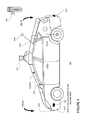
- FIG. 4 is an example diagram of a vehicle in accordance with aspects of the disclosure.
- FIG. 5 is an example of a road in accordance with aspects of the disclosure.
- FIG. 6 is example data in accordance with aspects of the disclosure.
- FIG. 7 is a flow diagram in accordance with aspects of the disclosure.
- FIG. 8 is an example of a road in accordance with aspects of the disclosure.
- FIG. 9 is example data in accordance with aspects of the disclosure.
- FIG. 10 is another flow diagram in accordance with aspects of the disclosure.
- FIG. 11 is a further flow diagram in accordance with aspects of the disclosure.
- an autonomous vehicle system 100 in accordance with one aspect of the disclosure includes a vehicle 101 with various components. While certain aspects of the disclosure are particularly useful in connection with specific types of vehicles, the vehicle 101 may be any type of vehicle including, but not limited to, cars, trucks, motorcycles, busses, boats, airplanes, helicopters, lawnmowers, recreational vehicles, amusement park vehicles, farm equipment, construction equipment, trams, golf carts, trains, and trolleys.
- the vehicle may have one or more computers, such as a computer 110 containing a processor 120 , memory 130 and other components typically present in general purpose computers.
- the processor 120 may be any conventional processor, such as commercially available CPUs. Alternatively, the processor may be a dedicated device such as an ASIC or other hardware-based processor.
- FIG. 1 functionally illustrates the processor, memory, and other elements of computer 110 as being within the same block, it will be understood by those of ordinary skill in the art that the processor, computer, or memory may actually comprise multiple processors, computers, or memories that may or may not be stored within the same physical housing.
- memory may be a hard drive or other storage media located in a housing different from that of computer 110 .
- references to a processor or computer will be understood to include references to a collection of processors or computers or memories that may or may not operate in parallel.
- some of the components such as steering components, acceleration and deceleration components, may each have their own processor that only performs calculations related to the component's specific function.
- the processor 120 may be located remotely from the vehicle 101 and communicate with the vehicle 101 wirelessly. In other aspects, some of the processes described herein are executed on a processor disposed within the vehicle 101 and others by a remote processor, including taking the steps necessary to execute a single maneuver.
- the memory 130 stores information accessible by the processor 120 , including instructions 132 and data 134 that may be executed or otherwise used by the processor 120 .
- the memory 130 may be of any type capable of storing information accessible by the processor, including a computer-readable medium, or other medium that stores data that may be read with the aid of an electronic device, such as a hard-drive, memory card, ROM, RAM, DVD or other optical disks, as well as other write-capable and read-only memories.
- Systems and methods may include different combinations of the foregoing, whereby different portions of the instructions and data are stored on different types of media.
- the instructions 132 may be any set of instructions to be executed directly (such as machine code) or indirectly (such as scripts) by the processor.
- the instructions may be stored as computer code on the computer-readable medium.
- the terms “instructions” and “programs” may be used interchangeably herein.
- the instructions may be stored in object code format for direct processing by the processor, or in any other computer language including scripts or collections of independent source code modules that are interpreted on demand or compiled in advance. Functions, methods, and routines of the instructions are explained in more detail below.
- the data 134 may be retrieved, stored or modified by processor 120 in accordance with the instructions 132 .
- the data may be stored in computer registers, in a relational database as a table having a plurality of different fields and records, XML documents or flat files.
- the data may also be formatted in any computer-readable format.
- image data may be stored as bitmaps comprised of grids of pixels that are stored in accordance with formats that are compressed or uncompressed, lossless (e.g., BMP) or lossy (e.g., JPEG), and bitmap or vector-based (e.g., SVG), as well as computer instructions for drawing graphics.
- the data may comprise any information sufficient to identify the relevant information, such as numbers, descriptive text, proprietary codes, references to data stored in other areas of the same memory or different memories (including other network locations) or information that is used by a function to calculate the relevant data.
- the data may include environmental data that was obtained at a previous point in time and is expected to persist regardless of the vehicle's presence in the environment.
- data 134 may include detailed map information 136 , e.g., highly detailed maps detecting the shape and elevation of roadways, lane lines, intersections, crosswalks, speed limits, traffic signals, buildings, signs, real time traffic information, or other such features and information. These features may be persistent, for example, as described in more detail below, when the vehicle 101 approaches the location of a feature in the detailed map information, the computer 110 may expect to detect the feature.
- the detailed map information may also include explicit speed limit information associated with various roadway segments.
- the speed limit data may be entered manually or scanned from previously taken images of a speed limit sign using, for example, optical-character recognition.
- the detailed map information may also include two-dimensional street-level imagery, such as highly detailed image data depicting the surroundings of a vehicle from the vehicle's point-of-view.
- the detailed map information may also include three-dimensional terrain maps incorporating one or more
- the detailed map information 136 may also include zone information, indicating zones that are unsuitable for driving autonomously. For example, an on-ramp, off-ramp, or other complicated or high traffic areas may be identified as such zones as a driver may feel the need to continuously monitor the vehicle in case the driver must take control. Other zones may be identified as unsuitable for any driving, such as a sidewalk, river, mountain, cliff, desert, etc.
- the detailed map information is depicted herein as an image-based map, the map information need not be entirely image based (for example, raster).
- the detailed map information may include one or more roadgraphs or graph networks of information such as roads, lanes, intersections, and the connections between these features.
- Each feature may be stored as graph data and may be associated with information such as a geographic location and whether or not it is linked to other related features, for example, a stop sign may be linked to a road and an intersection, etc.
- the associated data may include grid-based indices of a roadgraph to allow for efficient lookup of certain roadgraph features.
- FIG. 2 depicts a pictorial representation of detailed map information 136 corresponding to the features of a road 210 , for example, those features which computer 110 may expect to detect while on road 210 .
- Markers 220 and 228 represent boundaries on each of the sides of the road 210 . Each boundary may be a curb, guardrail, highway divider, or other form of barrier.
- the detailed map information 136 may identify each type of boundary differently. In the example of FIG. 2 , for instance, the boundaries represented by markers 220 and 228 are both curbs.
- Markers 222 , 224 , and 226 each represent lane lines painted on the surface of the road 210 .
- Each lane line may be a double solid yellow line, single solid white line, single dashed white line, or other form of lane line.
- the detailed map information 136 may identify each type of lane line differently.
- the lane lines represented by markers 222 and 226 are single dashed white lines, indicating that vehicles may cross these lane lines in order to change lanes.
- the lane line represented by marker 224 is a double solid yellow line, indicating that vehicles may not cross this lane line in order to change lanes.
- the detailed map information 136 may contain additional information regarding characteristics of the stored objects.
- the detailed map information may include information regarding the height of the curbs 220 and 228 (e.g., elevating 4 centimeters above the surface of the road 210 ).
- the detailed map information may include information regarding the width of each of the lane lines 222 - 226 .
- Information regarding the width of lane lines 222 and 226 which are single dashed white lines, may indicate that each line has a width of 8 centimeters.
- Information regarding the width of lane line 224 which is a double solid yellow line, may indicate that this line has a width of 20 centimeters.
- Shaded regions 213 and 215 each represent zones unsuitable for driving.
- the detailed map information 136 may identify each type of zone differently (i.e., detecting a desert differently from a river).
- the off-road regions represented by shaded areas 212 and 214 are a desert.
- Data 134 may also include traffic pattern model information 138 , e.g., a highly detailed model indicating the distribution of typical or expected speeds, trajectories, locations, accelerations/decelerations (changes in speed), or other such characteristics of vehicles or other moving objects on the locations of the detailed map information.
- This data may be generated, for example, by observing how vehicles, pedestrians, bicycles, etc. move at different locations in the detailed map information.
- the traffic pattern model information may indicate information pertinent to the entire road.
- the traffic pattern model information may indicate a range of speeds for vehicles travelling along the road 210 of FIG. 2 , specific to each particular lane or independent of the lanes.
- the traffic pattern model information 138 may indicate a range of trajectories for vehicles travelling in particular lanes.
- the range of trajectories for lane 218 may range from due north (driving straight in lane 218 ) to 10 degrees west of north (changing into lane 216 ).
- the traffic pattern model information 138 may indicate a distribution of trajectories for vehicles travelling in lane 216 ranging from due north (driving straight in lane 216 ) to 10 degrees east of north (changing into lane 218 ).
- Data 134 may also include one or more threshold deviation values 139 .
- the threshold values may be set manually by an administrator based on the traffic pattern model information and the detailed map information in order to promote safe driving of the vehicle by computer. These threshold deviation values may indicate acceptable differences from the traffic pattern model information 138 .
- a threshold deviation value 139 may be set at 20 MPH lower than the slowest speed indicated by the traffic pattern model information 138 . This would mean that if the traffic pattern model information 138 for the road 210 indicates that vehicles on the road 210 travel at speeds ranging between 50 MPH and 70 MPH, a threshold deviation value 139 for road 210 may be set at 30 MPH, 20 MPH lower than the slowest speed (50 MPH).
- a threshold deviation value 139 may be set 10 MPH higher than the fastest speed indicated by the traffic pattern model information 138 . This would mean that given the same range of speeds as in the example above, a threshold deviation value may be set at 80 MPH, 10 MPH higher than the fastest speed (70 MPH).
- one or more threshold deviation values 139 may correspond to characteristics of the features of the detailed map information 136 .
- the threshold deviation values may indicate acceptable differences from the detailed map information.
- a threshold deviation value 139 for the width of lane lines in the detailed map information may be set at 6 inches.
- a first threshold deviation value 139 for the lane line 224 may be set at 12 inches, 6 inches thinner than the lane line 224
- a second threshold deviation value 139 may be set at 26 centimeters, 6 inches wider than the lane line 224 .
- the threshold deviation values 139 may be stored in the data 134 with the traffic pattern model information 138 and/or detailed map information 136 . Alternatively, the threshold deviation values 139 may be stored separately from the traffic pattern model information and the detailed map information 136 .
- computer 110 may be incorporated into vehicle 101 .
- vehicle 101 may also include one or more user interfaces for allowing communication between a driver of the vehicle 101 and the computer 110 .
- the user interfaces may include status indicators, electronic displays, and user input devices built into the interior of the vehicle 101 .
- FIG. 3 depicts a design of the interior of an autonomous vehicle.
- the autonomous vehicle 101 may include all of the features of a non-autonomous vehicle, for example: a steering apparatus, such as steering wheel 310 ; a navigation display apparatus, such as navigation display 315 ; and a gear selector apparatus, such as gear shifter 320 .
- the vehicle may also have various user input devices, such as gear shifter 320 , touch screen 317 , or button inputs 319 , for activating or deactivating one or more autonomous driving modes and for enabling a passenger or driver 390 to provide information, such as a navigation destination, to the computer 110 .
- Vehicle 101 may include one or more additional displays.
- the vehicle may include a display 325 for displaying information regarding the status of the autonomous vehicle or its computer.
- the vehicle may include a status bar 330 , to indicate the current status of vehicle 101 .
- status bar 330 displays “D” and “2 mph” indicating that the vehicle is presently in drive mode and is moving at 2 miles per hour (MPH).
- the vehicle may display text on an electronic display, illuminate portions of vehicle 101 , such as steering wheel 310 , or provide various other types of indications.
- the computer 110 may be capable of communicating with various components of the vehicle 101 .
- the computer 110 may be in communication with the vehicle's central processor 160 and may send and receive information from the various systems of vehicle 101 , for example the braking 180 , acceleration 182 , signaling 184 , and navigation 186 systems in order to control the movement, speed, etc. of vehicle 101 .
- computer 110 may control some or all of these functions of vehicle 101 and thus be fully or merely partially autonomous. It will be understood that although various systems and computer 110 are shown within vehicle 101 , these elements may be external to vehicle 101 or physically separated by large distances.
- the vehicle 101 may also have one or more components for detecting the status of the vehicle.
- the vehicle 101 may include a geographic position component 150 in communication with the computer 110 for determining the geographic location of the device.
- the position component may include a GPS receiver to determine the device's latitude, longitude and/or altitude position. Other location systems such as laser-based localization systems, inertial-aided GPS, or camera-based localization may also be used to identify the location of the vehicle.
- the location of the vehicle may include an absolute geographical location, such as latitude, longitude, and altitude as well as relative location information, such as location relative to other cars immediately around it which can often be determined with less noise than absolute geographical location.
- the location of the vehicle may also indicate whether the vehicle 101 is underground (e.g., detecting that the vehicle 101 is in a tunnel or a cave) or above ground.
- the vehicle 101 may also include an accelerometer, gyroscope or other direction/speed detection device 152 to determine the direction and speed of the vehicle or changes thereto.
- the direction/speed detection device 152 may determine its pitch, yaw or roll (or changes thereto) relative to the direction of gravity or a plane perpendicular thereto.
- the direction/speed detection device 152 may also track increases or decreases in speed and the direction of such changes.
- the device's provision of location and orientation data as set forth herein may be provided automatically to the user, computer 110 , other computers and combinations of the foregoing.
- the vehicle may also be equipped with one or more sensors 144 for detecting objects external to the vehicle such as other vehicles, obstacles in the roadway, traffic signals, signs, trees, etc.
- the sensors 144 may include lasers, sonar, radar, cameras or any other detection devices which record data which may be processed by the computer 110 .
- the sensors 144 may be mounted on the vehicle 101 to collect information regarding the environment of the vehicle 101 .
- the vehicle 101 may include lasers 410 and 411 , mounted on the front and top of the vehicle, respectively.
- laser 410 may have a range of 150 meters, a thirty degree vertical field of view, and a thirty degree horizontal field of view.
- laser 411 may have a range of 50-80 meters, a thirty degree vertical field of view, and a 360 degree horizontal field of view.
- Various other ranges and configurations of one or more lasers may also be used.
- the lasers 410 / 411 may provide the vehicle 101 with range and intensity information which the computer may use to detect the location and distance of various objects that absorb/reflect energy from the lasers 410 / 411 .
- the lasers 410 / 411 may measure the distance between the vehicle 101 and the object surfaces facing the vehicle by spinning on its axis and changing its pitch.
- the vehicle 101 may also include various radar units, such as those used for adaptive cruise control systems.
- the radar units may be located on the front and back of the vehicle 101 as well as on either side of the front bumper.
- vehicle 101 includes radar units 420 - 423 located on the side (only one side being shown), front and rear of the vehicle.
- each of these radar units may have a range of 200 meters for an 18 degree field of view as well as a range of 60 meters for a 56 degree field of view.
- Various other ranges and configurations of one or more radar units may also be used.
- a variety of cameras may also be mounted on the vehicle 101 .
- the cameras may be mounted at predetermined distances so that the parallax from the images of 2 or more cameras may be used to compute the distance to various objects.
- the vehicle 101 may include 2 cameras 430 - 431 mounted under a windshield 340 near the rear view mirror (not shown).
- camera 430 may include a range of 200 meters and a 30 degree horizontal field of view
- camera 431 may include a range of 100 meters and a 60 degree horizontal field of view.
- Various other ranges and configurations of one or more cameras may also be used.
- the vehicle 101 may also include a transmitter and receiver 425 .
- the transmitter/receiver 425 may receive and transmit information wirelessly according to various communications protocols, such as cellular (e.g. 3G, 4G) or WiFi (e.g. 802.11, 8021b, g, n, or other such standards).
- the transmitter/receiver 425 may also allow for inter-vehicle communication.
- the transmitter/receiver may also communicate with roadside sensors, such as a camera or laser stationed on the side of a road.
- the transmitter/receiver 425 may be connected to a server computer 455 (having a processor, memory, and instructions, not shown) via a wireless network 445 .
- the server computer 455 may store information used by the computer 110 when controlling the vehicle 101 . Such information may include maps, information about traffic patterns, road conditions, and so forth.
- the server computer 455 may receive from vehicle 101 (via transmitter/receiver 425 ) map updates, map corrections, traffic pattern updates, traffic pattern corrections, as well as other information.
- the server computer 455 may store the received information in memory and/or transmit the information among other autonomous vehicles on the road.
- the aforementioned sensors 144 may allow the vehicle 101 to evaluate and potentially respond to its environment in order to maximize safety for the driver, other drivers, as well as objects or people in the environment. It will be understood that the vehicle types, number and type of sensors, the sensor locations, the sensor fields of view, and the sensors' sensor fields are merely exemplary. Various other configurations may also be utilized.
- the computer 110 may also use input from sensors typical of non-autonomous vehicles.
- these sensors may include tire pressure sensors, engine temperature sensors, brake heat sensors, brake pad status sensors, tire tread sensors, fuel sensors, oil level and quality sensors, air quality sensors (for detecting temperature, humidity, or particulates in the air), etc.
- sensors 144 may continuously update their output to reflect the environment being sensed at or over a range of time, and continuously or as-demanded provide that updated output to the computer so that the computer can determine whether the vehicle's then-current direction or speed should be modified in response to the sensed environment.
- the computer 110 of autonomous vehicle system 100 may maneuver the vehicle 101 autonomously or semiautonomously.
- the computer 110 may receive information from the sensors 144 and positioning components 150 , 152 . This received information may be used to identify the location of the vehicle 101 .
- the location may be used to identify relevant portions of the detailed map information 136 , traffic pattern model information 138 , etc.
- the vehicle may use the detailed map information 136 to refine its location estimate, for example, by comparing the location of objects detected from the sensor data to the detailed map information.
- the computer 110 may also control the movement, speed, etc. of vehicle 101 . This may include taking actions such as activating a brake for braking 180 , an accelerator for acceleration 182 , or controlling the steering without continued input from a driver.
- the computer 110 maneuvers the vehicle 101 along the road 210 discussed above with regard to the detailed map information of FIG. 2 .
- lanes 512 and 514 of the road 210 are designated for southbound traffic, as indicated by direction arrows 532 and 534 (not necessarily present on the road).
- Lanes 516 and 518 are designated for northbound traffic, as indicated by direction arrows 536 and 538 (also not necessarily present on the road).
- Lane lines 522 , 524 , and 526 indicate the boundaries between lanes 512 - 518 while curbs 520 and 528 establish boundaries for each side of the road 210 .
- FIG. 1 In addition to the features of road 210 described with regard to FIG. 2 above, in this example, FIG.
- vehicle 5 includes several other vehicles driving on road 210 .
- vehicle 542 is driving south in lane 512
- vehicle 544 is driving south in lane 514
- vehicle 546 is driving north mostly in lane 516 (but partially in lane 518 )
- vehicle 548 is driving south (against the flow of traffic) in lane 518 .
- the computer 110 may process the data received from the sensors to detect objects and/or features of the road.
- the sensor data may be continuously received by the computer 110 , such that the computer may detect the presence of an object at different times.
- the vehicle may determine a set of characteristics. As the data is taken at different times, these characteristics may include, for example, the locations, speeds, trajectories, types of object, etc.
- the computer 110 may also compare the characteristics and/or sensor data to the detailed map information 136 to increase the accuracy of these determinations.
- FIG. 6 is a pictorial representation of the objects detected by the computer 110 from the sensor data as compared to the map information from FIG. 2 for roadway 210 .
- FIG. 6 depicts the detected objects 620 - 648 overlaid with detailed map information for the road 210 .
- objects 622 , 624 , and 626 represent the computer's detection of the presence of lane lines 522 , 524 , and 526 (show in FIG. 5 )
- objects 620 and 628 represent the computer's detection of the presence of curbs 520 and 528 (shown in FIG. 5 ).
- the curb 520 may be detected by the sensors.
- the computer may process the sensor data and identify object 620 .
- object 620 is represented by a bounding box approximating the location and shape of curb 520 based on the sensor information. Similar processing may be conducted for each of the objects 522 , 524 , 526 , and 528 . Using a similar analysis, the computer 110 may also identify objects 642 , 644 , 646 , and 648 representing vehicles 542 , 544 , 546 , and 548 (shown only in FIG. 5 ). In this example, the location of objects 620 , 622 , 624 , 626 , and 628 generally line up with the location of objects 220 , 222 , 224 , 226 , and 228 of the map information.
- the computer 110 may also determine that objects 620 , 622 , 624 , 626 , and 628 are stationary, while objects 642 , 644 , 646 , and 648 are moving. In addition to the location of these objects, the computer 110 may also determine other characteristics such as the speed, trajectory, and possible type (vehicle, pedestrian, bicycle, etc.) of these objects from the sensor data. As noted above, the computer 110 may also compare the characteristics and/or sensor data to the detailed map information 134 to increase the accuracy of these determinations. For example, given the size, speed, direction, and location of 642 , 644 , 646 , and 648 , the computer 110 may determine that these objects are likely to be other vehicles.
- the computer may compare the characteristics of the detected objects to traffic pattern model information 138 in order to determine a deviation value.
- One or more characteristics in the traffic pattern model information 138 for the relevant road may be compared to one or more characteristics of a detected object. Based on this comparison, the computer 110 may calculate a deviation value representing the deviation between one or more characteristics of the detected object and one or more characteristics of the traffic pattern model information.
- a characteristic of the traffic pattern model information for a particular section of road may indicate that vehicles (or simply moving objects) on this particular section of road 210 typically drive within a range of speeds. This may be compared to the speed of detected objects which are likely to be vehicles (or simply moving objects) in the road.
- a characteristic of the traffic pattern model information 138 for road 210 may indicate that vehicles (or simply moving objects) typically move between 60 and 70 MPH.
- the computer 110 may determine or calculate a deviation value (here a difference in speeds) between the speed of each of the objects likely to be vehicles (here, 642 , 644 , 646 , and 648 ) and the range of speeds in the traffic pattern model information (50-70 MPH).
- computer 110 may determine that objects 646 and 648 are driving at approximately 15 and 20 MPH, respectively.
- the deviation values for each of objects 646 and 648 may be 35 and 30 MPH, respectively, or ⁇ 35 and ⁇ 30 MPH.
- a characteristic of the traffic pattern model information for a particular section of road may indicate how vehicles typically drive on the road, for example, between curbs or between lane lines heading in the direction of the lanes. In other words, a vehicle in a northbound lane should be driving north. This may be compared to the location and trajectory of the detected objects which are likely to be vehicles or simply moving objects in the road.
- a characteristic of the traffic pattern model information 138 may indicate traffic pattern model information that vehicles typically drive between lane lines in lanes.
- vehicles located in the rightmost lane 218 of the road 210 typically drive with a trajectory in a range between due north (i.e., when driving straight in lane 216 ) and 10 degrees west of due north (i.e., when shifting from lane 218 to lane 216 ).
- the locations and trajectories of each of the objects likely to be vehicles may be compared to the typical locations and trajectories of vehicles moving on road 210 .
- computer 110 may determine that object 646 is not fully between lane lines 224 and 226 or 226 and 228 , with a trajectory of north.
- the deviation value for the location of each of objects 646 may be approximately 1 meter or 2 meters as object 646 may be approximately 1 meter from the center of lane 216 or 2 meters from the center of lane 218 .
- object 648 is within lane lines 226 and 228 , and moving with a trajectory of south.
- the range of trajectories may be from 10 degrees west of north to 10 degrees east of north, and the deviation value may be 170 degrees.
- the deviation values may be compared to the threshold deviation values 139 for the relevant characteristic or characteristics.
- the computer 110 may determine whether a particular deviation value is within some relevant threshold deviation value or values from the typical range of characteristics for similar objects on the same road.
- threshold deviation values for trajectories may be compared to deviation values for trajectories
- threshold deviation values for locations may be compared to deviation values for locations, and so on.
- the computer 110 not only compares the detected objects and characteristics to the traffic pattern model information 138 , but also determines whether these characteristics fall within an acceptable deviation from the typical values. This may allow computer 110 to determine the actual traffic conditions proximate to vehicle 101 in real time.
- objects 646 and 648 may be moving at approximately 15 and 20 MPH.
- the computer 110 may compare the determined deviation values, 35 and 30 MPH or ⁇ 35 and ⁇ 30 MPH, respectively, to the threshold deviation values for speed of vehicles on road 210 . If the threshold deviation value is ⁇ 32 MPH, then the deviation value of object 646 is less than the threshold deviation value while the deviation value of object 648 is greater than the threshold deviation value. This may indicate that object 646 is not within the acceptable range of speeds for road 210 , while object 648 is within the acceptable range of speeds for road 210 .
- both vehicles may be driving relatively slowly as compared to the typical speeds for vehicles on road 210 . This may be indicative of heavy traffic, congestion, temporary roadwork, a broken down vehicle, etc.
- multiple characteristics of an object may be compared. For example, returning to the example of FIG. 6 , object 646 is not between lane lines 224 and 226 or between lane lines 226 or 228 , with a trajectory of north.
- the deviation value for object 646 may be approximately 1 meter or 2 meters as object 646 may be approximately 1 meter from the center of lane 216 or 2 meters from the center of lane 218 . Because the trajectory of vehicle 646 is north, the deviation value for the location of a vehicle within lane lines 224 and 226 or 226 and 228 may be only a few, for example 1-2, feet. Thus, object 646 may be outside of the acceptable ranges. If the trajectory of the vehicle 646 is at least 15 degrees from north, this may indicate that vehicle 646 is changing lanes and thus the acceptable deviation value for location may be higher (for example the width of an entire lane).
- object 648 is within lane lines 226 and 228 , and moving with a trajectory of south.
- the deviation value may be 170 degrees and the threshold deviation value for vehicles traveling between lane lines 226 and 228 may be 40 degrees from 10 degrees west of north or 10 degrees east of north.
- object 648 may be outside of the acceptable range.
- the computer may process characteristics of multiple objects. For example, returning to the example of objects 646 and 648 moving relatively slowly, the computer 110 may look at the characteristics for both vehicles and compare them to threshold deviation values for multiple objects. In this example, the relatively slow speeds of both vehicles may indicate a traffic jam.
- the above examples are examples of situations in which the computer 110 may determine that a deviation value is outside of the relevant threshold deviation value.
- the computer 110 may determine that a deviation value is outside of a threshold deviation value 139 in other situations, such as those in which a driver of the vehicle 101 would feel uncomfortable or feel the need to take control of the vehicle 101 .
- the computer 110 may continue to maneuver the vehicle autonomously or semiautonomously. Alternatively, if the computer 110 determines that the deviation value exceeds the relevant threshold deviation value, the computer 110 may generate and provide an alert to the driver.
- the alert may request the driver take control of the vehicle 101 .
- the alert may be an aural signal, a visual signal, and/or any other signal that gets the attention of the driver.
- the autonomous vehicle system 100 After alerting the driver, the autonomous vehicle system 100 then receives input from the driver. For example, the driver may take control of the vehicle 101 by turning the steering wheel, applying the brake, applying the accelerator, pressing an emergency shut-off, etc. If the computer 110 does not receive input (or sufficient input) from the driver, the computer 110 may navigate the vehicle 101 to the side of the road (i.e., pull the vehicle over), reduce the speed of the vehicle 101 , or bring the vehicle 101 to a complete stop.
- the driver may take control of the vehicle 101 by turning the steering wheel, applying the brake, applying the accelerator, pressing an emergency shut-off, etc.
- the computer 110 may navigate the vehicle 101 to the side of the road (i.e., pull the vehicle over), reduce the speed of the vehicle 101 , or bring the vehicle 101 to a complete stop.
- the computer 110 may take some other action.
- computer 110 may take a defensive action, such as slowing down vehicle 101 or giving a larger distance between vehicle 101 and other objects. This may be especially useful under conditions such as very slow traffic where disengaging the autonomous mode may not actually be necessary.
- the computer may also maneuver the vehicle in order to change lanes to avoid whatever the problem may be.
- the computer may also log the sensor data and traffic information for later examination. For example, this information may be transmitted to a reporting server, such as server 455 , for quality control review. Server 455 may also send the information to other autonomous or non-autonomous vehicles. Alternatively, the computer 110 may transmit this information directly to other vehicles. This may allow for a vehicle's computer to directly identify traffic conditions, react to them, and share them with other vehicles without requiring action from the driver.
- server 455 may also send the information to other autonomous or non-autonomous vehicles.
- the computer 110 may transmit this information directly to other vehicles. This may allow for a vehicle's computer to directly identify traffic conditions, react to them, and share them with other vehicles without requiring action from the driver.
- FIG. 7 illustrates an example flow chart 700 in accordance with some of the aspects described above.
- the computer 110 maneuvers the vehicle.
- the computer 110 receives data from one or more sensors at block 704 .
- the computer 110 may receive information from a laser, camera, radar unit, etc.
- the computer processes the sensor data to detect one or more objects and one or more characteristics of those one or more objects at block 706 .
- the computer 110 compares the one or more characteristics of the detected object to traffic pattern model information at block 708 . For example, a characteristic for speed of an object may be compared to a typical speed of objects from the model.
- the computer 110 determines a deviation value for the compared characteristics at block 710 .
- the computer determines whether the deviation values are within threshold values for the relevant characteristics at block 712 . If so, the computer 110 continues to maneuver the vehicle at block 702 , for example, based on the received sensor data. Returning to block 714 , if the deviation values are not within the relevant threshold deviation values at block 712 , the computer 110 generates an alert to the driver at block 714 . For example, as described above, the computer 110 may cause a message to be displayed or played to the driver to inform him or her of the need to take control of the vehicle.
- the computer 110 may compare the characteristics of the detected objects to detailed map information 136 in order to determine whether there is a mismatch between the collected sensor data and the detailed map information 136 . This may be especially useful when the characteristics of the road have changed and have not yet been updated in the detailed map information.
- FIG. 8 depicts a road 810 corresponding to the same location as road 210 .
- the lanes of the road 210 may be repositioned, for example, by repainting the lane lines of road 210 to change the characteristics of the road.
- road 810 may include four lanes, 812 , 814 , 816 , and 818 .
- Each of these lanes may be associated with a respective traffic directions, direction arrows 832 , 834 , 836 in the south bound direction and direction arrow 838 in the north bound direction.
- these features, 832 , 834 , 836 and 838 are not necessarily present on the road 810 .
- the positions for the lane line 222 and boundaries 220 and 228 on the road 210 are identical to the positions of the lane line 822 and the boundaries 820 and 828 on road 810 (shown in FIG. 8 ).
- double lane lines 826 have been added to the surface of road 810 one meter to the right of the previous location of lane line 226
- a single lane line 824 has been added to the surface of the new road 810 a half meter to the right of the previous location of lane line 224 .
- the computer 110 may detect objects from the sensor data and the locations of the detected objects. The computer 110 may then compare the detected objects and associated locations to the detailed map information. As described above with regard to FIG. 2 , the detailed map information 136 for a particular section of road, such as road 210 , may indicate the positions of stationary objects such as lane lines for the particular section of road which the computer 110 may expect to observe or detect from the sensor data.
- FIG. 9 is a pictorial representation of the objects detected by the computer 110 from the sensor data while driving along road 810 or what the computer 110 identifies as road 210 based on the vehicle's location.
- detected objects 920 , 922 , 924 , 926 , and 928 are overlaid with detailed map information for the road 210 .
- the data for the detected objects 920 , 922 , 924 , 926 , and 928 may reflect the changes made to road 210
- the detailed map information 136 may not reflect these changes if the detailed map information 136 has not been updated since the road 210 was changed.
- the computer 110 may calculate a deviation value representing the difference from or deviation in position of the detected objects and features of the detailed map information 136 .
- the computer 110 may calculate a deviation value (here a difference in positions) between the position of each of the detected objects 920 - 928 and the positions of the objects 220 - 228 in the detailed map information 136 .
- a separate deviation value may be calculated between the object and each of the objects 220 - 228 or between the position of the detected objects 924 and 926 relative to features with similar shape, location, and/or size characteristics.
- object 924 may be compared to the closest feature of road 210 , or double lane lines 224 .
- the characteristics of object 924 may be compared with the characteristics of double lane lines 224 . If the object 924 is 2 feet from double lines 224 , the deviation value for the location of object 924 may be 2 feet. Similarly, object 926 may be compared to the closest feature of road 210 , or lane line 226 . In this case, the deviation value for the object 926 may be 3 feet from lane line 226 .
- the computer 110 may calculate a deviation value (here a difference in shape) between the shape of each of the detected objects 920 - 928 and the shapes of the objects 220 - 228 in the detailed map information 136 .
- a deviation value here a difference in shape
- a separate deviation value may be calculated between the characteristics of each detected object and each of the features of the map information with similar shape, location, and/or size characteristics.
- detected object 924 may actually be a lane line with a detected width of approximately 6 inches
- object 926 may actually be a double lane line with a detected width of 18 inches.
- the deviation values for the detected object 924 may be zero (or negligibly small) when compared to the shape of objects 222 and 226 (also having a width of 6 inches), and 12 inches when compared to the shape of object 224 (having a width of 18 inches, 12 inches greater than the detected width of object 924 ).
- the deviation values for the detected object 926 may be zero when compared to the shape of object 224 , but may be 12 inches when compared to the shape of objects 222 and 226 .
- the deviation values may be compared to the threshold deviation values 139 for the relevant characteristics of the feature or features of the detailed map information.
- the computer 110 may determine whether a particular deviation value 139 is within an acceptable threshold deviation value or values from the features of the detailed map information.
- the threshold deviation value for the location of lane lines may be a few inches or a foot whereas the threshold deviation value for double lane lines may be more or less.
- both of these objects are not within the threshold deviation values for double lane line 224 or lane lines 226 .
- these detected objects may not be within the acceptable range of locations for the double lane lines 224 and lane lines 226 .
- the threshold deviation value for one characteristic of the object may be affected by a deviation value for a second characteristic of the object.
- detected object 924 may be within the acceptable range of locations to be detected as lane line 224 if the threshold deviation value 139 for the location of an object is 2 feet. However, detected object 924 may not have the same size and shape characteristics as lane line 224 . In this example, if the threshold deviation value 139 for the shape of lane lines (such as lane line 226 or double lane line 224 ) is 6 inches, then the deviation value for the shape of detected object 924 , compared to double lane line 224 , may be greater than or not within of the threshold deviation value 139 .
- the computer may process characteristics of multiple objects. For example, returning to the example of objects 924 and 926 , the computer 110 may look at the characteristics for both lane lines and compare them to threshold deviation values for multiple objects. In this example, the mismatch between the positions and shapes of these lane lines and the positions and shapes of the objects in the detailed map information may indicate a significant change in road 210 .
- the above examples are examples of situations in which the computer 110 may determine that a deviation value is outside of the relevant threshold deviation value. In other words, there is a mismatch between the map information and the actual world.
- the computer 110 may determine that a deviation value is outside of a threshold deviation value in other situations, such as those in which the computer 110 cannot detect objects on a road that correspond with objects featured in the detailed map information 136 .
- the computer 110 may continue to maneuver the vehicle 101 autonomously or semiautonomously. Alternatively, if the computer 110 determines that the deviation value exceeds the relevant threshold deviation value 139 , the computer 110 may generate and provide an alert to the driver.
- the alert may request the driver take control of the vehicle 101 .
- the alert may be an aural signal, a visual signal, and/or any other signal that gets the attention of the driver.
- the computer 110 may then receive input from the driver. For example, the driver may take control of the vehicle 101 by turning the steering wheel 310 , applying the brake, applying the accelerator, pressing an emergency shut-off, etc. If the computer 110 does not receive input (or sufficient input) from the driver, the computer 110 may navigate the vehicle 101 to the side of the road (i.e., pull the vehicle over), reduce the speed of the vehicle 101 , or bring the vehicle 101 to a complete stop.
- the computer 110 may take some other action such as slow down vehicle 101 or avoid the mismatched area by driving around it (if possible).
- the computer may also log the sensor data and mismatch information for later examination. For example, this information may be transmitted to a reporting server, such as server 455 , for quality control review. Server 455 may also send the information to other autonomous or non-autonomous vehicles.
- the computer 110 may transmit this information directly to other vehicles. This may allow for a vehicle's computer to directly identify mismatch conditions, react to them, and share them with other vehicles without requiring action from the driver.
- FIG. 10 illustrates an example flow chart 1000 in accordance with some of the aspects described above.
- the computer 110 maneuvers the vehicle as described above.
- the computer 110 receives data from one or more sensors at block 1004 .
- the computer 110 may receive information from a laser, camera, radar unit, etc.
- the computer processes the sensor data to detect one or more objects and one or more characteristics of those one or more objects at block 1006 .
- the computer 110 compares the one or more characteristics of the detected object to detailed map information at block 1008 . For example, a characteristic for the location or size of a stationary object may be compared to the locations of objects in the detailed map information 136 .
- the computer 110 determines a deviation value for the compared one or more characteristics at block 1010 .
- the computer determines whether the deviation values are within threshold values for the relevant characteristics at block 1012 . If so, the computer 110 continues to maneuver the vehicle at block 1002 , for example, based on the received sensor data.
- the computer 110 generates an alert to the driver at block 1014 . For example, as described above, the computer 110 may cause a message to be displayed or played to the driver to inform him or her of the need to take control of the vehicle.
- FIG. 11 is a flow diagram 1100 illustrating one of many possible combinations of the aspects described above.
- the computer 110 maneuvers the vehicle as described above.
- the computer 110 receives data from one or more sensors at block 1104 .
- the computer 110 may receive information from a laser, camera, radar unit, etc.
- the computer processes the sensor data to detect one or more objects and one or more characteristics of those one or more objects at block 1106 .
- the computer 110 compares the one or more characteristics of the detected object to detailed map information at block 1108 .
- the location, size, and/or shape of an object may be compared to the locations of objects in the detailed map information 136 .
- the computer 110 determines a deviation value for the compared one or more characteristics at block 1110 .
- the computer determines whether the deviation values are within threshold values for the relevant characteristics at block 1112 . If the deviation values are not within the relevant threshold deviation values at block 1112 , the computer 110 generates an alert to the driver at block 1120 .
- the computer 110 may cause a message to be displayed or played to the driver to inform him or her of the need to take control of the vehicle.
- the computer 110 compares the one or more characteristics of the detected object to traffic pattern model information at block 1114 . For example, a characteristic for speed of an object may be compared to a typical speed of objects from the model. The computer 110 then determines a deviation value for the compared characteristics at block 1116 . The computer then determines whether the deviation values are within threshold values for the relevant characteristics at block 1118 . If so, the computer 110 continues to maneuver the vehicle at block 1102 , for example, based on the received sensor data.
- the computer 110 generates an alert to the driver at block 1120 . For example, as described above, the computer 110 may cause a message to be displayed or played to the driver to inform him or her of the need to take control of the vehicle.
- the computer 110 may rely on other information to determine whether to alert a driver to take control of the vehicle.
- the computer 110 may use various sensors such as atmospheric sensors or moisture sensors to detect current weather conditions. This sensor data may be supplemented by information received at the vehicle, for example, weather reports. If the weather conditions indicate an unsafe situation for the vehicle, for example, icy conditions or heavy snow, the computer 110 may generate and provide an alert to the driver as described above.
Abstract
Description
Claims (39)
Priority Applications (2)
| Application Number | Priority Date | Filing Date | Title |
|---|---|---|---|
| US13/444,215 US8718861B1 (en) | 2012-04-11 | 2012-04-11 | Determining when to drive autonomously |
| US14/220,653 US8954217B1 (en) | 2012-04-11 | 2014-03-20 | Determining when to drive autonomously |
Applications Claiming Priority (1)
| Application Number | Priority Date | Filing Date | Title |
|---|---|---|---|
| US13/444,215 US8718861B1 (en) | 2012-04-11 | 2012-04-11 | Determining when to drive autonomously |
Related Child Applications (1)
| Application Number | Title | Priority Date | Filing Date |
|---|---|---|---|
| US14/220,653 Continuation US8954217B1 (en) | 2012-04-11 | 2014-03-20 | Determining when to drive autonomously |
Publications (1)
| Publication Number | Publication Date |
|---|---|
| US8718861B1 true US8718861B1 (en) | 2014-05-06 |
Family
ID=50552891
Family Applications (2)
| Application Number | Title | Priority Date | Filing Date |
|---|---|---|---|
| US13/444,215 Active 2032-07-31 US8718861B1 (en) | 2012-04-11 | 2012-04-11 | Determining when to drive autonomously |
| US14/220,653 Active US8954217B1 (en) | 2012-04-11 | 2014-03-20 | Determining when to drive autonomously |
Family Applications After (1)
| Application Number | Title | Priority Date | Filing Date |
|---|---|---|---|
| US14/220,653 Active US8954217B1 (en) | 2012-04-11 | 2014-03-20 | Determining when to drive autonomously |
Country Status (1)
| Country | Link |
|---|---|
| US (2) | US8718861B1 (en) |
Cited By (128)
| Publication number | Priority date | Publication date | Assignee | Title |
|---|---|---|---|---|
| US20140371972A1 (en) * | 2011-09-01 | 2014-12-18 | Valeo Schalter Und Sensoren Gmbh | Method for carrying out a parking process for a vehicle and driver assistance device |
| US8948955B2 (en) | 2010-10-05 | 2015-02-03 | Google Inc. | System and method for predicting behaviors of detected objects |
| US8949016B1 (en) | 2012-09-28 | 2015-02-03 | Google Inc. | Systems and methods for determining whether a driving environment has changed |
| US20150110344A1 (en) * | 2013-10-23 | 2015-04-23 | Toyota Motor Engineering & Manufacturing North America, Inc. | Image and map-based detection of vehicles at intersections |
| US20150175070A1 (en) * | 2013-12-20 | 2015-06-25 | Ford Global Technologies, Llc | Affective user interface in an autonomous vehicle |
| US20150178998A1 (en) * | 2013-12-20 | 2015-06-25 | Ford Global Technologies, Llc | Fault handling in an autonomous vehicle |
| US20150191084A1 (en) * | 2012-07-11 | 2015-07-09 | Robert Bosch Gmbh | Method for operating a driver assistance system for a vehicle and driver assistance system for a vehicle |
| US20150253778A1 (en) * | 2014-03-04 | 2015-09-10 | Volvo Car Corporation | Apparatus and method for prediction of time available for autonomous driving, in a vehicle having autonomous driving capabilities |
| US9157752B1 (en) * | 2014-08-08 | 2015-10-13 | Continental Automotive Systems, Inc. | System and method for theft and medical emergency event for self-driving vehicle |
| WO2015179760A1 (en) * | 2014-05-23 | 2015-11-26 | Google Inc. | Autonomous vehicles |
| US9248834B1 (en) | 2014-10-02 | 2016-02-02 | Google Inc. | Predicting trajectories of objects based on contextual information |
| EP3007055A1 (en) * | 2014-10-10 | 2016-04-13 | Volvo Car Corporation | A dual operational touch screen device for a vehicle |
| US9321461B1 (en) * | 2014-08-29 | 2016-04-26 | Google Inc. | Change detection using curve alignment |
| WO2016066416A1 (en) * | 2014-10-27 | 2016-05-06 | Robert Bosch Gmbh | Method and apparatus for determining a current driving situation |
| DE102015118489A1 (en) | 2014-11-13 | 2016-05-19 | Toyota Motor Engineering & Manufacturing North America, Inc. | Remote control of an autonomous vehicle in an unexpected environment |
| US9347779B1 (en) * | 2014-12-10 | 2016-05-24 | Here Global B.V. | Method and apparatus for determining a position of a vehicle based on driving behavior |
| US9365213B2 (en) * | 2014-04-30 | 2016-06-14 | Here Global B.V. | Mode transition for an autonomous vehicle |
| US20160288791A1 (en) * | 2013-04-01 | 2016-10-06 | Young-II PARK | Automatic driving system for vehicle |
| WO2016200762A1 (en) * | 2015-06-08 | 2016-12-15 | Allstate Insurance Company | Route risk mitigation |
| GB2539548A (en) * | 2015-04-23 | 2016-12-21 | Ford Global Tech Llc | Traffic complexity estimation |
| US9528834B2 (en) | 2013-11-01 | 2016-12-27 | Intelligent Technologies International, Inc. | Mapping techniques using probe vehicles |
| GB2539772A (en) * | 2015-05-05 | 2016-12-28 | Ford Global Tech Llc | Hands-off steering wheel governed by pedestrian detection |
| US9547307B1 (en) | 2014-05-23 | 2017-01-17 | Google Inc. | Attempting to pull over for autonomous vehicles |
| US20170038774A1 (en) * | 2014-04-25 | 2017-02-09 | Nissan Motor Co., Ltd. | Information Presenting Apparatus and Information Presenting Method |
| CN106407806A (en) * | 2015-07-30 | 2017-02-15 | 丰田自动车株式会社 | System and method for detecting attack |
| US9573600B2 (en) | 2014-12-19 | 2017-02-21 | Toyota Motor Engineering & Manufacturing North America, Inc. | Method and apparatus for generating and using driver specific vehicle controls |
| US20170059335A1 (en) * | 2015-09-02 | 2017-03-02 | Ford Global Technologies, Llc | Autonomous Driving Certification Generalizer |
| WO2017040936A1 (en) * | 2015-09-04 | 2017-03-09 | Inrix, Inc. | Manual vehicle control notification |
| US9594373B2 (en) | 2014-03-04 | 2017-03-14 | Volvo Car Corporation | Apparatus and method for continuously establishing a boundary for autonomous driving availability and an automotive vehicle comprising such an apparatus |
| US9633564B2 (en) | 2012-09-27 | 2017-04-25 | Google Inc. | Determining changes in a driving environment based on vehicle behavior |
| CN106796760A (en) * | 2014-10-13 | 2017-05-31 | 大陆汽车有限公司 | Communication equipment for the vehicles and the method for communicating |
| US20170168484A1 (en) * | 2015-12-14 | 2017-06-15 | Robert Bosch Gmbh | Method for transmitting, receiving and processing data values, and a transmission device and receiving device |
| CN107042828A (en) * | 2016-02-05 | 2017-08-15 | 福特全球技术公司 | Vehicle operating states |
| US9733096B2 (en) | 2015-06-22 | 2017-08-15 | Waymo Llc | Determining pickup and destination locations for autonomous vehicles |
| US20170232974A1 (en) * | 2014-11-07 | 2017-08-17 | Denso Corporation | Drive assistance system and center |
| US20170243491A1 (en) * | 2016-02-19 | 2017-08-24 | Honda Motor Co., Ltd. | Lane change assistance device |
| EP3232289A1 (en) * | 2016-04-15 | 2017-10-18 | Panasonic Intellectual Property Corporation of America | Information presentation control apparatus, autonomous vehicle, and autonomous-vehicle driving support system |
| US20170341575A1 (en) * | 2016-05-27 | 2017-11-30 | Robert Bosch Gmbh | Method and device for automatically stopping a motor vehicle that is at least intermittently automatically guided on a route |
| US9865019B2 (en) | 2007-05-10 | 2018-01-09 | Allstate Insurance Company | Route risk mitigation |
| US20180025235A1 (en) * | 2016-07-21 | 2018-01-25 | Mobileye Vision Technologies Ltd. | Crowdsourcing the collection of road surface information |
| US20180059661A1 (en) * | 2016-08-26 | 2018-03-01 | Toyota Jidosha Kabushiki Kaisha | Control system for and control method of autonomous driving vehicle |
| US9908464B2 (en) * | 2016-04-10 | 2018-03-06 | Toyota Motor Engineering & Manufacturing North America, Inc. | Apprising a driver of confidence in operation of a vehicle |
| US9932033B2 (en) | 2007-05-10 | 2018-04-03 | Allstate Insurance Company | Route risk mitigation |
| US9940676B1 (en) | 2014-02-19 | 2018-04-10 | Allstate Insurance Company | Insurance system for analysis of autonomous driving |
| US9989963B2 (en) | 2016-02-25 | 2018-06-05 | Ford Global Technologies, Llc | Autonomous confidence control |
| WO2018119417A1 (en) * | 2016-12-22 | 2018-06-28 | Nissan North America, Inc. | Autonomous vehicle service system |
| US10026317B2 (en) | 2016-02-25 | 2018-07-17 | Ford Global Technologies, Llc | Autonomous probability control |
| CN108349504A (en) * | 2015-11-04 | 2018-07-31 | 日产自动车株式会社 | Automatic driving vehicle operating device and automatic driving vehicle operating method |
| US10096067B1 (en) | 2014-01-24 | 2018-10-09 | Allstate Insurance Company | Reward system related to a vehicle-to-vehicle communication system |
| US10096038B2 (en) | 2007-05-10 | 2018-10-09 | Allstate Insurance Company | Road segment safety rating system |
| US10101742B2 (en) | 2014-12-07 | 2018-10-16 | Toyota Motor Engineering & Manufacturing North America, Inc. | Mixed autonomous and manual control of autonomous vehicles |
| US20180299888A1 (en) * | 2015-11-24 | 2018-10-18 | Joseph Sullivan | Conflict Resolution via Contingency Plan Execution or Human Interaction |
| US20180312161A1 (en) * | 2015-11-06 | 2018-11-01 | Honda Motor Co., Ltd. | Vehicle travel control device |
| US20180328743A1 (en) * | 2015-11-24 | 2018-11-15 | Joseph Sullivan | Method for Re-mapping Safe and Traversable Routes |
| US10133273B2 (en) * | 2016-09-20 | 2018-11-20 | 2236008 Ontario Inc. | Location specific assistance for autonomous vehicle control system |
| US10157422B2 (en) | 2007-05-10 | 2018-12-18 | Allstate Insurance Company | Road segment safety rating |
| US20190078896A1 (en) * | 2017-09-13 | 2019-03-14 | Baidu Usa Llc | Data driven map updating system for autonomous driving vehicles |
| US20190077415A1 (en) * | 2017-09-08 | 2019-03-14 | Subaru Corporation | Alarm apparatus |
| US10242569B2 (en) | 2016-03-09 | 2019-03-26 | Toyota Jidosha Kabushiki Kaisha | Information providing apparatus for vehicle |
| US10262538B1 (en) * | 2016-09-22 | 2019-04-16 | Apple Inc. | Database management for potential pull-off areas |
| US10269075B2 (en) | 2016-02-02 | 2019-04-23 | Allstate Insurance Company | Subjective route risk mapping and mitigation |
| US10289113B2 (en) | 2016-02-25 | 2019-05-14 | Ford Global Technologies, Llc | Autonomous occupant attention-based control |
| US10351147B2 (en) * | 2016-09-20 | 2019-07-16 | Ford Global Technologies, Llc | Autonomous sensing vehicle pedals |
| US10365647B2 (en) | 2017-03-29 | 2019-07-30 | Qualcomm Incorporated | Ensuring occupant awareness in vehicles |
| US10442439B1 (en) | 2016-08-18 | 2019-10-15 | Apple Inc. | System and method for road friction coefficient estimation |
| US20190317519A1 (en) * | 2018-04-17 | 2019-10-17 | Baidu Usa Llc | Method for transforming 2d bounding boxes of objects into 3d positions for autonomous driving vehicles (advs) |
| US20190377351A1 (en) * | 2018-06-06 | 2019-12-12 | Uber Technologies, Inc. | Gridlock Solver for Motion Planning System of an Autonomous Vehicle |
| US10552979B2 (en) | 2017-09-13 | 2020-02-04 | TuSimple | Output of a neural network method for deep odometry assisted by static scene optical flow |
| US10565728B2 (en) | 2018-06-01 | 2020-02-18 | Tusimple, Inc. | Smoothness constraint for camera pose estimation |
| US10571911B2 (en) * | 2014-12-07 | 2020-02-25 | Toyota Motor Engineering & Manufacturing North America, Inc. | Mixed autonomous and manual control of a vehicle |
| US10627813B2 (en) * | 2015-04-21 | 2020-04-21 | Panasonic Intellectual Property Management Co., Ltd. | Information processing system, information processing method, and program |
| US10664918B1 (en) | 2014-01-24 | 2020-05-26 | Allstate Insurance Company | Insurance system related to a vehicle-to-vehicle communication system |
| US10671083B2 (en) | 2017-09-13 | 2020-06-02 | Tusimple, Inc. | Neural network architecture system for deep odometry assisted by static scene optical flow |
| US10679074B2 (en) | 2017-03-10 | 2020-06-09 | Tusimple, Inc. | System and method for semantic segmentation using hybrid dilated convolution (HDC) |
| US10733673B1 (en) | 2014-01-24 | 2020-08-04 | Allstate Insurance Company | Reward system related to a vehicle-to-vehicle communication system |
| US10753753B2 (en) | 2017-05-26 | 2020-08-25 | Ford Global Technologies, Llc | Vehicle route navigation |
| US10762635B2 (en) | 2017-06-14 | 2020-09-01 | Tusimple, Inc. | System and method for actively selecting and labeling images for semantic segmentation |
| US10762673B2 (en) | 2017-08-23 | 2020-09-01 | Tusimple, Inc. | 3D submap reconstruction system and method for centimeter precision localization using camera-based submap and LiDAR-based global map |
| CN111655559A (en) * | 2018-01-31 | 2020-09-11 | 雷诺股份公司 | System and method for controlling a motor vehicle to negotiate low obstacles |
| US10775783B2 (en) | 2016-08-04 | 2020-09-15 | Kevin Lawler | System for asymmetric just-in-time human intervention in automated vehicle fleets |
| US10783587B1 (en) * | 2014-02-19 | 2020-09-22 | Allstate Insurance Company | Determining a driver score based on the driver's response to autonomous features of a vehicle |
| US10783586B1 (en) | 2014-02-19 | 2020-09-22 | Allstate Insurance Company | Determining a property of an insurance policy based on the density of vehicles |
| US10796369B1 (en) | 2014-02-19 | 2020-10-06 | Allstate Insurance Company | Determining a property of an insurance policy based on the level of autonomy of a vehicle |
| US10803525B1 (en) * | 2014-02-19 | 2020-10-13 | Allstate Insurance Company | Determining a property of an insurance policy based on the autonomous features of a vehicle |
| CN111791888A (en) * | 2019-03-19 | 2020-10-20 | 丰田自动车株式会社 | Driving assistance device |
| US10816354B2 (en) | 2017-08-22 | 2020-10-27 | Tusimple, Inc. | Verification module system and method for motion-based lane detection with multiple sensors |
| US10832426B2 (en) | 2015-09-24 | 2020-11-10 | Apple Inc. | Systems and methods for surface monitoring |
| US10845209B2 (en) * | 2017-12-19 | 2020-11-24 | Uatc, Llc | System and method for presenting autonomy switching directions |
| US10929462B2 (en) * | 2017-02-02 | 2021-02-23 | Futurewei Technologies, Inc. | Object recognition in autonomous vehicles |
| US10942271B2 (en) | 2018-10-30 | 2021-03-09 | Tusimple, Inc. | Determining an angle between a tow vehicle and a trailer |
| US10948924B2 (en) | 2015-02-06 | 2021-03-16 | Aptiv Technologies Limited | Method and apparatus for controlling an autonomous vehicle |
| US10953881B2 (en) | 2017-09-07 | 2021-03-23 | Tusimple, Inc. | System and method for automated lane change control for autonomous vehicles |
| US10953880B2 (en) | 2017-09-07 | 2021-03-23 | Tusimple, Inc. | System and method for automated lane change control for autonomous vehicles |
| US10991247B2 (en) | 2015-02-06 | 2021-04-27 | Aptiv Technologies Limited | Method of automatically controlling an autonomous vehicle based on electronic messages from roadside infrastructure or other vehicles |
| US11009365B2 (en) | 2018-02-14 | 2021-05-18 | Tusimple, Inc. | Lane marking localization |
| US11009356B2 (en) | 2018-02-14 | 2021-05-18 | Tusimple, Inc. | Lane marking localization and fusion |
| US11010874B2 (en) | 2018-04-12 | 2021-05-18 | Tusimple, Inc. | Images for perception modules of autonomous vehicles |
| US11019274B2 (en) | 2018-09-10 | 2021-05-25 | Tusimple, Inc. | Adaptive illumination for a time-of-flight camera on a vehicle |
| US11023742B2 (en) | 2018-09-07 | 2021-06-01 | Tusimple, Inc. | Rear-facing perception system for vehicles |
| US20210181742A1 (en) * | 2019-12-12 | 2021-06-17 | Baidu Usa Llc | Path planning with a preparation distance for a lane-change |
| US11070756B2 (en) | 2018-01-24 | 2021-07-20 | Tusimple, Inc. | Method, device and system for image acquisition control |
| JP2021104805A (en) * | 2015-02-10 | 2021-07-26 | モービルアイ ビジョン テクノロジーズ リミテッド | Vehicle apparatus for controlling motion of vehicle, vehicle, and computer program |
| US20210229686A1 (en) * | 2018-12-13 | 2021-07-29 | Waymo Llc | Automated Performance Checks For Autonomous Vehicles |
| US11100673B2 (en) | 2015-09-24 | 2021-08-24 | Apple Inc. | Systems and methods for localization using surface imaging |
| US11112790B2 (en) | 2018-12-21 | 2021-09-07 | GM Global Technology Operations LLC | Micro-authorization of remote assistance for an autonomous vehicle |
| US11124163B2 (en) * | 2016-01-29 | 2021-09-21 | Nissan Motor Co., Ltd. | Method for controlling travel of vehicle, and device for controlling travel of vehicle |
| US11151393B2 (en) | 2017-08-23 | 2021-10-19 | Tusimple, Inc. | Feature matching and corresponding refinement and 3D submap position refinement system and method for centimeter precision localization using camera-based submap and LiDAR-based global map |
| US11295146B2 (en) | 2018-02-27 | 2022-04-05 | Tusimple, Inc. | System and method for online real-time multi-object tracking |
| US11292480B2 (en) | 2018-09-13 | 2022-04-05 | Tusimple, Inc. | Remote safe driving methods and systems |
| US11294372B2 (en) | 2019-02-15 | 2022-04-05 | International Business Machines Corporation | Driving mode decision support |
| US11292437B2 (en) | 2017-11-16 | 2022-04-05 | Beijing Tusen Weilai Technology Co., Ltd. | System and method for automated cleaning |
| US11305782B2 (en) | 2018-01-11 | 2022-04-19 | Tusimple, Inc. | Monitoring system for autonomous vehicle operation |
| US20220121215A1 (en) * | 2017-09-08 | 2022-04-21 | Toyota Jidosha Kabushiki Kaisha | Target abnormality determination device |
| US11312334B2 (en) | 2018-01-09 | 2022-04-26 | Tusimple, Inc. | Real-time remote control of vehicles with high redundancy |
| US11391820B2 (en) * | 2019-04-26 | 2022-07-19 | Waymo L LC | Mirrors to extend sensor field of view in self-driving vehicles |
| US11402221B2 (en) * | 2014-12-05 | 2022-08-02 | Apple Inc. | Autonomous navigation system |
| DE102021200822A1 (en) | 2021-01-29 | 2022-08-04 | Siemens Mobility GmbH | Method and device for sensor data processing |
| US11500101B2 (en) | 2018-05-02 | 2022-11-15 | Tusimple, Inc. | Curb detection by analysis of reflection images |
| US11498577B2 (en) * | 2018-04-05 | 2022-11-15 | Toyota Jidosha Kabushiki Kaisha | Behavior prediction device |
| US11549815B2 (en) | 2019-06-28 | 2023-01-10 | GM Cruise Holdings LLC. | Map change detection |
| US11624631B2 (en) | 2015-11-24 | 2023-04-11 | Daxbot Inc. | Autonomous robots and methods for determining, mapping, and traversing routes for autonomous robots |
| US20230189683A1 (en) * | 2021-06-01 | 2023-06-22 | Gint Co., Ltd. | Method of automatically combining farm vehicle and work machine and farm vehicle |
| US11701931B2 (en) | 2020-06-18 | 2023-07-18 | Tusimple, Inc. | Angle and orientation measurements for vehicles with multiple drivable sections |
| USRE49649E1 (en) | 2012-04-13 | 2023-09-12 | Waymo Llc | System and method for automatically detecting key behaviors by vehicles |
| US11810322B2 (en) | 2020-04-09 | 2023-11-07 | Tusimple, Inc. | Camera pose estimation techniques |
| US11823460B2 (en) | 2019-06-14 | 2023-11-21 | Tusimple, Inc. | Image fusion for autonomous vehicle operation |
| US11853071B2 (en) | 2017-09-07 | 2023-12-26 | Tusimple, Inc. | Data-driven prediction-based system and method for trajectory planning of autonomous vehicles |
| US11932238B2 (en) | 2020-06-29 | 2024-03-19 | Tusimple, Inc. | Automated parking technology |
Families Citing this family (84)
| Publication number | Priority date | Publication date | Assignee | Title |
|---|---|---|---|---|
| DE102013219887A1 (en) * | 2013-10-01 | 2015-04-02 | Volkswagen Aktiengesellschaft | Method for a driver assistance system of a vehicle |
| US10599155B1 (en) | 2014-05-20 | 2020-03-24 | State Farm Mutual Automobile Insurance Company | Autonomous vehicle operation feature monitoring and evaluation of effectiveness |
| US10373259B1 (en) | 2014-05-20 | 2019-08-06 | State Farm Mutual Automobile Insurance Company | Fully autonomous vehicle insurance pricing |
| US9972054B1 (en) | 2014-05-20 | 2018-05-15 | State Farm Mutual Automobile Insurance Company | Accident fault determination for autonomous vehicles |
| US9852475B1 (en) | 2014-05-20 | 2017-12-26 | State Farm Mutual Automobile Insurance Company | Accident risk model determination using autonomous vehicle operating data |
| US11669090B2 (en) | 2014-05-20 | 2023-06-06 | State Farm Mutual Automobile Insurance Company | Autonomous vehicle operation feature monitoring and evaluation of effectiveness |
| US10102587B1 (en) | 2014-07-21 | 2018-10-16 | State Farm Mutual Automobile Insurance Company | Methods of pre-generating insurance claims |
| KR20160054825A (en) * | 2014-11-07 | 2016-05-17 | 현대모비스 주식회사 | Apparatus and method for judging drivable space |
| US9946531B1 (en) | 2014-11-13 | 2018-04-17 | State Farm Mutual Automobile Insurance Company | Autonomous vehicle software version assessment |
| US9588517B2 (en) * | 2015-07-14 | 2017-03-07 | Delphi Technologies, Inc. | Automated vehicle control take-over alert timing based on infotainment activation |
| US9869560B2 (en) | 2015-07-31 | 2018-01-16 | International Business Machines Corporation | Self-driving vehicle's response to a proximate emergency vehicle |
| US9483948B1 (en) | 2015-08-07 | 2016-11-01 | International Business Machines Corporation | Automated control of interactions between self-driving vehicles and pedestrians |
| US9785145B2 (en) | 2015-08-07 | 2017-10-10 | International Business Machines Corporation | Controlling driving modes of self-driving vehicles |
| US9721397B2 (en) | 2015-08-11 | 2017-08-01 | International Business Machines Corporation | Automatic toll booth interaction with self-driving vehicles |
| US9718471B2 (en) | 2015-08-18 | 2017-08-01 | International Business Machines Corporation | Automated spatial separation of self-driving vehicles from manually operated vehicles |
| US9481366B1 (en) | 2015-08-19 | 2016-11-01 | International Business Machines Corporation | Automated control of interactions between self-driving vehicles and animals |
| US9896100B2 (en) | 2015-08-24 | 2018-02-20 | International Business Machines Corporation | Automated spatial separation of self-driving vehicles from other vehicles based on occupant preferences |
| US20210272207A1 (en) | 2015-08-28 | 2021-09-02 | State Farm Mutual Automobile Insurance Company | Vehicular driver profiles and discounts |
| US9731726B2 (en) | 2015-09-02 | 2017-08-15 | International Business Machines Corporation | Redirecting self-driving vehicles to a product provider based on physiological states of occupants of the self-driving vehicles |
| US9587952B1 (en) | 2015-09-09 | 2017-03-07 | Allstate Insurance Company | Altering autonomous or semi-autonomous vehicle operation based on route traversal values |
| US9513632B1 (en) | 2015-09-16 | 2016-12-06 | International Business Machines Corporation | Driving mode alerts from self-driving vehicles |
| US9566986B1 (en) | 2015-09-25 | 2017-02-14 | International Business Machines Corporation | Controlling driving modes of self-driving vehicles |
| US9481367B1 (en) | 2015-10-14 | 2016-11-01 | International Business Machines Corporation | Automated control of interactions between self-driving vehicles and animals |
| US9834224B2 (en) | 2015-10-15 | 2017-12-05 | International Business Machines Corporation | Controlling driving modes of self-driving vehicles |
| US10982961B2 (en) * | 2015-10-16 | 2021-04-20 | Hitachi Automotive Systems, Ltd. | Vehicle control system and vehicle control device |
| US9751532B2 (en) | 2015-10-27 | 2017-09-05 | International Business Machines Corporation | Controlling spacing of self-driving vehicles based on social network relationships |
| US9944291B2 (en) | 2015-10-27 | 2018-04-17 | International Business Machines Corporation | Controlling driving modes of self-driving vehicles |
| US10607293B2 (en) | 2015-10-30 | 2020-03-31 | International Business Machines Corporation | Automated insurance toggling for self-driving vehicles |
| US10176525B2 (en) | 2015-11-09 | 2019-01-08 | International Business Machines Corporation | Dynamically adjusting insurance policy parameters for a self-driving vehicle |
| US9791861B2 (en) | 2015-11-12 | 2017-10-17 | International Business Machines Corporation | Autonomously servicing self-driving vehicles |
| US10061326B2 (en) | 2015-12-09 | 2018-08-28 | International Business Machines Corporation | Mishap amelioration based on second-order sensing by a self-driving vehicle |
| US9599986B1 (en) | 2015-12-22 | 2017-03-21 | International Business Machines Corporation | Emergency automated vehicle control system to monitor emergency medical events through body area networks |
| US10324463B1 (en) | 2016-01-22 | 2019-06-18 | State Farm Mutual Automobile Insurance Company | Autonomous vehicle operation adjustment based upon route |
| US10503168B1 (en) | 2016-01-22 | 2019-12-10 | State Farm Mutual Automotive Insurance Company | Autonomous vehicle retrieval |
| US10395332B1 (en) | 2016-01-22 | 2019-08-27 | State Farm Mutual Automobile Insurance Company | Coordinated autonomous vehicle automatic area scanning |
| US11719545B2 (en) | 2016-01-22 | 2023-08-08 | Hyundai Motor Company | Autonomous vehicle component damage and salvage assessment |
| US11242051B1 (en) | 2016-01-22 | 2022-02-08 | State Farm Mutual Automobile Insurance Company | Autonomous vehicle action communications |
| US10134278B1 (en) | 2016-01-22 | 2018-11-20 | State Farm Mutual Automobile Insurance Company | Autonomous vehicle application |
| US11441916B1 (en) | 2016-01-22 | 2022-09-13 | State Farm Mutual Automobile Insurance Company | Autonomous vehicle trip routing |
| US9836973B2 (en) | 2016-01-27 | 2017-12-05 | International Business Machines Corporation | Selectively controlling a self-driving vehicle's access to a roadway |
| US10134280B1 (en) | 2016-02-23 | 2018-11-20 | Taehyun You | Vehicular notifications |
| US20170248953A1 (en) * | 2016-02-25 | 2017-08-31 | Ford Global Technologies, Llc | Autonomous peril control |
| US10255648B2 (en) | 2016-04-14 | 2019-04-09 | Eric John Wengreen | Self-driving vehicle systems and methods |
| US9429947B1 (en) | 2016-04-14 | 2016-08-30 | Eric John Wengreen | Self-driving vehicle systems and methods |
| US10685391B2 (en) | 2016-05-24 | 2020-06-16 | International Business Machines Corporation | Directing movement of a self-driving vehicle based on sales activity |
| CN106056936B (en) * | 2016-06-17 | 2019-01-01 | 京东方科技集团股份有限公司 | A kind of method of adjustment of traveling lane, apparatus and system |
| JP6778872B2 (en) * | 2016-06-28 | 2020-11-04 | パナソニックIpマネジメント株式会社 | Driving support device and driving support method |
| US10093322B2 (en) | 2016-09-15 | 2018-10-09 | International Business Machines Corporation | Automatically providing explanations for actions taken by a self-driving vehicle |
| US10643256B2 (en) | 2016-09-16 | 2020-05-05 | International Business Machines Corporation | Configuring a self-driving vehicle for charitable donations pickup and delivery |
| US10259452B2 (en) | 2017-01-04 | 2019-04-16 | International Business Machines Corporation | Self-driving vehicle collision management system |
| US10529147B2 (en) | 2017-01-05 | 2020-01-07 | International Business Machines Corporation | Self-driving vehicle road safety flare deploying system |
| US10363893B2 (en) | 2017-01-05 | 2019-07-30 | International Business Machines Corporation | Self-driving vehicle contextual lock control system |
| US11187539B2 (en) * | 2017-01-17 | 2021-11-30 | Hitachi, Ltd. | Travel control device for moving body |
| US10152060B2 (en) | 2017-03-08 | 2018-12-11 | International Business Machines Corporation | Protecting contents of a smart vault being transported by a self-driving vehicle |
| US10907974B2 (en) | 2017-04-17 | 2021-02-02 | Cisco Technology, Inc. | Real-time updates to maps for autonomous navigation |
| US10732627B1 (en) | 2017-05-25 | 2020-08-04 | State Farm Mutual Automobile Insurance Company | Driver re-engagement system |
| JP6637932B2 (en) * | 2017-08-03 | 2020-01-29 | 株式会社Subaru | Driving support device for vehicles |
| CN111448597B (en) * | 2017-10-10 | 2022-06-10 | 日产自动车株式会社 | Driving control method and driving control device |
| US11061399B2 (en) | 2018-01-03 | 2021-07-13 | Samsung Electronics Co., Ltd. | System and method for providing information indicative of autonomous availability |
| US11073838B2 (en) | 2018-01-06 | 2021-07-27 | Drivent Llc | Self-driving vehicle systems and methods |
| US10303181B1 (en) | 2018-11-29 | 2019-05-28 | Eric John Wengreen | Self-driving vehicle systems and methods |
| US10299216B1 (en) | 2018-01-06 | 2019-05-21 | Eric John Wengreen | Self-driving vehicle actions in response to a low battery |
| US10274950B1 (en) | 2018-01-06 | 2019-04-30 | Drivent Technologies Inc. | Self-driving vehicle systems and methods |
| US10890909B2 (en) | 2018-01-09 | 2021-01-12 | International Business Machines Corporation | Automobile driving mode determination |
| US10466057B1 (en) | 2018-07-30 | 2019-11-05 | Wesley Edward Schwie | Self-driving vehicle systems and methods |
| US10223844B1 (en) | 2018-09-18 | 2019-03-05 | Wesley Edward Schwie | Self-driving vehicle systems and methods |
| US10479319B1 (en) | 2019-03-21 | 2019-11-19 | Drivent Llc | Self-driving vehicle systems and methods |
| US10289922B1 (en) | 2018-09-18 | 2019-05-14 | Eric John Wengreen | System for managing lost, mislaid, or abandoned property in a self-driving vehicle |
| US10471804B1 (en) | 2018-09-18 | 2019-11-12 | Drivent Llc | Self-driving vehicle systems and methods |
| US10282625B1 (en) | 2018-10-01 | 2019-05-07 | Eric John Wengreen | Self-driving vehicle systems and methods |
| US10493952B1 (en) | 2019-03-21 | 2019-12-03 | Drivent Llc | Self-driving vehicle systems and methods |
| US10900792B2 (en) | 2018-10-22 | 2021-01-26 | Drivent Llc | Self-driving vehicle systems and methods |
| US10832569B2 (en) | 2019-04-02 | 2020-11-10 | Drivent Llc | Vehicle detection systems |
| US11221622B2 (en) | 2019-03-21 | 2022-01-11 | Drivent Llc | Self-driving vehicle systems and methods |
| US11644833B2 (en) | 2018-10-01 | 2023-05-09 | Drivent Llc | Self-driving vehicle systems and methods |
| US10794714B2 (en) | 2018-10-01 | 2020-10-06 | Drivent Llc | Self-driving vehicle systems and methods |
| US10240938B1 (en) | 2018-10-22 | 2019-03-26 | Drivent Technologies Inc. | Self-driving vehicle systems and methods |
| US10286908B1 (en) | 2018-11-01 | 2019-05-14 | Eric John Wengreen | Self-driving vehicle systems and methods |
| US10474154B1 (en) | 2018-11-01 | 2019-11-12 | Drivent Llc | Self-driving vehicle systems and methods |
| US10744976B1 (en) | 2019-02-04 | 2020-08-18 | Drivent Llc | Self-driving vehicle systems and methods |
| US10377342B1 (en) | 2019-02-04 | 2019-08-13 | Drivent Technologies Inc. | Self-driving vehicle systems and methods |
| CN110588665A (en) * | 2019-09-27 | 2019-12-20 | 北京经纬恒润科技有限公司 | Method, device and system for checking automatic driving infrastructure |
| CN115916591A (en) | 2020-05-22 | 2023-04-04 | 马格纳电子系统公司 | Display system and method |
| US20220161811A1 (en) * | 2020-11-25 | 2022-05-26 | Woven Planet North America, Inc. | Vehicle disengagement simulation and evaluation |
Citations (132)
| Publication number | Priority date | Publication date | Assignee | Title |
|---|---|---|---|---|
| US1924984A (en) | 1929-12-12 | 1933-08-29 | Automotive Engineering Corp | Multiwheel road vehicle |
| US3186508A (en) | 1963-03-06 | 1965-06-01 | Lewis H Lamont | Emergency control for a vehicle |
| US3324805A (en) | 1965-05-06 | 1967-06-13 | Ernest E Mulch | Automobile parking apparatus |
| US3596728A (en) | 1967-12-30 | 1971-08-03 | George Edgar Neville | Emergency drive for vehicles |
| US4372414A (en) | 1980-09-04 | 1983-02-08 | Advanced Energy Systems, Inc. | Fuel-efficient energy storage automotive drive system |
| US4387783A (en) | 1980-09-04 | 1983-06-14 | Advanced Energy Systems Inc. | Fuel-efficient energy storage automotive drive system |
| US4656834A (en) | 1985-12-24 | 1987-04-14 | The Garrett Corporation | Electronic turbocharger control |
| US4924795A (en) | 1988-11-18 | 1990-05-15 | International Marine Industries | Winch for roller reefing |
| US4982072A (en) | 1987-02-09 | 1991-01-01 | Hitachi, Ltd. | Driver license check system with IC card and method therefor |
| US5187666A (en) | 1990-02-23 | 1993-02-16 | Toyota Jidosha Kabushiki Kaisha | Vehicle anti-lock brake control apparatus including means for regulating brake pressure based on smoothed wheel acceleration and determined vehicle acceleration |
| US5415468A (en) | 1990-11-17 | 1995-05-16 | Alfred Teves Gmbh | Circuit configuration and method for controlling a traction slip control system with brake and/or engine management |
| US5448487A (en) | 1993-04-15 | 1995-09-05 | Fuji Jukogyo Kabushiki Kaisha | Vehicle navigation control system |
| US5470134A (en) | 1993-08-05 | 1995-11-28 | Mercedes-Benz Ag | Method of determining a wear-dependent braking force distribution |
| US5684696A (en) | 1990-02-05 | 1997-11-04 | Caterpillar Inc. | System and method for enabling an autonomous vehicle to track a desired path |
| US5774069A (en) | 1995-12-05 | 1998-06-30 | Toyota Jidosha Kabushiki Kaisha | Auto-drive control unit for vehicles |
| US5906645A (en) | 1995-12-04 | 1999-05-25 | Toyota Jidosha Kabushiki Kaisha | Auto-drive control unit for vehicles |
| US6064926A (en) | 1997-12-08 | 2000-05-16 | Caterpillar Inc. | Method and apparatus for determining an alternate path in response to detection of an obstacle |
| JP2000149188A (en) | 1998-11-10 | 2000-05-30 | Nissan Motor Co Ltd | Travel controller for vehicle |
| US6070682A (en) | 1996-10-04 | 2000-06-06 | Denso Corporation | Automatic deceleration control system, vehicle-to-obstacle distance control system, and system program storage medium for vehicle |
| JP2000305625A (en) | 1999-04-16 | 2000-11-02 | Honda Motor Co Ltd | Automatic traveling car |
| US6151539A (en) | 1997-11-03 | 2000-11-21 | Volkswagen Ag | Autonomous vehicle arrangement and method for controlling an autonomous vehicle |
| WO2000070941A1 (en) | 1999-05-25 | 2000-11-30 | Lely Research Holding Ag | An unmanned vehicle to be used in a stable or a meadow |
| JP2000338008A (en) | 1999-05-28 | 2000-12-08 | Horiba Ltd | System and method for controlling vehicle automatic drive device |
| US6195610B1 (en) | 1996-01-18 | 2001-02-27 | Komatsu Ltd. | Teaching method and apparatus of unmanned vehicle traveling course |
| JP2001101599A (en) | 1999-09-30 | 2001-04-13 | Toyota Motor Corp | On-vehicle device for assisting traveling and method for assisting traveling |
| US20010037927A1 (en) | 2000-04-14 | 2001-11-08 | Mannesmann Sachs Ag | Clutch actuation system with auxiliary actuating assembly |
| US6321147B1 (en) | 1999-05-21 | 2001-11-20 | Komatsu Ltd. | Unmanned vehicle running system |
| US6332354B1 (en) | 1997-07-29 | 2001-12-25 | Tom Lalor | Method and apparatus for determining vehicle brake effectiveness |
| US6343247B2 (en) | 1997-09-01 | 2002-01-29 | Honda Giken Kogyo Kabushiki Kaisha | Automatic drive control system |
| US6438491B1 (en) * | 1999-08-06 | 2002-08-20 | Telanon, Inc. | Methods and apparatus for stationary object detection |
| US6438472B1 (en) | 1998-09-12 | 2002-08-20 | Data Tec. Co., Ltd. | Operation control system capable of analyzing driving tendency and its constituent apparatus |
| JP2002236993A (en) | 2001-02-09 | 2002-08-23 | Kddi Research & Development Laboratories Inc | Travel control system |
| JP2002251690A (en) | 2001-02-23 | 2002-09-06 | Toshiba Corp | Automatic guidance and control system |
| US6470874B1 (en) | 2000-01-19 | 2002-10-29 | Cimline, Inc. | High production, riding, concrete saw |
| US6504259B1 (en) | 1999-08-16 | 2003-01-07 | Honda Giken Kogyo Kabushiki Kaisha | Engine automatic start stop control apparatus |
| US20030016804A1 (en) | 2001-07-17 | 2003-01-23 | Sheha Michael A. | Position determination system |
| US6516262B2 (en) | 2000-02-23 | 2003-02-04 | Hitachi, Ltd. | Running control device for a vehicle |
| JP2003081039A (en) | 2001-09-12 | 2003-03-19 | Toyota Central Res & Dev Lab Inc | Environment risk arithmetic unit |
| US20030055554A1 (en) | 2001-09-20 | 2003-03-20 | Pioneer Corporation | Navigation data provision system, navigation server and navigation terminal |
| US20030093209A1 (en) | 2001-10-15 | 2003-05-15 | Hans Andersson | Method and system for controlling a vehicle |
| JP2003162799A (en) | 2001-11-28 | 2003-06-06 | Hitachi Ltd | Method and device for controlling vehicle traveling |
| US6591172B2 (en) | 2001-11-02 | 2003-07-08 | Pioneer Corporation | Automatic vehicle guidance system, control apparatus in automatic vehicle guidance system, automatic vehicle guidance method, and computer-readable data recorded medium in which automatic vehicle guidance system program is recorded |
| US6643576B1 (en) | 2000-11-15 | 2003-11-04 | Integrinautics Corporation | Rapid adjustment of trajectories for land vehicles |
| US20040243292A1 (en) | 2003-06-02 | 2004-12-02 | Rini Roy | Vehicle control system having an adaptive controller |
| US20050012589A1 (en) | 2001-07-27 | 2005-01-20 | Mamoru Kokubu | System for commonly utilizing vehicle |
| US6847869B2 (en) | 2003-01-09 | 2005-01-25 | Westinghouse Air Brake Technologies Corporation | Software based brake shoe wear determination |
| US6862524B1 (en) | 2001-07-03 | 2005-03-01 | At Road, Inc. | Using location data to determine traffic and route information |
| JP2005067483A (en) | 2003-08-26 | 2005-03-17 | Fuji Heavy Ind Ltd | Vehicular running control device |
| JP2005071114A (en) | 2003-08-25 | 2005-03-17 | Fuji Heavy Ind Ltd | Guide controller for vehicle |
| US6876908B2 (en) | 2001-09-28 | 2005-04-05 | Daimlerchrysler Ag | Method for creating a maintenance algorithm |
| US6934613B2 (en) | 2003-04-22 | 2005-08-23 | Hyundai Motor Company | Automated self-control traveling system for expressways and method for controlling the same |
| JP2005339181A (en) | 2004-05-26 | 2005-12-08 | Matsushita Electric Works Ltd | Autonomous traveling vehicle |
| US20050273251A1 (en) | 2004-05-21 | 2005-12-08 | Axel Nix | Turn-by-turn navigation system with special routing features |
| US20060037573A1 (en) | 2004-02-09 | 2006-02-23 | Aisin Aw Co., Ltd. | Control apparatus for driving vehicle and control method for driving vehicle |
| US7011186B2 (en) | 2002-12-19 | 2006-03-14 | Daimlerchrysler Ag | Method for determining a brake state |
| US7031829B2 (en) | 2002-10-07 | 2006-04-18 | Denso Corporation | Car navigation system prioritizing automatic travel road |
| US20060082437A1 (en) | 2002-12-13 | 2006-04-20 | Masahiro Yuhara | Method system and apparatus for controlling in vehicle apparatus |
| US20060089764A1 (en) | 2004-10-22 | 2006-04-27 | Misha Filippov | System and method for terrain feature tracking |
| US20060178240A1 (en) | 2003-08-13 | 2006-08-10 | Ina- Schaeffler Kg | Power transmission drive |
| US7102496B1 (en) | 2002-07-30 | 2006-09-05 | Yazaki North America, Inc. | Multi-sensor integration for a vehicle |
| JP2006322752A (en) | 2005-05-17 | 2006-11-30 | Fuji Heavy Ind Ltd | Vehicle travel controller |
| US20060276942A1 (en) | 2005-06-01 | 2006-12-07 | Polar Industries, Inc. | Transportation data recording system |
| JP2007001475A (en) | 2005-06-24 | 2007-01-11 | Nissan Motor Co Ltd | Automatic steering control device |
| US7194347B2 (en) | 2003-03-26 | 2007-03-20 | Fujitsu Ten Limited | Vehicle control apparatus, vehicle control method, and computer program |
| US7207304B2 (en) | 2004-02-27 | 2007-04-24 | Aisin Aw Co., Ltd. | Control apparatus for driving vehicle and control method for driving vehicle |
| US7233861B2 (en) | 2003-12-08 | 2007-06-19 | General Motors Corporation | Prediction of vehicle operator destinations |
| US20070165910A1 (en) | 2006-01-17 | 2007-07-19 | Honda Motor Co., Ltd. | Vehicle surroundings monitoring apparatus, method, and program |
| US20070225909A1 (en) | 2006-03-24 | 2007-09-27 | Denso Corporation | Navigation apparatus |
| US20070239331A1 (en) | 2005-12-24 | 2007-10-11 | Kaplan Craig R | GPS, cellular, FM speed and safety control devise |
| US20070247281A1 (en) | 2006-04-05 | 2007-10-25 | Denso Corporation | Vehicle security apparatus and system |
| US20080021628A1 (en) | 2004-03-30 | 2008-01-24 | Williams International Co., L.L.C. | Hybrid electric vehicle energy management system |
| US7327242B2 (en) | 2004-09-16 | 2008-02-05 | International Business Machines Corporation | Limiting and controlling motor vehicle operation functions enabled for each of a group of drivers of the vehicle |
| US20080059048A1 (en) | 2006-08-29 | 2008-03-06 | Michael Kessler | Method for operating an internal combustion engine |
| US7346439B2 (en) | 2002-11-07 | 2008-03-18 | International Business Machines Corporation | Location-based intelligent remote vehicle function control |
| US20080084283A1 (en) | 2006-10-09 | 2008-04-10 | Toyota Engineering & Manufacturing North America, Inc. | Extra-vehicular threat predictor |
| US20080120025A1 (en) | 2006-11-22 | 2008-05-22 | Denso Corporation | Driving behavior prediction method and apparatus |
| JP2008117082A (en) | 2006-11-01 | 2008-05-22 | Toyota Motor Corp | Traveling control plan evaluation device |
| US20080147253A1 (en) | 1997-10-22 | 2008-06-19 | Intelligent Technologies International, Inc. | Vehicular Anticipatory Sensor System |
| US7394046B2 (en) | 2004-05-28 | 2008-07-01 | Saab Ab | Tracking of a moving object |
| JP2008152655A (en) | 2006-12-19 | 2008-07-03 | Ntt Docomo Inc | Information service provision system, object behavior estimation apparatus and object behavior estimation method |
| US20080161987A1 (en) | 1997-10-22 | 2008-07-03 | Intelligent Technologies International, Inc. | Autonomous Vehicle Travel Control Systems and Methods |
| JP2008170404A (en) | 2007-01-15 | 2008-07-24 | Fuji Heavy Ind Ltd | Travel controller for vehicle |
| US20080183512A1 (en) | 2007-01-26 | 2008-07-31 | Sabre, Inc. | System and method for estimating seat value |
| US20080277183A1 (en) | 2007-05-11 | 2008-11-13 | Qingfeng Huang | System and method for security enhanced rideshare |
| JP2008290680A (en) | 2007-05-28 | 2008-12-04 | Toyota Motor Corp | Automatic driving device for vehicle |
| US20080303696A1 (en) | 2007-06-05 | 2008-12-11 | Toyota Jidosha Kabushiki Kaisha | Host vehicle moving area acquisition device and acquisition method |
| US20080306969A1 (en) | 2005-02-19 | 2008-12-11 | Chand Mehta | method and system for improving applications based on location information of objects |
| US20090005959A1 (en) | 2006-04-03 | 2009-01-01 | Jonas Bargman | Driving Aid System And Method Of Creating A Model Of Surroundings Of A Vehicle |
| US7486802B2 (en) | 2004-06-07 | 2009-02-03 | Ford Global Technologies Llc | Adaptive template object classification system with a template generator |
| US7499804B2 (en) | 2004-10-22 | 2009-03-03 | Irobot Corporation | System and method for multi-modal control of an autonomous vehicle |
| US7499774B2 (en) | 2004-10-22 | 2009-03-03 | Irobot Corporation | System and method for processing safety signals in an autonomous vehicle |
| US7499776B2 (en) | 2004-10-22 | 2009-03-03 | Irobot Corporation | Systems and methods for control of an unmanned ground vehicle |
| WO2009028558A1 (en) | 2007-08-27 | 2009-03-05 | Toyota Jidosha Kabushiki Kaisha | Behavior predicting device |
| US20090082879A1 (en) | 2007-09-20 | 2009-03-26 | Evolution Robotics | Transferable intelligent control device |
| US7515101B1 (en) | 2008-06-06 | 2009-04-07 | International Business Machines Corporation | Method and system to alert user of local law via the Global Positioning System (GPS) |
| US20090115594A1 (en) | 2007-11-02 | 2009-05-07 | Wei-Jer Han | Vehicular wireless signal controller and its control method |
| US20090248231A1 (en) | 2007-03-06 | 2009-10-01 | Yamaha Hatsudoki Kabushiki Kaisha | Vehicle |
| US20090276154A1 (en) | 2008-04-30 | 2009-11-05 | Verizon Corporate Services Group Inc. | Method and system for coordinating group travel among mobile devices |
| US20090287368A1 (en) | 2008-05-13 | 2009-11-19 | Gm Global Technology Operations, Inc. | Motor vehicle having a driver assistance system |
| US20090287367A1 (en) | 2008-05-16 | 2009-11-19 | Gm Global Technology Operations, Inc. | Method and apparatus for driver control of a limited-ability autonomous vehicle |
| US20090319112A1 (en) | 2007-09-28 | 2009-12-24 | Honeywell International Inc. | Automatic planning and regulation of the speed of autonomous vehicles |
| US20090319096A1 (en) | 2008-04-25 | 2009-12-24 | The Boeing Company | Control and monitor heterogeneous autonomous transport devices |
| US20090326799A1 (en) | 2008-06-25 | 2009-12-31 | Expresspass Systems, Inc. | Distributed Route Segment Maintenance and Hierarchical Routing Based on Physical Vehicle Criteria |
| US20100017056A1 (en) | 2007-03-26 | 2010-01-21 | Honda Motor Co., Ltd. | Vehicle control device |
| US7656280B2 (en) | 2006-03-30 | 2010-02-02 | International Business Machines Corporation | Telematic parametric speed metering system |
| US20100052945A1 (en) | 1997-10-22 | 2010-03-04 | Intelligent Technologies International, Inc. | Vehicular Communication Arrangement and Method |
| US20100076640A1 (en) | 2008-09-22 | 2010-03-25 | Komatsu Ltd. | Travel route generating method for unmanned vehicle |
| US7694555B2 (en) | 2007-03-27 | 2010-04-13 | Gm Global Technology Operations, Inc. | Brake pad prognosis system |
| US20100179720A1 (en) | 2009-01-13 | 2010-07-15 | Gm Global Technology Operations, Inc. | Autonomous vehicle maintenance and repair system |
| EP2216225A1 (en) | 2009-02-05 | 2010-08-11 | Paccar Inc | Autonomic vehicle safety system |
| US20100228419A1 (en) | 2009-03-09 | 2010-09-09 | Gm Global Technology Operations, Inc. | method to assess risk associated with operating an autonomic vehicle control system |
| US20100241297A1 (en) | 2007-11-27 | 2010-09-23 | Toyota Jidosha Kabushiki Kaisha | Hybrid vehicle and control method for hybrid vehicle |
| US20100256836A1 (en) | 2009-04-06 | 2010-10-07 | Gm Global Technology Operations, Inc. | Autonomous vehicle management |
| US20100253542A1 (en) * | 2009-04-02 | 2010-10-07 | Gm Global Technology Operations, Inc. | Point of interest location marking on full windshield head-up display |
| US7818124B2 (en) | 2004-06-30 | 2010-10-19 | Navteq North America, Llc | Method of operating a navigation system using images |
| US7865277B1 (en) | 2007-05-07 | 2011-01-04 | The United States Of America As Represented By The Secretary Of The Navy | Obstacle avoidance system and method |
| US7894951B2 (en) | 2005-10-21 | 2011-02-22 | Deere & Company | Systems and methods for switching between autonomous and manual operation of a vehicle |
| WO2011021046A1 (en) | 2009-08-19 | 2011-02-24 | University Of Leicester | Fuzzy inference methods and apparatus, systems and apparatuses using such inference apparatus |
| US7908040B2 (en) | 2004-07-15 | 2011-03-15 | Raytheon Company | System and method for automated search by distributed elements |
| US7956730B2 (en) | 2006-02-13 | 2011-06-07 | All Protect, Llc | Method and system for controlling a vehicle given to a third party |
| US20110137520A1 (en) | 2009-12-07 | 2011-06-09 | At&T Mobility Ii Llc | Devices, Systems and Methods for Controlling Permitted Settings on a Vehicle |
| US20110150348A1 (en) | 2009-12-17 | 2011-06-23 | Noel Wayne Anderson | Automated tagging for landmark identification |
| US20110206273A1 (en) | 2010-02-25 | 2011-08-25 | Christian Plagemann | Intelligent Part Identification for Use with Scene Characterization or Motion Capture |
| US20110254655A1 (en) | 2010-04-16 | 2011-10-20 | Pierre Maalouf | System & Method For Driver Training In A Controlled Driving Environment |
| US8050863B2 (en) | 2006-03-16 | 2011-11-01 | Gray & Company, Inc. | Navigation and control system for autonomous vehicles |
| US8078349B1 (en) | 2011-05-11 | 2011-12-13 | Google Inc. | Transitioning a mixed-mode vehicle to autonomous mode |
| US20120053775A1 (en) | 2009-05-01 | 2012-03-01 | Eric Nettleton | Method and system for regulating movemnet of an autonomous entity between zones |
| US8195341B2 (en) | 2008-07-24 | 2012-06-05 | GM Global Technology Operations LLC | Adaptive vehicle control system with driving style recognition based on maneuvers at highway on/off ramps |
| US20120157052A1 (en) | 2009-09-08 | 2012-06-21 | Michael Quade | Method and system for user authentication by means of a cellular mobile radio network |
| US8260515B2 (en) | 2008-07-24 | 2012-09-04 | GM Global Technology Operations LLC | Adaptive vehicle control system with driving style recognition |
| US8280601B2 (en) | 2008-07-24 | 2012-10-02 | GM Global Technology Operations LLC | Adaptive vehicle control system with integrated maneuver-based driving style recognition |
| US20120277947A1 (en) | 2009-10-10 | 2012-11-01 | Daimler Ag | Method and Device for Automatically Operating a Vehicle in an Autonomous Driving Mode Requiring No User Action |
Family Cites Families (29)
| Publication number | Priority date | Publication date | Assignee | Title |
|---|---|---|---|---|
| US4970653A (en) | 1989-04-06 | 1990-11-13 | General Motors Corporation | Vision method of detecting lane boundaries and obstacles |
| JP3357749B2 (en) | 1994-07-12 | 2002-12-16 | 本田技研工業株式会社 | Vehicle road image processing device |
| US5913376A (en) | 1995-10-31 | 1999-06-22 | Honda Giken Kogyo Kabushiki Kaisha | Automatic steering control apparatus |
| JPH09160643A (en) | 1995-12-11 | 1997-06-20 | Toyota Motor Corp | Diagnostic system for vehicle |
| JPH113499A (en) | 1997-06-10 | 1999-01-06 | Hitachi Ltd | Mobile body management system, mobile body mounting device, base station device and mobile body managing method |
| JPH11282530A (en) | 1998-03-27 | 1999-10-15 | Sanyo Electric Co Ltd | Vehicle operation system |
| US6385539B1 (en) | 1999-08-13 | 2002-05-07 | Daimlerchrysler Ag | Method and system for autonomously developing or augmenting geographical databases by mining uncoordinated probe data |
| AU2001262975A1 (en) | 2000-05-15 | 2001-11-26 | Modular Mining Systems, Inc. | Permission system for control of autonomous vehicles |
| US20050149251A1 (en) | 2000-07-18 | 2005-07-07 | University Of Minnesota | Real time high accuracy geospatial database for onboard intelligent vehicle applications |
| JP4435519B2 (en) * | 2003-08-21 | 2010-03-17 | 富士重工業株式会社 | Vehicle travel control device |
| JP3931879B2 (en) | 2003-11-28 | 2007-06-20 | 株式会社デンソー | Sensor fusion system and vehicle control apparatus using the same |
| EP1561629B8 (en) * | 2004-02-06 | 2012-03-07 | Nissan Motor Company Limited | Lane deviation avoidance system |
| US20060095171A1 (en) | 2004-11-02 | 2006-05-04 | Whittaker William L | Methods, devices and systems for high-speed autonomous vehicle and high-speed autonomous vehicle |
| JP4661439B2 (en) | 2004-11-22 | 2011-03-30 | 株式会社デンソー | Vehicle navigation device and road map distribution system |
| JP4241637B2 (en) | 2005-02-08 | 2009-03-18 | 三菱電機株式会社 | Map information processing device |
| US20100026555A1 (en) | 2006-06-09 | 2010-02-04 | Whittaker William L | Obstacle detection arrangements in and for autonomous vehicles |
| US20100066587A1 (en) | 2006-07-14 | 2010-03-18 | Brian Masao Yamauchi | Method and System for Controlling a Remote Vehicle |
| US20080039991A1 (en) | 2006-08-10 | 2008-02-14 | May Reed R | Methods and systems for providing accurate vehicle positioning |
| EP2168079B1 (en) | 2007-01-23 | 2015-01-14 | Valeo Schalter und Sensoren GmbH | Method and system for universal lane boundary detection |
| US20080195268A1 (en) | 2007-02-09 | 2008-08-14 | Novariant, Inc. | Implement control system and method of using same |
| US8738389B2 (en) | 2008-06-05 | 2014-05-27 | Telefonaktiebolaget Lm Ericsson (Publ) | Vehicle information communication |
| US8170739B2 (en) | 2008-06-20 | 2012-05-01 | GM Global Technology Operations LLC | Path generation algorithm for automated lane centering and lane changing control system |
| US8126642B2 (en) | 2008-10-24 | 2012-02-28 | Gray & Company, Inc. | Control and systems for autonomously driven vehicles |
| DE102008062916A1 (en) | 2008-12-23 | 2010-06-24 | Continental Safety Engineering International Gmbh | Method for determining a collision probability of a vehicle with a living being |
| FR2941537B1 (en) | 2009-01-29 | 2016-02-05 | Valeo Vision Sas | METHOD FOR MONITORING THE ENVIRONMENT OF A MOTOR VEHICLE |
| CN102892657B (en) | 2010-05-17 | 2015-12-16 | 丰田自动车株式会社 | Drive assistance device |
| EP2450667B1 (en) | 2010-11-09 | 2016-11-02 | Harman Becker Automotive Systems GmbH | Vision system and method of analyzing an image |
| EP2562060B1 (en) | 2011-08-22 | 2014-10-01 | Honda Research Institute Europe GmbH | A method and system for predicting movement behavior of a target traffic object |
| EP2615598B1 (en) | 2012-01-11 | 2017-12-06 | Honda Research Institute Europe GmbH | Vehicle with computing means for monitoring and predicting traffic participant objects |
-
2012
- 2012-04-11 US US13/444,215 patent/US8718861B1/en active Active
-
2014
- 2014-03-20 US US14/220,653 patent/US8954217B1/en active Active
Patent Citations (140)
| Publication number | Priority date | Publication date | Assignee | Title |
|---|---|---|---|---|
| US1924984A (en) | 1929-12-12 | 1933-08-29 | Automotive Engineering Corp | Multiwheel road vehicle |
| US3186508A (en) | 1963-03-06 | 1965-06-01 | Lewis H Lamont | Emergency control for a vehicle |
| US3324805A (en) | 1965-05-06 | 1967-06-13 | Ernest E Mulch | Automobile parking apparatus |
| US3596728A (en) | 1967-12-30 | 1971-08-03 | George Edgar Neville | Emergency drive for vehicles |
| US4372414A (en) | 1980-09-04 | 1983-02-08 | Advanced Energy Systems, Inc. | Fuel-efficient energy storage automotive drive system |
| US4387783A (en) | 1980-09-04 | 1983-06-14 | Advanced Energy Systems Inc. | Fuel-efficient energy storage automotive drive system |
| US4656834A (en) | 1985-12-24 | 1987-04-14 | The Garrett Corporation | Electronic turbocharger control |
| US4982072A (en) | 1987-02-09 | 1991-01-01 | Hitachi, Ltd. | Driver license check system with IC card and method therefor |
| US4924795A (en) | 1988-11-18 | 1990-05-15 | International Marine Industries | Winch for roller reefing |
| US5684696A (en) | 1990-02-05 | 1997-11-04 | Caterpillar Inc. | System and method for enabling an autonomous vehicle to track a desired path |
| US5187666A (en) | 1990-02-23 | 1993-02-16 | Toyota Jidosha Kabushiki Kaisha | Vehicle anti-lock brake control apparatus including means for regulating brake pressure based on smoothed wheel acceleration and determined vehicle acceleration |
| US5415468A (en) | 1990-11-17 | 1995-05-16 | Alfred Teves Gmbh | Circuit configuration and method for controlling a traction slip control system with brake and/or engine management |
| US5448487A (en) | 1993-04-15 | 1995-09-05 | Fuji Jukogyo Kabushiki Kaisha | Vehicle navigation control system |
| US5470134A (en) | 1993-08-05 | 1995-11-28 | Mercedes-Benz Ag | Method of determining a wear-dependent braking force distribution |
| US5906645A (en) | 1995-12-04 | 1999-05-25 | Toyota Jidosha Kabushiki Kaisha | Auto-drive control unit for vehicles |
| US5774069A (en) | 1995-12-05 | 1998-06-30 | Toyota Jidosha Kabushiki Kaisha | Auto-drive control unit for vehicles |
| US6195610B1 (en) | 1996-01-18 | 2001-02-27 | Komatsu Ltd. | Teaching method and apparatus of unmanned vehicle traveling course |
| US6070682A (en) | 1996-10-04 | 2000-06-06 | Denso Corporation | Automatic deceleration control system, vehicle-to-obstacle distance control system, and system program storage medium for vehicle |
| US6332354B1 (en) | 1997-07-29 | 2001-12-25 | Tom Lalor | Method and apparatus for determining vehicle brake effectiveness |
| US6343247B2 (en) | 1997-09-01 | 2002-01-29 | Honda Giken Kogyo Kabushiki Kaisha | Automatic drive control system |
| US20080161987A1 (en) | 1997-10-22 | 2008-07-03 | Intelligent Technologies International, Inc. | Autonomous Vehicle Travel Control Systems and Methods |
| US20080147253A1 (en) | 1997-10-22 | 2008-06-19 | Intelligent Technologies International, Inc. | Vehicular Anticipatory Sensor System |
| US20100052945A1 (en) | 1997-10-22 | 2010-03-04 | Intelligent Technologies International, Inc. | Vehicular Communication Arrangement and Method |
| US6151539A (en) | 1997-11-03 | 2000-11-21 | Volkswagen Ag | Autonomous vehicle arrangement and method for controlling an autonomous vehicle |
| US6064926A (en) | 1997-12-08 | 2000-05-16 | Caterpillar Inc. | Method and apparatus for determining an alternate path in response to detection of an obstacle |
| US6438472B1 (en) | 1998-09-12 | 2002-08-20 | Data Tec. Co., Ltd. | Operation control system capable of analyzing driving tendency and its constituent apparatus |
| JP2000149188A (en) | 1998-11-10 | 2000-05-30 | Nissan Motor Co Ltd | Travel controller for vehicle |
| JP2000305625A (en) | 1999-04-16 | 2000-11-02 | Honda Motor Co Ltd | Automatic traveling car |
| US6321147B1 (en) | 1999-05-21 | 2001-11-20 | Komatsu Ltd. | Unmanned vehicle running system |
| WO2000070941A1 (en) | 1999-05-25 | 2000-11-30 | Lely Research Holding Ag | An unmanned vehicle to be used in a stable or a meadow |
| JP2000338008A (en) | 1999-05-28 | 2000-12-08 | Horiba Ltd | System and method for controlling vehicle automatic drive device |
| US6438491B1 (en) * | 1999-08-06 | 2002-08-20 | Telanon, Inc. | Methods and apparatus for stationary object detection |
| US6832156B2 (en) * | 1999-08-06 | 2004-12-14 | Telanon, Inc. | Methods and apparatus for stationary object detection |
| US6504259B1 (en) | 1999-08-16 | 2003-01-07 | Honda Giken Kogyo Kabushiki Kaisha | Engine automatic start stop control apparatus |
| JP2001101599A (en) | 1999-09-30 | 2001-04-13 | Toyota Motor Corp | On-vehicle device for assisting traveling and method for assisting traveling |
| US6470874B1 (en) | 2000-01-19 | 2002-10-29 | Cimline, Inc. | High production, riding, concrete saw |
| US6516262B2 (en) | 2000-02-23 | 2003-02-04 | Hitachi, Ltd. | Running control device for a vehicle |
| US20010037927A1 (en) | 2000-04-14 | 2001-11-08 | Mannesmann Sachs Ag | Clutch actuation system with auxiliary actuating assembly |
| US6643576B1 (en) | 2000-11-15 | 2003-11-04 | Integrinautics Corporation | Rapid adjustment of trajectories for land vehicles |
| JP2002236993A (en) | 2001-02-09 | 2002-08-23 | Kddi Research & Development Laboratories Inc | Travel control system |
| JP2002251690A (en) | 2001-02-23 | 2002-09-06 | Toshiba Corp | Automatic guidance and control system |
| US6862524B1 (en) | 2001-07-03 | 2005-03-01 | At Road, Inc. | Using location data to determine traffic and route information |
| US20080188246A1 (en) | 2001-07-17 | 2008-08-07 | Networks In Motion, Inc. | System and method for providing routing, mapping, and relative position information to users of a communication network |
| US20030016804A1 (en) | 2001-07-17 | 2003-01-23 | Sheha Michael A. | Position determination system |
| US20050012589A1 (en) | 2001-07-27 | 2005-01-20 | Mamoru Kokubu | System for commonly utilizing vehicle |
| JP2003081039A (en) | 2001-09-12 | 2003-03-19 | Toyota Central Res & Dev Lab Inc | Environment risk arithmetic unit |
| US20030055554A1 (en) | 2001-09-20 | 2003-03-20 | Pioneer Corporation | Navigation data provision system, navigation server and navigation terminal |
| US6876908B2 (en) | 2001-09-28 | 2005-04-05 | Daimlerchrysler Ag | Method for creating a maintenance algorithm |
| US20030093209A1 (en) | 2001-10-15 | 2003-05-15 | Hans Andersson | Method and system for controlling a vehicle |
| US6591172B2 (en) | 2001-11-02 | 2003-07-08 | Pioneer Corporation | Automatic vehicle guidance system, control apparatus in automatic vehicle guidance system, automatic vehicle guidance method, and computer-readable data recorded medium in which automatic vehicle guidance system program is recorded |
| JP2003162799A (en) | 2001-11-28 | 2003-06-06 | Hitachi Ltd | Method and device for controlling vehicle traveling |
| US7102496B1 (en) | 2002-07-30 | 2006-09-05 | Yazaki North America, Inc. | Multi-sensor integration for a vehicle |
| US7031829B2 (en) | 2002-10-07 | 2006-04-18 | Denso Corporation | Car navigation system prioritizing automatic travel road |
| US7346439B2 (en) | 2002-11-07 | 2008-03-18 | International Business Machines Corporation | Location-based intelligent remote vehicle function control |
| US20060082437A1 (en) | 2002-12-13 | 2006-04-20 | Masahiro Yuhara | Method system and apparatus for controlling in vehicle apparatus |
| US7011186B2 (en) | 2002-12-19 | 2006-03-14 | Daimlerchrysler Ag | Method for determining a brake state |
| US6847869B2 (en) | 2003-01-09 | 2005-01-25 | Westinghouse Air Brake Technologies Corporation | Software based brake shoe wear determination |
| US7194347B2 (en) | 2003-03-26 | 2007-03-20 | Fujitsu Ten Limited | Vehicle control apparatus, vehicle control method, and computer program |
| US6934613B2 (en) | 2003-04-22 | 2005-08-23 | Hyundai Motor Company | Automated self-control traveling system for expressways and method for controlling the same |
| US20040243292A1 (en) | 2003-06-02 | 2004-12-02 | Rini Roy | Vehicle control system having an adaptive controller |
| US20060178240A1 (en) | 2003-08-13 | 2006-08-10 | Ina- Schaeffler Kg | Power transmission drive |
| JP2005071114A (en) | 2003-08-25 | 2005-03-17 | Fuji Heavy Ind Ltd | Guide controller for vehicle |
| JP2005067483A (en) | 2003-08-26 | 2005-03-17 | Fuji Heavy Ind Ltd | Vehicular running control device |
| US7233861B2 (en) | 2003-12-08 | 2007-06-19 | General Motors Corporation | Prediction of vehicle operator destinations |
| US20060037573A1 (en) | 2004-02-09 | 2006-02-23 | Aisin Aw Co., Ltd. | Control apparatus for driving vehicle and control method for driving vehicle |
| US7207304B2 (en) | 2004-02-27 | 2007-04-24 | Aisin Aw Co., Ltd. | Control apparatus for driving vehicle and control method for driving vehicle |
| US20080021628A1 (en) | 2004-03-30 | 2008-01-24 | Williams International Co., L.L.C. | Hybrid electric vehicle energy management system |
| US20050273251A1 (en) | 2004-05-21 | 2005-12-08 | Axel Nix | Turn-by-turn navigation system with special routing features |
| JP2005339181A (en) | 2004-05-26 | 2005-12-08 | Matsushita Electric Works Ltd | Autonomous traveling vehicle |
| US7394046B2 (en) | 2004-05-28 | 2008-07-01 | Saab Ab | Tracking of a moving object |
| US7486802B2 (en) | 2004-06-07 | 2009-02-03 | Ford Global Technologies Llc | Adaptive template object classification system with a template generator |
| US7818124B2 (en) | 2004-06-30 | 2010-10-19 | Navteq North America, Llc | Method of operating a navigation system using images |
| US7908040B2 (en) | 2004-07-15 | 2011-03-15 | Raytheon Company | System and method for automated search by distributed elements |
| US7327242B2 (en) | 2004-09-16 | 2008-02-05 | International Business Machines Corporation | Limiting and controlling motor vehicle operation functions enabled for each of a group of drivers of the vehicle |
| US20060089764A1 (en) | 2004-10-22 | 2006-04-27 | Misha Filippov | System and method for terrain feature tracking |
| US7499776B2 (en) | 2004-10-22 | 2009-03-03 | Irobot Corporation | Systems and methods for control of an unmanned ground vehicle |
| US7499774B2 (en) | 2004-10-22 | 2009-03-03 | Irobot Corporation | System and method for processing safety signals in an autonomous vehicle |
| US7499804B2 (en) | 2004-10-22 | 2009-03-03 | Irobot Corporation | System and method for multi-modal control of an autonomous vehicle |
| US20080306969A1 (en) | 2005-02-19 | 2008-12-11 | Chand Mehta | method and system for improving applications based on location information of objects |
| JP2006322752A (en) | 2005-05-17 | 2006-11-30 | Fuji Heavy Ind Ltd | Vehicle travel controller |
| US20060276942A1 (en) | 2005-06-01 | 2006-12-07 | Polar Industries, Inc. | Transportation data recording system |
| JP2007001475A (en) | 2005-06-24 | 2007-01-11 | Nissan Motor Co Ltd | Automatic steering control device |
| US7894951B2 (en) | 2005-10-21 | 2011-02-22 | Deere & Company | Systems and methods for switching between autonomous and manual operation of a vehicle |
| US20110071718A1 (en) | 2005-10-21 | 2011-03-24 | William Robert Norris | Systems and Methods for Switching Between Autonomous and Manual Operation of a Vehicle |
| US20070239331A1 (en) | 2005-12-24 | 2007-10-11 | Kaplan Craig R | GPS, cellular, FM speed and safety control devise |
| US20070165910A1 (en) | 2006-01-17 | 2007-07-19 | Honda Motor Co., Ltd. | Vehicle surroundings monitoring apparatus, method, and program |
| US7956730B2 (en) | 2006-02-13 | 2011-06-07 | All Protect, Llc | Method and system for controlling a vehicle given to a third party |
| US8050863B2 (en) | 2006-03-16 | 2011-11-01 | Gray & Company, Inc. | Navigation and control system for autonomous vehicles |
| US20070225909A1 (en) | 2006-03-24 | 2007-09-27 | Denso Corporation | Navigation apparatus |
| US7656280B2 (en) | 2006-03-30 | 2010-02-02 | International Business Machines Corporation | Telematic parametric speed metering system |
| US20090005959A1 (en) | 2006-04-03 | 2009-01-01 | Jonas Bargman | Driving Aid System And Method Of Creating A Model Of Surroundings Of A Vehicle |
| US20070247281A1 (en) | 2006-04-05 | 2007-10-25 | Denso Corporation | Vehicle security apparatus and system |
| US20080059048A1 (en) | 2006-08-29 | 2008-03-06 | Michael Kessler | Method for operating an internal combustion engine |
| US7579942B2 (en) | 2006-10-09 | 2009-08-25 | Toyota Motor Engineering & Manufacturing North America, Inc. | Extra-vehicular threat predictor |
| US20080084283A1 (en) | 2006-10-09 | 2008-04-10 | Toyota Engineering & Manufacturing North America, Inc. | Extra-vehicular threat predictor |
| JP2008117082A (en) | 2006-11-01 | 2008-05-22 | Toyota Motor Corp | Traveling control plan evaluation device |
| US20080120025A1 (en) | 2006-11-22 | 2008-05-22 | Denso Corporation | Driving behavior prediction method and apparatus |
| JP2008152655A (en) | 2006-12-19 | 2008-07-03 | Ntt Docomo Inc | Information service provision system, object behavior estimation apparatus and object behavior estimation method |
| JP2008170404A (en) | 2007-01-15 | 2008-07-24 | Fuji Heavy Ind Ltd | Travel controller for vehicle |
| US20080183512A1 (en) | 2007-01-26 | 2008-07-31 | Sabre, Inc. | System and method for estimating seat value |
| US20090248231A1 (en) | 2007-03-06 | 2009-10-01 | Yamaha Hatsudoki Kabushiki Kaisha | Vehicle |
| US20100017056A1 (en) | 2007-03-26 | 2010-01-21 | Honda Motor Co., Ltd. | Vehicle control device |
| US7694555B2 (en) | 2007-03-27 | 2010-04-13 | Gm Global Technology Operations, Inc. | Brake pad prognosis system |
| US7865277B1 (en) | 2007-05-07 | 2011-01-04 | The United States Of America As Represented By The Secretary Of The Navy | Obstacle avoidance system and method |
| US20080277183A1 (en) | 2007-05-11 | 2008-11-13 | Qingfeng Huang | System and method for security enhanced rideshare |
| JP2008290680A (en) | 2007-05-28 | 2008-12-04 | Toyota Motor Corp | Automatic driving device for vehicle |
| US20080303696A1 (en) | 2007-06-05 | 2008-12-11 | Toyota Jidosha Kabushiki Kaisha | Host vehicle moving area acquisition device and acquisition method |
| WO2009028558A1 (en) | 2007-08-27 | 2009-03-05 | Toyota Jidosha Kabushiki Kaisha | Behavior predicting device |
| US20100205132A1 (en) | 2007-08-27 | 2010-08-12 | Toyota Jidosha Kabushiki Kaisha | Behavior predicting device |
| JP2009053925A (en) | 2007-08-27 | 2009-03-12 | Toyota Motor Corp | Behavior prediction device |
| US20090082879A1 (en) | 2007-09-20 | 2009-03-26 | Evolution Robotics | Transferable intelligent control device |
| US20090319112A1 (en) | 2007-09-28 | 2009-12-24 | Honeywell International Inc. | Automatic planning and regulation of the speed of autonomous vehicles |
| US20090115594A1 (en) | 2007-11-02 | 2009-05-07 | Wei-Jer Han | Vehicular wireless signal controller and its control method |
| US20100241297A1 (en) | 2007-11-27 | 2010-09-23 | Toyota Jidosha Kabushiki Kaisha | Hybrid vehicle and control method for hybrid vehicle |
| US20090319096A1 (en) | 2008-04-25 | 2009-12-24 | The Boeing Company | Control and monitor heterogeneous autonomous transport devices |
| US20090276154A1 (en) | 2008-04-30 | 2009-11-05 | Verizon Corporate Services Group Inc. | Method and system for coordinating group travel among mobile devices |
| US20090287368A1 (en) | 2008-05-13 | 2009-11-19 | Gm Global Technology Operations, Inc. | Motor vehicle having a driver assistance system |
| US20090287367A1 (en) | 2008-05-16 | 2009-11-19 | Gm Global Technology Operations, Inc. | Method and apparatus for driver control of a limited-ability autonomous vehicle |
| US7515101B1 (en) | 2008-06-06 | 2009-04-07 | International Business Machines Corporation | Method and system to alert user of local law via the Global Positioning System (GPS) |
| US20090326799A1 (en) | 2008-06-25 | 2009-12-31 | Expresspass Systems, Inc. | Distributed Route Segment Maintenance and Hierarchical Routing Based on Physical Vehicle Criteria |
| US8280601B2 (en) | 2008-07-24 | 2012-10-02 | GM Global Technology Operations LLC | Adaptive vehicle control system with integrated maneuver-based driving style recognition |
| US8260515B2 (en) | 2008-07-24 | 2012-09-04 | GM Global Technology Operations LLC | Adaptive vehicle control system with driving style recognition |
| US8195341B2 (en) | 2008-07-24 | 2012-06-05 | GM Global Technology Operations LLC | Adaptive vehicle control system with driving style recognition based on maneuvers at highway on/off ramps |
| US20100076640A1 (en) | 2008-09-22 | 2010-03-25 | Komatsu Ltd. | Travel route generating method for unmanned vehicle |
| US8190322B2 (en) | 2009-01-13 | 2012-05-29 | GM Global Technology Operations LLC | Autonomous vehicle maintenance and repair system |
| US20100179720A1 (en) | 2009-01-13 | 2010-07-15 | Gm Global Technology Operations, Inc. | Autonomous vehicle maintenance and repair system |
| EP2216225A1 (en) | 2009-02-05 | 2010-08-11 | Paccar Inc | Autonomic vehicle safety system |
| US20100228419A1 (en) | 2009-03-09 | 2010-09-09 | Gm Global Technology Operations, Inc. | method to assess risk associated with operating an autonomic vehicle control system |
| US8244408B2 (en) | 2009-03-09 | 2012-08-14 | GM Global Technology Operations LLC | Method to assess risk associated with operating an autonomic vehicle control system |
| US20100253542A1 (en) * | 2009-04-02 | 2010-10-07 | Gm Global Technology Operations, Inc. | Point of interest location marking on full windshield head-up display |
| US20100256836A1 (en) | 2009-04-06 | 2010-10-07 | Gm Global Technology Operations, Inc. | Autonomous vehicle management |
| US20120053775A1 (en) | 2009-05-01 | 2012-03-01 | Eric Nettleton | Method and system for regulating movemnet of an autonomous entity between zones |
| WO2011021046A1 (en) | 2009-08-19 | 2011-02-24 | University Of Leicester | Fuzzy inference methods and apparatus, systems and apparatuses using such inference apparatus |
| US20120157052A1 (en) | 2009-09-08 | 2012-06-21 | Michael Quade | Method and system for user authentication by means of a cellular mobile radio network |
| US20120277947A1 (en) | 2009-10-10 | 2012-11-01 | Daimler Ag | Method and Device for Automatically Operating a Vehicle in an Autonomous Driving Mode Requiring No User Action |
| US20110137520A1 (en) | 2009-12-07 | 2011-06-09 | At&T Mobility Ii Llc | Devices, Systems and Methods for Controlling Permitted Settings on a Vehicle |
| US20110150348A1 (en) | 2009-12-17 | 2011-06-23 | Noel Wayne Anderson | Automated tagging for landmark identification |
| US20110206273A1 (en) | 2010-02-25 | 2011-08-25 | Christian Plagemann | Intelligent Part Identification for Use with Scene Characterization or Motion Capture |
| US20110254655A1 (en) | 2010-04-16 | 2011-10-20 | Pierre Maalouf | System & Method For Driver Training In A Controlled Driving Environment |
| US8078349B1 (en) | 2011-05-11 | 2011-12-13 | Google Inc. | Transitioning a mixed-mode vehicle to autonomous mode |
Non-Patent Citations (10)
| Title |
|---|
| "Fact Sheet: Beyond Traffic Signals: A Paradigm Shift Intersection Control for Autonomous Vehicles", [online]. [Retrieved Apr. 27, 2011]. Retrieved from the internet: , 3 pages. |
| "Fact Sheet: Beyond Traffic Signals: A Paradigm Shift Intersection Control for Autonomous Vehicles", [online]. [Retrieved Apr. 27, 2011]. Retrieved from the internet: <http://www.fhwa.dot.gov/advancedresearch/pubs/10023/index.cfm>, 3 pages. |
| "Google Cars Drive Themselves, in Traffic" [online]. [Retrieved Aug. 19, 2011] Retrieved from the internet: , 4 pages. |
| "Google Cars Drive Themselves, in Traffic" [online]. [Retrieved Aug. 19, 2011] Retrieved from the internet: <http://www. nytimes.com/2010/10/10/science/10google.html>, 4 pages. |
| Carl Crane, David Armstrong, Antonio Arroyo, Antoin Baker, Doug Dankel, Greg Garcia, Nicholas Johnson, Jaesang Lee, Shannon Ridgeway, Eric Schwartz, Eric Thorn, Steve Velat, and Ji Hyun Yoon, Team Gator Nation's Autonomous Vehicle Development for The 2007 Darpa Urban Challenge, Dec. 2007, 27 pages. |
| International Search Report and the Written Opinion for Application No. PCT/US 2011/054154, Apr. 24, 2012. |
| International Search Report and the Written Opinion for Application No. PCT/US 2011/054896, Apr. 25, 2012. |
| International Search Report and Written Opinion for Application No. PCT/UC2011/054899 dated May 4, 2012. |
| Martin Schonhof, Martin Treiber, Arne Kesting, and Dirk Helbing, Autonomous Detection and Anticipation of Jam Fronts From Messages Propagated by Intervehicle Communication, 2007, pp. 3-12. |
| Vincenzo DiLecce and Marco Calabrese, Experimental System to Support Real-Time Driving Pattern Recognition, 2008, pp. 1192-1199. |
Cited By (266)
| Publication number | Priority date | Publication date | Assignee | Title |
|---|---|---|---|---|
| US9932033B2 (en) | 2007-05-10 | 2018-04-03 | Allstate Insurance Company | Route risk mitigation |
| US11087405B2 (en) | 2007-05-10 | 2021-08-10 | Allstate Insurance Company | System for risk mitigation based on road geometry and weather factors |
| US10074139B2 (en) | 2007-05-10 | 2018-09-11 | Allstate Insurance Company | Route risk mitigation |
| US10037580B2 (en) | 2007-05-10 | 2018-07-31 | Allstate Insurance Company | Route risk mitigation |
| US10157422B2 (en) | 2007-05-10 | 2018-12-18 | Allstate Insurance Company | Road segment safety rating |
| US10037578B2 (en) | 2007-05-10 | 2018-07-31 | Allstate Insurance Company | Route risk mitigation |
| US10229462B2 (en) | 2007-05-10 | 2019-03-12 | Allstate Insurance Company | Route risk mitigation |
| US10037579B2 (en) | 2007-05-10 | 2018-07-31 | Allstate Insurance Company | Route risk mitigation |
| US11062341B2 (en) | 2007-05-10 | 2021-07-13 | Allstate Insurance Company | Road segment safety rating system |
| US9996883B2 (en) | 2007-05-10 | 2018-06-12 | Allstate Insurance Company | System for risk mitigation based on road geometry and weather factors |
| US11037247B2 (en) | 2007-05-10 | 2021-06-15 | Allstate Insurance Company | Route risk mitigation |
| US9865019B2 (en) | 2007-05-10 | 2018-01-09 | Allstate Insurance Company | Route risk mitigation |
| US11847667B2 (en) | 2007-05-10 | 2023-12-19 | Allstate Insurance Company | Road segment safety rating system |
| US11004152B2 (en) | 2007-05-10 | 2021-05-11 | Allstate Insurance Company | Route risk mitigation |
| US10872380B2 (en) | 2007-05-10 | 2020-12-22 | Allstate Insurance Company | Route risk mitigation |
| US11565695B2 (en) | 2007-05-10 | 2023-01-31 | Arity International Limited | Route risk mitigation |
| US10096038B2 (en) | 2007-05-10 | 2018-10-09 | Allstate Insurance Company | Road segment safety rating system |
| US9911030B1 (en) | 2010-10-05 | 2018-03-06 | Waymo Llc | System and method for evaluating the perception system of an autonomous vehicle |
| US11010998B1 (en) | 2010-10-05 | 2021-05-18 | Waymo Llc | Systems and methods for vehicles with limited destination ability |
| US9679191B1 (en) | 2010-10-05 | 2017-06-13 | Waymo Llc | System and method for evaluating the perception system of an autonomous vehicle |
| US11720101B1 (en) | 2010-10-05 | 2023-08-08 | Waymo Llc | Systems and methods for vehicles with limited destination ability |
| US11106893B1 (en) | 2010-10-05 | 2021-08-31 | Waymo Llc | System and method for evaluating the perception system of an autonomous vehicle |
| US9658620B1 (en) | 2010-10-05 | 2017-05-23 | Waymo Llc | System and method of providing recommendations to users of vehicles |
| US11747809B1 (en) | 2010-10-05 | 2023-09-05 | Waymo Llc | System and method for evaluating the perception system of an autonomous vehicle |
| US10572717B1 (en) | 2010-10-05 | 2020-02-25 | Waymo Llc | System and method for evaluating the perception system of an autonomous vehicle |
| US10372129B1 (en) | 2010-10-05 | 2019-08-06 | Waymo Llc | System and method of providing recommendations to users of vehicles |
| US8948955B2 (en) | 2010-10-05 | 2015-02-03 | Google Inc. | System and method for predicting behaviors of detected objects |
| US11287817B1 (en) | 2010-10-05 | 2022-03-29 | Waymo Llc | System and method of providing recommendations to users of vehicles |
| US9120484B1 (en) | 2010-10-05 | 2015-09-01 | Google Inc. | Modeling behavior based on observations of objects observed in a driving environment |
| US10198619B1 (en) | 2010-10-05 | 2019-02-05 | Waymo Llc | System and method for evaluating the perception system of an autonomous vehicle |
| US9969385B2 (en) * | 2011-09-01 | 2018-05-15 | Valeo Schalter Und Sensoren Gmbh | Method for carrying out a parking process for a vehicle and driver assistance device |
| US20140371972A1 (en) * | 2011-09-01 | 2014-12-18 | Valeo Schalter Und Sensoren Gmbh | Method for carrying out a parking process for a vehicle and driver assistance device |
| USRE49650E1 (en) * | 2012-04-13 | 2023-09-12 | Waymo Llc | System and method for automatically detecting key behaviors by vehicles |
| USRE49649E1 (en) | 2012-04-13 | 2023-09-12 | Waymo Llc | System and method for automatically detecting key behaviors by vehicles |
| US20150191084A1 (en) * | 2012-07-11 | 2015-07-09 | Robert Bosch Gmbh | Method for operating a driver assistance system for a vehicle and driver assistance system for a vehicle |
| US11011061B2 (en) | 2012-09-27 | 2021-05-18 | Waymo Llc | Determining changes in a driving environment based on vehicle behavior |
| US10192442B2 (en) | 2012-09-27 | 2019-01-29 | Waymo Llc | Determining changes in a driving environment based on vehicle behavior |
| US11908328B2 (en) | 2012-09-27 | 2024-02-20 | Waymo Llc | Determining changes in a driving environment based on vehicle behavior |
| US9633564B2 (en) | 2012-09-27 | 2017-04-25 | Google Inc. | Determining changes in a driving environment based on vehicle behavior |
| US11636765B2 (en) | 2012-09-27 | 2023-04-25 | Waymo Llc | Determining changes in a driving environment based on vehicle behavior |
| US8949016B1 (en) | 2012-09-28 | 2015-02-03 | Google Inc. | Systems and methods for determining whether a driving environment has changed |
| US20160288791A1 (en) * | 2013-04-01 | 2016-10-06 | Young-II PARK | Automatic driving system for vehicle |
| US9495602B2 (en) * | 2013-10-23 | 2016-11-15 | Toyota Motor Engineering & Manufacturing North America, Inc. | Image and map-based detection of vehicles at intersections |
| US20150110344A1 (en) * | 2013-10-23 | 2015-04-23 | Toyota Motor Engineering & Manufacturing North America, Inc. | Image and map-based detection of vehicles at intersections |
| US9528834B2 (en) | 2013-11-01 | 2016-12-27 | Intelligent Technologies International, Inc. | Mapping techniques using probe vehicles |
| DE102014118479B4 (en) | 2013-12-20 | 2023-08-31 | Ford Global Technologies, Llc | Affective user interface in an autonomous vehicle |
| US9346400B2 (en) * | 2013-12-20 | 2016-05-24 | Ford Global Technologies, Llc | Affective user interface in an autonomous vehicle |
| US20150175070A1 (en) * | 2013-12-20 | 2015-06-25 | Ford Global Technologies, Llc | Affective user interface in an autonomous vehicle |
| US20150178998A1 (en) * | 2013-12-20 | 2015-06-25 | Ford Global Technologies, Llc | Fault handling in an autonomous vehicle |
| US9406177B2 (en) * | 2013-12-20 | 2016-08-02 | Ford Global Technologies, Llc | Fault handling in an autonomous vehicle |
| US11295391B1 (en) | 2014-01-24 | 2022-04-05 | Allstate Insurance Company | Reward system related to a vehicle-to-vehicle communication system |
| US11551309B1 (en) | 2014-01-24 | 2023-01-10 | Allstate Insurance Company | Reward system related to a vehicle-to-vehicle communication system |
| US10664918B1 (en) | 2014-01-24 | 2020-05-26 | Allstate Insurance Company | Insurance system related to a vehicle-to-vehicle communication system |
| US10733673B1 (en) | 2014-01-24 | 2020-08-04 | Allstate Insurance Company | Reward system related to a vehicle-to-vehicle communication system |
| US10740850B1 (en) | 2014-01-24 | 2020-08-11 | Allstate Insurance Company | Reward system related to a vehicle-to-vehicle communication system |
| US10096067B1 (en) | 2014-01-24 | 2018-10-09 | Allstate Insurance Company | Reward system related to a vehicle-to-vehicle communication system |
| US9940676B1 (en) | 2014-02-19 | 2018-04-10 | Allstate Insurance Company | Insurance system for analysis of autonomous driving |
| US10796369B1 (en) | 2014-02-19 | 2020-10-06 | Allstate Insurance Company | Determining a property of an insurance policy based on the level of autonomy of a vehicle |
| US10956983B1 (en) | 2014-02-19 | 2021-03-23 | Allstate Insurance Company | Insurance system for analysis of autonomous driving |
| US10783587B1 (en) * | 2014-02-19 | 2020-09-22 | Allstate Insurance Company | Determining a driver score based on the driver's response to autonomous features of a vehicle |
| US10783586B1 (en) | 2014-02-19 | 2020-09-22 | Allstate Insurance Company | Determining a property of an insurance policy based on the density of vehicles |
| US10803525B1 (en) * | 2014-02-19 | 2020-10-13 | Allstate Insurance Company | Determining a property of an insurance policy based on the autonomous features of a vehicle |
| US20150253778A1 (en) * | 2014-03-04 | 2015-09-10 | Volvo Car Corporation | Apparatus and method for prediction of time available for autonomous driving, in a vehicle having autonomous driving capabilities |
| US9594373B2 (en) | 2014-03-04 | 2017-03-14 | Volvo Car Corporation | Apparatus and method for continuously establishing a boundary for autonomous driving availability and an automotive vehicle comprising such an apparatus |
| US9582004B2 (en) * | 2014-03-04 | 2017-02-28 | Volvo Car Corporation | Apparatus and method for prediction of time available for autonomous driving, in a vehicle having autonomous driving capabilities |
| US10001777B2 (en) * | 2014-04-25 | 2018-06-19 | Nissan Motor Co., Ltd. | Information presenting apparatus and information presenting method |
| US20170038774A1 (en) * | 2014-04-25 | 2017-02-09 | Nissan Motor Co., Ltd. | Information Presenting Apparatus and Information Presenting Method |
| US9365213B2 (en) * | 2014-04-30 | 2016-06-14 | Here Global B.V. | Mode transition for an autonomous vehicle |
| US10718626B1 (en) | 2014-05-23 | 2020-07-21 | Waymo Llc | Automatically requesting vehicles |
| US11914377B1 (en) | 2014-05-23 | 2024-02-27 | Waymo Llc | Autonomous vehicle behavior when waiting for passengers |
| US10379537B1 (en) | 2014-05-23 | 2019-08-13 | Waymo Llc | Autonomous vehicle behavior when waiting for passengers |
| US9983582B2 (en) | 2014-05-23 | 2018-05-29 | Waymo Llc | Autonomous vehicles |
| US9631933B1 (en) | 2014-05-23 | 2017-04-25 | Google Inc. | Specifying unavailable locations for autonomous vehicles |
| US10261512B1 (en) | 2014-05-23 | 2019-04-16 | Waymo Llc | Attempting to pull over for autonomous vehicles |
| US11803183B2 (en) | 2014-05-23 | 2023-10-31 | Waymo Llc | Autonomous vehicles |
| US11754412B1 (en) | 2014-05-23 | 2023-09-12 | Waymo Llc | Automatically requesting vehicles |
| US9599477B1 (en) | 2014-05-23 | 2017-03-21 | Google Inc. | Specifying unavailable locations for autonomous vehicles |
| US9910438B1 (en) | 2014-05-23 | 2018-03-06 | Waymo Llc | Autonomous vehicle behavior when waiting for passengers |
| US10795355B2 (en) | 2014-05-23 | 2020-10-06 | Waymo Llc | Autonomous vehicles |
| US10877480B1 (en) | 2014-05-23 | 2020-12-29 | Waymo Llc | Autonomous vehicle behavior when waiting for passengers |
| US9547307B1 (en) | 2014-05-23 | 2017-01-17 | Google Inc. | Attempting to pull over for autonomous vehicles |
| US9436182B2 (en) | 2014-05-23 | 2016-09-06 | Google Inc. | Autonomous vehicles |
| US10088326B1 (en) | 2014-05-23 | 2018-10-02 | Waymo Llc | Specifying unavailable locations for autonomous vehicles |
| WO2015179760A1 (en) * | 2014-05-23 | 2015-11-26 | Google Inc. | Autonomous vehicles |
| US11841236B1 (en) | 2014-05-23 | 2023-12-12 | Waymo Llc | Automatically requesting vehicles |
| US11747811B1 (en) | 2014-05-23 | 2023-09-05 | Waymo Llc | Attempting to pull over for autonomous vehicles |
| US9157752B1 (en) * | 2014-08-08 | 2015-10-13 | Continental Automotive Systems, Inc. | System and method for theft and medical emergency event for self-driving vehicle |
| US10627816B1 (en) | 2014-08-29 | 2020-04-21 | Waymo Llc | Change detection using curve alignment |
| US9836052B1 (en) | 2014-08-29 | 2017-12-05 | Waymo Llc | Change detection using curve alignment |
| US11327493B1 (en) | 2014-08-29 | 2022-05-10 | Waymo Llc | Change detection using curve alignment |
| US11829138B1 (en) | 2014-08-29 | 2023-11-28 | Waymo Llc | Change detection using curve alignment |
| US9321461B1 (en) * | 2014-08-29 | 2016-04-26 | Google Inc. | Change detection using curve alignment |
| US10421453B1 (en) | 2014-10-02 | 2019-09-24 | Waymo Llc | Predicting trajectories of objects based on contextual information |
| US9248834B1 (en) | 2014-10-02 | 2016-02-02 | Google Inc. | Predicting trajectories of objects based on contextual information |
| US9669827B1 (en) | 2014-10-02 | 2017-06-06 | Google Inc. | Predicting trajectories of objects based on contextual information |
| US10899345B1 (en) | 2014-10-02 | 2021-01-26 | Waymo Llc | Predicting trajectories of objects based on contextual information |
| US9914452B1 (en) | 2014-10-02 | 2018-03-13 | Waymo Llc | Predicting trajectories of objects based on contextual information |
| EP3007055A1 (en) * | 2014-10-10 | 2016-04-13 | Volvo Car Corporation | A dual operational touch screen device for a vehicle |
| US10650682B2 (en) * | 2014-10-13 | 2020-05-12 | Continental Automotive Gmbh | Communication system for a vehicle and method for communicating |
| US20170236419A1 (en) * | 2014-10-13 | 2017-08-17 | Continental Automotive Gmbh | Communication system for a vehicle and method for communicating |
| CN106796760A (en) * | 2014-10-13 | 2017-05-31 | 大陆汽车有限公司 | Communication equipment for the vehicles and the method for communicating |
| US20180222486A1 (en) * | 2014-10-27 | 2018-08-09 | Robert Bosch Gmbh | Method and apparatus for determining a presently existing driving situation |
| CN107077606A (en) * | 2014-10-27 | 2017-08-18 | 罗伯特·博世有限公司 | For the method and apparatus for the travel situations for determining there is currently |
| US10717442B2 (en) * | 2014-10-27 | 2020-07-21 | Robert Bosch Gmbh | Method and apparatus for determining a presently existing driving situation |
| WO2016066416A1 (en) * | 2014-10-27 | 2016-05-06 | Robert Bosch Gmbh | Method and apparatus for determining a current driving situation |
| US10479377B2 (en) * | 2014-11-07 | 2019-11-19 | Denson Corporation | Drive assistance system and center |
| US20170232974A1 (en) * | 2014-11-07 | 2017-08-17 | Denso Corporation | Drive assistance system and center |
| DE102015118489A1 (en) | 2014-11-13 | 2016-05-19 | Toyota Motor Engineering & Manufacturing North America, Inc. | Remote control of an autonomous vehicle in an unexpected environment |
| US9494935B2 (en) | 2014-11-13 | 2016-11-15 | Toyota Motor Engineering & Manufacturing North America, Inc. | Remote operation of autonomous vehicle in unexpected environment |
| JP2016095851A (en) * | 2014-11-13 | 2016-05-26 | トヨタ モーター エンジニアリング アンド マニュファクチャリング ノース アメリカ,インコーポレイティド | Computing device, computer-implemented method and system for autonomous passenger vehicle |
| DE102015118489B4 (en) | 2014-11-13 | 2022-10-06 | Toyota Motor Engineering & Manufacturing North America, Inc. | Remote control of an autonomous vehicle in an unexpected environment |
| US10248116B2 (en) * | 2014-11-13 | 2019-04-02 | Toyota Motor Engineering & Manufacturing North America, Inc. | Remote operation of autonomous vehicle in unexpected environment |
| US11402221B2 (en) * | 2014-12-05 | 2022-08-02 | Apple Inc. | Autonomous navigation system |
| US10571911B2 (en) * | 2014-12-07 | 2020-02-25 | Toyota Motor Engineering & Manufacturing North America, Inc. | Mixed autonomous and manual control of a vehicle |
| US10101742B2 (en) | 2014-12-07 | 2018-10-16 | Toyota Motor Engineering & Manufacturing North America, Inc. | Mixed autonomous and manual control of autonomous vehicles |
| US9347779B1 (en) * | 2014-12-10 | 2016-05-24 | Here Global B.V. | Method and apparatus for determining a position of a vehicle based on driving behavior |
| US9573600B2 (en) | 2014-12-19 | 2017-02-21 | Toyota Motor Engineering & Manufacturing North America, Inc. | Method and apparatus for generating and using driver specific vehicle controls |
| US10991247B2 (en) | 2015-02-06 | 2021-04-27 | Aptiv Technologies Limited | Method of automatically controlling an autonomous vehicle based on electronic messages from roadside infrastructure or other vehicles |
| US11763670B2 (en) | 2015-02-06 | 2023-09-19 | Aptiv Technologies Limited | Method of automatically controlling an autonomous vehicle based on electronic messages from roadside infrastructure or other vehicles |
| US10948924B2 (en) | 2015-02-06 | 2021-03-16 | Aptiv Technologies Limited | Method and apparatus for controlling an autonomous vehicle |
| US11543832B2 (en) | 2015-02-06 | 2023-01-03 | Aptiv Technologies Limited | Method and apparatus for controlling an autonomous vehicle |
| JP7045628B2 (en) | 2015-02-10 | 2022-04-01 | モービルアイ ビジョン テクノロジーズ リミテッド | Vehicle equipment, vehicles, and computer programs for controlling vehicle behavior |
| JP2021104805A (en) * | 2015-02-10 | 2021-07-26 | モービルアイ ビジョン テクノロジーズ リミテッド | Vehicle apparatus for controlling motion of vehicle, vehicle, and computer program |
| US10627813B2 (en) * | 2015-04-21 | 2020-04-21 | Panasonic Intellectual Property Management Co., Ltd. | Information processing system, information processing method, and program |
| GB2539548A (en) * | 2015-04-23 | 2016-12-21 | Ford Global Tech Llc | Traffic complexity estimation |
| US9821812B2 (en) | 2015-04-23 | 2017-11-21 | Ford Global Technologies, Llc | Traffic complexity estimation |
| US9612596B2 (en) | 2015-05-05 | 2017-04-04 | Ford Global Technologies, Llc | Hands-off steering wheel governed by pedestrian detection |
| GB2539772A (en) * | 2015-05-05 | 2016-12-28 | Ford Global Tech Llc | Hands-off steering wheel governed by pedestrian detection |
| WO2016200762A1 (en) * | 2015-06-08 | 2016-12-15 | Allstate Insurance Company | Route risk mitigation |
| US11333507B2 (en) | 2015-06-22 | 2022-05-17 | Waymo Llc | Determining pickup and destination locations for autonomous vehicles |
| US9733096B2 (en) | 2015-06-22 | 2017-08-15 | Waymo Llc | Determining pickup and destination locations for autonomous vehicles |
| US10156449B2 (en) | 2015-06-22 | 2018-12-18 | Waymo Llc | Determining pickup and destination locations for autonomous vehicles |
| US10718622B2 (en) | 2015-06-22 | 2020-07-21 | Waymo Llc | Determining pickup and destination locations for autonomous vehicles |
| US11781871B2 (en) | 2015-06-22 | 2023-10-10 | Waymo Llc | Determining pickup and destination locations for autonomous vehicles |
| CN106407806A (en) * | 2015-07-30 | 2017-02-15 | 丰田自动车株式会社 | System and method for detecting attack |
| US10397244B2 (en) * | 2015-07-30 | 2019-08-27 | Toyota Jidosha Kabushiki Kaisha | System and method for detecting attack when sensor and traffic information are inconsistent |
| US9940625B2 (en) * | 2015-09-02 | 2018-04-10 | Ford Global Technologies, Llc | Autonomous driving certification generalizer |
| US20170059335A1 (en) * | 2015-09-02 | 2017-03-02 | Ford Global Technologies, Llc | Autonomous Driving Certification Generalizer |
| WO2017040936A1 (en) * | 2015-09-04 | 2017-03-09 | Inrix, Inc. | Manual vehicle control notification |
| US11738768B2 (en) | 2015-09-04 | 2023-08-29 | Inrix, Inc. | Manual vehicle control notification |
| US11040725B2 (en) | 2015-09-04 | 2021-06-22 | Inrix Inc. | Manual vehicle control notification |
| GB2557503A (en) * | 2015-09-04 | 2018-06-20 | Inrix Inc | Manual vehicle control notification |
| GB2557503B (en) * | 2015-09-04 | 2021-09-15 | Inrix Inc | Manual vehicle control notification |
| US11544863B2 (en) | 2015-09-24 | 2023-01-03 | Apple Inc. | Systems and methods for surface monitoring |
| US11948330B2 (en) | 2015-09-24 | 2024-04-02 | Apple Inc. | Systems and methods for localization using surface imaging |
| US11100673B2 (en) | 2015-09-24 | 2021-08-24 | Apple Inc. | Systems and methods for localization using surface imaging |
| US10832426B2 (en) | 2015-09-24 | 2020-11-10 | Apple Inc. | Systems and methods for surface monitoring |
| RU2700318C1 (en) * | 2015-11-04 | 2019-09-16 | Ниссан Мотор Ко., Лтд. | Self-contained vehicle control device and self-contained vehicle control method |
| CN108349504A (en) * | 2015-11-04 | 2018-07-31 | 日产自动车株式会社 | Automatic driving vehicle operating device and automatic driving vehicle operating method |
| CN108349504B (en) * | 2015-11-04 | 2022-05-10 | 日产自动车株式会社 | Autonomous vehicle operation device and autonomous vehicle operation method |
| EP3372466A4 (en) * | 2015-11-04 | 2019-04-10 | Nissan Motor Co., Ltd. | Autonomous vehicle operation apparatus and autonomous vehicle operation method |
| US10689007B2 (en) * | 2015-11-04 | 2020-06-23 | Nissan Motor Co., Ltd. | Autonomous vehicle operating apparatus and autonomous vehicle operating method |
| US20180312161A1 (en) * | 2015-11-06 | 2018-11-01 | Honda Motor Co., Ltd. | Vehicle travel control device |
| US10532736B2 (en) * | 2015-11-06 | 2020-01-14 | Honda Motor Co., Ltd. | Vehicle travel control device |
| US11624631B2 (en) | 2015-11-24 | 2023-04-11 | Daxbot Inc. | Autonomous robots and methods for determining, mapping, and traversing routes for autonomous robots |
| US20180328743A1 (en) * | 2015-11-24 | 2018-11-15 | Joseph Sullivan | Method for Re-mapping Safe and Traversable Routes |
| US10620626B2 (en) * | 2015-11-24 | 2020-04-14 | Nova Dynamics, Llc | Conflict resolution via contingency plan execution or human interaction |
| US20180299888A1 (en) * | 2015-11-24 | 2018-10-18 | Joseph Sullivan | Conflict Resolution via Contingency Plan Execution or Human Interaction |
| US10578443B2 (en) * | 2015-11-24 | 2020-03-03 | Nova Dynamics, Llc | Method for re-mapping safe and traversable routes |
| US10591913B2 (en) * | 2015-12-14 | 2020-03-17 | Robert Bosch Gmbh | Method for transmitting, receiving and processing data values, and a transmission device and receiving device |
| US20170168484A1 (en) * | 2015-12-14 | 2017-06-15 | Robert Bosch Gmbh | Method for transmitting, receiving and processing data values, and a transmission device and receiving device |
| US11124163B2 (en) * | 2016-01-29 | 2021-09-21 | Nissan Motor Co., Ltd. | Method for controlling travel of vehicle, and device for controlling travel of vehicle |
| US10885592B2 (en) | 2016-02-02 | 2021-01-05 | Allstate Insurance Company | Subjective route risk mapping and mitigation |
| US10269075B2 (en) | 2016-02-02 | 2019-04-23 | Allstate Insurance Company | Subjective route risk mapping and mitigation |
| CN107042828B (en) * | 2016-02-05 | 2021-12-07 | 福特全球技术公司 | Vehicle operating state |
| CN107042828A (en) * | 2016-02-05 | 2017-08-15 | 福特全球技术公司 | Vehicle operating states |
| US20170243491A1 (en) * | 2016-02-19 | 2017-08-24 | Honda Motor Co., Ltd. | Lane change assistance device |
| US10013882B2 (en) * | 2016-02-19 | 2018-07-03 | Honda Motor Co., Ltd. | Lane change assistance device |
| US9989963B2 (en) | 2016-02-25 | 2018-06-05 | Ford Global Technologies, Llc | Autonomous confidence control |
| US10289113B2 (en) | 2016-02-25 | 2019-05-14 | Ford Global Technologies, Llc | Autonomous occupant attention-based control |
| US10026317B2 (en) | 2016-02-25 | 2018-07-17 | Ford Global Technologies, Llc | Autonomous probability control |
| US10242569B2 (en) | 2016-03-09 | 2019-03-26 | Toyota Jidosha Kabushiki Kaisha | Information providing apparatus for vehicle |
| US9908464B2 (en) * | 2016-04-10 | 2018-03-06 | Toyota Motor Engineering & Manufacturing North America, Inc. | Apprising a driver of confidence in operation of a vehicle |
| EP3232289A1 (en) * | 2016-04-15 | 2017-10-18 | Panasonic Intellectual Property Corporation of America | Information presentation control apparatus, autonomous vehicle, and autonomous-vehicle driving support system |
| US20170341575A1 (en) * | 2016-05-27 | 2017-11-30 | Robert Bosch Gmbh | Method and device for automatically stopping a motor vehicle that is at least intermittently automatically guided on a route |
| US9950665B2 (en) * | 2016-05-27 | 2018-04-24 | Robert Bosch Gmbh | Method and device for automatically stopping a motor vehicle that is at least intermittently automatically guided on a route |
| US10962982B2 (en) * | 2016-07-21 | 2021-03-30 | Mobileye Vision Technologies Ltd. | Crowdsourcing the collection of road surface information |
| US20180025235A1 (en) * | 2016-07-21 | 2018-01-25 | Mobileye Vision Technologies Ltd. | Crowdsourcing the collection of road surface information |
| US10775783B2 (en) | 2016-08-04 | 2020-09-15 | Kevin Lawler | System for asymmetric just-in-time human intervention in automated vehicle fleets |
| US10442439B1 (en) | 2016-08-18 | 2019-10-15 | Apple Inc. | System and method for road friction coefficient estimation |
| US20180059661A1 (en) * | 2016-08-26 | 2018-03-01 | Toyota Jidosha Kabushiki Kaisha | Control system for and control method of autonomous driving vehicle |
| US10509400B2 (en) * | 2016-08-26 | 2019-12-17 | Toyota Jidosha Kabushiki Kaisha | Control system for and control method of autonomous driving vehicle |
| US10351147B2 (en) * | 2016-09-20 | 2019-07-16 | Ford Global Technologies, Llc | Autonomous sensing vehicle pedals |
| US10133273B2 (en) * | 2016-09-20 | 2018-11-20 | 2236008 Ontario Inc. | Location specific assistance for autonomous vehicle control system |
| US10262538B1 (en) * | 2016-09-22 | 2019-04-16 | Apple Inc. | Database management for potential pull-off areas |
| US11231287B2 (en) * | 2016-12-22 | 2022-01-25 | Nissan North America, Inc. | Autonomous vehicle service system |
| WO2018119417A1 (en) * | 2016-12-22 | 2018-06-28 | Nissan North America, Inc. | Autonomous vehicle service system |
| US10929462B2 (en) * | 2017-02-02 | 2021-02-23 | Futurewei Technologies, Inc. | Object recognition in autonomous vehicles |
| US10679074B2 (en) | 2017-03-10 | 2020-06-09 | Tusimple, Inc. | System and method for semantic segmentation using hybrid dilated convolution (HDC) |
| US11010616B2 (en) | 2017-03-10 | 2021-05-18 | Tusimple, Inc. | System and method for semantic segmentation using hybrid dilated convolution (HDC) |
| US10365647B2 (en) | 2017-03-29 | 2019-07-30 | Qualcomm Incorporated | Ensuring occupant awareness in vehicles |
| US10753753B2 (en) | 2017-05-26 | 2020-08-25 | Ford Global Technologies, Llc | Vehicle route navigation |
| US10762635B2 (en) | 2017-06-14 | 2020-09-01 | Tusimple, Inc. | System and method for actively selecting and labeling images for semantic segmentation |
| US11573095B2 (en) | 2017-08-22 | 2023-02-07 | Tusimple, Inc. | Verification module system and method for motion-based lane detection with multiple sensors |
| US10816354B2 (en) | 2017-08-22 | 2020-10-27 | Tusimple, Inc. | Verification module system and method for motion-based lane detection with multiple sensors |
| US11874130B2 (en) | 2017-08-22 | 2024-01-16 | Tusimple, Inc. | Verification module system and method for motion-based lane detection with multiple sensors |
| US11846510B2 (en) | 2017-08-23 | 2023-12-19 | Tusimple, Inc. | Feature matching and correspondence refinement and 3D submap position refinement system and method for centimeter precision localization using camera-based submap and LiDAR-based global map |
| US11151393B2 (en) | 2017-08-23 | 2021-10-19 | Tusimple, Inc. | Feature matching and corresponding refinement and 3D submap position refinement system and method for centimeter precision localization using camera-based submap and LiDAR-based global map |
| US10762673B2 (en) | 2017-08-23 | 2020-09-01 | Tusimple, Inc. | 3D submap reconstruction system and method for centimeter precision localization using camera-based submap and LiDAR-based global map |
| US10953880B2 (en) | 2017-09-07 | 2021-03-23 | Tusimple, Inc. | System and method for automated lane change control for autonomous vehicles |
| US11853071B2 (en) | 2017-09-07 | 2023-12-26 | Tusimple, Inc. | Data-driven prediction-based system and method for trajectory planning of autonomous vehicles |
| US10953881B2 (en) | 2017-09-07 | 2021-03-23 | Tusimple, Inc. | System and method for automated lane change control for autonomous vehicles |
| US20220121215A1 (en) * | 2017-09-08 | 2022-04-21 | Toyota Jidosha Kabushiki Kaisha | Target abnormality determination device |
| US11809194B2 (en) * | 2017-09-08 | 2023-11-07 | Toyota Jidosha Kabushiki Kaisha | Target abnormality determination device |
| CN109466535A (en) * | 2017-09-08 | 2019-03-15 | 株式会社斯巴鲁 | Informing device |
| US10864919B2 (en) * | 2017-09-08 | 2020-12-15 | Subaru Corporation | Alarm apparatus for a vehicle with driving control |
| US20190077415A1 (en) * | 2017-09-08 | 2019-03-14 | Subaru Corporation | Alarm apparatus |
| US11467596B2 (en) * | 2017-09-08 | 2022-10-11 | Toyota Jidosha Kabushiki Kaisha | Target abnormality determination device |
| US20190078896A1 (en) * | 2017-09-13 | 2019-03-14 | Baidu Usa Llc | Data driven map updating system for autonomous driving vehicles |
| US10520319B2 (en) * | 2017-09-13 | 2019-12-31 | Baidu Usa Llc | Data driven map updating system for autonomous driving vehicles |
| US10552979B2 (en) | 2017-09-13 | 2020-02-04 | TuSimple | Output of a neural network method for deep odometry assisted by static scene optical flow |
| US10671083B2 (en) | 2017-09-13 | 2020-06-02 | Tusimple, Inc. | Neural network architecture system for deep odometry assisted by static scene optical flow |
| CN109489673B (en) * | 2017-09-13 | 2022-08-12 | 百度(美国)有限责任公司 | Data driven map update system for autonomous vehicles |
| CN109489673A (en) * | 2017-09-13 | 2019-03-19 | 百度(美国)有限责任公司 | Data-driven map updating system for automatic driving vehicle |
| US11752982B2 (en) | 2017-11-16 | 2023-09-12 | Beijing Tusen Weilai Technology Co., Ltd. | System and method for automated cleaning |
| US11292437B2 (en) | 2017-11-16 | 2022-04-05 | Beijing Tusen Weilai Technology Co., Ltd. | System and method for automated cleaning |
| US20230175857A1 (en) * | 2017-12-19 | 2023-06-08 | Uatc, Llc | System and Method for Presenting Autonomy-Switching Directions |
| US11592312B2 (en) * | 2017-12-19 | 2023-02-28 | Uatc, Llc | System and method for presenting autonomy-switching directions |
| US10845209B2 (en) * | 2017-12-19 | 2020-11-24 | Uatc, Llc | System and method for presenting autonomy switching directions |
| US11312334B2 (en) | 2018-01-09 | 2022-04-26 | Tusimple, Inc. | Real-time remote control of vehicles with high redundancy |
| US11305782B2 (en) | 2018-01-11 | 2022-04-19 | Tusimple, Inc. | Monitoring system for autonomous vehicle operation |
| US11070756B2 (en) | 2018-01-24 | 2021-07-20 | Tusimple, Inc. | Method, device and system for image acquisition control |
| CN111655559A (en) * | 2018-01-31 | 2020-09-11 | 雷诺股份公司 | System and method for controlling a motor vehicle to negotiate low obstacles |
| US11009365B2 (en) | 2018-02-14 | 2021-05-18 | Tusimple, Inc. | Lane marking localization |
| US11852498B2 (en) | 2018-02-14 | 2023-12-26 | Tusimple, Inc. | Lane marking localization |
| US11009356B2 (en) | 2018-02-14 | 2021-05-18 | Tusimple, Inc. | Lane marking localization and fusion |
| US11740093B2 (en) | 2018-02-14 | 2023-08-29 | Tusimple, Inc. | Lane marking localization and fusion |
| US11830205B2 (en) | 2018-02-27 | 2023-11-28 | Tusimple, Inc. | System and method for online real-time multi- object tracking |
| US11295146B2 (en) | 2018-02-27 | 2022-04-05 | Tusimple, Inc. | System and method for online real-time multi-object tracking |
| US11498577B2 (en) * | 2018-04-05 | 2022-11-15 | Toyota Jidosha Kabushiki Kaisha | Behavior prediction device |
| US11694308B2 (en) | 2018-04-12 | 2023-07-04 | Tusimple, Inc. | Images for perception modules of autonomous vehicles |
| US11010874B2 (en) | 2018-04-12 | 2021-05-18 | Tusimple, Inc. | Images for perception modules of autonomous vehicles |
| US20190317519A1 (en) * | 2018-04-17 | 2019-10-17 | Baidu Usa Llc | Method for transforming 2d bounding boxes of objects into 3d positions for autonomous driving vehicles (advs) |
| US10816992B2 (en) * | 2018-04-17 | 2020-10-27 | Baidu Usa Llc | Method for transforming 2D bounding boxes of objects into 3D positions for autonomous driving vehicles (ADVs) |
| US11500101B2 (en) | 2018-05-02 | 2022-11-15 | Tusimple, Inc. | Curb detection by analysis of reflection images |
| US10565728B2 (en) | 2018-06-01 | 2020-02-18 | Tusimple, Inc. | Smoothness constraint for camera pose estimation |
| US11195300B2 (en) | 2018-06-01 | 2021-12-07 | Tusimple, Inc. | Smoothness constraint for camera pose estimation |
| US20190377351A1 (en) * | 2018-06-06 | 2019-12-12 | Uber Technologies, Inc. | Gridlock Solver for Motion Planning System of an Autonomous Vehicle |
| US11467586B2 (en) | 2018-06-06 | 2022-10-11 | Uatc, Llc | Gridlock solver for motion planning system of an autonomous vehicle |
| US10691130B2 (en) * | 2018-06-06 | 2020-06-23 | Uatc, Llc | Gridlock solver for motion planning system of an autonomous vehicle |
| US11704909B2 (en) | 2018-09-07 | 2023-07-18 | Tusimple, Inc. | Rear-facing perception system for vehicles |
| US11023742B2 (en) | 2018-09-07 | 2021-06-01 | Tusimple, Inc. | Rear-facing perception system for vehicles |
| US11523067B2 (en) | 2018-09-10 | 2022-12-06 | Tusimple, Inc. | Adaptive illumination for a time-of-flight camera on a vehicle |
| US11877066B2 (en) | 2018-09-10 | 2024-01-16 | Tusimple, Inc. | Adaptive illumination for a time-of-flight camera on a vehicle |
| US11019274B2 (en) | 2018-09-10 | 2021-05-25 | Tusimple, Inc. | Adaptive illumination for a time-of-flight camera on a vehicle |
| US11292480B2 (en) | 2018-09-13 | 2022-04-05 | Tusimple, Inc. | Remote safe driving methods and systems |
| US10942271B2 (en) | 2018-10-30 | 2021-03-09 | Tusimple, Inc. | Determining an angle between a tow vehicle and a trailer |
| US11714192B2 (en) | 2018-10-30 | 2023-08-01 | Tusimple, Inc. | Determining an angle between a tow vehicle and a trailer |
| US20210229686A1 (en) * | 2018-12-13 | 2021-07-29 | Waymo Llc | Automated Performance Checks For Autonomous Vehicles |
| US11112790B2 (en) | 2018-12-21 | 2021-09-07 | GM Global Technology Operations LLC | Micro-authorization of remote assistance for an autonomous vehicle |
| US11762385B2 (en) | 2018-12-21 | 2023-09-19 | GM Global Technology Operations LLC | Micro-authorization of remote assistance for an autonomous vehicle |
| US11294372B2 (en) | 2019-02-15 | 2022-04-05 | International Business Machines Corporation | Driving mode decision support |
| CN111791888A (en) * | 2019-03-19 | 2020-10-20 | 丰田自动车株式会社 | Driving assistance device |
| US11391820B2 (en) * | 2019-04-26 | 2022-07-19 | Waymo L LC | Mirrors to extend sensor field of view in self-driving vehicles |
| US11822011B2 (en) | 2019-04-26 | 2023-11-21 | Waymo Llc | Mirrors to extend sensor field of view in self-driving vehicles |
| US11823460B2 (en) | 2019-06-14 | 2023-11-21 | Tusimple, Inc. | Image fusion for autonomous vehicle operation |
| US11566904B2 (en) * | 2019-06-28 | 2023-01-31 | GM Cruise Holdings LLC. | Map change detection |
| US11549815B2 (en) | 2019-06-28 | 2023-01-10 | GM Cruise Holdings LLC. | Map change detection |
| US11061403B2 (en) * | 2019-12-12 | 2021-07-13 | Baidu Usa Llc | Path planning with a preparation distance for a lane-change |
| US20210181742A1 (en) * | 2019-12-12 | 2021-06-17 | Baidu Usa Llc | Path planning with a preparation distance for a lane-change |
| US11810322B2 (en) | 2020-04-09 | 2023-11-07 | Tusimple, Inc. | Camera pose estimation techniques |
| US11701931B2 (en) | 2020-06-18 | 2023-07-18 | Tusimple, Inc. | Angle and orientation measurements for vehicles with multiple drivable sections |
| US11932238B2 (en) | 2020-06-29 | 2024-03-19 | Tusimple, Inc. | Automated parking technology |
| DE102021200822A1 (en) | 2021-01-29 | 2022-08-04 | Siemens Mobility GmbH | Method and device for sensor data processing |
| US11910737B2 (en) * | 2021-06-01 | 2024-02-27 | Gint Co., Ltd. | Method of automatically combining farm vehicle and work machine and farm vehicle |
| US20230189683A1 (en) * | 2021-06-01 | 2023-06-22 | Gint Co., Ltd. | Method of automatically combining farm vehicle and work machine and farm vehicle |
Also Published As
| Publication number | Publication date |
|---|---|
| US8954217B1 (en) | 2015-02-10 |
Similar Documents
| Publication | Publication Date | Title |
|---|---|---|
| US8954217B1 (en) | Determining when to drive autonomously | |
| US11327501B1 (en) | Detecting sensor degradation by actively controlling an autonomous vehicle | |
| US11872998B1 (en) | Cross-validating sensors of an autonomous vehicle | |
| US11624628B2 (en) | Determining and displaying auto drive lanes in an autonomous vehicle | |
| US11656623B1 (en) | Detecting and responding to tailgaters | |
| US11807235B1 (en) | Modifying speed of an autonomous vehicle based on traffic conditions | |
| US11908328B2 (en) | Determining changes in a driving environment based on vehicle behavior | |
| US9268332B2 (en) | Zone driving | |
| US9709679B1 (en) | Building elevation maps from laser data | |
| US8565958B1 (en) | Removing extraneous objects from maps | |
| US11852492B1 (en) | Method and apparatus to transition between levels using warp zones |
Legal Events
| Date | Code | Title | Description |
|---|---|---|---|
| AS | Assignment |
Owner name: GOOGLE INC., CALIFORNIA Free format text: ASSIGNMENT OF ASSIGNORS INTEREST;ASSIGNORS:MONTEMERLO, MICHAEL STEVEN;MURVEIT, HYMAN JACK;URMSON, CHRISTOPHER PAUL;AND OTHERS;SIGNING DATES FROM 20120321 TO 20120409;REEL/FRAME:028047/0297 |
|
| STCF | Information on status: patent grant |
Free format text: PATENTED CASE |
|
| CC | Certificate of correction | ||
| AS | Assignment |
Owner name: WAYMO HOLDING INC., CALIFORNIA Free format text: ASSIGNMENT OF ASSIGNORS INTEREST;ASSIGNOR:GOOGLE INC.;REEL/FRAME:042099/0935 Effective date: 20170321 |
|
| AS | Assignment |
Owner name: WAYMO LLC, CALIFORNIA Free format text: ASSIGNMENT OF ASSIGNORS INTEREST;ASSIGNOR:WAYMO HOLDING INC.;REEL/FRAME:042108/0021 Effective date: 20170322 |
|
| AS | Assignment |
Owner name: GOOGLE LLC, CALIFORNIA Free format text: CHANGE OF NAME;ASSIGNOR:GOOGLE INC.;REEL/FRAME:044142/0357 Effective date: 20170929 |
|
| MAFP | Maintenance fee payment |
Free format text: PAYMENT OF MAINTENANCE FEE, 4TH YEAR, LARGE ENTITY (ORIGINAL EVENT CODE: M1551) Year of fee payment: 4 |
|
| AS | Assignment |
Owner name: WAYMO LLC, CALIFORNIA Free format text: ASSIGNMENT OF ASSIGNORS INTEREST;ASSIGNOR:WAYMO HOLDING INC.;REEL/FRAME:047571/0274 Effective date: 20170322 |
|
| AS | Assignment |
Owner name: GOOGLE LLC, CALIFORNIA Free format text: CORRECTIVE ASSIGNMENT TO CORRECT THE CORRECTIVE BY NULLIFICATIONTO CORRECT INCORRECTLY RECORDED APPLICATION NUMBERS PREVIOUSLY RECORDED ON REEL 044142 FRAME 0357. ASSIGNOR(S) HEREBY CONFIRMS THE CHANGE OF NAME;ASSIGNOR:GOOGLE INC.;REEL/FRAME:047837/0678 Effective date: 20170929 |
|
| AS | Assignment |
Owner name: WAYMO LLC, CALIFORNIA Free format text: SUBMISSION TO CORRECT AN ERROR MADE IN A PREVIOUSLY RECORDED DOCUMENT THAT ERRONEOUSLY AFFECTS THE IDENTIFIED APPLICATIONS;ASSIGNOR:WAYMO LLC;REEL/FRAME:051093/0861 Effective date: 20191001 |
|
| MAFP | Maintenance fee payment |
Free format text: PAYMENT OF MAINTENANCE FEE, 8TH YEAR, LARGE ENTITY (ORIGINAL EVENT CODE: M1552); ENTITY STATUS OF PATENT OWNER: LARGE ENTITY Year of fee payment: 8 |