US8721019B2 - Apparatus and method for treatment of printed ink images - Google Patents
Apparatus and method for treatment of printed ink images Download PDFInfo
- Publication number
- US8721019B2 US8721019B2 US13/358,755 US201213358755A US8721019B2 US 8721019 B2 US8721019 B2 US 8721019B2 US 201213358755 A US201213358755 A US 201213358755A US 8721019 B2 US8721019 B2 US 8721019B2
- Authority
- US
- United States
- Prior art keywords
- fluid
- ink
- print medium
- ink image
- image
- Prior art date
- Legal status (The legal status is an assumption and is not a legal conclusion. Google has not performed a legal analysis and makes no representation as to the accuracy of the status listed.)
- Expired - Fee Related, expires
Links
Images


Classifications
-
- B—PERFORMING OPERATIONS; TRANSPORTING
- B41—PRINTING; LINING MACHINES; TYPEWRITERS; STAMPS
- B41J—TYPEWRITERS; SELECTIVE PRINTING MECHANISMS, i.e. MECHANISMS PRINTING OTHERWISE THAN FROM A FORME; CORRECTION OF TYPOGRAPHICAL ERRORS
- B41J3/00—Typewriters or selective printing or marking mechanisms characterised by the purpose for which they are constructed
- B41J3/60—Typewriters or selective printing or marking mechanisms characterised by the purpose for which they are constructed for printing on both faces of the printing material
-
- B—PERFORMING OPERATIONS; TRANSPORTING
- B41—PRINTING; LINING MACHINES; TYPEWRITERS; STAMPS
- B41J—TYPEWRITERS; SELECTIVE PRINTING MECHANISMS, i.e. MECHANISMS PRINTING OTHERWISE THAN FROM A FORME; CORRECTION OF TYPOGRAPHICAL ERRORS
- B41J11/00—Devices or arrangements of selective printing mechanisms, e.g. ink-jet printers or thermal printers, for supporting or handling copy material in sheet or web form
- B41J11/0015—Devices or arrangements of selective printing mechanisms, e.g. ink-jet printers or thermal printers, for supporting or handling copy material in sheet or web form for treating before, during or after printing or for uniform coating or laminating the copy material before or after printing
Definitions
- This disclosure relates generally to imaging devices that eject ink to form images on print media, and, more particularly, to devices that treat ink images after the images are printed on a print medium.
- inkjet printing machines or printers include at least one printhead that ejects drops of liquid ink onto recording media or onto an image receiving member surface.
- a phase change inkjet printer employs phase change inks that are in the solid phase at ambient temperature, but transition to a liquid phase at an elevated temperature.
- a printhead ejects drops of the melted ink to form an ink image.
- the ink can be ejected directly onto print media or onto an image receiving member surface, such as a rotating drum or moving belt, before the image is transferred to print media. Once the ejected ink is transferred to the print medium the ink droplets quickly solidify to form an ink image.
- a media sheet printer typically includes a supply drawer that houses a stack of media sheets.
- a feeder removes a sheet of media from the supply and directs the sheet along a feed path past a printhead so the printhead ejects ink directly onto the sheet.
- a continuous supply of media typically provided in a media roll, is entrained onto rollers that are driven by motors. The motors and rollers pull the web from the supply roll through the printer to a take-up roll. As the media web passes through a print zone opposite the printhead or heads of the printer, the printheads eject ink onto the web.
- tension bars or other rollers remove slack from the web so the web remains taut without breaking.
- the processing of a print medium often continues after an ink image is printed onto a media sheet or media web.
- the media sheets can be sorted, collated, stapled, bound, or otherwise organized after ink images are printed on the media sheets.
- additional processing includes a cutting process whereby sections of the media web are cut into individual pages such as pages in a book or magazine.
- some printers generate multiple printed pages across a width of a print medium that correspond to two or more tandem pages. For example, in a “two up” print mode, two pages are printed in tandem across a width of a single media sheet or a media web.
- the print medium is cut longitudinally to separate the tandem pages.
- finishing units perform the additional processing on the print medium after the inkjets have formed the ink images on the print medium.
- Ink offset reduces the quality of printed images in at least two ways. First, an ink image that experiences offset has a degraded image quality because the print medium loses a portion of the ink in the ink image. Second, the offset ink may re-transfer onto another page and contaminate the ink image on the other page. Consequently, improvements to inkjet printers that reduce or eliminate the offset of ink from printed ink images would be beneficial.
- a method of operating an inkjet printer includes moving a print medium through a print zone in a process direction, ejecting a plurality of ink drops from a plurality of inkjets in the print zone onto a surface of the print medium to form an ink image, and spraying a fluid directly onto the ink image on the print medium surface with a fluid emitter located after the print zone in the process direction.
- an inkjet printer in another embodiment, includes a media transport configured to move a print medium in a process direction through the printer, a plurality of inkjets in a print zone configured to eject ink drops onto the print medium, a fluid emitter located after the print zone in the process direction, and a controller operatively connected to the media transport, the plurality of inkjets, and the fluid emitter.
- the controller is further configured to activate the media transport to move the print medium through the print zone and past the fluid emitter in the process direction, generate a plurality of firing signals to eject a plurality of ink drops from the plurality of inkjets in the print zone onto a surface of the print medium to form an ink image, and activate the fluid emitter to spray a fluid directly onto the ink image.
- an inkjet printer in another embodiment, includes a media transport configured to move a print medium in a process direction through the printer, a plurality of inkjets in a print zone configured to eject ink drops onto the print medium, a first fluid emitter located after the print zone in the process direction, a second fluid emitter located after the print zone in the process direction and opposed to the first fluid emitter, and a controller operatively connected to the media transport, the plurality of inkjets, the first fluid emitter, and the second fluid emitter.
- the controller is further configured to activate the media transport to move the print medium through the print zone in the process direction, generate a first plurality of firing signals to eject a first plurality of ink drops from the plurality of inkjets onto a first surface of the print medium to form a first ink image, generate a second plurality of firing signals to eject a second plurality of ink drops from the plurality of inkjets onto a second surface of the print medium to form a second ink image, activate the first fluid emitter to spray fluid directly onto the first ink image, and activate the second fluid emitter to spray fluid directly onto the second ink image.
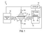
- FIG. 1 is a schematic diagram of an inkjet printer having a fluid emitter that sprays a fluid onto an ink image formed on one side of a print medium in a simplex print mode.
- FIG. 2 is a schematic diagram of the inkjet printer of FIG. 1 with fluid emitters that spray fluid onto ink images formed on two sides of the print medium in a duplex print mode.
- FIG. 3 is a side view of a roller in a finishing unit that engages a print medium with a printed ink image.
- FIG. 4 is a block diagram of a process for operating an inkjet printer that sprays a fluid onto printed ink images.
- FIG. 5 is a block diagram of a process for adjusting an amount of fluid sprayed onto different regions of an ink image.
- FIG. 6 is an exemplary depiction of regions of an ink image that include different coverage densities.
- the term “printer” refers to any device that forms ink images on print media and includes photocopiers, facsimile machines, multifunction devices, as well as direct and indirect inkjet printers.
- An image receiving surface refers to any surface that receives ink drops, such as print media, which includes paper sheets or a continuous paper roll, and intermediate imaging surfaces, such as image drums or belts.
- coverage density refers to the ratio of the print medium covered by ink to the total area of a particular area of the medium that includes the covered area.
- the coverage density can be described as a percentage, with 100% coverage density meaning the area is fully covered in ink and 0% coverage density meaning the area is free of ink.
- a printed page includes areas that are printed with a 100% coverage density, and other areas that are left unprinted with a 0% coverage density.
- the printer can print an area with an intermediate coverage density by ejecting ink drops in a dithered pattern.
- the term “dither” refers to an operation for ejecting ink drops in a pattern that interleaves with blank portions of the receiving member.
- a common example of a dithered pattern is a “checkerboard” pattern where ink drops are placed on the image surface as alternating pixels that are interleaved with blank areas.
- Various dither patterns can be used to generate images with different coverage densities.
- FIG. 1 and FIG. 2 depict one embodiment of an inkjet printer 100 .
- FIG. 1 depicts the printer 100 operating in a simplex print mode to produce ink images on only one side of the web 120
- FIG. 2 depicts the printer 100 operating in a duplex print mode to produce ink images on two sides of the web 120 .
- the inkjet printer 100 includes a print engine 108 , fluid emitters 128 A and 128 B, and a finishing unit 136 .
- a controller 140 is operatively connected to the media transport 106 that moves the print medium 120 , which is depicted in FIG. 1 and FIG. 2 as a continuous media web, a print engine 108 , fluid emitters 128 A and 128 B, and the finishing unit 136 to direct a printing process.
- a print medium 120 moves through the print engine 108 , by the fluid emitters 128 A and 128 B, and through the finishing unit 136 in a process direction P.
- the media transport 106 can be configured with conveyor belts and other members to move individual media sheets through the printer 100 in the process direction P.
- the controller 140 can be implemented with general or specialized programmable processors that execute programmed instructions.
- the instructions and data required to perform the programmed functions are stored in memory associated with the processors or controllers.
- the processors, their memories, and interface circuitry configure the controllers and/or print engine to perform the functions, such as the difference minimization function, described above.
- These components can be provided on a printed circuit card or provided as a circuit in an application specific integrated circuit (ASIC).
- ASIC application specific integrated circuit
- Each of the circuits can be implemented with a separate processor or multiple circuits can be implemented on the same processor.
- the circuits can be implemented with discrete components or circuits provided in VLSI circuits.
- the circuits described herein can be implemented with a combination of processors, ASICs, discrete components, or VLSI circuits.
- the print engine 108 includes an inkjet array 112 and an optional duplexing unit 116 .
- the inkjet array 112 is formed from one or more printheads, each of which includes a plurality of inkjets.
- the printheads are arranged in a print zone, and the print medium 120 moves through the print zone in the process direction P.
- Each inkjet in the inkjet array 112 is configured to eject drops of a liquid ink onto a surface of the print medium 120 as the print medium moves through the print zone.
- the controller 140 During an imaging operation, the controller 140 generates electrical signals that activate the inkjets in the inkjet array 112 .
- the controller receives digital image data corresponding to one or more ink images that the print engine 108 prints onto the print medium 120 .
- the image data can include binary data in a rasterized image format, printer command data in a page description language (PDL), ASCII text data, or any other digital data format known to the art for controlling the formation of ink images in a printer.
- the controller 140 generates the electrical signals for operating the print engine 108 with reference to the received image data to form ink images on the web 120 .
- the electrical signals are used by the print engine to eject ink drops from selected inkjets in the inkjet array 112 at selected times to generate a two-dimensional pattern of ink drops on the surface of the print medium 120 as the print medium 120 moves through the print zone.
- ink image refers to any arrangement of ink formed on the print medium by one or more inkjets.
- An ink image includes both printed text and graphics, and can include one or more colors of ink.
- An ink image corresponding to a single printed page can include different regions incorporating text, graphics, photographs, or any other arrangement of ink formed by the inkjet array 112 .
- the print engine 108 and the inkjet array 112 are configured to form printed ink images using phase change ink.
- a phase change ink refers to any form of ink that is substantially solid at room temperature and substantially liquid when heated to a phase change ink melting temperature for jetting onto the imaging receiving surface.
- the phase change ink melting temperature can be any temperature that is capable of melting solid phase change ink into liquid or molten form. In one embodiment, the phase change ink melting temperature is approximately 70° C. to 140° C.
- the ink utilized in the imaging device can comprise UV curable gel ink. Gel ink is also heated to affect the viscosity of the ink before the ink is ejected by the inkjets of the printhead.
- the print engine 108 and inkjet array 112 include one or more heaters that melt the phase change ink for ejection onto the print medium 120 in the form of melted ink drops.
- the melted ink drops cool and solidify on the surface of the print medium 120 to form ink images.
- the print engine 108 can include additional heaters and pressure rollers to spread the ink drops on the surface of the print medium before the melted phase change ink solidifies.
- the printer 100 controls the temperature of the print medium 120 to enable the phase change ink printed images to solidify prior to the print medium 120 moving past the fluid emitters 128 A and 128 B in the process direction P.
- the print engine 108 prints an ink image 124 on only one surface of the print medium 120 .
- This mode of print engine operation is known as simplex print operation.
- the print engine 108 leaves the surface of a second side 122 of the print medium without an ink image.
- the print engine 108 operates in a duplex print mode to print ink images 124 and 126 on both sides of the print medium 120 .
- the duplexed ink images are typically aligned in the process direction P to correspond to two printed sides of a single page in a document.
- a duplexing unit (not shown) is included that inverts the print medium 120 and returns a second side of the print medium 120 past the inkjet array 112 for duplex printing before the print medium 120 passes the fluid emitters 128 A and 128 B.
- Another printer embodiment capable of duplex printing operation includes two print engines that each print an ink image on one side of the print medium 120 to produce a duplexed image before the print medium 120 passes the fluid emitters 128 A and 128 B.
- any printer configuration that ejects ink drops onto both sides of a media sheet is referred to as a duplex printer.
- many printers that are capable of printing in a duplex mode are also configurable to print in a simplex mode. Still other printer embodiments only print in a simplex mode.
- the fluid emitters 128 A and 128 B are positioned after the print engine 108 and before the finishing unit in the process direction P.
- the print medium passes between the fluid emitters 128 A and 128 B, and each fluid emitter is configured to spray a fluid 132 onto only one side of the print medium 120 .
- the fluid emitter 128 A sprays fluid 132 directly onto the ink image 124 on the printed side of the print medium 120
- fluid emitter 128 B sprays fluid 132 directly onto the non-imaged side 122 .
- the “direct spraying” of the fluid 132 describes operation of the fluid emitters 128 A and 128 B to spray the fluid 132 in a manner where substantially all of the fluid 132 follows a direct path to only one side of the print medium 120 .
- the fluid emitters 128 A and 128 B can be operated to apply different amounts of fluid 132 directly to different regions of ink images formed on the print medium 120 .
- the fluid 132 sprayed by the fluid emitters 128 A and 128 B is water.
- a pump or other pressurized source (not shown) supplies the water to one or more nozzles in the fluid emitters 128 A and 128 B.
- Each of the fluid emitters 128 A and 128 B is configured to spray the water 132 directly onto substantially all of the surface area of one side of the print medium 120 , including the entire surface of an ink image that is printed on the print medium 120 .
- the controller 140 is operatively connected to the fluid emitters 128 A and 128 B to control the spray of water 132 toward each side of the print medium 120 .
- the controller 140 selectively dilates and contracts outlets in the fluid emitters 128 A and 128 B to control the output rate of the water 132 through each of the fluid emitters 128 A and 128 B.
- the printer 100 sprays water 132 from the fluid emitter 128 A onto the ink image 124 formed on one side of the print medium 120 .
- the print medium 120 absorbs a portion of the water 132 .
- Another portion of the water 132 collects on an upper surface of the ink image 124 .
- the water formed on the ink image 124 reduces or eliminates offset of the ink image 124 from the print medium 120 as the finishing unit 136 processes the print medium 120 .
- the controller 140 operates the fluid emitter 128 B to spray water 132 onto the non-printed side 122 of the print medium 120 , while in other embodiments, the controller only operates the emitter 128 A to spray the fluid on only the side of the media printed with an ink image.
- Fluid may need to be sprayed on both sides of the print medium 120 to reduce local differences in the moisture content of the print medium 120 .
- uneven moisture content in the print medium 120 can result in curling, cockling, waviness, or other distortions to the shape of the print medium.
- the water 132 sprayed directly onto both sides of the print medium reduces or eliminates distortion of the print medium due to uneven moisture content.
- the controller 140 operates the fluid emitter 128 A to spray fluid 132 directly onto the ink image 124 and operates the fluid emitter 128 B to spray fluid 132 directly onto the ink image 126 at substantially the same time.
- the sprayed fluid 132 collects on the surface of both of the ink images 124 and 126 .
- the fluid on the surface of the ink images 124 and 126 reduces or eliminates offset from both of the ink images 124 and 126 as the finishing unit 136 processes the print medium 120 .
- both of the fluid emitters 128 A and 128 B operate substantially simultaneously to spray the fluid 132 directly onto either side of the print medium 120 .
- the controller 140 can vary an output rate of fluid 132 through each of the fluid emitters 128 A and 128 B while both of the fluid emitters spray fluid 132 .
- the controller 140 operates the fluid emitter 128 A to spray fluid 132 at a higher output rate than an output rate of the fluid emitter 128 B. Consequently, a larger amount of fluid 132 lands on the ink image 124 and the printed side of the print medium 120 than on the non-printed side 122 .
- the print medium 120 enters the finishing unit 136 after passing the fluid emitters 128 A and 128 B in the process direction P.
- the finishing unit 136 includes one or more rollers, baffles, trays, and other components that engage the print medium 120 .
- the finishing unit 136 can include one or more cutting devices that cut the continuous web into a plurality of printed sheets.
- the print medium 120 is an individual sheet, and the finishing unit stacks and collates multiple media sheets during a print job.
- FIG. 3 depicts an example of a roller in the finishing unit 136 and the print medium 120 .
- the print medium 120 moves in the process direction P to engage the surface of a roller 312 .
- a layer of the fluid 132 is formed on the surface of the ink image 124 .
- the surface of the roller 312 engages the fluid 132 instead of engaging the ink image 124 directly.
- the fluid 132 forms a barrier that reduces or eliminates adhesion and potential offset between the ink image 124 and the roller 312 .
- the fluid sprayed onto the surface of ink images in the printer 100 reduces or eliminates offset between the ink images and components in the finishing unit 136 . While FIG.
- the water 132 can also form as a plurality of drops that partially cover the surface of the ink image 124 .
- the water drops also form a barrier that reduces the size of contiguous areas of contact between the ink image 124 and the roller 312 . Consequently, the water drops also reduce adhesion and a likelihood of offset between the ink image 124 and the roller 312 .
- the fluid 132 is water. After the print medium 120 passes through the finishing unit 136 , any remaining water 132 evaporates from the surface of the ink image 124 .
- Other embodiments spray different fluids onto the ink images to form a barrier between the ink images and components in the finishing unit 136 .
- silicone can be sprayed onto the ink image to reduce or eliminate contamination of finishing units. The silicone formed on the ink images reduces adhesion between ink on the print medium and components in the finishing unit. The silicone evaporates from the surface of the printed ink images and the print medium after the finishing unit processes the print medium.
- FIG. 4 depicts a process 400 for printing images in an inkjet printer.
- a reference to the process 400 performing a function or action refers to a controller executing programmed instructions stored in a memory to operate one or more components of the printer to perform the function or action.
- Process 400 is described in conjunction with printer 100 for illustrative purposes.
- Process 400 begins by moving a print medium through a print zone (block 404 ) and ejecting ink drops onto a surface of the print medium to form an ink image (block 408 ).
- the media transport 106 moves the print medium 120 moves past the inkjet array 112 in the print engine 108 in the process direction P.
- the controller 140 generates electrical signals that operate the print engine 108 and the inkjet array 112 with reference to received digital image data.
- the inkjet array can be configured to eject melted phase change ink drops onto the print medium 112 .
- the printer 100 In a simplex print mode, the printer 100 only prints an ink image on one side of the print medium 120 during process 400 , instead of printing on two sides in a duplex mode (block 416 ).
- Process 400 continues as the print medium 420 moves past the fluid emitters 128 A and 128 B.
- the controller 140 activates at least one of the fluid emitters, such as fluid emitter 128 A in FIG. 1 , to spray fluid 132 onto the printed ink image 124 (block 420 ).
- the controller 128 optionally activates and deactivates the fluid emitter 128 A so that the fluid 132 is only sprayed onto sections of the media web that include ink images and not onto blank interstitial regions of the media web.
- the controller 140 can optionally activate the second fluid emitter, such as fluid emitter 128 B in FIG. 1 , to spray the fluid 132 onto the non-imaged side of the print medium 120 to balance the moisture content of the print medium 120 (block 424 ).
- the printer 100 prints an ink image on both sides of the print medium 120 during process 400 (block 416 ).
- the controller 140 activates inkjets to ejecting ink drops onto the second surface of the print medium to form a second ink image (block 428 ).
- the print engine 108 includes a duplexing unit to invert the print medium to pass the second side of the print medium past the inkjet ejectors 112 .
- a second inkjet array is located in the process direction P to print the second ink image onto the second side of the print medium 120 .
- the second ink image can be printed before, during, or after the printing of the first ink image.
- the controller 140 activates both of the fluid emitters 128 A and 128 B to spray fluid 132 onto the first printed ink image 124 and the second printed ink image 126 , respectively (block 432 ).
- the controller 128 optionally activates and deactivates the fluid emitters 128 A and 128 B so that the fluid 132 is only sprayed onto sections of the media web that include ink images and not onto blank interstitial regions of the media web.
- the fluid emitters 128 A and 128 B both spray the fluid 132 at substantially the same time as the print medium 120 moves in the process direction P.
- the printer 100 moves the print medium 120 into the finishing unit 136 (block 440 ).
- the fluid 132 forms a barrier over the printed ink image 124 in a simplex print mode, and over ink images 124 and 126 in the duplex print mode to reduce or eliminate offset of the ink from the print medium as the finishing unit 136 processes the print medium 120 .
- the controller 140 is configured to adjust the operation of the fluid emitters 128 A and 128 B to adjust an output rate of the fluid 132 onto both sides of the print medium 120 .
- the amount of fluid 132 that sprays onto the print medium 120 is proportional to the output rate.
- FIG. 5 depicts a process 500 for controlling an amount of fluid that is sprayed onto the print medium.
- Process 500 is performed in conjunction with process 400 , and a reference to the process 500 performing a function or action refers to a controller executing programmed instructions stored in a memory to operate one or more components of the printer to perform the function or action.
- Process 500 is described in conjunction with printer 100 for illustrative purposes.
- the controller 140 identifies regions of an ink image that have different coverage densities (block 504 ). In one embodiment, the controller 140 identifies the coverage densities in different regions of the ink image with reference to the same digital image data that the controller uses to print the ink image.
- FIG. 6 depicts an example of a single page printed on the print medium 120 . In the example of FIG. 6 , the controller 140 identifies three regions 604 , 608 , and 612 , each of which has different image densities. In one embodiment, the controller 140 segments the image data into the different regions based on an average coverage density over the region of the printed image. For example, in FIG. 6 , the region 604 can include black text.
- the black text has a coverage density of 100%, while blank areas around the text have a coverage density of 0%.
- the average coverage density of the entire region 604 is an intermediate percentage between 0% and 100%.
- the ink image includes a photographic image that has 100% coverage over the entire region.
- the region 612 includes a dithered printed pattern having another intermediate coverage density.
- the example of FIG. 6 is merely illustrative, and the controller 140 can identify fewer or greater numbers of regions in the image data. Additionally, some ink images include a substantially uniform coverage density over the entire image. The controller 140 identifies a single coverage density for the entire ink image for the ink images with uniform coverage densities.
- the controller 140 adjusts the output rate of the fluid emitter 128 A or 128 B that sprays the fluid 132 onto the ink image (block 508 ).
- the controller 140 selectively dilates and contracts an output valve in each of the fluid emitters 128 A and 128 B to control the output rate.
- the controller 140 adjusts the output rate of the fluid emitters 128 A and 128 B in synchronization with the media transport 106 so that the selected amount of fluid 132 lands on each region of the print medium 120 as the print medium 120 passes the fluid emitters 128 A and 128 B.
- the controller 140 identifies the output rate for each of the fluid emitters 128 A and 128 B with reference to a look up table (LUT) stored in a memory.
- the LUT includes predetermined fluid output rates for the coverage densities identified in the image data.
- the controller 140 increases the fluid output rate through the fluid emitters 128 A and 128 B when spraying the fluid 132 onto regions of the ink image that have a higher coverage densities. This type of operation helps ensure that a sufficient amount of the fluid 132 covers the surface of the ink image to reduce or eliminate offset when the print medium is processed in the finishing unit 136 .
- the fluid output rate and amount of fluid sprayed on the print medium 120 is decreased when spraying the fluid 132 onto regions of the ink image that have lower coverage densities to prevent distortion of the print medium 120 due to absorption of the fluid 132 .
Abstract
Description
Claims (6)
Priority Applications (1)
| Application Number | Priority Date | Filing Date | Title |
|---|---|---|---|
| US13/358,755 US8721019B2 (en) | 2012-01-26 | 2012-01-26 | Apparatus and method for treatment of printed ink images |
Applications Claiming Priority (1)
| Application Number | Priority Date | Filing Date | Title |
|---|---|---|---|
| US13/358,755 US8721019B2 (en) | 2012-01-26 | 2012-01-26 | Apparatus and method for treatment of printed ink images |
Publications (2)
| Publication Number | Publication Date |
|---|---|
| US20130194332A1 US20130194332A1 (en) | 2013-08-01 |
| US8721019B2 true US8721019B2 (en) | 2014-05-13 |
Family
ID=48869840
Family Applications (1)
| Application Number | Title | Priority Date | Filing Date |
|---|---|---|---|
| US13/358,755 Expired - Fee Related US8721019B2 (en) | 2012-01-26 | 2012-01-26 | Apparatus and method for treatment of printed ink images |
Country Status (1)
| Country | Link |
|---|---|
| US (1) | US8721019B2 (en) |
Families Citing this family (2)
| Publication number | Priority date | Publication date | Assignee | Title |
|---|---|---|---|---|
| US9955828B2 (en) * | 2012-08-31 | 2018-05-01 | Gmat Ventures, Llc | Automatic raising and controlled lowering of a toilet seat |
| EP3955103A1 (en) * | 2020-08-13 | 2022-02-16 | Canon Kabushiki Kaisha | Digital process controller and a method for controlling a production process of a complex composed end product |
Citations (15)
| Publication number | Priority date | Publication date | Assignee | Title |
|---|---|---|---|---|
| US3661619A (en) | 1969-04-17 | 1972-05-09 | Frye Ind Inc | Printing process employing moisture |
| US5764263A (en) * | 1996-02-05 | 1998-06-09 | Xerox Corporation | Printing process, apparatus, and materials for the reduction of paper curl |
| US5850589A (en) * | 1997-09-29 | 1998-12-15 | Xerox Corporation | Sheet moisture replacement system using water jet technology |
| US6176574B1 (en) * | 1998-05-22 | 2001-01-23 | Eastman Kodak Company | Printing apparatus with spray bar for improved durability |
| US6259887B1 (en) | 1998-08-11 | 2001-07-10 | Fuji Xerox Co., Ltd. | Image forming apparatus |
| US6435678B1 (en) * | 1998-05-22 | 2002-08-20 | Eastman Kodak Company | Waterfast ink jet images treated with hardeners |
| US6484009B2 (en) | 2000-06-20 | 2002-11-19 | Oki Data Corporation | Electrophotographic printer having offset prevention |
| US20040196324A1 (en) * | 2002-05-14 | 2004-10-07 | Tschida Mark J | High-speed, high-resolution color printing apparatus and method |
| US20060087700A1 (en) * | 2004-10-21 | 2006-04-27 | Kazuyoshi Kishi | Image processing apparatus |
| US20090034023A1 (en) * | 2002-06-24 | 2009-02-05 | Nikon Corporation | Image scanning system |
| US20090256896A1 (en) | 2008-04-09 | 2009-10-15 | Xerox Corporation | Ink-jet printer and method for decurling cut sheet media prior to ink-jet printing |
| US20100192685A1 (en) * | 2009-02-02 | 2010-08-05 | Xerox Corporation | Apparatus And Method For Detecting Ink In A Reservoir |
| US20100321434A1 (en) * | 2009-06-23 | 2010-12-23 | Canon Kabushiki Kaisha | Printing apparatus and image processing method |
| US20110141180A1 (en) | 2009-12-10 | 2011-06-16 | Kabushiki Kaisha Toshiba | Image forming apparatus and method of inkjet having humidity adjustment mechanism |
| US20110206841A1 (en) | 2006-05-22 | 2011-08-25 | Jordi Sabater Vilella | Method and device for conditioning paper |
-
2012
- 2012-01-26 US US13/358,755 patent/US8721019B2/en not_active Expired - Fee Related
Patent Citations (16)
| Publication number | Priority date | Publication date | Assignee | Title |
|---|---|---|---|---|
| US3661619A (en) | 1969-04-17 | 1972-05-09 | Frye Ind Inc | Printing process employing moisture |
| US5764263A (en) * | 1996-02-05 | 1998-06-09 | Xerox Corporation | Printing process, apparatus, and materials for the reduction of paper curl |
| US5850589A (en) * | 1997-09-29 | 1998-12-15 | Xerox Corporation | Sheet moisture replacement system using water jet technology |
| US6176574B1 (en) * | 1998-05-22 | 2001-01-23 | Eastman Kodak Company | Printing apparatus with spray bar for improved durability |
| US6435678B1 (en) * | 1998-05-22 | 2002-08-20 | Eastman Kodak Company | Waterfast ink jet images treated with hardeners |
| US6259887B1 (en) | 1998-08-11 | 2001-07-10 | Fuji Xerox Co., Ltd. | Image forming apparatus |
| US6484009B2 (en) | 2000-06-20 | 2002-11-19 | Oki Data Corporation | Electrophotographic printer having offset prevention |
| US20040196324A1 (en) * | 2002-05-14 | 2004-10-07 | Tschida Mark J | High-speed, high-resolution color printing apparatus and method |
| US20090034023A1 (en) * | 2002-06-24 | 2009-02-05 | Nikon Corporation | Image scanning system |
| US20060087700A1 (en) * | 2004-10-21 | 2006-04-27 | Kazuyoshi Kishi | Image processing apparatus |
| US20110206841A1 (en) | 2006-05-22 | 2011-08-25 | Jordi Sabater Vilella | Method and device for conditioning paper |
| US20090256896A1 (en) | 2008-04-09 | 2009-10-15 | Xerox Corporation | Ink-jet printer and method for decurling cut sheet media prior to ink-jet printing |
| US8038280B2 (en) | 2008-04-09 | 2011-10-18 | Xerox Corporation | Ink-jet printer and method for decurling cut sheet media prior to ink-jet printing |
| US20100192685A1 (en) * | 2009-02-02 | 2010-08-05 | Xerox Corporation | Apparatus And Method For Detecting Ink In A Reservoir |
| US20100321434A1 (en) * | 2009-06-23 | 2010-12-23 | Canon Kabushiki Kaisha | Printing apparatus and image processing method |
| US20110141180A1 (en) | 2009-12-10 | 2011-06-16 | Kabushiki Kaisha Toshiba | Image forming apparatus and method of inkjet having humidity adjustment mechanism |
Also Published As
| Publication number | Publication date |
|---|---|
| US20130194332A1 (en) | 2013-08-01 |
Similar Documents
| Publication | Publication Date | Title |
|---|---|---|
| US7360887B2 (en) | Image forming apparatus and method | |
| US8256857B2 (en) | System and method for compensating for small ink drop size in an indirect printing system | |
| US8955937B2 (en) | System and method for inoperable inkjet compensation | |
| JP5956824B2 (en) | Image forming apparatus | |
| US9193177B1 (en) | System for reducing cockle in media printed by an inkjet printer | |
| KR101875965B1 (en) | Printer | |
| JP2012143874A (en) | Inkjet recording apparatus | |
| US9434155B1 (en) | Method and system for printhead alignment based on print medium width | |
| JP2008183719A (en) | Liquid droplet delivering apparatus and program | |
| US8721019B2 (en) | Apparatus and method for treatment of printed ink images | |
| JP2010105306A (en) | Ink ejection device and its control method | |
| US9033487B2 (en) | Device and method for addressable spray-on application of release agent to continuous feed media | |
| US8911052B2 (en) | Inkjet recording machine | |
| JP5035036B2 (en) | Recording device | |
| KR101959573B1 (en) | Printer | |
| JP2006076129A (en) | Inkjet recorder | |
| US8240813B2 (en) | Directed flow drip bib for an inkjet printhead | |
| JP2011201154A (en) | Liquid ejector | |
| US8031372B2 (en) | System and method for distributing image values of a color separation | |
| US9522548B2 (en) | Inkjet recording device | |
| US8827439B2 (en) | Self-cleaning media perforator | |
| JP2009248428A (en) | Ink jet recording method and ink jet recording apparatus | |
| US8764151B2 (en) | System and method for preserving edges while enabling inkjet correction within an interior of an image | |
| US8540357B2 (en) | Dithered printing of clear ink to reduce rub and offset | |
| JP2010094993A (en) | System and method for recording image by single pass for serially arranged multiple printheads |
Legal Events
| Date | Code | Title | Description |
|---|---|---|---|
| AS | Assignment |
Owner name: XEROX CORPORATION, CONNECTICUT Free format text: ASSIGNMENT OF ASSIGNORS INTEREST;ASSIGNOR:MEYER, HENRY ALAN;REEL/FRAME:027599/0582 Effective date: 20120126 |
|
| FEPP | Fee payment procedure |
Free format text: PAYOR NUMBER ASSIGNED (ORIGINAL EVENT CODE: ASPN); ENTITY STATUS OF PATENT OWNER: LARGE ENTITY |
|
| STCF | Information on status: patent grant |
Free format text: PATENTED CASE |
|
| MAFP | Maintenance fee payment |
Free format text: PAYMENT OF MAINTENANCE FEE, 4TH YEAR, LARGE ENTITY (ORIGINAL EVENT CODE: M1551) Year of fee payment: 4 |
|
| FEPP | Fee payment procedure |
Free format text: MAINTENANCE FEE REMINDER MAILED (ORIGINAL EVENT CODE: REM.); ENTITY STATUS OF PATENT OWNER: LARGE ENTITY |
|
| LAPS | Lapse for failure to pay maintenance fees |
Free format text: PATENT EXPIRED FOR FAILURE TO PAY MAINTENANCE FEES (ORIGINAL EVENT CODE: EXP.); ENTITY STATUS OF PATENT OWNER: LARGE ENTITY |
|
| STCH | Information on status: patent discontinuation |
Free format text: PATENT EXPIRED DUE TO NONPAYMENT OF MAINTENANCE FEES UNDER 37 CFR 1.362 |
|
| FP | Lapsed due to failure to pay maintenance fee |
Effective date: 20220513 |