US8734003B2 - Micro-chemical mixing - Google Patents
Micro-chemical mixing Download PDFInfo
- Publication number
- US8734003B2 US8734003B2 US11/319,865 US31986505A US8734003B2 US 8734003 B2 US8734003 B2 US 8734003B2 US 31986505 A US31986505 A US 31986505A US 8734003 B2 US8734003 B2 US 8734003B2
- Authority
- US
- United States
- Prior art keywords
- droplet
- chemical species
- recited
- substrate
- species
- Prior art date
- Legal status (The legal status is an assumption and is not a legal conclusion. Google has not performed a legal analysis and makes no representation as to the accuracy of the status listed.)
- Expired - Fee Related, expires
Links
Images


Classifications
-
- B—PERFORMING OPERATIONS; TRANSPORTING
- B01—PHYSICAL OR CHEMICAL PROCESSES OR APPARATUS IN GENERAL
- B01L—CHEMICAL OR PHYSICAL LABORATORY APPARATUS FOR GENERAL USE
- B01L3/00—Containers or dishes for laboratory use, e.g. laboratory glassware; Droppers
- B01L3/02—Burettes; Pipettes
- B01L3/0241—Drop counters; Drop formers
-
- B—PERFORMING OPERATIONS; TRANSPORTING
- B01—PHYSICAL OR CHEMICAL PROCESSES OR APPARATUS IN GENERAL
- B01F—MIXING, e.g. DISSOLVING, EMULSIFYING OR DISPERSING
- B01F31/00—Mixers with shaking, oscillating, or vibrating mechanisms
- B01F31/65—Mixers with shaking, oscillating, or vibrating mechanisms the materials to be mixed being directly submitted to a pulsating movement, e.g. by means of an oscillating piston or air column
-
- B—PERFORMING OPERATIONS; TRANSPORTING
- B01—PHYSICAL OR CHEMICAL PROCESSES OR APPARATUS IN GENERAL
- B01F—MIXING, e.g. DISSOLVING, EMULSIFYING OR DISPERSING
- B01F33/00—Other mixers; Mixing plants; Combinations of mixers
- B01F33/30—Micromixers
- B01F33/302—Micromixers the materials to be mixed flowing in the form of droplets
- B01F33/3021—Micromixers the materials to be mixed flowing in the form of droplets the components to be mixed being combined in a single independent droplet, e.g. these droplets being divided by a non-miscible fluid or consisting of independent droplets
-
- B—PERFORMING OPERATIONS; TRANSPORTING
- B01—PHYSICAL OR CHEMICAL PROCESSES OR APPARATUS IN GENERAL
- B01F—MIXING, e.g. DISSOLVING, EMULSIFYING OR DISPERSING
- B01F33/00—Other mixers; Mixing plants; Combinations of mixers
- B01F33/30—Micromixers
- B01F33/3031—Micromixers using electro-hydrodynamic [EHD] or electro-kinetic [EKI] phenomena to mix or move the fluids
-
- Y—GENERAL TAGGING OF NEW TECHNOLOGICAL DEVELOPMENTS; GENERAL TAGGING OF CROSS-SECTIONAL TECHNOLOGIES SPANNING OVER SEVERAL SECTIONS OF THE IPC; TECHNICAL SUBJECTS COVERED BY FORMER USPC CROSS-REFERENCE ART COLLECTIONS [XRACs] AND DIGESTS
- Y10—TECHNICAL SUBJECTS COVERED BY FORMER USPC
- Y10T—TECHNICAL SUBJECTS COVERED BY FORMER US CLASSIFICATION
- Y10T436/00—Chemistry: analytical and immunological testing
- Y10T436/25—Chemistry: analytical and immunological testing including sample preparation
Definitions
- the present invention is directed, in general, to a device and a method for mixing two or more species within a droplet.
- Embodiments of the present invention overcome these problems by providing a device and method that facilitates the movement and mixing of small volumes of fluids.
- the present invention provides a method.
- the method comprises providing a droplet having a first chemical species and a second chemical species on a substrate, and applying a voltage across the droplet to physically repeatedly deform the droplet.
- the applying causes the droplet to move with respect to an object located therein and at least partially mix the first chemical species and the second chemical species.
- the method includes providing a droplet over a substrate, injecting a chemical species within the droplet and applying a voltage across the droplet.
- injecting and applying use a same object.
- the device includes a substrate having a droplet thereover, and an electrical source coupleable to the substrate, the electrical source configured to apply a voltage between the substrate and the droplet using an electrode, wherein the electrode has a first portion and a second portion non-symmetric to the first portion, the first and second portions defined by a plane located normal to a longitudinal axis and through a midpoint of a length of the electrode.
- FIGS. 1A thru 1 E illustrate cross-sectional views of a device while undergoing a process for mixing two or more species within a droplet in accordance with the principles of the present invention
- FIGS. 2A thru 2 D illustrate different objects, in this embodiment electrodes, that might be used in place of the object illustrated in FIGS. 1A thru 1 E;
- FIG. 3 illustrates an alternative embodiment of an object that might be used with the methodology discussed above with respect to FIGS. 1A thru 1 E;
- FIG. 4 illustrates a cross-sectional view of an alternative embodiment of a device while undergoing a process for mixing two or more species within a droplet in accordance with the principles of the present invention
- FIG. 5 illustrates an alternative embodiment of a device in accordance with the principles of the present invention
- FIG. 6 illustrates a cross-sectional view of an alternative embodiment of a device while undergoing a process for mixing two or more species within a droplet in accordance with the principles of the present invention
- FIG. 7 illustrates one embodiment of a mobile diagnostic device in accordance with the principles of the present invention.
- the vertical position of a droplet can be made to oscillate on certain kinds of substrates.
- the vertical position of the droplet can be made to oscillate on a conductive substrate having fluid-support-structures thereon.
- the application of a voltage between the substrate and the droplet may cause the droplet to alternate between a state with a high contact angle (e.g., a less flattened configuration or a non-wetted state) and a state with a lower contact angle (e.g., a more flattened configuration or a wetted state).
- the substrate comprises a pattern of fluid-support-microstructures, the applied voltage causing a surface of the droplet to move between tops of the fluid-support-microstructures and the substrate on which the microstructures are located. Such movements cause the droplet to move between effective more flattened and less flattened states, respectively.
- the droplet in this manner promotes mixing of two or more species (e.g., chemical species) within the droplet.
- the repeated deformation of the droplet can induce motion within the droplet, thereby promoting mixing of the two or more species of fluids.
- the object may for example be an electrode used to provide the voltage.
- FIGS. 1A thru 1 E illustrated are cross-sectional views of a device 100 while a droplet undergoes a process for mixing two or more species therein in accordance with the principles of the present invention.
- the device 100 of FIGS. 1A thru 1 E initially includes a substrate 110 .
- the substrate 110 may be any layer located within a device and having properties consistent with the principles of the present invention.
- the substrate 110 is a conductive substrate.
- the conductive substrate 110 comprises silicon, metal silicide, or both.
- the conductive substrate 110 comprises a metal silicide such as cobalt silicide.
- metal silicides such as tungsten silicide or nickel silicide, or alloys thereof, or other electrically conductive materials, such as metal films, can be used.
- an insulator layer 115 may be disposed thereon.
- one or both of the substrate 110 or insulator layer 115 has hydrophobic properties.
- one or both of the substrate 110 or insulator layer 115 might at least partially comprise a low-surface-energy material.
- a low-surface-energy material refers to a material having a surface energy of about 22 dyne/cm (about 22 ⁇ 10 ⁇ 5 N/cm) or less.
- the low-surface-energy material comprises a fluorinated polymer, such as polytetrafluoroethylene, and has a surface energy ranging from about 18 to about 20 dyne/cm.
- a droplet 120 Located over the substrate 110 in the embodiment shown, and the insulator layer 115 if present, is a droplet 120 .
- the droplet 120 may comprise a variety of different species and fluid volumes while staying within the scope of the present invention. In one exemplary embodiment of the present invention, however, the droplet 120 has a fluid volume of about 100 microliters or less. It has been observed that the methodology of the present invention is particularly useful for mixing different species located within droplets 120 having fluid volumes of about 100 microliters or less. Nevertheless, the present invention should not be limited to any specific fluid volume.
- first species 130 Located within the droplet 120 in the embodiments of FIGS. 1A thru 1 E are a first species 130 and a second species 135 .
- the first species 130 is denoted as ( ⁇ ) and the second species is denoted as (*).
- the first species 130 may be a diluent or a reactant.
- the second species 135 may be a diluent or a reactant.
- the first species 130 is a first reactant and the second species 135 is a second reactant, both of which are suspended within a third species, such as a diluent.
- Some preferred embodiments of the device 100 also comprise an electrical source 140 (e.g., an AC or DC voltage source) coupled to the substrate 110 and configured to apply a voltage between the substrate 110 and the droplet 120 located thereover.
- the electrical source 140 uses an object 150 , such as an electrode, to apply the voltage. While the embodiment of FIGS. 1A thru 1 E illustrates that the object 150 is located above the substrate 110 , other embodiments exist wherein the object 150 contacts the droplet 120 from another location, such as from below the droplet 120 . Those skilled in the art understand how to configure such an alternative embodiment. Moreover, as will be discussed more fully below, the object 150 may take on a number of different configurations and remain within the purview of the present invention.
- the first species 130 and the second species 135 may be at least partially mixed within the droplet 120 using the inventive aspects of the present invention.
- the droplet is positioned in its less flattened state. For instance, because substantially no voltage is applied between the substrate 110 and the droplet 120 , the droplet is in its natural configuration.
- the first species 130 and the second species 135 located within the droplet of FIG. 1A are substantially, if not completely, separated from one another.
- FIG. 1B illustrated is the device 100 of FIG. 1A , after applying a non-zero voltage between the substrate 110 and the droplet 120 using the electrical source 140 and the object 150 .
- the droplet 120 moves to a flattened state, and thus is in its deformed configuration. It is the movement of the object 150 within the droplet 120 that is believed to promote the mixing of the first species 130 and the second species 135 . It should be noted, however, that other phenomena might be responsible for at least a portion of the mixing.
- the electrical source 140 is configured to apply a voltage ranging from about 1 to about 50 Volts. It is sometimes desirable for the voltage to be applied as a brief pulse so that the droplet 120 after becoming flattened can bounce back up to its less flattened state.
- the applied voltage is a series of voltage pulses applied at a rate in the range from about 1 to 100 Hertz, and more preferably from about 10 to 30 Hertz.
- the applied voltage is an AC voltage.
- the AC voltage has a frequency in the range from about 1 to about 100 Hertz.
- One cycle of droplet oscillation is defined to occur when the droplet 120 makes a round-trip change from the less flattened state to the more flattened state and back up to the less flattened state, or from the more flattened state to the less flattened state and back down to the more flattened state.
- the first species 130 and the second species 135 in the embodiment of FIG. 1B are slightly more mixed within the droplet 120 than the first species 130 and second species 135 in the droplet 120 of FIG. 1A .
- FIG. 1C illustrated is the device 100 of FIG. 1B after removing the voltage being applied via the electrical source 140 and object 150 .
- the droplet 120 substantially returns to its less flattened state, and has therefore made one complete cycle of movement.
- the movement from the more flattened state of FIG. 1B to the less flattened state of FIG. 1C may promote additional mixing.
- the first species 130 and second species 135 may be more mixed in the droplet 120 of FIG. 1C than the droplet 120 of FIG. 1B .
- the droplet 120 undergoes another cycle of movement, thus further promoting the mixing of the first species 130 and second species 135 therein.
- the droplet 120 may repeatedly be deformed, until a desired amount of mixing between the first species 130 and the second species 135 has occurred.
- the number of cycles, and thus the amount of mixing between the first species 130 and the second species 135 may be based upon one or both of a predetermined number of cycles or a predetermined amount of time. In any event, addition mixing typically occurs with each cycle, at least until the first species 130 and second species 135 are completely mixed.
- the present invention uses the repeated deformation of the droplet 120 having the object 150 therein to accomplish mixing of the first species 130 and second species 135 within the droplet 120 . Accordingly, wherein most methods for mixing the species within the droplet would be based upon the relative movement of the object 150 with respect to the droplet 120 , the present invention is based upon the movement of the droplet 120 with respect to the object 150 . For instance, in most preferred embodiments the object 150 is fixed, and thus stationary, and it is the movement of the droplet 120 using the electrical source 140 that promotes the movement.
- the method disclosed herein provides what is believed to be unparalleled mixing for two or more species within a droplet. Namely, the method disclosed herein in capable of easily mixing two or more species that might be located within a droplet having a fluid volume of about 100 microliters or less. Prior to this method, easy mixing of such small volumes was difficult, at best.
- the object 150 is positioned asymmetric along the axis of motion of the droplet being physically distorted.
- the object 150 may be positioned a non-zero angle away from the direction of movement of the droplet during mixing. This non-zero angle might be used to introduce increased mixing.
- FIGS. 1A thru 1 E are droplet based micro fluidic system. It should be noted, however, that other embodiments might consist of micro channel based micro fluidic systems, wherein the droplet might be located within a channel and the mixing occurring within one or more channels, as opposed to that shown in FIGS. 1A thru 1 E. Those skilled in the art understand just how the inventive aspects of the present invention could be employed with such a micro channel based micro fluidic system.
- FIGS. 2A thru 2 D illustrated are different objects 200 , in this embodiment electrodes, that might be used in place of the object 150 illustrated in FIG. 1A thru 1 E.
- the objects 200 illustrated in FIGS. 2A thru 2 D each have a first portion 210 and a second portion 220 non-symmetric to the first portion 210 .
- the first and second portions 210 , 220 are defined by a plane 230 located normal to a longitudinal axis 240 and through a midpoint 250 of a length (l) of the object 200 .
- the first portion 210 located above the plane 230 is non-symmetric to the second portion 220 located below the plane 230 .
- the object 200 may take on many different shapes.
- the object 200 of FIG. 2A comprises an inverted T, or depending on the view, a disk disposed along a shaft.
- the object 200 of FIG. 2B comprises an L
- the object 200 of FIG. 2C comprises a propeller
- the object 200 of FIG. 2D comprises a helix.
- FIGS. 2A thru 2 D provide increased mixing when the droplet moves with respect to the object as discussed with respect to FIGS. 1A thru 1 E above, at least as compared to the symmetric object 150 illustrated in FIGS. 1A thru 1 E.
- FIG. 3 illustrated is an alternative embodiment of an object 300 that might be used with the methodology discussed above with respect to FIGS. 1A thru 1 E.
- the object 300 of FIG. 3 as compared to the objects 150 , 200 of FIGS. 1A thru 1 E and 2 A thru 2 D, respectively, comprises multiple vertical sections 310 .
- the vertical sections 310 attempt to create a swirling effect within the droplet, thereby providing superior mixing of the two or more species. While each of the vertical sections 310 illustrated in FIG. 3 are shown as helix structures, similar to the object 200 of FIG. 2D , other embodiments exist wherein each of the vertical sections 310 are similar to any one of the shapes illustrated in previous FIGURES, as well as other shapes neither disclosed nor shown.
- FIG. 4 illustrated is a cross-sectional view of an alternative embodiment of a device 400 while undergoing a process for mixing two or more species within a droplet in accordance with the principles of the present invention.
- the device 400 of FIG. 4 is substantially similar to the device 100 illustrated in FIGS. 1A thru 1 E, with the exception that multiple objects 450 a and 450 b are positioned at different locations within the droplet 420 .
- each one of the multiple objects 450 a and 450 b is an individually addressable electrode.
- each one of the multiple objects 450 a and 450 b may be connected to different electrical sources 440 a and 440 b , respectively, thereby providing the ability to address them individually.
- each one of the multiple objects 450 a and 450 b could be connected to the same electrical source 440 , whether it be a fixed or variable electrical source, and switches could be placed between the electrical source 440 and each one of the multiple objects 450 a and 450 b .
- the switches would allow for the ability to address each one of the multiple objects 450 a and 450 b individually.
- the device 400 of FIG. 4 might be operated by alternately applying a voltage between the multiple objects 450 a and 450 b . In such an operation, an additional in-plane oscillation of the droplet 420 between the multiple objects 450 a and 450 b might occur. Accordingly, wherein the device 100 of FIGS. 1A thru 1 E might only cause the droplet 120 to move normal to the surface on which it rests, the device 400 of FIG. 4 might cause the droplet 420 to have this additional in-plane movement (e.g., along the surface on which it rests). As those skilled in the art appreciate, this additional in-plane movement may induce increased mixing, at least as compared to the movement created in the droplet 120 of FIGS. 1A thru 1 E.
- a voltage to object C such as is illustrated with respect to FIGS. 1A thru 1 E
- an in-plane movement of the droplet by applying an alternating voltage between objects A and E or B and D (such as is illustrated with respect to FIG. 4 above)
- induce a spinning movement of the droplet by sequentially applying a voltage to objects A, B, E and D.
- other complex geometries might provide even more significant mixing.
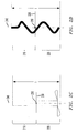
- FIG. 5 illustrated is an alternative embodiment of a device 500 in accordance with the principles of the present invention.
- the embodiment of the device 500 includes a substrate 510 , an insulator layer 515 , a droplet 520 (in both a less flattened state 520 a and a more flattened state 520 b ), an electrical source 540 and an object 550 .
- the object 550 is both configured to act as a hollow needle, and thus is configured to supply one or more species 560 to the droplet 520 , and well as configured to apply a voltage across the droplet 520 .
- the object 550 is an electrode also configured as a hollow needle, or vice-versa.
- each of the shapes illustrated in FIGS. 2A thru 2 D could be configured as a needle, thus providing both functions.
- Other shapes could also provide both functions and remain within the purview of the present invention.
- the object 550 could comprise a plurality of fluid channels to provide a plurality of different species 560 to the droplet 520 .
- the object 550 comprises a cluster of different needles, each different needle having its own fluid channel configured to provide a different species 560 .
- the object 550 comprises a single needle, however the single needle has a plurality of different fluid channels for providing the different species 560 .
- Other configurations which are not disclosed herein for brevity, could nevertheless also be used to introduce different species 560 within the droplet 520 .
- the above-discussed embodiments are particularly useful wherein there is a desire to keep the different species separate from one another, such as wherein the two species might undesirably react with one another.
- the device 500 including the object 550 may, therefore, be used to include any one or a collection of species 560 within the droplet 520 .
- the object 550 may, in addition to the ability to provide one or more species 560 within the droplet 520 , also function as an electrode to move the droplet 520 using electrowetting, mix two or more species within the droplet 520 using the process discussed above with respect to FIGS. 1A thru 1 E, or any other known or hereafter discovered process.
- FIG. 6 illustrated is a cross-sectional view of an alternative embodiment of a device 600 while undergoing a process for mixing two or more species within a droplet in accordance with the principles of the present invention.
- the device 600 of FIG. 6 initially includes a substrate 610 .
- the device 600 also includes fluid-support-structures 612 that are located over the substrate 610 .
- Each of the fluid-support-structures 612 at least in the embodiment shown, has at least one dimension of about 1 millimeter or less, and in some cases, about 1 micron or less.
- the fluid-support-structures 612 may comprise microstructures, nanostructures, or both microstructure and nanostructures.
- the fluid-support-structures 612 are laterally separated from each other.
- the fluid-support-structures 612 depicted in FIG. 6 are post-shaped, and more specifically, cylindrically shaped posts.
- the term post, as used herein, includes any structures having round, square, rectangular or other cross-sectional shapes.
- the fluid-support-structures 612 form a uniformly spaced array.
- the spacing is non-uniform.
- the spacing can be progressively decreased from about 10 microns to about 1 micron in a dimension.
- the fluid-support-structures 612 are electrically coupled to the substrate 610 . Moreover, each fluid-support-structure 612 is coated with an electrical insulator 615 .
- One suitable insulator material for the electrical insulator 615 is silicon dioxide.
- Exemplary fluid-support micro-structures and patterns thereof are described in U.S. Patent Application Publs.: 20050039661 of Avinoam Kornblit et al. (publ'd Feb. 24, 2005), U.S. Patent Application Publ. 20040191127 of Avinoam Kornblit et al. (publ'd Sep. 30, 2004), and U.S. Patent Application Publ. 20050069458 of Marc S. Hodes et al. (publ'd Mar. 31, 2005).
- the above three published U.S. Patent Applications are incorporated herein in their entirety.
- the device 600 of FIG. 6 further includes a droplet 620 located over the substrate 610 and the fluid-support-structures 612 .
- the droplet 620 is resting on a top surface of the fluid-support-structures 612 .
- the device 600 may further include an electrical source 640 and an object 650 .
- the substrate 610 , electrical insulator 615 , droplet 620 , electrical source 640 and object 650 may be similar to their respective features discussed above with regard to previous FIGUREs.
- the device 600 may be configured to oscillate the droplet 620 between the tops of the fluid-support-structures 612 and the substrate 610 , when a voltage is applied between the substrate 610 and the droplet 620 using the electrical source 640 and the object 650 .
- the device 600 can be configured to move the droplet 620 vertically, such that a lower surface of the droplet 620 moves back and forth between the tops of the fluid-support-structures 612 and the substrate 610 in a repetitive manner.
- FIG. 7 illustrated is one embodiment of a mobile diagnostic device 700 in accordance with the principles of the present invention.
- the mobile diagnostic device 700 illustrated in FIG. 7 initially includes a sample source region 710 and a chemical analysis region 720 .
- the sample source region 710 may include a plurality of droplets 730 , in this instance four droplets 730 a , 730 b , 730 c , and 730 d .
- the chemical analysis region 720 may include a plurality of both blank pixels 740 and reactant pixels 750 .
- the device 700 of FIG. 7 may operate by moving the droplets 730 across the chemical analysis region 720 , for example using electrowetting.
- a voltage may be applied across the substrate and the droplet 730 , thereby causing the droplet 730 to move to a more flattened state (e.g., wetted state in certain embodiments), and thus come into contact with the reactant located within that particular reactant pixel.
- the reactant in the pixel may be of a liquid form or a solid form.
- the reactant may be in a solid form, and thus dissolved or adsorbed by the droplet 730 .
- the droplet 730 c is initially located at a position 1 . Thereafter, the droplet 730 c is moved laterally using any known or hereafter discovered process wherein it undergoes an induced reaction 760 at position 2 .
- the induced reaction 760 in this embodiment, is initiated by applying a non-zero voltage between the substrate and the droplet 730 c , thereby causing the droplet 730 c to move to a more flattened state, and thus come into contact with the reactant in that pixel. Thereafter, as shown, the droplet 730 c could be moved to a position 3 , wherein it undergoes another induced reaction 770 .
- the droplets 730 may be repeatedly deformed in accordance with the principles discussed above with respect to FIGS. 1A thru 1 E. Accordingly, the reactant acquired during the induced reactions 760 , 770 , may be easily mixed using the process originally discussed above with respect to FIGS. 1A thru 1 E.
- each of the droplets 730 has its own object, and thus the droplets can be independently repeatedly deformed.
- each of the objects could be coupled to an independent AC voltage supply, or alternatively to the same AC voltage supply, to induce the mixing.
- Each of the mentioned objects could also be configured as a needle, and thus provide additional reactant species to the drops, such as discussed above with respect to FIG. 5 .
- Those skilled in the art understand the other ideas that might be used with the device 700 .
Abstract
Description

By using the combination of these five independent objects (e.g., electrodes A, B, C, D and E) one can either induce normal up and down movement of the droplet by applying a voltage to object C (such as is illustrated with respect to
Claims (21)
Priority Applications (2)
| Application Number | Priority Date | Filing Date | Title |
|---|---|---|---|
| US11/319,865 US8734003B2 (en) | 2005-09-15 | 2005-12-27 | Micro-chemical mixing |
| US14/247,791 US9839908B2 (en) | 2005-09-15 | 2014-04-08 | Micro-chemical mixing |
Applications Claiming Priority (2)
| Application Number | Priority Date | Filing Date | Title |
|---|---|---|---|
| US11/227,759 US8721161B2 (en) | 2005-09-15 | 2005-09-15 | Fluid oscillations on structured surfaces |
| US11/319,865 US8734003B2 (en) | 2005-09-15 | 2005-12-27 | Micro-chemical mixing |
Related Parent Applications (1)
| Application Number | Title | Priority Date | Filing Date |
|---|---|---|---|
| US11/227,759 Continuation-In-Part US8721161B2 (en) | 2005-09-15 | 2005-09-15 | Fluid oscillations on structured surfaces |
Related Child Applications (1)
| Application Number | Title | Priority Date | Filing Date |
|---|---|---|---|
| US14/247,791 Division US9839908B2 (en) | 2005-09-15 | 2014-04-08 | Micro-chemical mixing |
Publications (2)
| Publication Number | Publication Date |
|---|---|
| US20070056853A1 US20070056853A1 (en) | 2007-03-15 |
| US8734003B2 true US8734003B2 (en) | 2014-05-27 |
Family
ID=46325169
Family Applications (2)
| Application Number | Title | Priority Date | Filing Date |
|---|---|---|---|
| US11/319,865 Expired - Fee Related US8734003B2 (en) | 2005-09-15 | 2005-12-27 | Micro-chemical mixing |
| US14/247,791 Active 2026-08-08 US9839908B2 (en) | 2005-09-15 | 2014-04-08 | Micro-chemical mixing |
Family Applications After (1)
| Application Number | Title | Priority Date | Filing Date |
|---|---|---|---|
| US14/247,791 Active 2026-08-08 US9839908B2 (en) | 2005-09-15 | 2014-04-08 | Micro-chemical mixing |
Country Status (1)
| Country | Link |
|---|---|
| US (2) | US8734003B2 (en) |
Cited By (3)
| Publication number | Priority date | Publication date | Assignee | Title |
|---|---|---|---|---|
| US9681552B2 (en) | 2005-09-15 | 2017-06-13 | Alcatel Lucent | Fluid oscillations on structured surfaces |
| US9839908B2 (en) | 2005-09-15 | 2017-12-12 | Alcatel Lucent | Micro-chemical mixing |
| US10826065B2 (en) | 2014-10-06 | 2020-11-03 | University Of Maryland, College Park | Protection layers for metal anodes |
Families Citing this family (51)
| Publication number | Priority date | Publication date | Assignee | Title |
|---|---|---|---|---|
| JP2006507921A (en) * | 2002-06-28 | 2006-03-09 | プレジデント・アンド・フェロウズ・オブ・ハーバード・カレッジ | Method and apparatus for fluid dispersion |
| US10533998B2 (en) | 2008-07-18 | 2020-01-14 | Bio-Rad Laboratories, Inc. | Enzyme quantification |
| GB0307428D0 (en) | 2003-03-31 | 2003-05-07 | Medical Res Council | Compartmentalised combinatorial chemistry |
| GB0307403D0 (en) | 2003-03-31 | 2003-05-07 | Medical Res Council | Selection by compartmentalised screening |
| US20060078893A1 (en) | 2004-10-12 | 2006-04-13 | Medical Research Council | Compartmentalised combinatorial chemistry by microfluidic control |
| EP3023140B1 (en) * | 2003-04-10 | 2019-10-09 | President and Fellows of Harvard College | Formation and control of fluidic species |
| BRPI0414004A (en) | 2003-08-27 | 2006-10-24 | Harvard College | electronic control of fluidic species |
| US20050221339A1 (en) | 2004-03-31 | 2005-10-06 | Medical Research Council Harvard University | Compartmentalised screening by microfluidic control |
| US9477233B2 (en) | 2004-07-02 | 2016-10-25 | The University Of Chicago | Microfluidic system with a plurality of sequential T-junctions for performing reactions in microdroplets |
| US7968287B2 (en) | 2004-10-08 | 2011-06-28 | Medical Research Council Harvard University | In vitro evolution in microfluidic systems |
| CA2599683A1 (en) | 2005-03-04 | 2006-09-14 | President And Fellows Of Harvard College | Method and apparatus for forming multiple emulsions |
| US20070054119A1 (en) * | 2005-03-04 | 2007-03-08 | Piotr Garstecki | Systems and methods of forming particles |
| US7666665B2 (en) * | 2005-08-31 | 2010-02-23 | Alcatel-Lucent Usa Inc. | Low adsorption surface |
| US8287808B2 (en) * | 2005-09-15 | 2012-10-16 | Alcatel Lucent | Surface for reversible wetting-dewetting |
| US20070059213A1 (en) * | 2005-09-15 | 2007-03-15 | Lucent Technologies Inc. | Heat-induced transitions on a structured surface |
| US8084116B2 (en) | 2005-09-30 | 2011-12-27 | Alcatel Lucent | Surfaces physically transformable by environmental changes |
| EP2364774A3 (en) | 2006-01-11 | 2014-06-04 | Raindance Technologies, Inc. | Microfluidic Devices And Methods Of Use In The Formation And Control Of Nanoreactors |
| EP2263787A3 (en) * | 2006-01-27 | 2012-02-22 | President and Fellows of Harvard College | Fluidic droplet coalescence |
| US9562837B2 (en) | 2006-05-11 | 2017-02-07 | Raindance Technologies, Inc. | Systems for handling microfludic droplets |
| US20080014589A1 (en) * | 2006-05-11 | 2008-01-17 | Link Darren R | Microfluidic devices and methods of use thereof |
| US7449649B2 (en) * | 2006-05-23 | 2008-11-11 | Lucent Technologies Inc. | Liquid switch |
| EP2077912B1 (en) | 2006-08-07 | 2019-03-27 | The President and Fellows of Harvard College | Fluorocarbon emulsion stabilizing surfactants |
| US7884530B2 (en) * | 2006-09-14 | 2011-02-08 | Alcatel-Lucent Usa Inc. | Reversible actuation in arrays of nanostructures |
| US8772046B2 (en) | 2007-02-06 | 2014-07-08 | Brandeis University | Manipulation of fluids and reactions in microfluidic systems |
| US7776927B2 (en) * | 2007-03-28 | 2010-08-17 | President And Fellows Of Harvard College | Emulsions and techniques for formation |
| US8592221B2 (en) | 2007-04-19 | 2013-11-26 | Brandeis University | Manipulation of fluids, fluid components and reactions in microfluidic systems |
| EP2315629B1 (en) | 2008-07-18 | 2021-12-15 | Bio-Rad Laboratories, Inc. | Droplet libraries |
| FR2936167A1 (en) * | 2008-09-23 | 2010-03-26 | Commissariat Energie Atomique | MICRO-DEVICE FOR ANALYZING LIQUID SAMPLES. |
| EP2411148B1 (en) | 2009-03-23 | 2018-02-21 | Raindance Technologies, Inc. | Manipulation of microfluidic droplets |
| KR20120089661A (en) | 2009-09-02 | 2012-08-13 | 프레지던트 앤드 펠로우즈 오브 하바드 칼리지 | Multiple emulsions created using jetting and other techniques |
| US10520500B2 (en) | 2009-10-09 | 2019-12-31 | Abdeslam El Harrak | Labelled silica-based nanomaterial with enhanced properties and uses thereof |
| WO2011079176A2 (en) | 2009-12-23 | 2011-06-30 | Raindance Technologies, Inc. | Microfluidic systems and methods for reducing the exchange of molecules between droplets |
| US9399797B2 (en) | 2010-02-12 | 2016-07-26 | Raindance Technologies, Inc. | Digital analyte analysis |
| US10351905B2 (en) | 2010-02-12 | 2019-07-16 | Bio-Rad Laboratories, Inc. | Digital analyte analysis |
| CA2789425C (en) | 2010-02-12 | 2020-04-28 | Raindance Technologies, Inc. | Digital analyte analysis with polymerase error correction |
| US9366632B2 (en) | 2010-02-12 | 2016-06-14 | Raindance Technologies, Inc. | Digital analyte analysis |
| KR20130016284A (en) * | 2010-03-17 | 2013-02-14 | 바스프 에스이 | Melt emulsification |
| EP3447155A1 (en) | 2010-09-30 | 2019-02-27 | Raindance Technologies, Inc. | Sandwich assays in droplets |
| WO2012109600A2 (en) | 2011-02-11 | 2012-08-16 | Raindance Technologies, Inc. | Methods for forming mixed droplets |
| EP3736281A1 (en) | 2011-02-18 | 2020-11-11 | Bio-Rad Laboratories, Inc. | Compositions and methods for molecular labeling |
| EP2714254B1 (en) | 2011-05-23 | 2017-09-06 | President and Fellows of Harvard College | Control of emulsions, including multiple emulsions |
| US8841071B2 (en) | 2011-06-02 | 2014-09-23 | Raindance Technologies, Inc. | Sample multiplexing |
| JP2014522718A (en) | 2011-07-06 | 2014-09-08 | プレジデント アンド フェローズ オブ ハーバード カレッジ | Multiphase emulsion and method for forming multiphase emulsion |
| US8658430B2 (en) | 2011-07-20 | 2014-02-25 | Raindance Technologies, Inc. | Manipulating droplet size |
| US11901041B2 (en) | 2013-10-04 | 2024-02-13 | Bio-Rad Laboratories, Inc. | Digital analysis of nucleic acid modification |
| JP6369682B2 (en) * | 2013-11-15 | 2018-08-08 | 秋田エプソン株式会社 | Droplet vibration device and droplet vibration method |
| US9944977B2 (en) | 2013-12-12 | 2018-04-17 | Raindance Technologies, Inc. | Distinguishing rare variations in a nucleic acid sequence from a sample |
| US11193176B2 (en) | 2013-12-31 | 2021-12-07 | Bio-Rad Laboratories, Inc. | Method for detecting and quantifying latent retroviral RNA species |
| JP5825618B1 (en) * | 2015-02-06 | 2015-12-02 | 秋田県 | Electrode for electric field stirring and electric field stirring method using the same |
| US10647981B1 (en) | 2015-09-08 | 2020-05-12 | Bio-Rad Laboratories, Inc. | Nucleic acid library generation methods and compositions |
| CN111013464B (en) * | 2019-11-29 | 2021-09-24 | 淮阴工学院 | Contact type ultrasonic needle rapid stirring and efficient atomization method |
Citations (117)
| Publication number | Priority date | Publication date | Assignee | Title |
|---|---|---|---|---|
| US3268320A (en) * | 1964-12-23 | 1966-08-23 | Harvey L Penberthy | Glass furnace with means to agitate the molten glass |
| US3454686A (en) | 1964-10-29 | 1969-07-08 | Harry S Jones | Method of shaping an aspheric lens |
| US3670130A (en) | 1969-03-07 | 1972-06-13 | Int Standard Electric Corp | Improvements in electrostatic relays |
| US4030813A (en) | 1974-12-20 | 1977-06-21 | Matsushita Electric Industrial Co., Ltd. | Control element having liquid layer attainable to geometrically uneven state in response to electrical signal |
| US4118270A (en) | 1976-02-18 | 1978-10-03 | Harris Corporation | Micro lens formation at optical fiber ends |
| US4137060A (en) | 1977-07-18 | 1979-01-30 | Robert Bosch Gmbh | Method of forming a lens at the end of a light guide |
| US4338352A (en) | 1981-02-23 | 1982-07-06 | Mcdonnell Douglas Corporation | Process for producing guided wave lens on optical fibers |
| US4341310A (en) * | 1980-03-03 | 1982-07-27 | United Technologies Corporation | Ballistically controlled nonpolar droplet dispensing method and apparatus |
| US4390403A (en) * | 1981-07-24 | 1983-06-28 | Batchelder J Samuel | Method and apparatus for dielectrophoretic manipulation of chemical species |
| US4406732A (en) | 1981-03-17 | 1983-09-27 | Thomson-Csf | Process for the controlled modification of the geometrical-characteristics of the end of a monomode optical fiber and application thereof to optical coupling |
| US4569575A (en) | 1983-06-30 | 1986-02-11 | Thomson-Csf | Electrodes for a device operating by electrically controlled fluid displacement |
| US4583824A (en) * | 1984-10-10 | 1986-04-22 | University Of Rochester | Electrocapillary devices |
| US4653847A (en) | 1981-02-23 | 1987-03-31 | Motorola, Inc. | Fiber optics semiconductor package |
| US4671609A (en) | 1982-12-23 | 1987-06-09 | U.S. Philips Corporation | Coupling monomode optical fiber having a tapered end portion |
| US4708426A (en) | 1984-07-09 | 1987-11-24 | U.S. Philips Corp. | Electro-optical device comprising a laser diode, and input transmission fibre and an output transmission fibre |
| US4783155A (en) | 1983-10-17 | 1988-11-08 | Canon Kabushiki Kaisha | Optical device with variably shaped optical surface and a method for varying the focal length |
| EP0290125A2 (en) | 1987-05-05 | 1988-11-09 | Molecular Devices Corporation | Hydrophilic microplates for vertical beam photometry |
| US4784479A (en) | 1984-05-30 | 1988-11-15 | Canon Kabushiki Kaisha | Varifocal optical system |
| US4867521A (en) | 1984-08-20 | 1989-09-19 | British Telecommunications Public Limited Company | Microlens manufacture |
| US4948214A (en) | 1989-07-10 | 1990-08-14 | Eastman Kodak Company | Step-index light guide and gradient index microlens device for LED imaging |
| US5248734A (en) | 1992-06-16 | 1993-09-28 | Cornell Research Foundation, Inc. | Process for preparing a polyphenylene polymer |
| US5348687A (en) | 1993-11-26 | 1994-09-20 | Mobil Oil Corp. | M41S materials having nonlinear optical properties |
| US5412746A (en) | 1993-03-30 | 1995-05-02 | Alcatel N.V. | Optical coupler and amplifier |
| US5427663A (en) * | 1993-06-08 | 1995-06-27 | British Technology Group Usa Inc. | Microlithographic array for macromolecule and cell fractionation |
| US5428711A (en) | 1991-01-09 | 1995-06-27 | Matsushita Electric Industrial Co., Ltd. | Spatial light modulator and neural network |
| US5486337A (en) | 1994-02-18 | 1996-01-23 | General Atomics | Device for electrostatic manipulation of droplets |
| US5518863A (en) | 1992-01-31 | 1996-05-21 | Institut National D'optique | Method of changing the optical invariant of multifiber fiber-optic elements |
| US5659330A (en) * | 1996-05-31 | 1997-08-19 | Xerox Corporation | Electrocapillary color display sheet |
| US5665527A (en) | 1995-02-17 | 1997-09-09 | International Business Machines Corporation | Process for generating negative tone resist images utilizing carbon dioxide critical fluid |
| DE19623270A1 (en) | 1996-06-11 | 1998-01-15 | Juergen Rebel | Adaptive optical laser imaging apparatus for information recording |
| US5716842A (en) | 1994-09-30 | 1998-02-10 | Biometra Biomedizinische Analytik Gmbh | Miniaturized flow thermocycler |
| US5731792A (en) * | 1996-05-06 | 1998-03-24 | Xerox Corporation | Electrocapillary color display sheet |
| DE19705910C1 (en) | 1997-02-15 | 1998-06-18 | Inst Physikalische Hochtech Ev | Micro-chamber array formed by anisotropic etching e.g. for biotechnology applications |
| DE19704207A1 (en) | 1997-02-05 | 1998-08-13 | Hermann Josef Wilhelm | Low drag hull |
| FR2769375A1 (en) | 1997-10-08 | 1999-04-09 | Univ Joseph Fourier | Variable focus optical lens comprising liquid droplet |
| US5922299A (en) | 1996-11-26 | 1999-07-13 | Battelle Memorial Institute | Mesoporous-silica films, fibers, and powders by evaporation |
| US5948470A (en) | 1997-04-28 | 1999-09-07 | Harrison; Christopher | Method of nanoscale patterning and products made thereby |
| WO1999054730A1 (en) | 1998-04-20 | 1999-10-28 | Wallac Oy | Method and device for carrying out a chemical analysis in small amounts of liquid |
| US6014259A (en) | 1995-06-07 | 2000-01-11 | Wohlstadter; Jacob N. | Three dimensional imaging system |
| US6027666A (en) | 1998-06-05 | 2000-02-22 | The Governing Council Of The University Of Toronto | Fast luminescent silicon |
| US6185961B1 (en) | 1999-01-27 | 2001-02-13 | The United States Of America As Represented By The Secretary Of The Navy | Nanopost arrays and process for making same |
| US6200013B1 (en) * | 1997-12-26 | 2001-03-13 | Ngk Insulators, Ltd. | Process for uniformly mixing materials and apparatus therefor |
| WO2001031404A1 (en) | 1999-10-26 | 2001-05-03 | Cornell Research Foundation, Inc. | Using block copolymers as supercritical fluid developable photoresists |
| US6232129B1 (en) * | 1999-02-03 | 2001-05-15 | Peter Wiktor | Piezoelectric pipetting device |
| WO2001042540A1 (en) | 1999-12-09 | 2001-06-14 | Cornell Research Foundation, Inc. | Fabrication of periodic surface structures with nanometer-scale spacings |
| WO2001051990A1 (en) | 2000-01-12 | 2001-07-19 | Semiconductor Research Corp. | Solventless, resistless direct dielectric patterning |
| EP1120164A2 (en) | 2000-01-28 | 2001-08-01 | Roche Diagnostics GmbH | Fluid flow control in curved capillary channels |
| US6284546B1 (en) * | 1994-06-16 | 2001-09-04 | Dade Behring Marburg Gmbh | Method and device for photodetection |
| US6294137B1 (en) * | 1999-12-08 | 2001-09-25 | Mclaine Paul | High voltage electrostatic field for treatment of flowing liquids |
| US20010036669A1 (en) * | 2000-02-23 | 2001-11-01 | Paul Jedrzejewski | Microfluidic devices and methods |
| US6387453B1 (en) | 2000-03-02 | 2002-05-14 | Sandia Corporation | Method for making surfactant-templated thin films |
| US6409907B1 (en) | 1999-02-11 | 2002-06-25 | Lucent Technologies Inc. | Electrochemical process for fabricating article exhibiting substantial three-dimensional order and resultant article |
| US20020125192A1 (en) | 2001-02-14 | 2002-09-12 | Lopez Gabriel P. | Nanostructured devices for separation and analysis |
| US6465387B1 (en) | 1999-08-12 | 2002-10-15 | Board Of Trustees Of Michigan State University | Combined porous organic and inorganic oxide materials prepared by non-ionic surfactant templating route |
| US6471761B2 (en) | 2000-04-21 | 2002-10-29 | University Of New Mexico | Prototyping of patterned functional nanostructures |
| US6473543B2 (en) | 1998-03-09 | 2002-10-29 | Bartels Mikrotechnik Gmbh | Optical component |
| US20020196558A1 (en) * | 2001-06-19 | 2002-12-26 | Kroupenkine Timofei N. | Tunable liquid microlens |
| US20030020915A1 (en) | 1998-03-23 | 2003-01-30 | Schueller Olivier J. A. | Optical modulator/detector based on reconfigurable diffraction grating |
| US20030038032A1 (en) * | 2001-08-24 | 2003-02-27 | Reel Richard T. | Manipulation of analytes using electric fields |
| US6545816B1 (en) | 2001-10-19 | 2003-04-08 | Lucent Technologies Inc. | Photo-tunable liquid microlens |
| US6545815B2 (en) | 2001-09-13 | 2003-04-08 | Lucent Technologies Inc. | Tunable liquid microlens with lubrication assisted electrowetting |
| WO2003056330A2 (en) | 2001-12-31 | 2003-07-10 | Institut für Physikalische Hochtechnologie e.V. | Cell sorting system for the size-based sorting or separation of cells suspended in a flowing fluid |
| US20030129501A1 (en) | 2002-01-04 | 2003-07-10 | Mischa Megens | Fabricating artificial crystalline structures |
| US20030148401A1 (en) | 2001-11-09 | 2003-08-07 | Anoop Agrawal | High surface area substrates for microarrays and methods to make same |
| WO2003071335A2 (en) | 2002-02-20 | 2003-08-28 | Koninklijke Philips Electronics N.V. | Display apparatus |
| US20030183525A1 (en) * | 2002-04-01 | 2003-10-02 | Xerox Corporation | Apparatus and method for using electrostatic force to cause fluid movement |
| WO2003083447A1 (en) | 2002-03-22 | 2003-10-09 | Diversa Corporation | A method for intensifying the optical detection of samples that are held in solution in the through-hole wells of a holding tray |
| US20030227100A1 (en) * | 2002-03-12 | 2003-12-11 | Chandross Edwin A. | Solidifiable tunable liquid microlens |
| US6665127B2 (en) | 2002-04-30 | 2003-12-16 | Lucent Technologies Inc. | Method and apparatus for aligning a photo-tunable microlens |
| WO2003103835A1 (en) | 2002-06-07 | 2003-12-18 | Åmic AB | Micro fluidic structures |
| US20040018129A1 (en) | 2002-07-29 | 2004-01-29 | Casio Computer Co., Ltd. | Compact chemical reactor and compact chemical reactor system |
| US20040031688A1 (en) * | 1999-01-25 | 2004-02-19 | Shenderov Alexander David | Actuators for microfluidics without moving parts |
| US20040055891A1 (en) * | 2002-09-24 | 2004-03-25 | Pamula Vamsee K. | Methods and apparatus for manipulating droplets by electrowetting-based techniques |
| US20040058450A1 (en) * | 2002-09-24 | 2004-03-25 | Pamula Vamsee K. | Methods and apparatus for manipulating droplets by electrowetting-based techniques |
| US6747123B2 (en) | 2002-03-15 | 2004-06-08 | Lucent Technologies Inc. | Organosilicate materials with mesoscopic structures |
| US20040136876A1 (en) * | 2002-08-01 | 2004-07-15 | Commissariat A L'energie Atomique | Device for injection and mixing of liquid droplets |
| US6778328B1 (en) | 2003-03-28 | 2004-08-17 | Lucent Technologies Inc. | Tunable field of view liquid microlens |
| US6790330B2 (en) * | 2000-06-14 | 2004-09-14 | Board Of Regents, The University Of Texas System | Systems and methods for cell subpopulation analysis |
| US20040191127A1 (en) * | 2003-03-31 | 2004-09-30 | Avinoam Kornblit | Method and apparatus for controlling the movement of a liquid on a nanostructured or microstructured surface |
| US20040210213A1 (en) * | 1999-08-10 | 2004-10-21 | Fuimaono Kristine B. | Irrigation probe for ablation during open heart surgery |
| US20040211659A1 (en) * | 2003-01-13 | 2004-10-28 | Orlin Velev | Droplet transportation devices and methods having a fluid surface |
| US6829415B2 (en) | 2002-08-30 | 2004-12-07 | Lucent Technologies Inc. | Optical waveguide devices with electro-wetting actuation |
| US6847493B1 (en) | 2003-08-08 | 2005-01-25 | Lucent Technologies Inc. | Optical beamsplitter with electro-wetting actuation |
| US20050039661A1 (en) | 2003-08-22 | 2005-02-24 | Avinoam Kornblit | Method and apparatus for controlling friction between a fluid and a body |
| US20050069458A1 (en) | 2003-09-30 | 2005-03-31 | Hodes Marc Scott | Method and apparatus for controlling the flow resistance of a fluid on nanostructured or microstructured surfaces |
| US6891682B2 (en) | 2003-03-03 | 2005-05-10 | Lucent Technologies Inc. | Lenses with tunable liquid optical elements |
| US20050115836A1 (en) * | 2001-12-17 | 2005-06-02 | Karsten Reihs | Hydrophobic surface provided with a multitude of electrodes |
| US20050203613A1 (en) | 2004-03-11 | 2005-09-15 | Susanne Arney | Drug delivery stent |
| US20050211505A1 (en) | 2004-03-26 | 2005-09-29 | Kroupenkine Timofei N | Nanostructured liquid bearing |
| US6965480B2 (en) | 2001-06-19 | 2005-11-15 | Lucent Technologies Inc. | Method and apparatus for calibrating a tunable microlens |
| US7005593B2 (en) | 2004-04-01 | 2006-02-28 | Lucent Technologies Inc. | Liquid electrical microswitch |
| US7008757B2 (en) | 2002-12-17 | 2006-03-07 | Lucent Technologies Inc. | Patterned structures of high refractive index materials |
| US7048889B2 (en) | 2004-03-23 | 2006-05-23 | Lucent Technologies Inc. | Dynamically controllable biological/chemical detectors having nanostructured surfaces |
| US20060108224A1 (en) * | 2004-07-28 | 2006-05-25 | King Michael R | Rapid flow fractionation of particles combining liquid and particulate dielectrophoresis |
| US20060172189A1 (en) * | 2005-01-31 | 2006-08-03 | Kolodner Paul R | Graphitic nanostructured battery |
| US7106519B2 (en) | 2003-07-31 | 2006-09-12 | Lucent Technologies Inc. | Tunable micro-lens arrays |
| US7110646B2 (en) | 2002-03-08 | 2006-09-19 | Lucent Technologies Inc. | Tunable microfluidic optical fiber devices and systems |
| US7168266B2 (en) | 2003-03-06 | 2007-01-30 | Lucent Technologies Inc. | Process for making crystalline structures having interconnected pores and high refractive index contrasts |
| US20070048858A1 (en) * | 2005-08-31 | 2007-03-01 | Lucent Technologies Inc. | Low adsorption surface |
| US20070058483A1 (en) | 2005-09-15 | 2007-03-15 | Lucent Technologies Inc. | Fluid oscillations on structured surfaces |
| US20070059489A1 (en) * | 2005-09-15 | 2007-03-15 | Lucent Technologies Inc. | Structured surfaces with controlled flow resistance |
| US20070056853A1 (en) * | 2005-09-15 | 2007-03-15 | Lucnet Technologies Inc. | Micro-chemical mixing |
| US20070059213A1 (en) * | 2005-09-15 | 2007-03-15 | Lucent Technologies Inc. | Heat-induced transitions on a structured surface |
| US7204298B2 (en) * | 2004-11-24 | 2007-04-17 | Lucent Technologies Inc. | Techniques for microchannel cooling |
| US7227235B2 (en) | 2003-11-18 | 2007-06-05 | Lucent Technologies Inc. | Electrowetting battery having a nanostructured electrode surface |
| US20070237025A1 (en) * | 2006-03-28 | 2007-10-11 | Lucent Technologies Inc. | Multilevel structured surfaces |
| US20070272528A1 (en) * | 2006-05-23 | 2007-11-29 | Lucent Technologies Inc. | Liquid switch |
| US20080137213A1 (en) * | 2004-05-07 | 2008-06-12 | Koninklijke Philips Electronics, N.V. | Electrowetting Cell and Method for Driving it |
| US7507433B2 (en) * | 2004-09-03 | 2009-03-24 | Boston Scientific Scimed, Inc. | Method of coating a medical device using an electrowetting process |
| US7618746B2 (en) | 2004-03-18 | 2009-11-17 | Alcatel-Lucent Usa Inc. | Nanostructured battery having end of life cells |
| US20100110532A1 (en) * | 2008-10-31 | 2010-05-06 | Sony Corporation | Electro-wetting apparatus, varifocal lens, optical pick-up apparatus, optical recording/reproducing apparatus, droplet operating apparatus, optical device, zoom lens, imaging apparatus, light modulator, display apparatus, strobe apparatus, and method of driving electro-wetting apparatus |
| US20100116656A1 (en) * | 2007-04-17 | 2010-05-13 | Nxp, B.V. | Fluid separation structure and a method of manufacturing a fluid separation structure |
| US7749646B2 (en) | 2004-03-18 | 2010-07-06 | Alcatel-Lucent Usa Inc. | Reversibly-activated nanostructured battery |
| US7767069B2 (en) * | 2005-09-28 | 2010-08-03 | Samsung Electronics Co., Ltd. | Method for controlling the contact angle of a droplet in electrowetting and an apparatus using the droplet formed thereby |
| US7780830B2 (en) * | 2004-10-18 | 2010-08-24 | Hewlett-Packard Development Company, L.P. | Electro-wetting on dielectric for pin-style fluid delivery |
| US7785733B2 (en) | 2003-11-18 | 2010-08-31 | Alcatel-Lucent Usa Inc. | Reserve cell-array nanostructured battery |
| US7875160B2 (en) * | 2005-07-25 | 2011-01-25 | Commissariat A L'energie Atomique | Method for controlling a communication between two areas by electrowetting, a device including areas isolatable from each other and method for making such a device |
Family Cites Families (13)
| Publication number | Priority date | Publication date | Assignee | Title |
|---|---|---|---|---|
| US478479A (en) * | 1892-07-05 | Coal-washer | ||
| US3244686A (en) * | 1961-12-11 | 1966-04-05 | Phillips Petroleum Co | Solvent purification in the polymerization of butadiene |
| US6686207B2 (en) * | 2001-10-12 | 2004-02-03 | Massachusetts Institute Of Technology | Manipulating micron scale items |
| JP4323257B2 (en) * | 2002-09-24 | 2009-09-02 | コニカミノルタホールディングス株式会社 | Circuit board manufacturing method, circuit board, and circuit board manufacturing apparatus |
| JP2005249407A (en) * | 2004-03-01 | 2005-09-15 | Yokogawa Electric Corp | Micro-array substrate for biopolymer, hybridization device and hybridization method |
| FR2879946B1 (en) * | 2004-12-23 | 2007-02-09 | Commissariat Energie Atomique | DISPENSER DEVICE FOR DROPS |
| JP4654934B2 (en) * | 2006-02-17 | 2011-03-23 | 株式会社日立製作所 | Method for transporting minute droplets |
| US7998559B2 (en) | 2006-03-23 | 2011-08-16 | Alcatel Lucent | Super-phobic surface structures |
| US8637317B2 (en) * | 2006-04-18 | 2014-01-28 | Advanced Liquid Logic, Inc. | Method of washing beads |
| FR2909293B1 (en) * | 2006-12-05 | 2011-04-22 | Commissariat Energie Atomique | MICRO-DEVICE FOR PROCESSING LIQUID SAMPLES |
| US9128014B2 (en) * | 2010-07-15 | 2015-09-08 | Indian Statistical Institute | High throughput and volumetric error resilient dilution with digital microfluidic based lab-on-a-chip |
| EP2593228A4 (en) * | 2010-07-15 | 2016-07-13 | Indian Statistical Inst | Architectural layout for dilution with reduced wastage in digital microfluidic based lab-on-a-chip |
| US20120248229A1 (en) * | 2011-03-31 | 2012-10-04 | Eui-Hyeok Yang | Marangoni stress-driven droplet manipulation on smart polymers for ultra-low voltage digital microfluidics |
-
2005
- 2005-12-27 US US11/319,865 patent/US8734003B2/en not_active Expired - Fee Related
-
2014
- 2014-04-08 US US14/247,791 patent/US9839908B2/en active Active
Patent Citations (131)
| Publication number | Priority date | Publication date | Assignee | Title |
|---|---|---|---|---|
| US3454686A (en) | 1964-10-29 | 1969-07-08 | Harry S Jones | Method of shaping an aspheric lens |
| US3268320A (en) * | 1964-12-23 | 1966-08-23 | Harvey L Penberthy | Glass furnace with means to agitate the molten glass |
| US3670130A (en) | 1969-03-07 | 1972-06-13 | Int Standard Electric Corp | Improvements in electrostatic relays |
| US4030813A (en) | 1974-12-20 | 1977-06-21 | Matsushita Electric Industrial Co., Ltd. | Control element having liquid layer attainable to geometrically uneven state in response to electrical signal |
| US4118270A (en) | 1976-02-18 | 1978-10-03 | Harris Corporation | Micro lens formation at optical fiber ends |
| US4137060A (en) | 1977-07-18 | 1979-01-30 | Robert Bosch Gmbh | Method of forming a lens at the end of a light guide |
| US4341310A (en) * | 1980-03-03 | 1982-07-27 | United Technologies Corporation | Ballistically controlled nonpolar droplet dispensing method and apparatus |
| US4653847A (en) | 1981-02-23 | 1987-03-31 | Motorola, Inc. | Fiber optics semiconductor package |
| US4338352A (en) | 1981-02-23 | 1982-07-06 | Mcdonnell Douglas Corporation | Process for producing guided wave lens on optical fibers |
| US4406732A (en) | 1981-03-17 | 1983-09-27 | Thomson-Csf | Process for the controlled modification of the geometrical-characteristics of the end of a monomode optical fiber and application thereof to optical coupling |
| US4390403A (en) * | 1981-07-24 | 1983-06-28 | Batchelder J Samuel | Method and apparatus for dielectrophoretic manipulation of chemical species |
| US4671609A (en) | 1982-12-23 | 1987-06-09 | U.S. Philips Corporation | Coupling monomode optical fiber having a tapered end portion |
| US4569575A (en) | 1983-06-30 | 1986-02-11 | Thomson-Csf | Electrodes for a device operating by electrically controlled fluid displacement |
| US4783155A (en) | 1983-10-17 | 1988-11-08 | Canon Kabushiki Kaisha | Optical device with variably shaped optical surface and a method for varying the focal length |
| US4784479A (en) | 1984-05-30 | 1988-11-15 | Canon Kabushiki Kaisha | Varifocal optical system |
| US4708426A (en) | 1984-07-09 | 1987-11-24 | U.S. Philips Corp. | Electro-optical device comprising a laser diode, and input transmission fibre and an output transmission fibre |
| US4867521A (en) | 1984-08-20 | 1989-09-19 | British Telecommunications Public Limited Company | Microlens manufacture |
| US4583824A (en) * | 1984-10-10 | 1986-04-22 | University Of Rochester | Electrocapillary devices |
| EP0290125A2 (en) | 1987-05-05 | 1988-11-09 | Molecular Devices Corporation | Hydrophilic microplates for vertical beam photometry |
| US4948214A (en) | 1989-07-10 | 1990-08-14 | Eastman Kodak Company | Step-index light guide and gradient index microlens device for LED imaging |
| US5428711A (en) | 1991-01-09 | 1995-06-27 | Matsushita Electric Industrial Co., Ltd. | Spatial light modulator and neural network |
| US5518863A (en) | 1992-01-31 | 1996-05-21 | Institut National D'optique | Method of changing the optical invariant of multifiber fiber-optic elements |
| US5248734A (en) | 1992-06-16 | 1993-09-28 | Cornell Research Foundation, Inc. | Process for preparing a polyphenylene polymer |
| US5412746A (en) | 1993-03-30 | 1995-05-02 | Alcatel N.V. | Optical coupler and amplifier |
| US5427663A (en) * | 1993-06-08 | 1995-06-27 | British Technology Group Usa Inc. | Microlithographic array for macromolecule and cell fractionation |
| US5348687A (en) | 1993-11-26 | 1994-09-20 | Mobil Oil Corp. | M41S materials having nonlinear optical properties |
| US5486337A (en) | 1994-02-18 | 1996-01-23 | General Atomics | Device for electrostatic manipulation of droplets |
| US6284546B1 (en) * | 1994-06-16 | 2001-09-04 | Dade Behring Marburg Gmbh | Method and device for photodetection |
| US5716842A (en) | 1994-09-30 | 1998-02-10 | Biometra Biomedizinische Analytik Gmbh | Miniaturized flow thermocycler |
| US5665527A (en) | 1995-02-17 | 1997-09-09 | International Business Machines Corporation | Process for generating negative tone resist images utilizing carbon dioxide critical fluid |
| US6014259A (en) | 1995-06-07 | 2000-01-11 | Wohlstadter; Jacob N. | Three dimensional imaging system |
| US5731792A (en) * | 1996-05-06 | 1998-03-24 | Xerox Corporation | Electrocapillary color display sheet |
| US5659330A (en) * | 1996-05-31 | 1997-08-19 | Xerox Corporation | Electrocapillary color display sheet |
| DE19623270A1 (en) | 1996-06-11 | 1998-01-15 | Juergen Rebel | Adaptive optical laser imaging apparatus for information recording |
| US5922299A (en) | 1996-11-26 | 1999-07-13 | Battelle Memorial Institute | Mesoporous-silica films, fibers, and powders by evaporation |
| DE19704207A1 (en) | 1997-02-05 | 1998-08-13 | Hermann Josef Wilhelm | Low drag hull |
| DE19705910C1 (en) | 1997-02-15 | 1998-06-18 | Inst Physikalische Hochtech Ev | Micro-chamber array formed by anisotropic etching e.g. for biotechnology applications |
| US5948470A (en) | 1997-04-28 | 1999-09-07 | Harrison; Christopher | Method of nanoscale patterning and products made thereby |
| FR2769375A1 (en) | 1997-10-08 | 1999-04-09 | Univ Joseph Fourier | Variable focus optical lens comprising liquid droplet |
| US6369954B1 (en) | 1997-10-08 | 2002-04-09 | Universite Joseph Fourier | Lens with variable focus |
| WO1999018456A1 (en) | 1997-10-08 | 1999-04-15 | Universite Joseph Fourier | Lens with variable focus |
| US6200013B1 (en) * | 1997-12-26 | 2001-03-13 | Ngk Insulators, Ltd. | Process for uniformly mixing materials and apparatus therefor |
| US6473543B2 (en) | 1998-03-09 | 2002-10-29 | Bartels Mikrotechnik Gmbh | Optical component |
| US20030020915A1 (en) | 1998-03-23 | 2003-01-30 | Schueller Olivier J. A. | Optical modulator/detector based on reconfigurable diffraction grating |
| WO1999054730A1 (en) | 1998-04-20 | 1999-10-28 | Wallac Oy | Method and device for carrying out a chemical analysis in small amounts of liquid |
| US6319427B1 (en) | 1998-06-05 | 2001-11-20 | Geoffrey A. Ozin | Fast luminescent silicon |
| US6027666A (en) | 1998-06-05 | 2000-02-22 | The Governing Council Of The University Of Toronto | Fast luminescent silicon |
| US20040031688A1 (en) * | 1999-01-25 | 2004-02-19 | Shenderov Alexander David | Actuators for microfluidics without moving parts |
| US7255780B2 (en) * | 1999-01-25 | 2007-08-14 | Nanolytics, Inc. | Method of using actuators for microfluidics without moving parts |
| US6185961B1 (en) | 1999-01-27 | 2001-02-13 | The United States Of America As Represented By The Secretary Of The Navy | Nanopost arrays and process for making same |
| US6232129B1 (en) * | 1999-02-03 | 2001-05-15 | Peter Wiktor | Piezoelectric pipetting device |
| US6409907B1 (en) | 1999-02-11 | 2002-06-25 | Lucent Technologies Inc. | Electrochemical process for fabricating article exhibiting substantial three-dimensional order and resultant article |
| US20040210213A1 (en) * | 1999-08-10 | 2004-10-21 | Fuimaono Kristine B. | Irrigation probe for ablation during open heart surgery |
| US6465387B1 (en) | 1999-08-12 | 2002-10-15 | Board Of Trustees Of Michigan State University | Combined porous organic and inorganic oxide materials prepared by non-ionic surfactant templating route |
| WO2001031404A1 (en) | 1999-10-26 | 2001-05-03 | Cornell Research Foundation, Inc. | Using block copolymers as supercritical fluid developable photoresists |
| US6379874B1 (en) | 1999-10-26 | 2002-04-30 | Cornell Research Foundation, Inc. | Using block copolymers as supercritical fluid developable photoresists |
| US6294137B1 (en) * | 1999-12-08 | 2001-09-25 | Mclaine Paul | High voltage electrostatic field for treatment of flowing liquids |
| US6329070B1 (en) | 1999-12-09 | 2001-12-11 | Cornell Research Foundation, Inc. | Fabrication of periodic surface structures with nanometer-scale spacings |
| WO2001042540A1 (en) | 1999-12-09 | 2001-06-14 | Cornell Research Foundation, Inc. | Fabrication of periodic surface structures with nanometer-scale spacings |
| WO2001051990A1 (en) | 2000-01-12 | 2001-07-19 | Semiconductor Research Corp. | Solventless, resistless direct dielectric patterning |
| EP1120164A2 (en) | 2000-01-28 | 2001-08-01 | Roche Diagnostics GmbH | Fluid flow control in curved capillary channels |
| US20010036669A1 (en) * | 2000-02-23 | 2001-11-01 | Paul Jedrzejewski | Microfluidic devices and methods |
| US6387453B1 (en) | 2000-03-02 | 2002-05-14 | Sandia Corporation | Method for making surfactant-templated thin films |
| US6471761B2 (en) | 2000-04-21 | 2002-10-29 | University Of New Mexico | Prototyping of patterned functional nanostructures |
| US6790330B2 (en) * | 2000-06-14 | 2004-09-14 | Board Of Regents, The University Of Texas System | Systems and methods for cell subpopulation analysis |
| US20020125192A1 (en) | 2001-02-14 | 2002-09-12 | Lopez Gabriel P. | Nanostructured devices for separation and analysis |
| US20020196558A1 (en) * | 2001-06-19 | 2002-12-26 | Kroupenkine Timofei N. | Tunable liquid microlens |
| US6538823B2 (en) | 2001-06-19 | 2003-03-25 | Lucent Technologies Inc. | Tunable liquid microlens |
| US6965480B2 (en) | 2001-06-19 | 2005-11-15 | Lucent Technologies Inc. | Method and apparatus for calibrating a tunable microlens |
| US20030038032A1 (en) * | 2001-08-24 | 2003-02-27 | Reel Richard T. | Manipulation of analytes using electric fields |
| US7611614B2 (en) * | 2001-08-24 | 2009-11-03 | Applied Biosystems, Llc | Method of cell capture |
| US6545815B2 (en) | 2001-09-13 | 2003-04-08 | Lucent Technologies Inc. | Tunable liquid microlens with lubrication assisted electrowetting |
| US6545816B1 (en) | 2001-10-19 | 2003-04-08 | Lucent Technologies Inc. | Photo-tunable liquid microlens |
| US20030148401A1 (en) | 2001-11-09 | 2003-08-07 | Anoop Agrawal | High surface area substrates for microarrays and methods to make same |
| US20050115836A1 (en) * | 2001-12-17 | 2005-06-02 | Karsten Reihs | Hydrophobic surface provided with a multitude of electrodes |
| WO2003056330A2 (en) | 2001-12-31 | 2003-07-10 | Institut für Physikalische Hochtechnologie e.V. | Cell sorting system for the size-based sorting or separation of cells suspended in a flowing fluid |
| US20030129501A1 (en) | 2002-01-04 | 2003-07-10 | Mischa Megens | Fabricating artificial crystalline structures |
| WO2003071335A2 (en) | 2002-02-20 | 2003-08-28 | Koninklijke Philips Electronics N.V. | Display apparatus |
| US7110646B2 (en) | 2002-03-08 | 2006-09-19 | Lucent Technologies Inc. | Tunable microfluidic optical fiber devices and systems |
| US6936196B2 (en) | 2002-03-12 | 2005-08-30 | Lucent Technologies Inc. | Solidifiable tunable liquid microlens |
| US20030227100A1 (en) * | 2002-03-12 | 2003-12-11 | Chandross Edwin A. | Solidifiable tunable liquid microlens |
| US6747123B2 (en) | 2002-03-15 | 2004-06-08 | Lucent Technologies Inc. | Organosilicate materials with mesoscopic structures |
| WO2003083447A1 (en) | 2002-03-22 | 2003-10-09 | Diversa Corporation | A method for intensifying the optical detection of samples that are held in solution in the through-hole wells of a holding tray |
| US20030183525A1 (en) * | 2002-04-01 | 2003-10-02 | Xerox Corporation | Apparatus and method for using electrostatic force to cause fluid movement |
| US6665127B2 (en) | 2002-04-30 | 2003-12-16 | Lucent Technologies Inc. | Method and apparatus for aligning a photo-tunable microlens |
| WO2003103835A1 (en) | 2002-06-07 | 2003-12-18 | Åmic AB | Micro fluidic structures |
| US20040018129A1 (en) | 2002-07-29 | 2004-01-29 | Casio Computer Co., Ltd. | Compact chemical reactor and compact chemical reactor system |
| US7172736B2 (en) | 2002-07-29 | 2007-02-06 | Casio Computer Co., Ltd. | Compact chemical reactor and compact chemical reactor system |
| US20040136876A1 (en) * | 2002-08-01 | 2004-07-15 | Commissariat A L'energie Atomique | Device for injection and mixing of liquid droplets |
| US7211223B2 (en) * | 2002-08-01 | 2007-05-01 | Commissariat A. L'energie Atomique | Device for injection and mixing of liquid droplets |
| US6829415B2 (en) | 2002-08-30 | 2004-12-07 | Lucent Technologies Inc. | Optical waveguide devices with electro-wetting actuation |
| US20090260988A1 (en) * | 2002-09-24 | 2009-10-22 | Duke University | Methods for Manipulating Droplets by Electrowetting-Based Techniques |
| US20040058450A1 (en) * | 2002-09-24 | 2004-03-25 | Pamula Vamsee K. | Methods and apparatus for manipulating droplets by electrowetting-based techniques |
| US20040055891A1 (en) * | 2002-09-24 | 2004-03-25 | Pamula Vamsee K. | Methods and apparatus for manipulating droplets by electrowetting-based techniques |
| US7008757B2 (en) | 2002-12-17 | 2006-03-07 | Lucent Technologies Inc. | Patterned structures of high refractive index materials |
| US20040211659A1 (en) * | 2003-01-13 | 2004-10-28 | Orlin Velev | Droplet transportation devices and methods having a fluid surface |
| US6891682B2 (en) | 2003-03-03 | 2005-05-10 | Lucent Technologies Inc. | Lenses with tunable liquid optical elements |
| US7168266B2 (en) | 2003-03-06 | 2007-01-30 | Lucent Technologies Inc. | Process for making crystalline structures having interconnected pores and high refractive index contrasts |
| US6778328B1 (en) | 2003-03-28 | 2004-08-17 | Lucent Technologies Inc. | Tunable field of view liquid microlens |
| US20040191127A1 (en) * | 2003-03-31 | 2004-09-30 | Avinoam Kornblit | Method and apparatus for controlling the movement of a liquid on a nanostructured or microstructured surface |
| US7106519B2 (en) | 2003-07-31 | 2006-09-12 | Lucent Technologies Inc. | Tunable micro-lens arrays |
| US6847493B1 (en) | 2003-08-08 | 2005-01-25 | Lucent Technologies Inc. | Optical beamsplitter with electro-wetting actuation |
| US20050039661A1 (en) | 2003-08-22 | 2005-02-24 | Avinoam Kornblit | Method and apparatus for controlling friction between a fluid and a body |
| US7156032B2 (en) | 2003-08-22 | 2007-01-02 | Lucent Technologies Inc. | Method and apparatus for controlling friction between a fluid and a body |
| US8124423B2 (en) | 2003-09-30 | 2012-02-28 | Alcatel Lucent | Method and apparatus for controlling the flow resistance of a fluid on nanostructured or microstructured surfaces |
| US20050069458A1 (en) | 2003-09-30 | 2005-03-31 | Hodes Marc Scott | Method and apparatus for controlling the flow resistance of a fluid on nanostructured or microstructured surfaces |
| US7227235B2 (en) | 2003-11-18 | 2007-06-05 | Lucent Technologies Inc. | Electrowetting battery having a nanostructured electrode surface |
| US7785733B2 (en) | 2003-11-18 | 2010-08-31 | Alcatel-Lucent Usa Inc. | Reserve cell-array nanostructured battery |
| US20050203613A1 (en) | 2004-03-11 | 2005-09-15 | Susanne Arney | Drug delivery stent |
| US7749646B2 (en) | 2004-03-18 | 2010-07-06 | Alcatel-Lucent Usa Inc. | Reversibly-activated nanostructured battery |
| US7618746B2 (en) | 2004-03-18 | 2009-11-17 | Alcatel-Lucent Usa Inc. | Nanostructured battery having end of life cells |
| US7048889B2 (en) | 2004-03-23 | 2006-05-23 | Lucent Technologies Inc. | Dynamically controllable biological/chemical detectors having nanostructured surfaces |
| US20050211505A1 (en) | 2004-03-26 | 2005-09-29 | Kroupenkine Timofei N | Nanostructured liquid bearing |
| US7005593B2 (en) | 2004-04-01 | 2006-02-28 | Lucent Technologies Inc. | Liquid electrical microswitch |
| US20080137213A1 (en) * | 2004-05-07 | 2008-06-12 | Koninklijke Philips Electronics, N.V. | Electrowetting Cell and Method for Driving it |
| US20060108224A1 (en) * | 2004-07-28 | 2006-05-25 | King Michael R | Rapid flow fractionation of particles combining liquid and particulate dielectrophoresis |
| US7507433B2 (en) * | 2004-09-03 | 2009-03-24 | Boston Scientific Scimed, Inc. | Method of coating a medical device using an electrowetting process |
| US7780830B2 (en) * | 2004-10-18 | 2010-08-24 | Hewlett-Packard Development Company, L.P. | Electro-wetting on dielectric for pin-style fluid delivery |
| US7204298B2 (en) * | 2004-11-24 | 2007-04-17 | Lucent Technologies Inc. | Techniques for microchannel cooling |
| US20060172189A1 (en) * | 2005-01-31 | 2006-08-03 | Kolodner Paul R | Graphitic nanostructured battery |
| US7875160B2 (en) * | 2005-07-25 | 2011-01-25 | Commissariat A L'energie Atomique | Method for controlling a communication between two areas by electrowetting, a device including areas isolatable from each other and method for making such a device |
| US20070048858A1 (en) * | 2005-08-31 | 2007-03-01 | Lucent Technologies Inc. | Low adsorption surface |
| US20070058483A1 (en) | 2005-09-15 | 2007-03-15 | Lucent Technologies Inc. | Fluid oscillations on structured surfaces |
| US20070059213A1 (en) * | 2005-09-15 | 2007-03-15 | Lucent Technologies Inc. | Heat-induced transitions on a structured surface |
| US20070059489A1 (en) * | 2005-09-15 | 2007-03-15 | Lucent Technologies Inc. | Structured surfaces with controlled flow resistance |
| US20070056853A1 (en) * | 2005-09-15 | 2007-03-15 | Lucnet Technologies Inc. | Micro-chemical mixing |
| US7767069B2 (en) * | 2005-09-28 | 2010-08-03 | Samsung Electronics Co., Ltd. | Method for controlling the contact angle of a droplet in electrowetting and an apparatus using the droplet formed thereby |
| US20070237025A1 (en) * | 2006-03-28 | 2007-10-11 | Lucent Technologies Inc. | Multilevel structured surfaces |
| US20070272528A1 (en) * | 2006-05-23 | 2007-11-29 | Lucent Technologies Inc. | Liquid switch |
| US20100116656A1 (en) * | 2007-04-17 | 2010-05-13 | Nxp, B.V. | Fluid separation structure and a method of manufacturing a fluid separation structure |
| US20100110532A1 (en) * | 2008-10-31 | 2010-05-06 | Sony Corporation | Electro-wetting apparatus, varifocal lens, optical pick-up apparatus, optical recording/reproducing apparatus, droplet operating apparatus, optical device, zoom lens, imaging apparatus, light modulator, display apparatus, strobe apparatus, and method of driving electro-wetting apparatus |
Non-Patent Citations (72)
| Title |
|---|
| "Sol-Gel Chemistry," published online at http://www.sol-gel.com/chemi.htm, Dec. 9, 2002, 2 pages. |
| Abbot, N.L., et al. "Potential-Dependent Wetting of Aqubous Solutions on Self-Assembled Monolayers Formed from 15-(Ferrocenylcarbonyl) Pentadecaneithiol on Gold," Langmuir 1994, American Chemical Society, vol. 10, pp. 1493-1497. |
| Aizenberg, et al., patent application for "A Low Adsorption Surface" filed Aug. 31, 2005. |
| Aizenberg, J., et al., "Calcitic microlenses as part of the photoreceptor system in brittlestars." Nature. vol. 412. pp. 819-822. Aug. 23, 2001. |
| Arsenault, A.C., et al., "A Polychromic, Fast Response Metallopolymer Gel Photonic Crystal with Solvent and Redox Tunability: A Step Towards Photonic Ink (P-Ink)," Adv. Mater. 2003, 15, No. 6, Mar. 17, 2003, pp. 503-507. |
| Avgeropoulos, et al., "Synthesis and Morphological Behavior of Silicon-Containing Triblock Copolymers for Nanostructure Applications," Chem. Mater. 1998, 10, pp. 2109-2115. |
| Baney, et al., "Silsesquioxanes," American Chemical Society, 1995, pp. 1409-1430. |
| Bell Labs invention could mean cooler chips. A Gonsalves, Techweb Network, Mar. 12, 2004. |
| Bell Labs scientists discover technique to control fluids using specially fabricated silicon "nanograss". Lucent Technologies, press release Mar. 12, 2004. No longer available on Lucent's press archive, but available through the Internet Archive. * |
| Bhardwaj, et al., "Advances in High Rate Silicon and Oxide Etching using ICP", STS Ltd., Imperial Park, Newport, UK NP10 89UJ (6 pages). |
| Brenn, Günter. "Concentration fields in drying droplets." Chemical engineering & technology 27.12 (2004): pp. 1252-1258. * |
| Brinker, C.J., et al., "Evaporation-Induced Self-Assembly: Nanostructures Made Easy**" Advanced Materials, vol. 11, 1999, pp. 579-585. |
| Campbell, D.J., et al., "Replication and Compression of Bulk and Surface Structures with Pholydimethylsiloxane Elastomer," Journal of Chemical Education, vol. 75, No. 4, Apr. 1999, pp. 537-541. |
| Campbell, M., et al., "Fabrication of Photonic Crystals for the Visible Spectrum by Holographic Lithography," Nature, vol. 404, Mar. 2, 2000, pp. 53-56. |
| Chan, Vanessa A-H., et al., "Ordered Bicontinuous Nanoporous and Nanorelief Ceramic Films from Self-Assembling Polymer Precursors," Science, Nov. 26, 1999, vol. 286, pp. 1716-1719. |
| Commander, L.G. et al., "Variable Focal Length Microlenses," Optics Communications 177. Apr. 15, 2000. pp. 157-170. |
| Danzerbrink, R. et al., "Deposition of Micropatterned Coating Using an Ink-Jet Technique," Thin Solid Films 351, pp. 115-118, Elsevier Science S.A. (1999). |
| E.W. Becker, et al., "Fabrication of microstructures with high aspect ratios and great structural heights by synchrotron radiation lithography, galvanoforming, and plastic moulding (LIGA process)", Microelectronic Engineering, Elsevier Publishers BV., Amsterdam, NL, vol. 4, No. 1 (May 1, 1986), pp. 35-56. |
| eFunda: General Information on Element Silicon, accessed at http://www.efunda.com/materials/elements/element-info.cfm?Element-ID=Si, Aug. 10, 2005 (8 pages). |
| English language translation of abstract for German Patent Document: DE 19623270 from European Patent Office database, esp@cenet.com, (1998), 1 page. |
| Feng,Chuan Liang et. al., Reversible Wettability of Photoresponsive Flourine-Containing Azobenzene Polymer in Langmuir-Blodgett Films,. Lengmuir vol. 17,No. 15, 2001, pp. 4593-4597, American Chemical Society published on Wah. Jun. 22, 2001. |
| Feng,Chuan Liang et. al., Reversible Wettability of Photoresponsive Flourine-Containing Azobenzene Polymer in Langmuir-Blodgett Films,• Lengmuir vol. 17,No. 15, 2001, pp. 4593-4597, American Chemical Society published on Wah. Jun. 22, 2001. |
| Four (4) European Search Reports each dated Sep. 15, 2004. |
| Glod et al., "An investigation of microscale explosive vaporization of water on an utrahin Pt wire", International Journal of Heat and Mass Transfer 45 (2002), pp. 367-379. |
| Ho, K.M., et al., "Existence of a Photonlc Gap in Periodic Dielectric Structures," Physical Review Letters, vol. 65, No. 25, Dec. 17, 1990, pp. 3152-3155. |
| Huo, Q. et al: "Generalized synthesis of periodic surfactant/inorganic composite materials," Nature, vol. 368, Mar. 1994, pp. 317-321. |
| Ichimura, Kunihiro et al., "Light-Driven Motion of Liquids on a Photoresponsive Surface." Science. vol. 288. Jun. 2, 2000. pp. 1624-1626. |
| Jahns, J., et al., "Microoptics for biomedical applications," American Biotechnology Laboratory, No. 18, Oct. 2000, pp. 52 and 54. |
| Kim, et al, "Nanostructured Surfaces for Dramatic Reduction of Flow Resistance in Drop[let-Based Microfluidics," IEEE, pp. 479-482 (2002). |
| Kresge, C.T., et al: "Ordered mesoporous molecular sieves synthesized by a liquid-crystal template mechanism" Nature, vol. 359, Oct. 1992, pp. 710-712. |
| Kruk, M., et al., "Mesoporous Silicate-Surfactant Composites with Hydrophobic Surfaces and Tailored Pore Sizes"; Journal of Physical Chemistry 106 B (2002) pp. 10096-10101. |
| Krupenkin et al. 2005. Electrically tunable superhydrophobic nanostructured surfaces. Bell Labs Technical Journal 10(3) (2005) 161-170. |
| Krupenkin et al. From rolling ball to complete wetting on dynamically tunable nanostructured surfaces. Abstract Y22.006. Abstracts, meeting of the American Physical Society in Montreal, Canada, Mar. 22-26, 2004. * |
| Krupenkin et al. From rolling ball to complete wetting: the dynamic tuning of liquids on nanostructured surfaces. Langmuir 20 (2004) 3824-3827. Including Supporting Information section, published on Langmuir's website. * |
| Krupenkin et al. Tunable liquid microlens. Applied Physics Letters 82 {2003) 316-318. |
| Lee, Y-J., Braun, P.V., "Tunable Inverse Opal Hydrogel pH Sensors," Adv. Mater. 2003, 15, No. 7-8, Apr. 17, 2003, pp. 563-566. |
| Leister Microsystems, leaflet by Leister Microsystems entitled, "Micro-optics-Imagine the Future of Light," Sep. 2000, 4 pages. |
| Mach et al. Dynamic tuning of optical waveguides with electrowetting pumps and recirculating fluid channels. Applied Physics Letters 81 (2002) 202-204. * |
| 'Nanograss' turns sticky to slippery in an instant. K Chang, New York Times, Mar. 16, 2004. * |
| Nanotech makes liquids manageable. Energy Optimization News, May 1, 2004. |
| Oprins et al. On-chip liquid cooling with integrated pump technology. Proceedings of the 21st IEEE Semi-Therm Symposium, San Jose, CA, Mar. 15-16, 2005. |
| Ozbay, E., et al., "Measurement of a Three-Dimensional Photonlc Band Gap in a Crystsl Structure Made of Dielectric Rods," PhysicalReview B, vol. 50, No. 3, Jul. 15, 1994, pp. 1945-1948. |
| P.A. Cawse, "The Determination of Nitrate in Soil Solutions by Ultraviolet Spectrophotometry" , Analysit, May 1967, vol. 92, pp. 311-315. * |
| Pamula et al. Cooling of integrated circuits using droplet-based microfluidics. Proceedings of the 13th ACM Great Lakes symposium on VLSI, Washington DC, Apr. 28-29, 2003. Proceedings pp. 84-87. |
| Parent case U.S. Appl. No. 11/227,759, entitled "Fluid Oscillations on Structured Surfaces"; to Joanna Aizenberg, et al, filed Sep. 15, 2005. |
| Raman, N.K., et al: "Template-Based Approaches to the Preparation of Amorphous, Nanoporous Silicas," Chemical Matter, vol. 8, Feb. 1996, pp. 1682-1701. |
| Sanchez, C., et al: "Design and Properties of Hybrid Organic-Inorganic Nanocomposites for Photonics," MRS Bulletin, May 2001, pp. 377-387. |
| Schilling, Andreas et al., Surface Profiles of Reflow Microlenses Under the Influence of Surface Tension and Gravity, Opt. Eng. (39(8) pp. 2171-2176, Society of Photo-Optical Instrumentation Engineers, Aug. 2000. |
| Shishido, A., et al., "Direct fabrication of two-dimensional titania arrays using interference photolithography," Applied Phyiscal Letters, vol. 79, No. 20, Nov. 12, 2001, pp. 3332-3334. |
| Shoji, S., et al., "Photofabrication of Three-Dimensional Photonic Crystals by Multibeam Laser Interference Into a Photopolymarizable Resin," Applied Physics Letters, vol. 76, No. 19, May 8, 2000, pp. 2668-2670. |
| Stokes, D.L., et al., "Detection of E. coli using a microfluidics-based Antibody Biochip detection systems," Fresenius, J. Anal Chem (2001) 369, pp. 295-301. |
| Sundararajan, N., et al., "Supercritical CO2 Processing for Submicron Imaging of Fluoropolymers," Chemistry of Materials, vol. 12, No. 1, Jan. 2000, pp. 41-48. |
| Sung Kwon Cho, Hyejin Moon, and Chang-Jin Kim, "Creating, Transporting, Cutting, and Merging Liquid Droplets by Electrowetting-Based Actuation for Digital Microfluidic Circuits"; Journal of Microelectromechanical Systems, vol. 12, No. 1, Feb. 2003: pp. 70-80. * |
| Super-repellent surface switches on and off. P. Weiss, Science News, Apr. 24, 2004. * |
| Surface Energy Material (dynes/cm), Accudynete, "Solid Surface Energies," accessed at http://www.accudynetest.com/surface-energy-materials.html, Jul. 27, 2005 (3 pages). |
| Taney, Peter T., et al: "A Neutral Templating Route to Mesaporous Molecular Sieves," Science, vol. 267, Feb. 1995, pp. 855-867. |
| Templin, et al., "Organically Modified Aluminosilicate Mesostructrures from block Copolymer Phases", www.sciencemag.org, Science, vol. 278, Dec. 5, 1997, pp. 1795-1798. |
| The Wittman Company, "Carbon Dioxide," published online at http://www.witteman.com/co2.htm, Dec. 4, 2002, 2 pages. |
| Thrush, E., et al., "Integrated semiconductor fluorescent detection system for biochip and biomedical applications," IEEE-EMBS Special Topic Conference on Microtechnologies in Medicine & Biology, May 2002, pp. 374-379. |
| Tuberfield, A., "Photonic Crystals Made by Holographic Lithography," Abstract from Symposium K, Microphotonics-Materials, Physics, and Applications, Nov. 26-29, 2001, 1 page. |
| Tuberfield, A.J., "Photonic Crystals Made by Holographic Lithography," MRS. Bulletin. Aug. 2001. pp. 632-636. |
| Tunable surfaces. Physics News 678 (American Institute of Physics), Mar. 26, 2004. |
| Verheijen et al. Contact angles and wetting velocity measured electrically. Review of Scientific Instruments 70 (1999) 3668-3673. * |
| Vlasov et al., "On-Chip Netural Assembly of Silicon Photonic Bandgap Crystals," Nature, vol. 414, Nov. 15, 2001, pp. 289-293. |
| Washizu, Masao, "Electrostatic Actuation of Liquid Droplets for Microreactor Applications," IEEE Transactions on Industry Applications, vol. 34, No. 4, Jul./Aug.1998, pp. 732-737. |
| Welters et al. Fast electrically switchable capillary effects. Langmuir 14 (1998) 1535-1538. * |
| Wu, H., et al., "Reduction Photolithography Using Microlens Arrays: Applications in Gray Scale Photolithography," Analytical Chemistry, vol. 74, No. 14, Jul. 15, 2002, pp. 3267-3273. |
| Yang, et al., "Creating Periodic Three-Dimensional Structures by Multibeam Interference of Visible Laser," Chemistry of Materials, vol. 14, No. 7, Jul. 2002, pp. 2831-2833. |
| Yang, P., et al: "Block Copolymer Templating Synthesis of Mesoporous Metal Oxides with Large Ordering Lengths and Semicrystalline Framework," Chemical Matter, vol. 11, 1999, pp. 2813-2826. |
| Yang, P., et al: "Hierarchically Ordered Oxides," Science, vol. 282, Dec. 1998, pp. 2244-2246. Templin, M. et al: "Organically Modified Aluminosilicate Mesostructures from Block Copolymer Phases," Science, vol. 278, Dec. 1997, pp. 1795-1798. |
| Young, "Organic-Inorganic Monomers," accessed at http://www.psrc.usm.edu/mauritz/nano2.html, Jul. 8, 2002. |
| Zhang, S., et al., "Materials and techniques for electrochemical biosensor design and construction," Biosensors & Bioelectronics 15, (2000), pp. 273-282. |
Cited By (3)
| Publication number | Priority date | Publication date | Assignee | Title |
|---|---|---|---|---|
| US9681552B2 (en) | 2005-09-15 | 2017-06-13 | Alcatel Lucent | Fluid oscillations on structured surfaces |
| US9839908B2 (en) | 2005-09-15 | 2017-12-12 | Alcatel Lucent | Micro-chemical mixing |
| US10826065B2 (en) | 2014-10-06 | 2020-11-03 | University Of Maryland, College Park | Protection layers for metal anodes |
Also Published As
| Publication number | Publication date |
|---|---|
| US20070056853A1 (en) | 2007-03-15 |
| US9839908B2 (en) | 2017-12-12 |
| US20140216938A1 (en) | 2014-08-07 |
Similar Documents
| Publication | Publication Date | Title |
|---|---|---|
| US8734003B2 (en) | Micro-chemical mixing | |
| US11358105B2 (en) | Fluid injection | |
| CN104069784B (en) | electronic control of fluidic species | |
| KR101020720B1 (en) | Methods and apparatus for manipulating droplets by electrowetting-based techniques | |
| US8685216B2 (en) | Apparatus and method for improved electrostatic drop merging and mixing | |
| TWI276462B (en) | Microfluidic device including a microchannel on which a plurality of electromagnets are disposed, and methods of mixing a fluidic sample and lysing cells using the microfluidic device | |
| KR100941069B1 (en) | Microfluidic dilution device | |
| WO2010147942A1 (en) | Multiphase non-linear electrokinetic devices | |
| US9681552B2 (en) | Fluid oscillations on structured surfaces | |
| EP3749452A1 (en) | Microfluidic probe head with barrier projections | |
| CN111254046A (en) | Device and method for co-capturing single cell and single microsphere | |
| US20050040035A1 (en) | Microfluidic movement | |
| US8662860B2 (en) | Microfluidic driving system | |
| Fouillet et al. | Ewod digital microfluidics for lab on a chip | |
| US20220280943A1 (en) | Dielectrophoretic immobilization of a particle in proximity to a cavity for interfacing | |
| KR20080008826A (en) | A method for moving of a conductive droplet by charging thereof through direct contact with electrodes | |
| US9527726B2 (en) | Microfluidic device with integrated stirring structure and manufacturing method thereof | |
| AU2018204623A1 (en) | Fluid injection | |
| KR100700227B1 (en) | Actuator in a microfluidic system for inducing electroosmotic liquid movement in a micro channel | |
| EP4349485A1 (en) | Microfluidic substrate, microfluidic chip, and microfluidic system | |
| EP4151312A1 (en) | Microfluidic substrate, and microfluidic apparatus and driving method therefor | |
| CN108982892B (en) | Paper-based analysis chip based on nanometer magnetic fluid and application method thereof | |
| JP2005083780A (en) | Electrode unit, detection part for detecting interaction between substances using the same, and substrate for bioassay | |
| Whitesides et al. | Design and Processing of Electret Structures | |
| CN116747753A (en) | Electric micro-mixing device and method based on asymmetric hole array |
Legal Events
| Date | Code | Title | Description |
|---|---|---|---|
| AS | Assignment |
Owner name: LUCENT TECHNOLOGIES INC., NEW JERSEY Free format text: ASSIGNMENT OF ASSIGNORS INTEREST;ASSIGNORS:AIZENBERG, JOANNA;KOLODNER, PAUL ROBERT;KRUPENKIN, THOMAS NIKITA;REEL/FRAME:017401/0912 Effective date: 20051222 |
|
| AS | Assignment |
Owner name: LUCENT TECHNOLOGIES INC., NEW JERSEY Free format text: CORRECTIVE ASSIGNMENT TO CORRECT THE CORRECTIVE ASSIGNMENT TO RE-RECORD ASSIGNMENT PREVIOUSLY RECORDED ON REEL 017401 FRAME 0912;ASSIGNORS:AIZENBERG, JOANNA;KOLODNER, PAUL ROBERT;KRUPENKIN, THOMAS NIKITA;REEL/FRAME:017455/0941 Effective date: 20051222 Owner name: LUCENT TECHNOLOGIES INC., NEW JERSEY Free format text: CORRECTIVE ASSIGNMENT TO CORRECT THE CORRECTIVE ASSIGNMENT TO RE-RECORD ASSIGNMENT PREVIOUSLY RECORDED ON REEL 017401 FRAME 0912. ASSIGNOR(S) HEREBY CONFIRMS THE TO CORRECT THE ASSIGNEE'S STATE OF INCORPORATION TO DELAWARE ON THE RECORDED ASSIGNMENT;ASSIGNORS:AIZENBERG, JOANNA;KOLODNER, PAUL ROBERT;KRUPENKIN, THOMAS NIKITA;REEL/FRAME:017455/0941 Effective date: 20051222 |
|
| AS | Assignment |
Owner name: CREDIT SUISSE AG, NEW YORK Free format text: SECURITY INTEREST;ASSIGNOR:ALCATEL-LUCENT USA INC.;REEL/FRAME:030510/0627 Effective date: 20130130 |
|
| FEPP | Fee payment procedure |
Free format text: PAYOR NUMBER ASSIGNED (ORIGINAL EVENT CODE: ASPN); ENTITY STATUS OF PATENT OWNER: LARGE ENTITY |
|
| AS | Assignment |
Owner name: ALCATEL LUCENT, FRANCE Free format text: ASSIGNMENT OF ASSIGNORS INTEREST;ASSIGNOR:ALCATEL-LUCENT USA INC.;REEL/FRAME:032541/0583 Effective date: 20130604 Owner name: ALCATEL-LUCENT USA INC., NEW JERSEY Free format text: MERGER;ASSIGNOR:LUCENT TECHNOLOGIES INC.;REEL/FRAME:032540/0707 Effective date: 20081101 |
|
| STCF | Information on status: patent grant |
Free format text: PATENTED CASE |
|
| AS | Assignment |
Owner name: ALCATEL-LUCENT USA INC., NEW JERSEY Free format text: RELEASE BY SECURED PARTY;ASSIGNOR:CREDIT SUISSE AG;REEL/FRAME:033949/0016 Effective date: 20140819 |
|
| MAFP | Maintenance fee payment |
Free format text: PAYMENT OF MAINTENANCE FEE, 4TH YEAR, LARGE ENTITY (ORIGINAL EVENT CODE: M1551) Year of fee payment: 4 |
|
| FEPP | Fee payment procedure |
Free format text: MAINTENANCE FEE REMINDER MAILED (ORIGINAL EVENT CODE: REM.); ENTITY STATUS OF PATENT OWNER: LARGE ENTITY |
|
| LAPS | Lapse for failure to pay maintenance fees |
Free format text: PATENT EXPIRED FOR FAILURE TO PAY MAINTENANCE FEES (ORIGINAL EVENT CODE: EXP.); ENTITY STATUS OF PATENT OWNER: LARGE ENTITY |
|
| STCH | Information on status: patent discontinuation |
Free format text: PATENT EXPIRED DUE TO NONPAYMENT OF MAINTENANCE FEES UNDER 37 CFR 1.362 |
|
| FP | Lapsed due to failure to pay maintenance fee |
Effective date: 20220527 |