US8764264B2 - Edge-lit luminaire - Google Patents
Edge-lit luminaire Download PDFInfo
- Publication number
- US8764264B2 US8764264B2 US13/363,881 US201213363881A US8764264B2 US 8764264 B2 US8764264 B2 US 8764264B2 US 201213363881 A US201213363881 A US 201213363881A US 8764264 B2 US8764264 B2 US 8764264B2
- Authority
- US
- United States
- Prior art keywords
- housing
- lightguide
- leds
- edge
- light
- Prior art date
- Legal status (The legal status is an assumption and is not a legal conclusion. Google has not performed a legal analysis and makes no representation as to the accuracy of the status listed.)
- Expired - Fee Related, expires
Links
- 238000000605 extraction Methods 0.000 claims abstract description 18
- 238000004891 communication Methods 0.000 claims description 6
- 229910052751 metal Inorganic materials 0.000 claims description 2
- 239000002184 metal Substances 0.000 claims description 2
- 229920000642 polymer Polymers 0.000 claims description 2
- 238000013461 design Methods 0.000 abstract description 9
- 230000003287 optical effect Effects 0.000 description 7
- 230000007246 mechanism Effects 0.000 description 5
- NIXOWILDQLNWCW-UHFFFAOYSA-N acrylic acid group Chemical group C(C=C)(=O)O NIXOWILDQLNWCW-UHFFFAOYSA-N 0.000 description 4
- 239000000853 adhesive Substances 0.000 description 4
- 230000001070 adhesive effect Effects 0.000 description 4
- 238000009826 distribution Methods 0.000 description 4
- 238000005286 illumination Methods 0.000 description 4
- 239000000725 suspension Substances 0.000 description 3
- 239000004820 Pressure-sensitive adhesive Substances 0.000 description 2
- 229910052782 aluminium Inorganic materials 0.000 description 2
- XAGFODPZIPBFFR-UHFFFAOYSA-N aluminium Chemical compound [Al] XAGFODPZIPBFFR-UHFFFAOYSA-N 0.000 description 2
- 230000008901 benefit Effects 0.000 description 2
- 238000010168 coupling process Methods 0.000 description 2
- 238000005859 coupling reaction Methods 0.000 description 2
- 230000007547 defect Effects 0.000 description 2
- 238000005516 engineering process Methods 0.000 description 2
- 239000004519 grease Substances 0.000 description 2
- 238000004519 manufacturing process Methods 0.000 description 2
- 238000012805 post-processing Methods 0.000 description 2
- 239000000843 powder Substances 0.000 description 2
- 230000001681 protective effect Effects 0.000 description 2
- 229910052709 silver Inorganic materials 0.000 description 2
- 239000004332 silver Substances 0.000 description 2
- RNFJDJUURJAICM-UHFFFAOYSA-N 2,2,4,4,6,6-hexaphenoxy-1,3,5-triaza-2$l^{5},4$l^{5},6$l^{5}-triphosphacyclohexa-1,3,5-triene Chemical compound N=1P(OC=2C=CC=CC=2)(OC=2C=CC=CC=2)=NP(OC=2C=CC=CC=2)(OC=2C=CC=CC=2)=NP=1(OC=1C=CC=CC=1)OC1=CC=CC=C1 RNFJDJUURJAICM-UHFFFAOYSA-N 0.000 description 1
- 239000004593 Epoxy Substances 0.000 description 1
- 230000008878 coupling Effects 0.000 description 1
- 230000003247 decreasing effect Effects 0.000 description 1
- 238000004512 die casting Methods 0.000 description 1
- 230000000694 effects Effects 0.000 description 1
- 238000001125 extrusion Methods 0.000 description 1
- 239000003063 flame retardant Substances 0.000 description 1
- 239000011521 glass Substances 0.000 description 1
- 238000001746 injection moulding Methods 0.000 description 1
- 230000000670 limiting effect Effects 0.000 description 1
- 230000005923 long-lasting effect Effects 0.000 description 1
- 238000000034 method Methods 0.000 description 1
- 238000012986 modification Methods 0.000 description 1
- 230000004048 modification Effects 0.000 description 1
- 230000005855 radiation Effects 0.000 description 1
- 230000002829 reductive effect Effects 0.000 description 1
- 230000003068 static effect Effects 0.000 description 1
- 239000000758 substrate Substances 0.000 description 1
- 229920001169 thermoplastic Polymers 0.000 description 1
- 239000004416 thermosoftening plastic Substances 0.000 description 1
- 239000012780 transparent material Substances 0.000 description 1
Images


Classifications
-
- G—PHYSICS
- G09—EDUCATION; CRYPTOGRAPHY; DISPLAY; ADVERTISING; SEALS
- G09F—DISPLAYING; ADVERTISING; SIGNS; LABELS OR NAME-PLATES; SEALS
- G09F13/00—Illuminated signs; Luminous advertising
- G09F13/20—Illuminated signs; Luminous advertising with luminescent surfaces or parts
- G09F13/22—Illuminated signs; Luminous advertising with luminescent surfaces or parts electroluminescent
-
- G—PHYSICS
- G02—OPTICS
- G02B—OPTICAL ELEMENTS, SYSTEMS OR APPARATUS
- G02B6/00—Light guides; Structural details of arrangements comprising light guides and other optical elements, e.g. couplings
- G02B6/0001—Light guides; Structural details of arrangements comprising light guides and other optical elements, e.g. couplings specially adapted for lighting devices or systems
- G02B6/0011—Light guides; Structural details of arrangements comprising light guides and other optical elements, e.g. couplings specially adapted for lighting devices or systems the light guides being planar or of plate-like form
- G02B6/0033—Means for improving the coupling-out of light from the light guide
- G02B6/0035—Means for improving the coupling-out of light from the light guide provided on the surface of the light guide or in the bulk of it
- G02B6/0038—Linear indentations or grooves, e.g. arc-shaped grooves or meandering grooves, extending over the full length or width of the light guide
-
- G—PHYSICS
- G09—EDUCATION; CRYPTOGRAPHY; DISPLAY; ADVERTISING; SEALS
- G09F—DISPLAYING; ADVERTISING; SIGNS; LABELS OR NAME-PLATES; SEALS
- G09F7/00—Signs, name or number plates, letters, numerals, or symbols; Panels or boards
- G09F7/18—Means for attaching signs, plates, panels, or boards to a supporting structure
-
- F—MECHANICAL ENGINEERING; LIGHTING; HEATING; WEAPONS; BLASTING
- F21—LIGHTING
- F21S—NON-PORTABLE LIGHTING DEVICES; SYSTEMS THEREOF; VEHICLE LIGHTING DEVICES SPECIALLY ADAPTED FOR VEHICLE EXTERIORS
- F21S8/00—Lighting devices intended for fixed installation
- F21S8/04—Lighting devices intended for fixed installation intended only for mounting on a ceiling or the like overhead structures
-
- F—MECHANICAL ENGINEERING; LIGHTING; HEATING; WEAPONS; BLASTING
- F21—LIGHTING
- F21V—FUNCTIONAL FEATURES OR DETAILS OF LIGHTING DEVICES OR SYSTEMS THEREOF; STRUCTURAL COMBINATIONS OF LIGHTING DEVICES WITH OTHER ARTICLES, NOT OTHERWISE PROVIDED FOR
- F21V2200/00—Use of light guides, e.g. fibre optic devices, in lighting devices or systems
-
- F—MECHANICAL ENGINEERING; LIGHTING; HEATING; WEAPONS; BLASTING
- F21—LIGHTING
- F21V—FUNCTIONAL FEATURES OR DETAILS OF LIGHTING DEVICES OR SYSTEMS THEREOF; STRUCTURAL COMBINATIONS OF LIGHTING DEVICES WITH OTHER ARTICLES, NOT OTHERWISE PROVIDED FOR
- F21V33/00—Structural combinations of lighting devices with other articles, not otherwise provided for
- F21V33/0064—Health, life-saving or fire-fighting equipment
- F21V33/0076—Safety or security signalisation, e.g. smoke or burglar alarms, earthquake detectors; Self-defence devices
-
- F—MECHANICAL ENGINEERING; LIGHTING; HEATING; WEAPONS; BLASTING
- F21—LIGHTING
- F21Y—INDEXING SCHEME ASSOCIATED WITH SUBCLASSES F21K, F21L, F21S and F21V, RELATING TO THE FORM OR THE KIND OF THE LIGHT SOURCES OR OF THE COLOUR OF THE LIGHT EMITTED
- F21Y2115/00—Light-generating elements of semiconductor light sources
- F21Y2115/10—Light-emitting diodes [LED]
-
- G—PHYSICS
- G09—EDUCATION; CRYPTOGRAPHY; DISPLAY; ADVERTISING; SEALS
- G09F—DISPLAYING; ADVERTISING; SIGNS; LABELS OR NAME-PLATES; SEALS
- G09F7/00—Signs, name or number plates, letters, numerals, or symbols; Panels or boards
- G09F7/18—Means for attaching signs, plates, panels, or boards to a supporting structure
- G09F2007/1856—Means for attaching signs, plates, panels, or boards to a supporting structure characterised by the supporting structure
- G09F2007/186—Means for attaching signs, plates, panels, or boards to a supporting structure characterised by the supporting structure suspended, e.g. secured to the ceiling
-
- G—PHYSICS
- G09—EDUCATION; CRYPTOGRAPHY; DISPLAY; ADVERTISING; SEALS
- G09F—DISPLAYING; ADVERTISING; SIGNS; LABELS OR NAME-PLATES; SEALS
- G09F13/00—Illuminated signs; Luminous advertising
- G09F13/20—Illuminated signs; Luminous advertising with luminescent surfaces or parts
- G09F13/22—Illuminated signs; Luminous advertising with luminescent surfaces or parts electroluminescent
- G09F2013/222—Illuminated signs; Luminous advertising with luminescent surfaces or parts electroluminescent with LEDs
Definitions
- This disclosure is directed to an edge-lit luminaire for general illumination, which includes a lightguide coupled with a light source (e.g., linear LED light engine) at the edge of the lightguide, with mechanical and thermal stability provided in one aspect by a heat sink with at least one end cap.
- a light source e.g., linear LED light engine
- Edge-lit technology incorporates a light source coupled to a light-guiding member that utilizes total internal reflection (TIR) to direct light from the light source to the desired application space.
- TIR total internal reflection
- Various forms of this technology have been introduced in applications that include signs, flat-screen televisions, laptops, mobile phones, luminaires, and other displays. Fluorescent and LED light sources are common for these applications because they can be made to fit in confined fixtures.
- a slender light source combined with a thin light-guiding member, or lightguide allows for displays to maintain very low profiles, which is a desirable aesthetic and physical feature for many of the aforementioned applications.
- the rise of the LED as a cost-effective light source in recent years has brought opportunities for sleek luminaires which are both energy efficient and long lasting to illuminate commercial and retail space.
- a common type of edge-lit luminaire is the recessed troffer, which is a luminaire that is usually intended for drop ceilings in commercial and retail space. These luminaires are only visible from below, so it is not especially critical what the luminaire looks like on the sides or back since it is covered by the ceiling. The luminaire can therefore be fastened together in any number of means which may otherwise be aesthetically unappealing when compared with a suspended or surface-mounted luminaire. Additionally, these luminaires have back panels that span the area of the luminaire, which is typically on the order of 2-8 square feet. The large area offers an advantage in designing for mechanical stability and dissipation of heat generated by the light source(s).
- a disadvantage of the edge-lit recessed troffer is the restrictive design space in which to direct light from the source to the desired application space.
- This design space is in part governed by the height of the ceiling and the dimensions of the ceiling grid. These parameters must often be accounted for in the luminaire design prior to commercialization because the luminaire's intended light distribution is not necessarily adjustable for all ceiling heights once it is manufactured.
- suspended and surface-mounted luminaires have more flexibility in mounting location because the end-user can mount the luminaire to any desired height. This flexibility of mounting location brings more scrutiny to the aesthetic of the suspended or surface-mounted luminaire since it is visible from most or all angles and not hidden in a ceiling.
- edge-lit luminaire Another application of the edge-lit luminaire is in signage.
- a familiar example is the edge-lit “EXIT” sign, which features a surface-mounted housing, a light source, and a lightguide. These signs serve an essential safety function and are not designed for large area illumination as recessed troffers and other edge-lit luminaires often are. Additionally, they are not heavily scrutinized for all aesthetic qualities, particularly with respect to bright spots created by LED light sources.
- Luminaires which are visible from nearly all angles, e.g. suspended or wall-mounted luminaires, are desired to have a uniform luminance while illuminating a large area with a specified light level.
- edge lit luminaire of this disclosure including specific features thereof. Any of the features of the detailed description may be used in any combination with the features discussed here.
- a first aspect of this disclosure features an edge lit luminaire including a light source.
- a housing has an interior cavity for receiving the light source.
- the housing includes or is a heat sink for directing heat away from the light source.
- At least one end cap is secured to an end of the housing that covers the cavity.
- a lightguide is secured inside the housing and has an edge located in proximity to the light source.
- At least one of a reflector and a lens directs light from the light source to the edge of the lightguide.
- the lightguide includes a light extraction surface enabling light to be transmitted from the lightguide.
- the light source can include a plurality of spaced apart light emitting diodes (LEDs).
- the LEDs can be mounted on a printed circuit board, for example, a metal-clad printed circuit board (PCB) or an unclad polymeric PCB.
- the housing and the end cap(s) can include a plurality of fins at exterior surfaces thereof; and fins of the end cap(s) are aligned with the fins of the housing.
- the housing can have an hourglass shape or a trapezoid shape, for example, as viewed from the ends of the housing.
- the lightguide can have a planar or tapered shape, for example.
- a width of the lightguide extends between two spaced apart ends of the lightguide and the housing is disposed at only one of the ends. That is, only one end of the lightguide is covered by the housing.
- the housing can include a removable side section permitting access to the cavity.
- a connecting member or end cap can join two housings placed end to end.
- one luminaire can include a boss and another luminaire can be joined to it with a recess without using end caps between the luminaires. In this case, each luminaire can include one terminating end cap covering the recess.
- the housing can include opposing first and second surfaces.
- the lightguide can be received in an opening in the second surface.
- a channel can be disposed in the housing near the first surface that can receive a head of a fastener for mounting the luminaire to a support surface.
- a slot can be disposed in the first surface in communication with and a smaller size than the channel for receiving a shank of the fastener.
- the first surface can include an opening that is larger than a head of the fastener, the opening communicating with the channel.
- a passageway can communicate inside the housing between the channel and the cavity; whereby the passageway receives electrical wires connected to leads that are electrically connected to the light source.
- One of the housing and each of the end caps can include a boss and the other of the housing and each of the end caps can include an opening for receiving the boss.
- a film can be disposed on the lightguide, the film including letters, symbols, or graphics printed, engraved, or embossed thereon.
- a second aspect of this disclosure features an edge lit luminaire including a plurality of spaced apart light emitting diodes (LEDs).
- the LEDs are mounted on a support surface, for example, an optional printed circuit board.
- a housing has an interior cavity for receiving the LEDs and in which the support surface is located.
- the housing includes or is a heat sink for directing heat away from the LEDs.
- At least one end cap is secured to an end of the housing and covers the cavity.
- a lightguide is secured inside the housing and has an edge located in proximity to the LEDs. At least one of a reflector and a lens directs light from the LEDs to the edge of the lightguide.
- the lightguide includes a light extraction surface enabling light to be transmitted from the lightguide.
- any of the specific features of the first aspect are applicable to the second aspect in any combinations.
- the LEDs can be spaced apart from each other by a pitch length; and a first LED closest to the end caps is disposed at a distance D 1 of between 1 ⁇ 2 and 1 pitch length from an end of the end caps.
- a first of the LEDs in adjacent housings can be spaced apart from each other by a distance D 2 ranging between one and two pitch lengths.
- a film can be disposed on the lightguide, the film including letters, symbols, or graphics printed, engraved, or embossed thereon.
- a third aspect of this disclosure features an edge lit luminaire including a plurality of spaced apart light emitting diodes (LEDs).
- the LEDs are mounted on a support structure.
- a housing has an interior cavity for receiving the LEDs and in which the support structure is located.
- the housing includes or is a heat sink for directing heat away from the LEDs.
- the housing includes opposing first and second surfaces and a channel disposed in the housing near the first surface that can receive a fastener for mounting the luminaire to a support surface.
- a slot is disposed in the first surface in communication with and a smaller size than the channel for receiving a shank of the fastener.
- a lightguide is disposed in an opening in the second surface of the housing and has an edge located in proximity to the LEDs.
- At least one of a reflector and a lens directs light from the LEDs to the edge of the lightguide.
- the lightguide includes a light extraction surface enabling light to be transmitted from the lightguide.
- a fourth aspect of this disclosure features an edge lit luminaire comprising a plurality of spaced apart light emitting diodes (LEDs) disposed on a support structure.
- the LEDs are spaced apart from each other by a pitch length.
- a housing has an interior cavity for receiving the LEDs and in which the support structure is located.
- the housing includes or is a heat sink for directing heat away from the LEDs.
- a lightguide is disposed in an opening in a surface of the housing and has an edge located in proximity to the LEDs. At least one of a reflector and a lens optic directs light from one of the LEDs to the edge of the lightguide.
- the lightguide includes a light extraction surface enabling light to be transmitted from the lightguide.
- each LED can comprise an optic dome.
- the optic includes a cup surrounding the LED. A depth of the cup is approximately equal to a depth of the dome of the LED.
- fasteners can be used for mounting the printed circuit board to the housing between the LEDs. Each fastener has a head. The length of the optic is less than the pitch length by a distance that is greater than or equal to a diameter of the head of the fastener.
- the support structure can comprise a printed circuit board on which the LEDs can be mounted.
- a mixing zone height H can be located between an apex of the LEDs to an outer surface of the housing at the opening; wherein H/P is greater than about 0.8 and, in particular, H/P ranges from 0.8 to 1.
- a film can be disposed on the lightguide, the film including letters, symbols, or graphics printed, engraved, or embossed thereon.
- a fifth aspect of this disclosure features an edge lit luminaire comprising a light source.
- a housing has an interior cavity for receiving the light source.
- the housing includes or is a heat sink for directing heat away from the light source.
- a lightguide is secured inside the housing and has an edge located in proximity to the light source. At least one of a reflector and a lens directs light from the light source to the edge of the lightguide.
- the lightguide includes a light extraction surface enabling light to be transmitted from the lightguide.
- a film or plate is disposed on at least one side surface of the lightguide.
- the film includes letters, symbols, or graphics printed, engraved or embossed thereon.
- a clip is secured to an edge of the lightguide remote from the housing that retains the film or plate against the lightguide.
- the light source can include LEDs mounted on an optional printed circuit board positioned in the cavity.
- the film or plate is light transmitting.
- FIG. 1 is a perspective view of an edge lit luminaire of a first embodiment of this disclosure
- FIG. 2 is an end view of the edge lit luminaire of the first embodiment of this disclosure having an hourglass shape in side profile;
- FIG. 3 is an enlarged cross-sectional view of the edge lit luminaire of the first embodiment
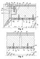
- FIG. 4 is a cross-sectional view of a front of the luminaire showing a way to mount the end cap to the housing with a hidden fastener, a hole for mounting the lightguide in the housing, and fasteners for mounting the circuit board to the housing;
- FIG. 5 is a cross-sectional view showing a central passageway between the channel and cavity for the circuit board and LEDs, which may receive wires connected to the circuit boards;
- FIGS. 6-9 are perspective, front, top and cross-sectional views of an end cap that can be connected to the housing of the edge lit luminaire of the first embodiment
- FIG. 10 is a perspective view of an edge lit luminaire of a second embodiment of this disclosure.
- FIG. 11 shows an exploded perspective view of the luminaire of the second embodiment
- FIG. 12 shows an end view of the luminaire of the second embodiment
- FIG. 13A is a cross-sectional view of the luminaire of the second embodiment showing a terminating end cap fitting into the housing;
- FIG. 13B is a top view of a reflector optic around the LEDs
- FIG. 14 is an end view of the housing of the edge lit luminaire of the second embodiment
- FIGS. 15 and 16 are cross-sectional views from an end of the luminaire of the second embodiment
- FIGS. 17-20 are perspective, front, top and cross-sectional views of an end cap that can be connected to the housing of the edge lit luminaire of the second embodiment;
- FIG. 21 shows a perspective view of an edge lit luminaire of a third embodiment having a different profile of the housing
- FIG. 22 shows fitting of an end cap into the housing of the edge lit luminaire of the third embodiment
- FIG. 23 shows perspective end view of the end cap of the luminaire of the third embodiment
- FIG. 24 is a cross-sectional view showing the cavity in the housing that receives the circuit board and LED and the light guide fastened in the housing of the luminaire of the third embodiment;
- FIG. 25 is a perspective view of two edge lit luminaires of the second embodiment connected with a connecting end cap shown in FIG. 26 ;
- FIG. 27 shows a cross-sectional view of the two luminaires and connecting end cap
- FIG. 28 is a perspective view of two luminaires of the second embodiment connected together with two connected terminating end caps shown in FIG. 29 ;
- FIG. 30 is a cross-sectional view of the two luminaires connected together with the connected two terminating end caps;
- FIG. 31 is an end view of the edge-lit luminaire of the first embodiment adapted to receive a film or plate around the lightguide;
- FIG. 32 is an enlarged cross-sectional view of the edge-lit luminaire of FIG. 31 ;
- FIGS. 33-36 are cross-sectional views of various clips holding a film or plate onto the various lightguides.
- FIG. 37 is a perspective view of the edge-lit luminaire of FIG. 31 having signage on the film or plate.
- the edge lit luminaire 10 includes a plurality of spaced apart light emitting diodes (LEDs) 12 , a first or outermost LED being labeled LED 12 a .
- the LEDs are mounted on a support structure located in the cavity, the support structure comprising, for example, a printed circuit board 14 .
- a housing 16 has an interior cavity 18 for receiving the LEDs 12 and the circuit board 14 .
- the housing 16 includes a heat sink (or is a heat sink) for directing heat away from the LEDs.
- the housing includes a plurality of fins 20 at an exterior surface thereof.
- End caps 22 secured to ends of the housing cover the cavity 18 at the ends of the housing.
- the end caps 22 include a plurality of fins 24 at an exterior surface thereof.
- a lightguide 26 is secured inside the housing 16 and has an edge 28 located in proximity to the LEDs 12 .
- At least one of a reflector and a lens 30 directs light from the LEDs to the edge of the lightguide.
- the lightguide includes a light extraction surface 32 enabling light to be transmitted from the lightguide.
- printed circuit board may refer to any of a rigid metal-clad printed circuit board, a rigid polymeric printed circuit board, a flexible metal-clad printed circuit film, and a flexible polymeric printed circuit film. Any of these PCB variations may be secured to the heat sink with any one or more of a threaded fastener, grease, pressure-sensitive adhesive (e.g. tape), or cured adhesive (e.g. epoxy).
- a threaded fastener e.g. tape
- cured adhesive e.g. epoxy
- the interface between the PCB and the heat sink i.e. the grease or adhesive, preferably has good thermal conductivity properties, low thermal contact resistance to effectively dissipate the heat in the LEDs to the heat sink, and high electrical contact resistance to electrically insulate the PCB from the heat sink.
- the circuit board is metal clad.
- the fins 24 on the end caps 22 are aligned with the fins 20 of the housing 16 .
- the housing 16 can have an hourglass shape as viewed from the ends of the housing ( FIGS. 1 and 3 ).
- the lightguide 26 has a planar shape. A shorter dimension of width of the lightguide extends between two spaced apart ends 34 , 36 of the lightguide and the housing is disposed, for example, at only one of the ends 34 , not at any other end of the lightguide. In particular, no housing or heat sink is disposed at the other end 36 of the lightguide or on its edges or side surface near that end.
- the housing includes a removable side section, for example, removable front plate 37 ( FIG. 3 ), on one or both sides permitting access to the cavity 18 .
- the housing includes opposing first and second surfaces 38 , 40 .
- the lightguide 26 is received in an opening 42 in the second surface.
- a channel 44 is disposed in the housing near the first surface 38 that can receive a head of a fastener for mounting the luminaire to a support surface.
- a slot 46 is disposed in the first surface 38 in communication with and a smaller size than the channel 44 for receiving a shank of the fastener.
- the first surface 38 includes an opening 48 ( FIGS. 4 and 6 ) that is larger than a head of the fastener, which communicates with the channel 44 .
- a passageway 50 communicates inside the housing 16 between the channel 44 and the cavity 18 ( FIGS. 4 and 5 ). The passageway receives electrical wires connected to the LEDs or to leads of the circuit boards.
- One of the housing and each of the end caps include a boss 52 and the other of the housing and each of the end caps (e.g., the housing 16 ) includes an opening 54 for receiving the boss.
- An optional fastener opening 56 extends from the first surface 38 , through the housing or the end caps and into the boss 52 ( FIG. 4 ).
- the fastener opening 56 can optionally be threaded in the boss (e.g., tapped portion 58 ).
- An optional hidden fastener 59 extending in each fastener opening 56 can secure the end caps to the housing.
- FIGS. 10-20 A second embodiment of the edge lit luminaire 10 is shown in FIGS. 10-20 ) where like parts are given the same reference numerals as the first embodiment throughout the several views. Some of the features shown only in the figures of the second embodiment are applicable to or interchangeable with those of the first embodiment (or third embodiment discussed below).
- the housing 62 and end caps 64 have a trapezoidal shape in an end profile.
- the housing may include a cutout 66 ( FIG. 11 ) for reducing the bulk of the housing.
- a device for attaching the luminaire to a ceiling includes a suspension wire 68 to which is secured a clutch mechanism 70 .
- a machine screw (e.g., M4) 72 is fastened to the clutch mechanism 66 and can include a shakeproof washer. The head of the screw 72 passes through the opening 48 into the channel 44 , while the shank of the fastener extends across the slot 46 . The clutch mechanism can then be slid in the channel 44 along the length of the housing until a desired attachment position is reached.
- FIGS. 21-24 A third embodiment is shown in FIGS. 21-24 .
- the luminaire 74 of this design has a different shape of the housing 76 and end caps 78 than in the first and second embodiments. Not all of the housing includes the fins as not all of the housing needs to function as a heat sink.
- a conduit 80 can be inserted into the housing 76 for containing the electrical wires between the LEDs (leads of the circuit boards) and power source and/or can be replaced by the supporting wire 68 and clutch mechanism 70 . If the hole in the end cap is threaded, a hollow stud may be inserted in place of conduit 80 . This allows the wire to go through the stud while the stud makes a mechanical connection to the end cap. Alternatively, the wire channel is in the end cap and the conduit 78 just accommodates a stud or cable gripper mechanism.
- FIGS. 22 and 24 shows the removable front plate 37 and a removable rear plate 82 with a tab feature 84 that mates with a recess 86 in the primary housing 76 .
- This tab may be tapered in a way that the rear plate (and optionally the front plate) may slide in only from the end of the heat sink. This reduces the number of fasteners required to fasten the rear (and front) plates to the heat sink. If a tight fit or interference fit is utilized in sliding the plates in to the heat sink, the end caps will secure the ends sufficiently such that no fasteners are needed to fasten the removable plates to the heat sink.
- the optical system of the luminaire comprises a light engine, the reflector and/or lens cups 30 , and the lightguide 26 .
- the light engine includes a plurality of the LEDs 12 linearly arranged on the metal-clad printed circuit board 14 (MCPCB).
- MCPCB metal-clad printed circuit board 14
- the number of LEDs and MCPCBs in the system is governed by the desired amount of light output and the distribution of light desired.
- One embodiment for a 4 foot long luminaire with an output of 1800 lumens/ft at total system power of under 100 W comprises 64 LEDs and 4 MCPCBs (16 LEDs/MCPCB).
- the LEDs are more specifically spaced about 17-19 mm apart.
- the first LED 12 a is located at a distance D 1 of between one half and one LED pitch length (i.e., 8.5-19 mm in this embodiment) from the edge of the luminaire housing (including the terminating end cap) as shown in FIGS. 4 and 13A .
- Two luminaires that are butted together with a connecting end cap between them could have a distance D 2 between the first or outermost LED 12 a on one luminaire and the first or outermost LED 12 a on the next luminaire ranging from one to two pitch lengths ( FIG. 27 ).
- Mounted on each MCPCB are 4 reflector cups 30 , for example.
- Each reflector cup is an elongated strip that surrounds four of the LEDs on each MCPCB.
- Fasteners 31 extend through the reflector/lens 30 and the PCB into the housing ( FIG. 13 ). It is desirable for the reflector/lens 30 to have as few pieces as possible. Ideally, each MCPCB would have one reflector strip that covers all LEDs on that MCPCB.
- the reflector cup has several functions, including directing light into the lightguide, protecting the LEDs from the lightguide during thermal expansion, and creating a flame-retardant interface between the MCPCB and the lightguide. It is desirable that the reflector cups be made from a moldable polymer with high reflectance and high flame-resistance.
- the size of the reflector or lens optic around each LED is governed in this embodiment by the width of the lightguide 26 , the size of the fasteners 31 , and the size of the LED 12 .
- the optic includes an oval or parabolic shaped cavity around the LED.
- the width of each optic OW ideally should not exceed the width of the lightguide so that light is not lost in the cavity 18 .
- the length of each optic OL should not exceed the LED pitch length so that adjacent optics do not overlap each other. More preferably, the length OL of the optic is less than the LED pitch length P by a distance equal to or slightly greater than the counterbore major diameter around the fastener 31 (fastener head clearance diameter CD).
- the length of the optic OL in this fashion ensures that the optic does not overlap with the head clearance hole of the fastener 31 .
- the depth of the optic OD should couple as closely to the LED as possible to avoid optical losses. However, sufficient mechanical tolerance must be given so the optic does not interfere with any part of the LED. This tolerance may be in the range of 0.05 mm to 0.5 mm but is not exclusive to that range. Due to the aforementioned size constraints placed on the optic OW, the shape of the optic, e.g. linear vs. parabolic surface curvature, is less sensitive to the overall luminaire optical efficiency, than in designs without these size constraints, as most of the light emitted from the LED is directly coupled into the lightguide and the shape of the optic surface does not significantly affect beam collimation.
- the lightguide is a 4 mm thick (in one aspect) acrylic sheet that receives light from the light engine at the 4 mm thick inlet edge. Light losses are minimized the closer this inlet edge is to the LEDs. Most of the light is trapped inside the lightguide 26 due to total internal reflection (TIR) until the light contacts a defect or light-extracting feature (shown generally by 32 ) that redirects the light out of the lightguide. It is preferred that no light-extracting features are located between surface 40 and the inlet edge of the lightguide. This prevents light loss in the region 42 that is covered by the housing and removable plate(s). The height of the region 42 , H, ( FIGS.
- the mixing zone 3 , 15 and 24 defines a mixing zone for light from the LEDs and is governed partly by the LED pitch length P ( FIG. 4 ).
- the LED pitch length P FIG. 4
- the pitch length P is constrained by the number and cost of LEDs required to provide the desired light level.
- the mixing zone height H is further constrained by the desired vertical dimension of the housing 16 .
- the ratio H/P is greater than about 0.8, so that if the pitch length P is 18 mm, the mixing zone height H is about 14.4 mm.
- the ideal ratio of H/P is between 0.8 and 1 to hide LED bright spots from the observer while maintaining a cost effective number of LEDs and housing size, but this range is not exclusive.
- Another feature of the invention is the option of adding signage to the lightguide 26 .
- Signage may be achieved in numerous ways.
- At least one of the density and size of the light-extracting features may be manipulated in a way that forms prominent letters, symbols, or graphics.
- a film may be applied to the lightguide 26 ; the film having letters, symbols, or graphics printed, engraved, or embossed on the film.
- the film is preferably transparent to maintain the transparency of the lightguide 26 when the luminaire is turned off.
- the film may have a pressure sensitive adhesive or thermoplastic adhesive on one side of it to adhere to the lightguide prior to installing the lightguide in the housing 16 .
- the film may have no adhesive and have the same perimeter and form as the lightguide (including corresponding through holes if applicable), such that the removable plates 37 and 82 compress the film against the lightguide 26 to hold the film in place in the region 42 .
- Static adhesion may be desired to keep the film on the lightguide but is not a necessity.
- yet another method of adding signage is to provide a clip 130 on the bottom edge of the lightguide 26 and include a small gap around both sides of the lightguide in the region 42 between the removable plates 37 , 82 and the lightguide 26 (or front removable plate 37 and the housing 16 if no rear removable plate is used) for sliding a plate or film 134 in close proximity to the lightguide and housing/housing plates.
- the plate or film 134 may be on one or both sides of the lightguide and in the example shown in FIG. 32 is on both sides and a top of the lightguide 26 .
- the clip shown in FIG. 33 is a press fit clip.
- the clip may comprise a shelf 136 for the plate or film 134 to rest on and a lip 138 to prevent the plate or film from sliding off the edge of the shelf.
- the gap in the region 42 allows the plate or film to slide into position while preventing the plate or film from falling out.
- the lightguide may include a groove 140 that can receive any of various shaped protrusions 142 so as to receive a tapered clip ( FIG. 34 ) a plane notch clip ( FIG. 35 ) or a round notch clip ( FIG. 36 ), for example.
- One or more end caps 22 may be removed temporarily to switch out the plate or film 134 if a new sign is to be displayed on either or both sides of the lightguide.
- the signage plate or film 134 may be replaced with a protective plate or film 134 , comprising a transparent substrate with no letters, symbols, or graphics 144 at all.
- the protective plate or film protects the lightguide from scratches, finger prints, and other undesirable defects both in handling the luminaire and in normal operation.
- the light engine of the luminaire generates a significant amount of heat that must be dissipated to the ambient.
- the heat sink 16 , 62 , 76 which the light engine is mounted on is designed to dissipate this heat efficiently without exceeding the size limitations of the luminaire and while maintaining an appearance that is aesthetically pleasing and low cost.
- the combination of superior thermal management, thin aesthetic profile, and cost-effectiveness is achieved by making the heat sink out of extruded aluminum that is painted white or silver or more specifically powder-coated white or silver with a high emissivity powder.
- the fins 20 provide increased surface area for better convection and radiation of thermal energy compared to a heat sink with no fin structure. Further, the top fin 86 on the front cover plate 37 makes a nearly invisible seam when the front plate is fastened to the bulk heat sink 16 ( FIGS. 10 and 12 ).
- One mode of manufacturing the heat sink 16 , 62 , 76 is by extruding aluminum, which is cost effective and can handle complex shapes.
- An alternative option is die-casting, which may be more expensive and more limiting in what shapes can be made. Both modes may require some post-processing to machine holes for threaded fasteners.
- the end caps 22 , 64 , 78 , 94 and 98 may be die-cast or extruded. Extrusion matches the style and finish of the end cap to the heat sink, but will require more post-processing than a die-cast end cap.
- the lightguide can be manufactured by injection molding for speed and cost effectiveness.
- a purpose of the end cap is to cover the open end of the extruded heat sink (cavity 18 in the housing) where the light engine is mounted, which ensures safety and provides for a more aesthetic finish.
- All end caps of this disclosure can have an identical fin structure to the housing/heat sink so that the end cap seam is not noticeable ( FIGS. 1 , 10 and 12 ).
- the end caps include several features that enhance the performance and finish of the luminaire. First, the top face of the end cap (or housing/heat sink) may have an oversized hole 48 so that suspension/mounting hardware can be inserted into channel 44 b on the end cap, the shank extending through slot 46 b of the end cap. The fastener is then received in the channel 44 and slot 46 at the top of the heat sink.
- the channel 44 , 44 b ( FIGS. 6 , 17 ) provides flexibility for the user to adjust the suspension/mounting hardware to a position anywhere along the length of the luminaire.
- a boss 52 protruding from the end cap. This boss 52 inserts into a corresponding opening 54 on the end face of the heat sink.
- the boss 52 features the tapped hole 58 (or plain hole for an interference fit with a pin or rivet) that aligns with the corresponding hole 56 through the vertical plane of the heat sink ( FIGS. 4 , 6 - 9 , 13 and 17 - 20 ).
- the end cap can be fastened through the top of the luminaire so that the “hidden” fastener 59 is not visible to an observer (e.g., when the luminaire is positioned vertically with the fastener on top or horizontally with the fastener against the wall). See FIG. 4 .
- the housing/heat sink may have a boss which mates with an opening in the end cap.
- the use of a boss 52 improves the alignment of the fins 24 on the end cap 22 , 64 , 78 with the fins 20 on the heat sink 16 , 62 , 76 , respectively, compared to two flat faces that are held together with a single screw. Additional fasteners could be used, but may not maintain the slim profile of the heat sink of the luminaire.
- the bottom of the end cap features a cavity 42 that accommodates the end of the lightguide ( FIG. 9 ).
- Each of a plurality of fasteners 88 inserts through an opening 89 in the front plate 37 or end cap (e.g., end cap 64 ), through a hole 90 in the lightguide 26 , and into a threaded opening 91 on the removable rear plate or rear portion of the end cap, or rear portion of the housing if no removable rear plate is used, to secure the lightguide in place ( FIGS. 3 , 10 and 11 ).
- the lightguide may have no through holes and instead set screws are inserted through the opening 89 in the removable front plate, for example, to compressively hold the lightguide inside the housing.
- the end face 92 of the end cap 22 , 64 , 78 provides an aesthetic finish and an ideal location for logos or text.
- end caps 22 Two varieties of end caps 22 may be used: a terminating end cap (e.g., the end cap 22 , 64 , 78 ) and a connecting end cap.
- the terminating end cap is typically used on a single heat sink luminaire in which no other heat sinks will be in the vicinity ( FIGS. 1 and 10 ). However, terminating end caps 94 can be joined together with a connecting member 96 ( FIGS. 28-30 ).
- a connecting end cap 98 can be used when two heat sinks of the luminaires will be placed end to end and joined via the end cap ( FIGS. 25-27 ).
- the LED spacing on a heat sink that is connected with other heat sinks can be close to uniform from one heat sink to another.
- two luminaires that are butted together with a connecting end cap or terminating end caps between them could have a distance D 2 between the first or outermost LED 12 a on one luminaire and the first or outermost LED 12 a on the next luminaire ranging from one to two pitch lengths ( FIGS. 27 and 30 ).
- one type of connecting end cap 98 is shared by two luminaires 60 .
- the connecting end cap 98 may include two bosses 52 fitted into two openings in the housing 54 .
- the connecting end cap 98 may include a recess 44 b and a slot 46 b that are aligned with the recess 44 and slot 46 of the housing. Openings 48 b can extend between the channel and boss for receiving fasteners that connect the connecting end cap 98 to each luminaire 60 .
- terminating end caps 94 connect two distinct end-to-end butted luminaires 60 of the second embodiment. Openings 48 b can extend between the channel and boss for receiving fasteners that connect the end cap 94 to each luminaire 60 .
- the connecting member 96 includes a plate 100 with openings 102 . Fasteners 104 pass through the openings 102 and nuts 106 are received in the recess portion 44 b , which connects the end caps 94 and both distinct luminaires 60 together.
- the connecting end caps may also be tapered or rounded such that two or more luminaires can be connected at an angle (i.e., non-linearly).
- the heat sink 16 , 62 , 76 comprises a bulk structure and a removable front plate 37 and/or removable back plate 108 ( FIG. 11 ). If the heat sink were a single piece, the assembler would have to slide the boards and reflector cups in from the edge, through a cavity that is, by design, only slightly larger than the light engine assembly. Further, attaching the light engine to the heat sink requires a number of fasteners 31 .
- a single heat sink only has an approximately 4 mm width of the opening 42 to accommodate the lightguide, which is the same space to fit the fastener and the tool used to secure the fastener to the heat sink ( FIGS. 3 , 15 and 16 ). This small space creates a cumbersome situation for properly securing the light engine.
- the removable front plate 37 is used to allow the assembler to attach the light engine boards with reflector cups to the surface on the bulk heat sink without major difficulty.
- the front plate 37 is fastened to the body of the heat sink 110 using fasteners 112 extending in openings 114 through the front plate into openings 116 in the housing body 110 ( FIGS. 3 and 11 ).
- a seam 77 between the front plate and bulk of the heat sink 70 is nearly invisible ( FIGS. 10 and 11 ).
- a removable rear plate 108 which closely mirrors the front plate 37 , may be used to allow even more access for mounting the light engine on the heat sink.
- the rear plate 108 may be fastened to the housing by fasteners 118 through openings 120 of the rear plate 108 aligned with openings in the body 110 of the housing ( FIG. 11 ).
- the drawbacks to this alternative embodiment is that it adds another part to the luminaire, it introduces additional thermal resistance in the heat sink, and it leaves less room for threads to fasten the front plate to the rear plate.
- the minimum thread engagement of a specific M3 fastener into the heat sink is about 3 mm. By keeping the bulk heat sink intact (i.e. eliminating the rear plate), the allowable thread engagement may be 6 mm or more, which is a suitable engagement. If no rear cover plate is needed, one side of the housing will have no visible fasteners, which is suitable for horizontal application.
- the removable front and/or rear plates have bosses or tabs (e.g., tabs 84 of back plate 82 ) that run the length of the plate instead of holes.
- the boss or tab mates with a corresponding cavity in the heat sink (e.g., cavity 86 ) so that the front and/or rear plates press or slide into place in the heat sink, which eliminates the need for fasteners.
- the tab 84 is a dovetail tab that slides into the heat sink cavity 86 from the end ( FIG. 24 ).
- the tab may consist of a series of pins that are press fit into the heat sink.
- the lightguide 26 is optical grade transparent material, e.g., acrylic, for superior optical properties.
- the thickness of the acrylic lightguide is governed by two parameters.
- the lightguide may be larger than the LED's inherent optic, which may be a 2.8 mm diameter dome or even larger.
- the dome covers the actual light-emitting chip on the LED and is there for optical purposes. Not all LEDs have domes like this, but it is understood that this dome is a component of the LED itself.
- a reflector and/or collimator (e.g., lens) 30 around each LED 12 is desirable to direct light into the lightguide in a specific manner. As lightguide thickness increases, more flexibility with the reflector/collimator is gained. Second, the maximum thickness of acrylic that is easily manufactured into a lightguide is 4 mm.
- the lightguide thickness is specifically 4 mm.
- the lightguide also has a plurality of through holes 90 near the LED coupling, which are used to accommodate fasteners 88 that secure the lightguide in place. These holes can be located half way between consecutive LEDs at a distance of about 5 mm or less from the light-coupling edge of the lightguide. This location reduces shadowing created by the through hole and fastener and minimizes the effect on the light that reaches the observer.
- An additional aesthetic feature of the lightguide is that it is transparent (main aspect) or translucent (alternative aspect) when the luminaire is turned off. Alternatively, the lightguide may have no through-holes and may be held in place with set screws.
- the lightguide 26 contains light-extracting features on a light extraction surface 32 that extract light that would otherwise be trapped inside the lightguide due to total internal reflection.
- the light extraction surface that might be used is shown, for example, in U.S. Pat. No. 5,613,751 in FIGS. 4 a - 4 d and in column 5, line 54 through column 6, line 20, which patent is incorporated herein by reference in its entirety.
- These light-extracting features may be of two varieties, for example: laser-etched pits or microlens structures. Laser-etched pits will scatter light in all directions while microlens structures will direct light in a preferential direction.
- Each of the light-extracting features may be arranged in a pattern of variable density, i.e.
- variable density and light-extracting feature shape control both luminance and illuminance uniformity, such that the lightguide may appear uniform to an observer and/or the area illuminated by the luminaire may achieve a desirable distribution and light level.
- the light-extracting features may be optimized for a luminaire oriented vertically (lightguide is perpendicular to the ground) or horizontally (lightguide is parallel to the ground) based on the desired distribution of light. For example, a vertical luminaire is appropriate if mounted above the aisle of a supermarket and light is desired to be on the shelves to either side of the luminaire.
- the light engine connects to a power supply unit (PSU).
- PSU power supply unit
- the PSU can be located remotely (i.e. inside a ceiling grid or otherwise out of primary sight) from the suspended or surface-mounted luminaire. Since the light engine is embedded in the heat sink, a passageway or channel 50 is present in the heat sink to permit the exit of the electrical wires extending between the PSU and the LEDs 12 (leads of the circuit board on which the LEDs are electrically connected). There are two locations that are appropriate for this channel 50 , one is in the center of the luminaire ( FIG. 5 ) and the other is in the end cap 22 ( FIG. 4 ). One way to design the electrical wire channel 50 is shown in FIGS.
- the luminaire in the vertical orientation can have a size, for example, of approximately 1200 mm long ⁇ 200 mm high or wide ⁇ 25 mm thick.
- the light source is any light source that is suitable for edge lit illumination including lasers.
- the shape, size and position of the fins can vary from what is shown in the drawings.
- the dimensions of the various components and features of the luminaire can vary.
- Other ways may be used for securing the end caps to the housing.
- the housing can have a variety of end profiles.
- the cavity and channel in the housing may have a different shape than what is shown in the drawings.
- a variety of different fasteners may be used to secure the housing to a support surface via the channel.
- the lightguide may have different shapes and employ various light extraction features so long as a reasonable illumination efficiency is achieved.
Abstract
Description
Claims (34)
Priority Applications (4)
| Application Number | Priority Date | Filing Date | Title |
|---|---|---|---|
| US13/363,881 US8764264B2 (en) | 2011-10-11 | 2012-02-01 | Edge-lit luminaire |
| CA2791358A CA2791358C (en) | 2011-10-11 | 2012-10-04 | Edge-lit luminaire |
| EP12187846.6A EP2581898B1 (en) | 2011-10-11 | 2012-10-09 | Edge-Lit Luminaire |
| AU2012238294A AU2012238294B2 (en) | 2011-10-11 | 2012-10-10 | Edge-lit luminaire |
Applications Claiming Priority (2)
| Application Number | Priority Date | Filing Date | Title |
|---|---|---|---|
| US201161545708P | 2011-10-11 | 2011-10-11 | |
| US13/363,881 US8764264B2 (en) | 2011-10-11 | 2012-02-01 | Edge-lit luminaire |
Publications (2)
| Publication Number | Publication Date |
|---|---|
| US20130088890A1 US20130088890A1 (en) | 2013-04-11 |
| US8764264B2 true US8764264B2 (en) | 2014-07-01 |
Family
ID=47519805
Family Applications (1)
| Application Number | Title | Priority Date | Filing Date |
|---|---|---|---|
| US13/363,881 Expired - Fee Related US8764264B2 (en) | 2011-10-11 | 2012-02-01 | Edge-lit luminaire |
Country Status (4)
| Country | Link |
|---|---|
| US (1) | US8764264B2 (en) |
| EP (1) | EP2581898B1 (en) |
| AU (1) | AU2012238294B2 (en) |
| CA (1) | CA2791358C (en) |
Cited By (4)
| Publication number | Priority date | Publication date | Assignee | Title |
|---|---|---|---|---|
| US20150160396A1 (en) * | 2013-03-15 | 2015-06-11 | Cree, Inc. | Luminaire Utilizing Waveguide |
| US20170148363A1 (en) * | 2015-11-25 | 2017-05-25 | Darrell Frycz | Illuminated Sign Device |
| US20190309931A1 (en) * | 2013-04-19 | 2019-10-10 | Quarkstar Llc | Illumination Devices with Adjustable Optical Elements |
| US11879620B2 (en) * | 2021-09-16 | 2024-01-23 | Ciena Corporation | Combined surface mount standoff and LED for space constrained applications |
Families Citing this family (27)
| Publication number | Priority date | Publication date | Assignee | Title |
|---|---|---|---|---|
| US20140029276A1 (en) * | 2012-07-30 | 2014-01-30 | Felipe Leon | Modular luminaire |
| US10422944B2 (en) | 2013-01-30 | 2019-09-24 | Ideal Industries Lighting Llc | Multi-stage optical waveguide for a luminaire |
| US9581750B2 (en) | 2013-03-15 | 2017-02-28 | Cree, Inc. | Outdoor and/or enclosed structure LED luminaire |
| US9920901B2 (en) | 2013-03-15 | 2018-03-20 | Cree, Inc. | LED lensing arrangement |
| US10379278B2 (en) | 2013-03-15 | 2019-08-13 | Ideal Industries Lighting Llc | Outdoor and/or enclosed structure LED luminaire outdoor and/or enclosed structure LED luminaire having outward illumination |
| US10502899B2 (en) | 2013-03-15 | 2019-12-10 | Ideal Industries Lighting Llc | Outdoor and/or enclosed structure LED luminaire |
| US9513424B2 (en) | 2013-03-15 | 2016-12-06 | Cree, Inc. | Optical components for luminaire |
| US9110209B2 (en) * | 2013-03-15 | 2015-08-18 | Cooper Technologies Company | Edgelit LED blade fixture |
| US10400984B2 (en) | 2013-03-15 | 2019-09-03 | Cree, Inc. | LED light fixture and unitary optic member therefor |
| WO2015089516A1 (en) * | 2013-12-09 | 2015-06-18 | Cree, Inc. | Optical waveguide bodies and luminaires utilizing same |
| US9632295B2 (en) | 2014-05-30 | 2017-04-25 | Cree, Inc. | Flood optic |
| US9335464B2 (en) | 2013-04-22 | 2016-05-10 | Cooper Technologies Company | Edge-lit light fixture |
| US10914539B2 (en) * | 2013-05-15 | 2021-02-09 | Osram Sylvania Inc. | Two piece aluminum heat sink |
| USD751648S1 (en) | 2013-08-21 | 2016-03-15 | Cooper Technologies Company | Light-emitting diode edge lighted airfield guidance sign |
| US9495892B2 (en) | 2013-08-21 | 2016-11-15 | Cooper Technologies Company | Light-emitting diode edge lighted airfield guidance sign |
| DE112015002581T5 (en) * | 2014-05-30 | 2017-04-06 | Cree, Inc. | LED LIGHT FOR USE OUTDOOR AND IN COMPLETED ROOMS |
| US9534382B2 (en) | 2014-07-16 | 2017-01-03 | Certainteed Canada, Inc. | Lighting assembly |
| CA2861363C (en) | 2014-08-29 | 2018-01-16 | Martin Daniel Gerkes | Strip light arrangement for t bar ceiling grid systems |
| USD796239S1 (en) * | 2015-01-29 | 2017-09-05 | Herbacin Cosmetic Gmbh | Rack |
| USD811137S1 (en) * | 2015-12-23 | 2018-02-27 | Lg Electronics Inc. | Shelf for display rack |
| EP3472512A1 (en) * | 2016-06-16 | 2019-04-24 | Signify Holding B.V. | A lighting system using a light guiding structure. |
| IT201600122416A1 (en) * | 2016-12-02 | 2018-06-02 | Eral S R L | EASY INSTALLATION AND FALSE CEILING INSTALLED WITH SUCH A LAMP STRUCTURE |
| WO2019061027A1 (en) * | 2017-09-26 | 2019-04-04 | 瑞仪光电(苏州)有限公司 | Lighting device |
| US10969535B2 (en) * | 2019-02-14 | 2021-04-06 | Ideal Industries Lighting Llc | Waveguide luminaire with side glare shield |
| WO2020232356A1 (en) * | 2019-05-16 | 2020-11-19 | Hubbell Incorporated | Edge lit luminaire |
| CN112576961A (en) * | 2019-09-27 | 2021-03-30 | 王定锋 | Assembled LED long lamp strip and manufacturing method |
| WO2021207784A1 (en) * | 2020-04-15 | 2021-10-21 | Sinext Pty Ltd | Signage assembly |
Citations (55)
| Publication number | Priority date | Publication date | Assignee | Title |
|---|---|---|---|---|
| US5613751A (en) | 1995-06-27 | 1997-03-25 | Lumitex, Inc. | Light emitting panel assemblies |
| US5636914A (en) * | 1992-04-24 | 1997-06-10 | Trusiani; Paul J. | Illuminated panel device |
| US5947578A (en) | 1995-10-24 | 1999-09-07 | Nu-Tech & Engineering, Inc. | Back lighting device |
| USD433520S (en) | 1999-09-01 | 2000-11-07 | Hubbell Incorporated | Housing for a luminaire |
| USD443095S1 (en) | 1999-10-26 | 2001-05-29 | M. Arthur Gensler, Jr. And Associates | Lighting fixture |
| US6305109B1 (en) | 1999-12-09 | 2001-10-23 | Chi-Huang Lee | Structure of signboard |
| US6705033B1 (en) * | 2002-05-13 | 2004-03-16 | Kenneth L. Greene | LED-illuminated outdoor sign |
| US7186014B2 (en) | 2003-08-08 | 2007-03-06 | Citizen Electronics Co., Ltd. | Double-faced lighting device |
| USD543305S1 (en) | 2006-07-12 | 2007-05-22 | Eiko Electric Products Corp. | Lamp for an aquarium |
| US20070247870A1 (en) | 2006-04-20 | 2007-10-25 | Mitsubishi Electric Corporation | Surface light source device |
| US7366393B2 (en) | 2006-01-13 | 2008-04-29 | Optical Research Associates | Light enhancing structures with three or more arrays of elongate features |
| US7384179B2 (en) | 2006-01-18 | 2008-06-10 | Mitsubishi Electric Corporation | Planar light source unit and image display apparatus using the same |
| US7452109B2 (en) | 2005-03-12 | 2008-11-18 | Samsung Electronics Co., Ltd. | Edge light type backlight unit having heat sink system |
| US20080284308A1 (en) | 2006-11-27 | 2008-11-20 | Siew It Pang | Low profile and high efficiency lighting device for backlighting applications |
| US20090147538A1 (en) | 2007-12-06 | 2009-06-11 | Tzu-Wei Wang | Light guide plate with laser process patterns on an incident plane and manufacturing method thereof |
| US7572045B2 (en) | 2002-03-28 | 2009-08-11 | Koninklijke Philips Electronics N.V. | Compact lighting system and display device |
| US20090244690A1 (en) | 2008-03-27 | 2009-10-01 | Rohm And Haas Electronic Materials Llc | Light guiding film having light extraction features |
| US7600908B2 (en) * | 2006-02-10 | 2009-10-13 | Hong Fu Jin Precision Industry (Shenzhen) Co., Ltd. | Light source module and backlight system using the same |
| US7618179B2 (en) | 2007-05-08 | 2009-11-17 | Citizen Electronics Co., Ltd. | Optical member, backlight unit and display apparatus |
| US20090316388A1 (en) | 2008-06-18 | 2009-12-24 | Hon Hai Precision Industry Co., Ltd. | Backlight module |
| USD607915S1 (en) | 2008-10-22 | 2010-01-12 | Fong Gary M | Photographic light diffuser |
| US20100014027A1 (en) | 2008-07-16 | 2010-01-21 | Jabil Circuit, Inc. | Led backlight having edge illuminator for flat panel lcd displays |
| US20100033955A1 (en) | 2008-08-08 | 2010-02-11 | Tsinghua University | Light guide plates and backlight module |
| US20100033989A1 (en) | 2008-08-08 | 2010-02-11 | Tun-Chien Teng | Light guide plate and edge-lighting type backlight module |
| US7661849B2 (en) | 2006-11-27 | 2010-02-16 | Ping Sun Patrick Lo | Illuminated apparatus |
| US20100046217A1 (en) | 2008-03-03 | 2010-02-25 | Ngai Peter Y Y | Optical system and method for managing brightness contrasts between high brightness light sources and surrounding surfaces |
| USD611633S1 (en) | 2009-05-18 | 2010-03-09 | Ottlite Technologies, Inc. | Book light |
| US7681347B1 (en) * | 2006-06-07 | 2010-03-23 | Imageworks Display And Marketing Group | Edge lit sign with illuminated image |
| US20100085773A1 (en) | 2009-01-02 | 2010-04-08 | Brian Edward Richardson | Optic system light guide with controlled output |
| US7695182B2 (en) | 2007-10-10 | 2010-04-13 | Fujifilm Corporation | Planar lighting device |
| US7706050B2 (en) | 2004-03-05 | 2010-04-27 | Qualcomm Mems Technologies, Inc. | Integrated modulator illumination |
| USD616137S1 (en) | 2008-12-08 | 2010-05-18 | Chien Luen Industries Co., Ltd., Inc. | Sign light device |
| US7740375B2 (en) | 2004-03-16 | 2010-06-22 | Koninklijke Philips Electronics N.V. | High brightness illumination device with incoherent solid state light source |
| US7766534B2 (en) | 2007-06-08 | 2010-08-03 | Fujifilm Corporation | Planar lighting device |
| US7766531B2 (en) | 2006-03-29 | 2010-08-03 | 3M Innovative Properties Company | Edge-lit optical display with fluted optical plate |
| US7766498B2 (en) | 2006-06-21 | 2010-08-03 | Qualcomm Mems Technologies, Inc. | Linear solid state illuminator |
| US20100201613A1 (en) | 2007-07-27 | 2010-08-12 | Sharp Kabushiki Kaisha | Illuminating device and display device provided with the same |
| US7780331B2 (en) | 2007-04-19 | 2010-08-24 | Stanley Electric Co., Ltd. | Surface illuminant equipment |
| US7780330B2 (en) | 2007-05-16 | 2010-08-24 | Rohm And Haas Electronics Materials Llc | Elongated illuminators configuration for LCD displays |
| US20100220497A1 (en) | 2009-01-14 | 2010-09-02 | Ngai Peter Y Y | Luminaire having floating luminous light source |
| USD624671S1 (en) | 2008-06-20 | 2010-09-28 | Glenda Greene | Window light display |
| USD626278S1 (en) | 2010-03-11 | 2010-10-26 | Eglo Leuchten Gmbh | Light fixture |
| US7824093B2 (en) | 2006-10-02 | 2010-11-02 | Samsung Electronics Co., Ltd. | Backlight assembly, liquid crystal display device having the same, and method of manufacturing thereof |
| US20100294001A1 (en) | 2002-10-04 | 2010-11-25 | Page David J | Method of making transparent light emitting members |
| US20100309409A1 (en) | 2009-06-03 | 2010-12-09 | Starkey Kurt R | Light emitting assemblies having defined regions of different brightness |
| US7855827B2 (en) | 2006-10-06 | 2010-12-21 | Qualcomm Mems Technologies, Inc. | Internal optical isolation structure for integrated front or back lighting |
| US20100328576A1 (en) | 2008-02-01 | 2010-12-30 | Kuraray Co., Ltd. | Surface light source element and image display apparatus including the same |
| US7864395B2 (en) | 2006-10-27 | 2011-01-04 | Qualcomm Mems Technologies, Inc. | Light guide including optical scattering elements and a method of manufacture |
| US7876489B2 (en) | 2006-06-05 | 2011-01-25 | Pixtronix, Inc. | Display apparatus with optical cavities |
| US7909496B2 (en) | 2006-02-01 | 2011-03-22 | Koninklijke Philips Electronics N.V. | Lighting system for creating an illuminated surface |
| US7909482B2 (en) | 2006-08-21 | 2011-03-22 | Innotec Corporation | Electrical device having boardless electrical component mounting arrangement |
| US7914197B2 (en) | 2005-12-27 | 2011-03-29 | Showa Denko K.K. | Light guide member, flat light source device, and display device |
| US7922381B2 (en) | 2003-06-26 | 2011-04-12 | Samsung Electronics Co., Ltd. | Two-way backlight assembly and two-way liquid crystal display apparatus having the same |
| US7931396B2 (en) | 2008-12-10 | 2011-04-26 | Sharp Kabushiki Kaisha | Backlight and display |
| KR20110095606A (en) | 2010-02-19 | 2011-08-25 | 네오세미테크 주식회사 | The vacuum line connector of coated bn |
Family Cites Families (3)
| Publication number | Priority date | Publication date | Assignee | Title |
|---|---|---|---|---|
| JP2007219431A (en) * | 2006-02-20 | 2007-08-30 | Meiko Kasei Kk | Indicating light |
| JP5198915B2 (en) * | 2008-03-31 | 2013-05-15 | トピー工業株式会社 | Double-sided light emitting display |
| JP2011095606A (en) * | 2009-10-30 | 2011-05-12 | Fukaden Corp | Andon information display device |
-
2012
- 2012-02-01 US US13/363,881 patent/US8764264B2/en not_active Expired - Fee Related
- 2012-10-04 CA CA2791358A patent/CA2791358C/en not_active Expired - Fee Related
- 2012-10-09 EP EP12187846.6A patent/EP2581898B1/en active Active
- 2012-10-10 AU AU2012238294A patent/AU2012238294B2/en not_active Ceased
Patent Citations (56)
| Publication number | Priority date | Publication date | Assignee | Title |
|---|---|---|---|---|
| US5636914A (en) * | 1992-04-24 | 1997-06-10 | Trusiani; Paul J. | Illuminated panel device |
| US5613751A (en) | 1995-06-27 | 1997-03-25 | Lumitex, Inc. | Light emitting panel assemblies |
| US5947578A (en) | 1995-10-24 | 1999-09-07 | Nu-Tech & Engineering, Inc. | Back lighting device |
| US6001210A (en) | 1995-10-24 | 1999-12-14 | Nu-Tech & Engineering, Inc. | Method of making a back lighting device |
| USD433520S (en) | 1999-09-01 | 2000-11-07 | Hubbell Incorporated | Housing for a luminaire |
| USD443095S1 (en) | 1999-10-26 | 2001-05-29 | M. Arthur Gensler, Jr. And Associates | Lighting fixture |
| US6305109B1 (en) | 1999-12-09 | 2001-10-23 | Chi-Huang Lee | Structure of signboard |
| US7572045B2 (en) | 2002-03-28 | 2009-08-11 | Koninklijke Philips Electronics N.V. | Compact lighting system and display device |
| US6705033B1 (en) * | 2002-05-13 | 2004-03-16 | Kenneth L. Greene | LED-illuminated outdoor sign |
| US20100294001A1 (en) | 2002-10-04 | 2010-11-25 | Page David J | Method of making transparent light emitting members |
| US7922381B2 (en) | 2003-06-26 | 2011-04-12 | Samsung Electronics Co., Ltd. | Two-way backlight assembly and two-way liquid crystal display apparatus having the same |
| US7186014B2 (en) | 2003-08-08 | 2007-03-06 | Citizen Electronics Co., Ltd. | Double-faced lighting device |
| US7706050B2 (en) | 2004-03-05 | 2010-04-27 | Qualcomm Mems Technologies, Inc. | Integrated modulator illumination |
| US7740375B2 (en) | 2004-03-16 | 2010-06-22 | Koninklijke Philips Electronics N.V. | High brightness illumination device with incoherent solid state light source |
| US7452109B2 (en) | 2005-03-12 | 2008-11-18 | Samsung Electronics Co., Ltd. | Edge light type backlight unit having heat sink system |
| US7914197B2 (en) | 2005-12-27 | 2011-03-29 | Showa Denko K.K. | Light guide member, flat light source device, and display device |
| US7366393B2 (en) | 2006-01-13 | 2008-04-29 | Optical Research Associates | Light enhancing structures with three or more arrays of elongate features |
| US7384179B2 (en) | 2006-01-18 | 2008-06-10 | Mitsubishi Electric Corporation | Planar light source unit and image display apparatus using the same |
| US7909496B2 (en) | 2006-02-01 | 2011-03-22 | Koninklijke Philips Electronics N.V. | Lighting system for creating an illuminated surface |
| US7600908B2 (en) * | 2006-02-10 | 2009-10-13 | Hong Fu Jin Precision Industry (Shenzhen) Co., Ltd. | Light source module and backlight system using the same |
| US7766531B2 (en) | 2006-03-29 | 2010-08-03 | 3M Innovative Properties Company | Edge-lit optical display with fluted optical plate |
| US20070247870A1 (en) | 2006-04-20 | 2007-10-25 | Mitsubishi Electric Corporation | Surface light source device |
| US7876489B2 (en) | 2006-06-05 | 2011-01-25 | Pixtronix, Inc. | Display apparatus with optical cavities |
| US7681347B1 (en) * | 2006-06-07 | 2010-03-23 | Imageworks Display And Marketing Group | Edge lit sign with illuminated image |
| US7766498B2 (en) | 2006-06-21 | 2010-08-03 | Qualcomm Mems Technologies, Inc. | Linear solid state illuminator |
| USD543305S1 (en) | 2006-07-12 | 2007-05-22 | Eiko Electric Products Corp. | Lamp for an aquarium |
| US7909482B2 (en) | 2006-08-21 | 2011-03-22 | Innotec Corporation | Electrical device having boardless electrical component mounting arrangement |
| US7824093B2 (en) | 2006-10-02 | 2010-11-02 | Samsung Electronics Co., Ltd. | Backlight assembly, liquid crystal display device having the same, and method of manufacturing thereof |
| US7855827B2 (en) | 2006-10-06 | 2010-12-21 | Qualcomm Mems Technologies, Inc. | Internal optical isolation structure for integrated front or back lighting |
| US7864395B2 (en) | 2006-10-27 | 2011-01-04 | Qualcomm Mems Technologies, Inc. | Light guide including optical scattering elements and a method of manufacture |
| US7661849B2 (en) | 2006-11-27 | 2010-02-16 | Ping Sun Patrick Lo | Illuminated apparatus |
| US20080284308A1 (en) | 2006-11-27 | 2008-11-20 | Siew It Pang | Low profile and high efficiency lighting device for backlighting applications |
| US7780331B2 (en) | 2007-04-19 | 2010-08-24 | Stanley Electric Co., Ltd. | Surface illuminant equipment |
| US7618179B2 (en) | 2007-05-08 | 2009-11-17 | Citizen Electronics Co., Ltd. | Optical member, backlight unit and display apparatus |
| US7780330B2 (en) | 2007-05-16 | 2010-08-24 | Rohm And Haas Electronics Materials Llc | Elongated illuminators configuration for LCD displays |
| US7766534B2 (en) | 2007-06-08 | 2010-08-03 | Fujifilm Corporation | Planar lighting device |
| US20100201613A1 (en) | 2007-07-27 | 2010-08-12 | Sharp Kabushiki Kaisha | Illuminating device and display device provided with the same |
| US7695182B2 (en) | 2007-10-10 | 2010-04-13 | Fujifilm Corporation | Planar lighting device |
| US20090147538A1 (en) | 2007-12-06 | 2009-06-11 | Tzu-Wei Wang | Light guide plate with laser process patterns on an incident plane and manufacturing method thereof |
| US20100328576A1 (en) | 2008-02-01 | 2010-12-30 | Kuraray Co., Ltd. | Surface light source element and image display apparatus including the same |
| US20100046217A1 (en) | 2008-03-03 | 2010-02-25 | Ngai Peter Y Y | Optical system and method for managing brightness contrasts between high brightness light sources and surrounding surfaces |
| US20090244690A1 (en) | 2008-03-27 | 2009-10-01 | Rohm And Haas Electronic Materials Llc | Light guiding film having light extraction features |
| US20090316388A1 (en) | 2008-06-18 | 2009-12-24 | Hon Hai Precision Industry Co., Ltd. | Backlight module |
| USD624671S1 (en) | 2008-06-20 | 2010-09-28 | Glenda Greene | Window light display |
| US20100014027A1 (en) | 2008-07-16 | 2010-01-21 | Jabil Circuit, Inc. | Led backlight having edge illuminator for flat panel lcd displays |
| US20100033989A1 (en) | 2008-08-08 | 2010-02-11 | Tun-Chien Teng | Light guide plate and edge-lighting type backlight module |
| US20100033955A1 (en) | 2008-08-08 | 2010-02-11 | Tsinghua University | Light guide plates and backlight module |
| USD607915S1 (en) | 2008-10-22 | 2010-01-12 | Fong Gary M | Photographic light diffuser |
| USD616137S1 (en) | 2008-12-08 | 2010-05-18 | Chien Luen Industries Co., Ltd., Inc. | Sign light device |
| US7931396B2 (en) | 2008-12-10 | 2011-04-26 | Sharp Kabushiki Kaisha | Backlight and display |
| US20100085773A1 (en) | 2009-01-02 | 2010-04-08 | Brian Edward Richardson | Optic system light guide with controlled output |
| US20100220497A1 (en) | 2009-01-14 | 2010-09-02 | Ngai Peter Y Y | Luminaire having floating luminous light source |
| USD611633S1 (en) | 2009-05-18 | 2010-03-09 | Ottlite Technologies, Inc. | Book light |
| US20100309409A1 (en) | 2009-06-03 | 2010-12-09 | Starkey Kurt R | Light emitting assemblies having defined regions of different brightness |
| KR20110095606A (en) | 2010-02-19 | 2011-08-25 | 네오세미테크 주식회사 | The vacuum line connector of coated bn |
| USD626278S1 (en) | 2010-03-11 | 2010-10-26 | Eglo Leuchten Gmbh | Light fixture |
Non-Patent Citations (3)
| Title |
|---|
| EP Search Report dated Nov. 7, 2013, from corresponding EP Patent Application No. 12187846.6. |
| PowerPoint slide presentation for LED edge-lit luminaire shown by GE Lighting at Light Fair in Philadelphia, PA in May 2011. |
| US 7,684,107, 8/2010, (withdrawn). |
Cited By (5)
| Publication number | Priority date | Publication date | Assignee | Title |
|---|---|---|---|---|
| US20150160396A1 (en) * | 2013-03-15 | 2015-06-11 | Cree, Inc. | Luminaire Utilizing Waveguide |
| US9952372B2 (en) * | 2013-03-15 | 2018-04-24 | Cree, Inc. | Luminaire utilizing waveguide |
| US20190309931A1 (en) * | 2013-04-19 | 2019-10-10 | Quarkstar Llc | Illumination Devices with Adjustable Optical Elements |
| US20170148363A1 (en) * | 2015-11-25 | 2017-05-25 | Darrell Frycz | Illuminated Sign Device |
| US11879620B2 (en) * | 2021-09-16 | 2024-01-23 | Ciena Corporation | Combined surface mount standoff and LED for space constrained applications |
Also Published As
| Publication number | Publication date |
|---|---|
| AU2012238294A1 (en) | 2013-05-02 |
| AU2012238294B2 (en) | 2015-11-19 |
| US20130088890A1 (en) | 2013-04-11 |
| EP2581898A3 (en) | 2013-12-11 |
| EP2581898B1 (en) | 2018-09-05 |
| CA2791358A1 (en) | 2013-04-11 |
| CA2791358C (en) | 2019-10-01 |
| EP2581898A2 (en) | 2013-04-17 |
Similar Documents
| Publication | Publication Date | Title |
|---|---|---|
| US8764264B2 (en) | Edge-lit luminaire | |
| EP3323318B1 (en) | Led strip light | |
| US10215911B2 (en) | Lighting assembly | |
| JP6345749B2 (en) | Lighting device | |
| US8690383B2 (en) | Collimating and controlling light produced by light emitting diodes | |
| US20100085748A1 (en) | Display case luminaires | |
| US8678616B2 (en) | LED luminaire for display cases | |
| US20100220497A1 (en) | Luminaire having floating luminous light source | |
| US8888316B2 (en) | Lenticular LED light source replacement for fluorescent in troffer | |
| US10156328B2 (en) | LED bar lighting and exhibition cabinet having same | |
| US7497600B2 (en) | Booster optic | |
| JP2011014317A (en) | Lighting body and lighting system | |
| JP2011014316A (en) | Lighting device | |
| KR20150117007A (en) | Lens optical system for luminous intensity distribution control of led groups, and led groups lighting included the same | |
| KR101150830B1 (en) | a frame for light-instrument with radiation of heat and LED lighting using frame | |
| KR101262810B1 (en) | Light guiding panel based thin and light flat-surface type led lighting device | |
| EP3382684A1 (en) | Light emitting diode assembly | |
| GB2552807A (en) | A planar LED light source module | |
| JP6375432B2 (en) | Lighting device |
Legal Events
| Date | Code | Title | Description |
|---|---|---|---|
| AS | Assignment |
Owner name: GE LIGHTING SOLUTIONS, LLC, OHIO Free format text: ASSIGNMENT OF ASSIGNORS INTEREST;ASSIGNORS:KNAPP, THOMAS ALEXANDER;DUREIKO, RICK;REEL/FRAME:027642/0739 Effective date: 20120118 |
|
| STCF | Information on status: patent grant |
Free format text: PATENTED CASE |
|
| CC | Certificate of correction | ||
| MAFP | Maintenance fee payment |
Free format text: PAYMENT OF MAINTENANCE FEE, 4TH YEAR, LARGE ENTITY (ORIGINAL EVENT CODE: M1551) Year of fee payment: 4 |
|
| AS | Assignment |
Owner name: CURRENT LIGHTING SOLUTIONS, LLC, OHIO Free format text: CHANGE OF NAME;ASSIGNOR:GE LIGHTING SOLUTIONS, LLC;REEL/FRAME:048830/0564 Effective date: 20190401 |
|
| AS | Assignment |
Owner name: ALLY BANK, AS COLLATERAL AGENT, NEW YORK Free format text: SECURITY AGREEMENT;ASSIGNORS:HUBBELL LIGHTING, INC.;LITECONTROL CORPORATION;CURRENT LIGHTING SOLUTIONS, LLC;AND OTHERS;REEL/FRAME:058982/0844 Effective date: 20220201 |
|
| AS | Assignment |
Owner name: ATLANTIC PARK STRATEGIC CAPITAL FUND, L.P., AS COLLATERAL AGENT, NEW YORK Free format text: SECURITY INTEREST;ASSIGNORS:HUBBELL LIGHTING, INC.;LITECONTROL CORPORATION;CURRENT LIGHTING SOLUTIONS, LLC;AND OTHERS;REEL/FRAME:059034/0469 Effective date: 20220201 |
|
| FEPP | Fee payment procedure |
Free format text: MAINTENANCE FEE REMINDER MAILED (ORIGINAL EVENT CODE: REM.); ENTITY STATUS OF PATENT OWNER: LARGE ENTITY |
|
| LAPS | Lapse for failure to pay maintenance fees |
Free format text: PATENT EXPIRED FOR FAILURE TO PAY MAINTENANCE FEES (ORIGINAL EVENT CODE: EXP.); ENTITY STATUS OF PATENT OWNER: LARGE ENTITY |
|
| STCH | Information on status: patent discontinuation |
Free format text: PATENT EXPIRED DUE TO NONPAYMENT OF MAINTENANCE FEES UNDER 37 CFR 1.362 |
|
| FP | Lapsed due to failure to pay maintenance fee |
Effective date: 20220701 |
|
| AS | Assignment |
Owner name: ALLY BANK, AS COLLATERAL AGENT, NEW YORK Free format text: CORRECTIVE ASSIGNMENT TO CORRECT THE PATENT NUMBER 10841994 TO PATENT NUMBER 11570872 PREVIOUSLY RECORDED ON REEL 058982 FRAME 0844. ASSIGNOR(S) HEREBY CONFIRMS THE SECURITY AGREEMENT;ASSIGNORS:HUBBELL LIGHTING, INC.;LITECONTROL CORPORATION;CURRENT LIGHTING SOLUTIONS, LLC;AND OTHERS;REEL/FRAME:066355/0455 Effective date: 20220201 |
|
| AS | Assignment |
Owner name: ATLANTIC PARK STRATEGIC CAPITAL FUND, L.P., AS COLLATERAL AGENT, NEW YORK Free format text: CORRECTIVE ASSIGNMENT TO CORRECT THE PATENT NUMBER PREVIOUSLY RECORDED AT REEL: 059034 FRAME: 0469. ASSIGNOR(S) HEREBY CONFIRMS THE SECURITY INTEREST;ASSIGNORS:HUBBELL LIGHTING, INC.;LITECONTROL CORPORATION;CURRENT LIGHTING SOLUTIONS, LLC;AND OTHERS;REEL/FRAME:066372/0590 Effective date: 20220201 |