US8767343B1 - Disk drive increasing integrator output range to complete seek operation - Google Patents
Disk drive increasing integrator output range to complete seek operation Download PDFInfo
- Publication number
- US8767343B1 US8767343B1 US13/454,752 US201213454752A US8767343B1 US 8767343 B1 US8767343 B1 US 8767343B1 US 201213454752 A US201213454752 A US 201213454752A US 8767343 B1 US8767343 B1 US 8767343B1
- Authority
- US
- United States
- Prior art keywords
- head
- recited
- disk drive
- integrating
- seek operation
- Prior art date
- Legal status (The legal status is an assumption and is not a legal conclusion. Google has not performed a legal analysis and makes no representation as to the accuracy of the status listed.)
- Active, expires
Links
- 238000000034 method Methods 0.000 claims description 12
- 230000004044 response Effects 0.000 claims description 3
- 230000000977 initiatory effect Effects 0.000 claims 1
- 238000010586 diagram Methods 0.000 description 12
- 230000007704 transition Effects 0.000 description 3
- 239000004065 semiconductor Substances 0.000 description 2
- 230000003044 adaptive effect Effects 0.000 description 1
- 238000013459 approach Methods 0.000 description 1
- 230000003111 delayed effect Effects 0.000 description 1
- 239000000314 lubricant Substances 0.000 description 1
- 230000000737 periodic effect Effects 0.000 description 1
- 230000035939 shock Effects 0.000 description 1
Images


Classifications
-
- G—PHYSICS
- G11—INFORMATION STORAGE
- G11B—INFORMATION STORAGE BASED ON RELATIVE MOVEMENT BETWEEN RECORD CARRIER AND TRANSDUCER
- G11B5/00—Recording by magnetisation or demagnetisation of a record carrier; Reproducing by magnetic means; Record carriers therefor
- G11B5/48—Disposition or mounting of heads or head supports relative to record carriers ; arrangements of heads, e.g. for scanning the record carrier to increase the relative speed
- G11B5/54—Disposition or mounting of heads or head supports relative to record carriers ; arrangements of heads, e.g. for scanning the record carrier to increase the relative speed with provision for moving the head into or out of its operative position or across tracks
- G11B5/55—Track change, selection or acquisition by displacement of the head
- G11B5/5521—Track change, selection or acquisition by displacement of the head across disk tracks
- G11B5/5526—Control therefor; circuits, track configurations or relative disposition of servo-information transducers and servo-information tracks for control thereof
- G11B5/553—Details
- G11B5/5547—"Seek" control and circuits therefor
Definitions
- Disk drives comprise a disk and a head connected to a distal end of an actuator arm which is rotated about a pivot by a voice coil motor (VCM) to position the head radially over the disk.
- VCM voice coil motor
- the disk comprises a plurality of radially spaced, concentric tracks for recording data sectors and servo sectors.
- the servo sectors comprise head positioning information (e.g., a track address) which is read by the head and processed by a servo control system to control the position and velocity of the actuator arm as it seeks from track to track.
- FIG. 1 shows a prior art disk format 2 as comprising a number of servo tracks 4 defined by servo sectors 6 0 - 6 N recorded around the circumference of each servo track.
- Each servo sector 6 i comprises a preamble 8 for storing a periodic pattern, which allows proper gain adjustment and timing synchronization of the read signal, and a sync mark 10 for storing a special pattern used to symbol-synchronize to a servo data field 12 .
- the servo data field 12 stores coarse head positioning information, such as a servo track address, used to position the head over a target data track during a seek operation.
- Each servo sector 4 further comprises groups of servo bursts 14 (A,B,C,D in the example shown), which are recorded with precise intervals and offsets relative to the track centerlines.
- the servo bursts 14 provide fine head position information used for centerline tracking while accessing a data track during write/read operations.
- Control circuitry is typically mounted on a printed circuit board (PCB) that is fastened to the base of the disk drive.
- the head is connected to the control circuitry through a flex circuit fastened on one side to the PCB and fastened on the other side to the side of the actuator arm.
- the flex circuit may induce a bias force on the actuator arm in addition to other bias forces, such as bearing friction in the actuator arm pivot bearing, and windage affecting the actuator arm as the disk rotates. If the bias forces on the actuator arm are not compensated correctly, it may cause the settle mode at the end of a seek to fail. This is illustrated in the prior art flow diagram of FIG. 2A which is understood with reference to FIG. 2B .
- the control circuitry seeks the head toward a target track (block 16 ).
- the control circuitry transitions into a settle mode (block 18 ) and attempts to settle the head onto the target track (block 20 ) as illustrated in FIG. 2B .
- the seek operation successfully settles the head onto the target track, the seek operation exits normally (block 22 ).
- various factors may prevent the successful completion of the normal seek operation. For example, if the bias forces applied to the actuator arm are not accurately compensated, the normal seek operation may be unable to overcome these bias forces resulting in a time-out (block 24 ) as illustrated in FIG. 2B .
- the control circuitry will typically report an error to the host (block 26 ).
- FIG. 1 shows a prior art disk format comprising a plurality of servo tracks defined by embedded servo sectors.
- FIG. 2A is a prior art flow diagram wherein the disk drive reports an error to the host when a seek operation times out before completing successfully.
- FIG. 2B illustrates a prior art example of the seek operation timing out before completing successfully.
- FIG. 3A is a disk drive according to an embodiment of the present invention comprising a disk, a head, and control circuitry including a servo control system operable to actuate the head over the disk.
- FIGS. 3B and 3C illustrate an embodiment of the present invention wherein during a seek operation an output range of an integrator may be increased if the seek operation does not complete successfully.
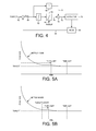
- FIG. 4 shows an embodiment of the present invention wherein the servo control system comprises a proportional/integral compensator.
- FIG. 5A illustrates an embodiment of the present invention wherein the output range of the integrator is increased when a time-limit is exceeded relative to a beginning of the settle mode.
- FIG. 5B illustrates an embodiment of the present invention wherein the output range of the integrator is increased when a time-limit is exceeded relative to when a state of the servo system exceeds a threshold.
- FIG. 6 is a flow diagram according to an embodiment of the present invention wherein increasing the output range of the integrator is delayed until a vibration subsides.
- FIG. 7 is a flow diagram according to an embodiment of the preset invention wherein when an increase in the output range of the integrator is needed to complete a seek operation, multiple long seeks are executed without accessing the disk to smoothen a bias force applied by the actuator arm pivot bearing.
- FIG. 3A shows a disk drive according to an embodiment of the present invention comprising a disk 28 comprising a plurality of data tracks 30 , a head 32 , and control circuitry 34 comprising a servo control system 36 ( FIG. 3B ) operable to actuate the head 32 over the disk 28 .
- the control circuitry 34 is operable to execute the flow diagram of FIG. 3C , wherein when an access command to access a target data track is received, a seek operation is initiated (block 38 ) to seek the head toward the target data track.
- the seek operation includes integrating a first state of the servo control system and limiting an output range of the integrating (block 40 ).
- the output range of the integrating is increased during the seek operation (block 46 ), for example, if an error occurs (block 44 ) during the seek operation.
- the disk 28 comprises embedded servo sectors 48 0 - 48 N that define the plurality of data tracks 30 .
- the control circuitry 34 processes a read signal 50 emanating from the head 32 to demodulate the servo sectors 48 0 - 48 N and generate a position error signal (PES) representing an error between the actual position of the head and a target position relative to a target track.
- PES position error signal
- the control circuitry 34 filters the PES using a suitable compensation filter to generate a control signal 52 applied to a voice coil motor (VCM) 54 which rotates an actuator arm 56 about a pivot in order to actuate the head 32 radially over the disk in a direction that reduces the PES.
- VCM voice coil motor
- the servo sectors 48 0 - 48 N may comprise any suitable position information, such as a track address for coarse positioning and servo bursts for fine positioning.
- the servo bursts may comprise any suitable servo burst pattern, such as an amplitude based servo burst pattern (A,B,C,D quadrature pattern) shown in FIG. 1 , or a phase based servo burst pattern (N,Q servo bursts).
- the first servo state 60 in FIG. 3B comprises a position error signal (PES) representing a difference between a target radial location of the head and a measured radial location of the head.
- PES position error signal
- An integrator 62 integrates the PES 60 , and the output range of the integrator 62 is limited 64 (both positive and negative amplitudes) based on a programmable range 66 .
- the integrator 62 forms part of a servo compensator, and in an embodiment shown in FIG. 4 , the integrator 62 is combined with a proportional term 68 to form a proportional/integral (PI) servo compensator.
- PI proportional/integral
- the output 70 of the proportional term 68 is added 72 to the output 74 of the integrator limiter 64 to generate a control signal 76 applied to an actuator 78 (e.g., VCM 54 and/or a microactuator not shown).
- the actuator 78 moves the head 32 in response to the control signal 76 , and the location of the head 80 is measured (e.g., by reading the servo sectors 48 0 - 48 N ).
- the measured location of the head 80 is subtracted from a target location 82 to generate the PES 60 .
- the servo control system may comprise any suitable algorithm, such as a proportional/integral/derivative (PID) compensator, as well as state space control, adaptive control, iterative learning, feed-forward compensation, etc.
- PID proportional/integral/derivative
- the integrator 62 and range limiter 64 may be implemented within any suitable component of the servo control algorithm (instead of or in addition to the integrator of a PI or PID controller).
- limiting the output range of the integrator helps prevent integrator windup which can lead to excessive overshoot during the seek operation.
- limiting the output range of the integrator may also prevent the servo control system from successfully completing a seek operation. For example, if a bias force applied to the actuator arm 56 is not properly compensated, it may prevent the seek operation from completing successfully. Accordingly, in one embodiment the output range of the integrating is increased during the seek operation in order to help ensure the seek operation completes successfully.
- FIG. 5A illustrates an example of the present invention wherein if the seek operation does not successfully complete when a time-limit expires, the output range of the integrating is increased. For example, if the bias force of the flex circuit is not properly compensated, the seek operation will essentially stall before successfully completing as shown in FIG. 5A . When the time-limit expires, the output range of the integrating is increased which causes the seek operation to complete successfully before reaching a time-out limit.
- the time-limit used to increase the output range of the integrating is set relative to a beginning of a settle mode near the end of the seek operation. That is, when the servo control system transitions into the settle mode, a timer is started. If the timer reaches the time-limit before the seek operation completes, the output range of the integrating is increased which will typically help the seek operation to finish before the timer reaches the time-out limit.
- FIG. 5B shows an alternative embodiment of the present invention wherein the time-limit is set relative to a state of the servo control system.
- the time-limit is set relative to when the PES falls below a predetermined threshold.
- the time-limit may be set relative to a different servo state, such as when the velocity of the head falls below a predetermined threshold.
- setting the time-limit relative to when a servo state reaches a threshold helps prevent the aforementioned integrator windup by delaying the increase in the integrator output range limit until the servo control system has settled sufficiently.
- FIG. 6 is a flow diagram according to an embodiment of the present invention wherein when an access command to access a target data track is received, a seek operation is initiated (block 84 ) to seek the head toward the target data track with the integrator disabled.
- the servo control system transitions into the settle mode (block 86 ) and enables the integrator (block 88 ).
- a servo state is integrated and the output range of the integrating is limited (block 90 ) during the settle mode. If the seek operation completes successfully (block 92 ), then the flow diagram exits normally.
- the control circuitry waits for the vibration to subside. If a time-out is reached (block 98 ) while waiting for the vibration to subside, then an error is reported (block 106 ). If the vibration subsides at block 96 , then the output range of the integrating is increased (block 100 ) and the settle mode continues.
- FIG. 7 is a flow diagram according to an embodiment of the present invention which is a variation on the flow diagram of FIG. 6 . If it becomes necessary to increase the output range of the integrator at block 100 , when the current seek operation terminates (successfully or unsuccessfully), a determination is made as to whether the disk drive is idle (e.g., no pending access commands). If the disk drive is not idle (block 108 ), then a flag is set (block 110 ).
- the control circuitry performs a plurality of long seeks each over at least one hundred data tracks without accessing the disk in order to smoothen a bias force and improve a likelihood subsequent seek operations will complete successfully within the time-limit.
- performing several long seeks may help reduce actuator ball and race burnishing as well as redistribute the lubricant within the pivot bearing of the actuator arm, and thereby smoothen the bias force applied to the actuator arm.
- control circuitry may be implemented within a read channel integrated circuit, or in a component separate from the read channel, such as a disk controller, or certain operations described above may be performed by a read channel and others by a disk controller.
- the read channel and disk controller are implemented as separate integrated circuits, and in an alternative embodiment they are fabricated into a single integrated circuit or system on a chip (SOC).
- the control circuitry may include a suitable preamp circuit implemented as a separate integrated circuit, integrated into the read channel or disk controller circuit, or integrated into an SOC.
- control circuitry comprises a microprocessor executing instructions, the instructions being operable to cause the microprocessor to perform the flow diagrams described herein.
- the instructions may be stored in any computer-readable medium. In one embodiment, they may be stored on a non-volatile semiconductor memory external to the microprocessor, or integrated with the microprocessor in a SOC. In another embodiment, the instructions are stored on the disk and read into a volatile semiconductor memory when the disk drive is powered on. In yet another embodiment, the control circuitry comprises suitable logic circuitry, such as state machine circuitry.
Abstract
Description
Claims (20)
Priority Applications (1)
| Application Number | Priority Date | Filing Date | Title |
|---|---|---|---|
| US13/454,752 US8767343B1 (en) | 2012-04-24 | 2012-04-24 | Disk drive increasing integrator output range to complete seek operation |
Applications Claiming Priority (1)
| Application Number | Priority Date | Filing Date | Title |
|---|---|---|---|
| US13/454,752 US8767343B1 (en) | 2012-04-24 | 2012-04-24 | Disk drive increasing integrator output range to complete seek operation |
Publications (1)
| Publication Number | Publication Date |
|---|---|
| US8767343B1 true US8767343B1 (en) | 2014-07-01 |
Family
ID=50982110
Family Applications (1)
| Application Number | Title | Priority Date | Filing Date |
|---|---|---|---|
| US13/454,752 Active 2032-09-15 US8767343B1 (en) | 2012-04-24 | 2012-04-24 | Disk drive increasing integrator output range to complete seek operation |
Country Status (1)
| Country | Link |
|---|---|
| US (1) | US8767343B1 (en) |
Cited By (76)
| Publication number | Priority date | Publication date | Assignee | Title |
|---|---|---|---|---|
| US8917474B1 (en) | 2011-08-08 | 2014-12-23 | Western Digital Technologies, Inc. | Disk drive calibrating a velocity profile prior to writing a spiral track |
| US8917475B1 (en) | 2013-12-20 | 2014-12-23 | Western Digital Technologies, Inc. | Disk drive generating a disk locked clock using radial dependent timing feed-forward compensation |
| US8922938B1 (en) | 2012-11-02 | 2014-12-30 | Western Digital Technologies, Inc. | Disk drive filtering disturbance signal and error signal for adaptive feed-forward compensation |
| US8922937B1 (en) | 2012-04-19 | 2014-12-30 | Western Digital Technologies, Inc. | Disk drive evaluating multiple vibration sensor outputs to enable write-protection |
| US8929022B1 (en) | 2012-12-19 | 2015-01-06 | Western Digital Technologies, Inc. | Disk drive detecting microactuator degradation by evaluating frequency component of servo signal |
| US8937784B1 (en) | 2012-08-01 | 2015-01-20 | Western Digital Technologies, Inc. | Disk drive employing feed-forward compensation and phase shift compensation during seek settling |
| US8941939B1 (en) | 2013-10-24 | 2015-01-27 | Western Digital Technologies, Inc. | Disk drive using VCM BEMF feed-forward compensation to write servo data to a disk |
| US8947819B1 (en) | 2012-08-28 | 2015-02-03 | Western Digital Technologies, Inc. | Disk drive implementing hysteresis for primary shock detector based on a more sensitive secondary shock detector |
| US8953278B1 (en) | 2011-11-16 | 2015-02-10 | Western Digital Technologies, Inc. | Disk drive selecting disturbance signal for feed-forward compensation |
| US8970979B1 (en) | 2013-12-18 | 2015-03-03 | Western Digital Technologies, Inc. | Disk drive determining frequency response of actuator near servo sample frequency |
| US8982501B1 (en) | 2014-09-22 | 2015-03-17 | Western Digital Technologies, Inc. | Data storage device compensating for repeatable disturbance when commutating a spindle motor |
| US9001454B1 (en) | 2013-04-12 | 2015-04-07 | Western Digital Technologies, Inc. | Disk drive adjusting phase of adaptive feed-forward controller when reconfiguring servo loop |
| US9007714B1 (en) | 2014-07-18 | 2015-04-14 | Western Digital Technologies Inc. | Data storage device comprising slew rate anti-windup compensation for microactuator |
| US9013825B1 (en) | 2014-03-24 | 2015-04-21 | Western Digital Technologies, Inc. | Electronic system with vibration management mechanism and method of operation thereof |
| US9026728B1 (en) | 2013-06-06 | 2015-05-05 | Western Digital Technologies, Inc. | Disk drive applying feed-forward compensation when writing consecutive data tracks |
| US9025269B1 (en) | 2014-01-02 | 2015-05-05 | Western Digital Technologies, Inc. | Disk drive compensating for cycle slip of disk locked clock when reading mini-wedge |
| US9047901B1 (en) | 2013-05-28 | 2015-06-02 | Western Digital Technologies, Inc. | Disk drive measuring spiral track error by measuring a slope of a spiral track across a disk radius |
| US9053712B1 (en) | 2014-05-07 | 2015-06-09 | Western Digital Technologies, Inc. | Data storage device reading servo sector while writing data sector |
| US9053727B1 (en) | 2014-06-02 | 2015-06-09 | Western Digital Technologies, Inc. | Disk drive opening spiral crossing window based on DC and AC spiral track error |
| US9058834B1 (en) | 2013-11-08 | 2015-06-16 | Western Digital Technologies, Inc. | Power architecture for low power modes in storage devices |
| US9064537B1 (en) | 2013-09-13 | 2015-06-23 | Western Digital Technologies, Inc. | Disk drive measuring radial offset between heads by detecting a difference between ramp contact |
| US9076472B1 (en) | 2014-08-21 | 2015-07-07 | Western Digital (Fremont), Llc | Apparatus enabling writing servo data when disk reaches target rotation speed |
| US9076471B1 (en) | 2013-07-31 | 2015-07-07 | Western Digital Technologies, Inc. | Fall detection scheme using FFS |
| US9076473B1 (en) | 2014-08-12 | 2015-07-07 | Western Digital Technologies, Inc. | Data storage device detecting fly height instability of head during load operation based on microactuator response |
| US9099147B1 (en) | 2014-09-22 | 2015-08-04 | Western Digital Technologies, Inc. | Data storage device commutating a spindle motor using closed-loop rotation phase alignment |
| US9111575B1 (en) | 2014-10-23 | 2015-08-18 | Western Digital Technologies, Inc. | Data storage device employing adaptive feed-forward control in timing loop to compensate for vibration |
| US9129630B1 (en) | 2014-12-16 | 2015-09-08 | Western Digital Technologies, Inc. | Data storage device employing full servo sectors on first disk surface and mini servo sectors on second disk surface |
| US9142225B1 (en) | 2014-03-21 | 2015-09-22 | Western Digital Technologies, Inc. | Electronic system with actuator control mechanism and method of operation thereof |
| US9141177B1 (en) | 2014-03-21 | 2015-09-22 | Western Digital Technologies, Inc. | Data storage device employing glitch compensation for power loss detection |
| US9142249B1 (en) | 2013-12-06 | 2015-09-22 | Western Digital Technologies, Inc. | Disk drive using timing loop control signal for vibration compensation in servo loop |
| US9142235B1 (en) | 2009-10-27 | 2015-09-22 | Western Digital Technologies, Inc. | Disk drive characterizing microactuator by injecting sinusoidal disturbance and evaluating feed-forward compensation values |
| US9147428B1 (en) | 2013-04-24 | 2015-09-29 | Western Digital Technologies, Inc. | Disk drive with improved spin-up control |
| US9153283B1 (en) | 2014-09-30 | 2015-10-06 | Western Digital Technologies, Inc. | Data storage device compensating for hysteretic response of microactuator |
| US9165583B1 (en) | 2014-10-29 | 2015-10-20 | Western Digital Technologies, Inc. | Data storage device adjusting seek profile based on seek length when ending track is near ramp |
| US9171568B1 (en) | 2014-06-25 | 2015-10-27 | Western Digital Technologies, Inc. | Data storage device periodically re-initializing spindle motor commutation sequence based on timing data |
| US9208808B1 (en) | 2014-04-22 | 2015-12-08 | Western Digital Technologies, Inc. | Electronic system with unload management mechanism and method of operation thereof |
| US9208815B1 (en) | 2014-10-09 | 2015-12-08 | Western Digital Technologies, Inc. | Data storage device dynamically reducing coast velocity during seek to reduce power consumption |
| US9208810B1 (en) | 2014-04-24 | 2015-12-08 | Western Digital Technologies, Inc. | Data storage device attenuating interference from first spiral track when reading second spiral track |
| US9214175B1 (en) | 2015-03-16 | 2015-12-15 | Western Digital Technologies, Inc. | Data storage device configuring a gain of a servo control system for actuating a head over a disk |
| US9230593B1 (en) | 2014-12-23 | 2016-01-05 | Western Digital Technologies, Inc. | Data storage device optimizing spindle motor power when transitioning into a power failure mode |
| US9230592B1 (en) | 2014-12-23 | 2016-01-05 | Western Digital Technologies, Inc. | Electronic system with a method of motor spindle bandwidth estimation and calibration thereof |
| US9245577B1 (en) | 2015-03-26 | 2016-01-26 | Western Digital Technologies, Inc. | Data storage device comprising spindle motor current sensing with supply voltage noise attenuation |
| US9245560B1 (en) | 2015-03-09 | 2016-01-26 | Western Digital Technologies, Inc. | Data storage device measuring reader/writer offset by reading spiral track and concentric servo sectors |
| US9245540B1 (en) | 2014-10-29 | 2016-01-26 | Western Digital Technologies, Inc. | Voice coil motor temperature sensing circuit to reduce catastrophic failure due to voice coil motor coil shorting to ground |
| US9251823B1 (en) | 2014-12-10 | 2016-02-02 | Western Digital Technologies, Inc. | Data storage device delaying seek operation to avoid thermal asperities |
| US9269386B1 (en) | 2014-01-29 | 2016-02-23 | Western Digital Technologies, Inc. | Data storage device on-line adapting disturbance observer filter |
| US9286927B1 (en) | 2014-12-16 | 2016-03-15 | Western Digital Technologies, Inc. | Data storage device demodulating servo burst by computing slope of intermediate integration points |
| US9286925B1 (en) | 2015-03-26 | 2016-03-15 | Western Digital Technologies, Inc. | Data storage device writing multiple burst correction values at the same radial location |
| US9343102B1 (en) | 2015-03-25 | 2016-05-17 | Western Digital Technologies, Inc. | Data storage device employing a phase offset to generate power from a spindle motor during a power failure |
| US9343094B1 (en) | 2015-03-26 | 2016-05-17 | Western Digital Technologies, Inc. | Data storage device filtering burst correction values before downsampling the burst correction values |
| US9349401B1 (en) | 2014-07-24 | 2016-05-24 | Western Digital Technologies, Inc. | Electronic system with media scan mechanism and method of operation thereof |
| US9355667B1 (en) | 2014-11-11 | 2016-05-31 | Western Digital Technologies, Inc. | Data storage device saving absolute position at each servo wedge for previous write operations |
| US9355676B1 (en) | 2015-03-25 | 2016-05-31 | Western Digital Technologies, Inc. | Data storage device controlling amplitude and phase of driving voltage to generate power from a spindle motor |
| US9390749B2 (en) | 2011-12-09 | 2016-07-12 | Western Digital Technologies, Inc. | Power failure management in disk drives |
| US9396751B1 (en) | 2015-06-26 | 2016-07-19 | Western Digital Technologies, Inc. | Data storage device compensating for fabrication tolerances when measuring spindle motor current |
| US9407015B1 (en) | 2014-12-29 | 2016-08-02 | Western Digital Technologies, Inc. | Automatic power disconnect device |
| US9418689B2 (en) | 2014-10-09 | 2016-08-16 | Western Digital Technologies, Inc. | Data storage device generating an operating seek time profile as a function of a base seek time profile |
| US9424871B1 (en) | 2012-09-13 | 2016-08-23 | Western Digital Technologies, Inc. | Disk drive correcting an error in a detected gray code |
| US9424868B1 (en) | 2015-05-12 | 2016-08-23 | Western Digital Technologies, Inc. | Data storage device employing spindle motor driving profile during seek to improve power performance |
| US9437237B1 (en) | 2015-02-20 | 2016-09-06 | Western Digital Technologies, Inc. | Method to detect power loss through data storage device spindle speed |
| US9437231B1 (en) | 2015-09-25 | 2016-09-06 | Western Digital Technologies, Inc. | Data storage device concurrently controlling and sensing a secondary actuator for actuating a head over a disk |
| US9454989B1 (en) | 2012-06-21 | 2016-09-27 | Western Digital Technologies, Inc. | Disk drive adjusting estimated servo state to compensate for transient when crossing a servo zone boundary |
| US9454212B1 (en) | 2014-12-08 | 2016-09-27 | Western Digital Technologies, Inc. | Wakeup detector |
| US9471072B1 (en) | 2013-11-14 | 2016-10-18 | Western Digital Technologies, Inc | Self-adaptive voltage scaling |
| US9484733B1 (en) | 2013-09-11 | 2016-11-01 | Western Digital Technologies, Inc. | Power control module for data storage device |
| US9542966B1 (en) | 2015-07-09 | 2017-01-10 | Western Digital Technologies, Inc. | Data storage devices and methods with frequency-shaped sliding mode control |
| US9564162B1 (en) | 2015-12-28 | 2017-02-07 | Western Digital Technologies, Inc. | Data storage device measuring resonant frequency of a shock sensor by applying differential excitation and measuring oscillation |
| US9564158B1 (en) * | 2016-05-12 | 2017-02-07 | Seagate Technology Llc | Methods and devices for adjusting actuator control signals |
| US9581978B1 (en) | 2014-12-17 | 2017-02-28 | Western Digital Technologies, Inc. | Electronic system with servo management mechanism and method of operation thereof |
| US9620160B1 (en) | 2015-12-28 | 2017-04-11 | Western Digital Technologies, Inc. | Data storage device measuring resonant frequency of a shock sensor by inserting the shock sensor into an oscillator circuit |
| US9823294B1 (en) | 2013-10-29 | 2017-11-21 | Western Digital Technologies, Inc. | Negative voltage testing methodology and tester |
| US9886285B2 (en) | 2015-03-31 | 2018-02-06 | Western Digital Technologies, Inc. | Communication interface initialization |
| US9899834B1 (en) | 2015-11-18 | 2018-02-20 | Western Digital Technologies, Inc. | Power control module using protection circuit for regulating backup voltage to power load during power fault |
| US9959204B1 (en) | 2015-03-09 | 2018-05-01 | Western Digital Technologies, Inc. | Tracking sequential ranges of non-ordered data |
| US20190317457A1 (en) * | 2018-04-13 | 2019-10-17 | Fanuc Corporation | Machine learning device, control device, and machine learning method |
| CN110376964A (en) * | 2018-04-13 | 2019-10-25 | 发那科株式会社 | Machine learning device, control device and machine learning method |
Citations (16)
| Publication number | Priority date | Publication date | Assignee | Title |
|---|---|---|---|---|
| US4189747A (en) * | 1967-09-15 | 1980-02-19 | Hughes Aircraft Company | Infrared tracking system |
| US4937803A (en) * | 1987-10-15 | 1990-06-26 | Kabushiki Kaisha Toshiba | Track acquisition apparatus and method with specified velocity pattern |
| US5056072A (en) * | 1987-08-20 | 1991-10-08 | Sony Corporation | Seek apparatus for optical disc drive |
| US5062023A (en) | 1990-04-13 | 1991-10-29 | Squire John S | Disk file servo loop with improved track settling |
| US5136441A (en) | 1989-04-20 | 1992-08-04 | Fujitsu Limited | Position control device for positioning magnetic head on selected track |
| US5602692A (en) * | 1994-10-07 | 1997-02-11 | International Business Machines Corporation | Sampled position error signal demodulation system for banded data disk drives |
| US5677809A (en) | 1990-09-18 | 1997-10-14 | Rodime Plc | Digital servo control system for use in disk drives, having state space observer including integral compensator |
| US6122135A (en) | 1997-12-19 | 2000-09-19 | Western Digital Corporation | Disk drive with voice coil motor rise time manager |
| US6166876A (en) | 1998-02-24 | 2000-12-26 | Seagate Technology, Inc. | Minimizing settling time in a disc drive servo system |
| US6476998B2 (en) | 1998-11-16 | 2002-11-05 | Maxtor Corporation | Enhanced settling control in hard disk drive |
| US20020196574A1 (en) | 2001-06-22 | 2002-12-26 | International Business Machines Corporation | System and method for reducing the accumulation of actuator bearing grease in hard disk drives |
| US20050002291A1 (en) | 2003-07-01 | 2005-01-06 | Kabushiki Kaisha Toshiba | Method and apparatus for head positioning control in a disk drive |
| US20060039079A1 (en) * | 2004-08-19 | 2006-02-23 | Hitachi Global Storage Technologies Netherlands B.V. | Magnetic disk apparatus with dual stage actuator |
| US20060092549A1 (en) | 2004-11-02 | 2006-05-04 | Hitachi Global Storage Technologies Netherlands B.V. | Magnetic disk drive and method for executing seek operation |
| US7253989B1 (en) | 2005-03-21 | 2007-08-07 | Western Digital Technologies, Inc. | Disk drive compensation of bias imparted by a flex circuit cable utilizing a dual bias curve estimation scheme |
| US7667922B1 (en) | 2004-01-08 | 2010-02-23 | Seagate Technology Llc | Estimation of bias force for data tracking in a disk drive |
-
2012
- 2012-04-24 US US13/454,752 patent/US8767343B1/en active Active
Patent Citations (17)
| Publication number | Priority date | Publication date | Assignee | Title |
|---|---|---|---|---|
| US4189747A (en) * | 1967-09-15 | 1980-02-19 | Hughes Aircraft Company | Infrared tracking system |
| US5056072A (en) * | 1987-08-20 | 1991-10-08 | Sony Corporation | Seek apparatus for optical disc drive |
| US4937803A (en) * | 1987-10-15 | 1990-06-26 | Kabushiki Kaisha Toshiba | Track acquisition apparatus and method with specified velocity pattern |
| US5136441A (en) | 1989-04-20 | 1992-08-04 | Fujitsu Limited | Position control device for positioning magnetic head on selected track |
| US5062023A (en) | 1990-04-13 | 1991-10-29 | Squire John S | Disk file servo loop with improved track settling |
| US5677809A (en) | 1990-09-18 | 1997-10-14 | Rodime Plc | Digital servo control system for use in disk drives, having state space observer including integral compensator |
| US5602692A (en) * | 1994-10-07 | 1997-02-11 | International Business Machines Corporation | Sampled position error signal demodulation system for banded data disk drives |
| US6122135A (en) | 1997-12-19 | 2000-09-19 | Western Digital Corporation | Disk drive with voice coil motor rise time manager |
| US6166876A (en) | 1998-02-24 | 2000-12-26 | Seagate Technology, Inc. | Minimizing settling time in a disc drive servo system |
| US6476998B2 (en) | 1998-11-16 | 2002-11-05 | Maxtor Corporation | Enhanced settling control in hard disk drive |
| US20020196574A1 (en) | 2001-06-22 | 2002-12-26 | International Business Machines Corporation | System and method for reducing the accumulation of actuator bearing grease in hard disk drives |
| US6754024B2 (en) | 2001-06-22 | 2004-06-22 | International Business Machines Corporation | System and method for reducing the accumulation of actuator bearing grease in hard disk drives |
| US20050002291A1 (en) | 2003-07-01 | 2005-01-06 | Kabushiki Kaisha Toshiba | Method and apparatus for head positioning control in a disk drive |
| US7667922B1 (en) | 2004-01-08 | 2010-02-23 | Seagate Technology Llc | Estimation of bias force for data tracking in a disk drive |
| US20060039079A1 (en) * | 2004-08-19 | 2006-02-23 | Hitachi Global Storage Technologies Netherlands B.V. | Magnetic disk apparatus with dual stage actuator |
| US20060092549A1 (en) | 2004-11-02 | 2006-05-04 | Hitachi Global Storage Technologies Netherlands B.V. | Magnetic disk drive and method for executing seek operation |
| US7253989B1 (en) | 2005-03-21 | 2007-08-07 | Western Digital Technologies, Inc. | Disk drive compensation of bias imparted by a flex circuit cable utilizing a dual bias curve estimation scheme |
Cited By (81)
| Publication number | Priority date | Publication date | Assignee | Title |
|---|---|---|---|---|
| US9142235B1 (en) | 2009-10-27 | 2015-09-22 | Western Digital Technologies, Inc. | Disk drive characterizing microactuator by injecting sinusoidal disturbance and evaluating feed-forward compensation values |
| US8917474B1 (en) | 2011-08-08 | 2014-12-23 | Western Digital Technologies, Inc. | Disk drive calibrating a velocity profile prior to writing a spiral track |
| US8953278B1 (en) | 2011-11-16 | 2015-02-10 | Western Digital Technologies, Inc. | Disk drive selecting disturbance signal for feed-forward compensation |
| US9390749B2 (en) | 2011-12-09 | 2016-07-12 | Western Digital Technologies, Inc. | Power failure management in disk drives |
| US8922937B1 (en) | 2012-04-19 | 2014-12-30 | Western Digital Technologies, Inc. | Disk drive evaluating multiple vibration sensor outputs to enable write-protection |
| US9454989B1 (en) | 2012-06-21 | 2016-09-27 | Western Digital Technologies, Inc. | Disk drive adjusting estimated servo state to compensate for transient when crossing a servo zone boundary |
| US8937784B1 (en) | 2012-08-01 | 2015-01-20 | Western Digital Technologies, Inc. | Disk drive employing feed-forward compensation and phase shift compensation during seek settling |
| US8947819B1 (en) | 2012-08-28 | 2015-02-03 | Western Digital Technologies, Inc. | Disk drive implementing hysteresis for primary shock detector based on a more sensitive secondary shock detector |
| US9424871B1 (en) | 2012-09-13 | 2016-08-23 | Western Digital Technologies, Inc. | Disk drive correcting an error in a detected gray code |
| US8922938B1 (en) | 2012-11-02 | 2014-12-30 | Western Digital Technologies, Inc. | Disk drive filtering disturbance signal and error signal for adaptive feed-forward compensation |
| US8929022B1 (en) | 2012-12-19 | 2015-01-06 | Western Digital Technologies, Inc. | Disk drive detecting microactuator degradation by evaluating frequency component of servo signal |
| US9001454B1 (en) | 2013-04-12 | 2015-04-07 | Western Digital Technologies, Inc. | Disk drive adjusting phase of adaptive feed-forward controller when reconfiguring servo loop |
| US9147428B1 (en) | 2013-04-24 | 2015-09-29 | Western Digital Technologies, Inc. | Disk drive with improved spin-up control |
| US9047901B1 (en) | 2013-05-28 | 2015-06-02 | Western Digital Technologies, Inc. | Disk drive measuring spiral track error by measuring a slope of a spiral track across a disk radius |
| US9026728B1 (en) | 2013-06-06 | 2015-05-05 | Western Digital Technologies, Inc. | Disk drive applying feed-forward compensation when writing consecutive data tracks |
| US9076471B1 (en) | 2013-07-31 | 2015-07-07 | Western Digital Technologies, Inc. | Fall detection scheme using FFS |
| US9484733B1 (en) | 2013-09-11 | 2016-11-01 | Western Digital Technologies, Inc. | Power control module for data storage device |
| US9064537B1 (en) | 2013-09-13 | 2015-06-23 | Western Digital Technologies, Inc. | Disk drive measuring radial offset between heads by detecting a difference between ramp contact |
| US8941939B1 (en) | 2013-10-24 | 2015-01-27 | Western Digital Technologies, Inc. | Disk drive using VCM BEMF feed-forward compensation to write servo data to a disk |
| US9823294B1 (en) | 2013-10-29 | 2017-11-21 | Western Digital Technologies, Inc. | Negative voltage testing methodology and tester |
| US9058834B1 (en) | 2013-11-08 | 2015-06-16 | Western Digital Technologies, Inc. | Power architecture for low power modes in storage devices |
| US9471072B1 (en) | 2013-11-14 | 2016-10-18 | Western Digital Technologies, Inc | Self-adaptive voltage scaling |
| US9142249B1 (en) | 2013-12-06 | 2015-09-22 | Western Digital Technologies, Inc. | Disk drive using timing loop control signal for vibration compensation in servo loop |
| US8970979B1 (en) | 2013-12-18 | 2015-03-03 | Western Digital Technologies, Inc. | Disk drive determining frequency response of actuator near servo sample frequency |
| US8917475B1 (en) | 2013-12-20 | 2014-12-23 | Western Digital Technologies, Inc. | Disk drive generating a disk locked clock using radial dependent timing feed-forward compensation |
| US9025269B1 (en) | 2014-01-02 | 2015-05-05 | Western Digital Technologies, Inc. | Disk drive compensating for cycle slip of disk locked clock when reading mini-wedge |
| US9269386B1 (en) | 2014-01-29 | 2016-02-23 | Western Digital Technologies, Inc. | Data storage device on-line adapting disturbance observer filter |
| US9142225B1 (en) | 2014-03-21 | 2015-09-22 | Western Digital Technologies, Inc. | Electronic system with actuator control mechanism and method of operation thereof |
| US9141177B1 (en) | 2014-03-21 | 2015-09-22 | Western Digital Technologies, Inc. | Data storage device employing glitch compensation for power loss detection |
| US9013825B1 (en) | 2014-03-24 | 2015-04-21 | Western Digital Technologies, Inc. | Electronic system with vibration management mechanism and method of operation thereof |
| US9208808B1 (en) | 2014-04-22 | 2015-12-08 | Western Digital Technologies, Inc. | Electronic system with unload management mechanism and method of operation thereof |
| US9208810B1 (en) | 2014-04-24 | 2015-12-08 | Western Digital Technologies, Inc. | Data storage device attenuating interference from first spiral track when reading second spiral track |
| US9053712B1 (en) | 2014-05-07 | 2015-06-09 | Western Digital Technologies, Inc. | Data storage device reading servo sector while writing data sector |
| US9053727B1 (en) | 2014-06-02 | 2015-06-09 | Western Digital Technologies, Inc. | Disk drive opening spiral crossing window based on DC and AC spiral track error |
| US9171568B1 (en) | 2014-06-25 | 2015-10-27 | Western Digital Technologies, Inc. | Data storage device periodically re-initializing spindle motor commutation sequence based on timing data |
| US9007714B1 (en) | 2014-07-18 | 2015-04-14 | Western Digital Technologies Inc. | Data storage device comprising slew rate anti-windup compensation for microactuator |
| US9349401B1 (en) | 2014-07-24 | 2016-05-24 | Western Digital Technologies, Inc. | Electronic system with media scan mechanism and method of operation thereof |
| US9076473B1 (en) | 2014-08-12 | 2015-07-07 | Western Digital Technologies, Inc. | Data storage device detecting fly height instability of head during load operation based on microactuator response |
| US9076472B1 (en) | 2014-08-21 | 2015-07-07 | Western Digital (Fremont), Llc | Apparatus enabling writing servo data when disk reaches target rotation speed |
| US9099147B1 (en) | 2014-09-22 | 2015-08-04 | Western Digital Technologies, Inc. | Data storage device commutating a spindle motor using closed-loop rotation phase alignment |
| US8982501B1 (en) | 2014-09-22 | 2015-03-17 | Western Digital Technologies, Inc. | Data storage device compensating for repeatable disturbance when commutating a spindle motor |
| US9153283B1 (en) | 2014-09-30 | 2015-10-06 | Western Digital Technologies, Inc. | Data storage device compensating for hysteretic response of microactuator |
| US9208815B1 (en) | 2014-10-09 | 2015-12-08 | Western Digital Technologies, Inc. | Data storage device dynamically reducing coast velocity during seek to reduce power consumption |
| US9418689B2 (en) | 2014-10-09 | 2016-08-16 | Western Digital Technologies, Inc. | Data storage device generating an operating seek time profile as a function of a base seek time profile |
| US9111575B1 (en) | 2014-10-23 | 2015-08-18 | Western Digital Technologies, Inc. | Data storage device employing adaptive feed-forward control in timing loop to compensate for vibration |
| US9245540B1 (en) | 2014-10-29 | 2016-01-26 | Western Digital Technologies, Inc. | Voice coil motor temperature sensing circuit to reduce catastrophic failure due to voice coil motor coil shorting to ground |
| US9165583B1 (en) | 2014-10-29 | 2015-10-20 | Western Digital Technologies, Inc. | Data storage device adjusting seek profile based on seek length when ending track is near ramp |
| US9355667B1 (en) | 2014-11-11 | 2016-05-31 | Western Digital Technologies, Inc. | Data storage device saving absolute position at each servo wedge for previous write operations |
| US9454212B1 (en) | 2014-12-08 | 2016-09-27 | Western Digital Technologies, Inc. | Wakeup detector |
| US9251823B1 (en) | 2014-12-10 | 2016-02-02 | Western Digital Technologies, Inc. | Data storage device delaying seek operation to avoid thermal asperities |
| US9286927B1 (en) | 2014-12-16 | 2016-03-15 | Western Digital Technologies, Inc. | Data storage device demodulating servo burst by computing slope of intermediate integration points |
| US9129630B1 (en) | 2014-12-16 | 2015-09-08 | Western Digital Technologies, Inc. | Data storage device employing full servo sectors on first disk surface and mini servo sectors on second disk surface |
| US9581978B1 (en) | 2014-12-17 | 2017-02-28 | Western Digital Technologies, Inc. | Electronic system with servo management mechanism and method of operation thereof |
| US9230592B1 (en) | 2014-12-23 | 2016-01-05 | Western Digital Technologies, Inc. | Electronic system with a method of motor spindle bandwidth estimation and calibration thereof |
| US9230593B1 (en) | 2014-12-23 | 2016-01-05 | Western Digital Technologies, Inc. | Data storage device optimizing spindle motor power when transitioning into a power failure mode |
| US9761266B2 (en) | 2014-12-23 | 2017-09-12 | Western Digital Technologies, Inc. | Data storage device optimizing spindle motor power when transitioning into a power failure mode |
| US9407015B1 (en) | 2014-12-29 | 2016-08-02 | Western Digital Technologies, Inc. | Automatic power disconnect device |
| US9437237B1 (en) | 2015-02-20 | 2016-09-06 | Western Digital Technologies, Inc. | Method to detect power loss through data storage device spindle speed |
| US9245560B1 (en) | 2015-03-09 | 2016-01-26 | Western Digital Technologies, Inc. | Data storage device measuring reader/writer offset by reading spiral track and concentric servo sectors |
| US9959204B1 (en) | 2015-03-09 | 2018-05-01 | Western Digital Technologies, Inc. | Tracking sequential ranges of non-ordered data |
| US9214175B1 (en) | 2015-03-16 | 2015-12-15 | Western Digital Technologies, Inc. | Data storage device configuring a gain of a servo control system for actuating a head over a disk |
| US9355676B1 (en) | 2015-03-25 | 2016-05-31 | Western Digital Technologies, Inc. | Data storage device controlling amplitude and phase of driving voltage to generate power from a spindle motor |
| US9343102B1 (en) | 2015-03-25 | 2016-05-17 | Western Digital Technologies, Inc. | Data storage device employing a phase offset to generate power from a spindle motor during a power failure |
| US9286925B1 (en) | 2015-03-26 | 2016-03-15 | Western Digital Technologies, Inc. | Data storage device writing multiple burst correction values at the same radial location |
| US9245577B1 (en) | 2015-03-26 | 2016-01-26 | Western Digital Technologies, Inc. | Data storage device comprising spindle motor current sensing with supply voltage noise attenuation |
| US9343094B1 (en) | 2015-03-26 | 2016-05-17 | Western Digital Technologies, Inc. | Data storage device filtering burst correction values before downsampling the burst correction values |
| US9886285B2 (en) | 2015-03-31 | 2018-02-06 | Western Digital Technologies, Inc. | Communication interface initialization |
| US9424868B1 (en) | 2015-05-12 | 2016-08-23 | Western Digital Technologies, Inc. | Data storage device employing spindle motor driving profile during seek to improve power performance |
| US9396751B1 (en) | 2015-06-26 | 2016-07-19 | Western Digital Technologies, Inc. | Data storage device compensating for fabrication tolerances when measuring spindle motor current |
| US9542966B1 (en) | 2015-07-09 | 2017-01-10 | Western Digital Technologies, Inc. | Data storage devices and methods with frequency-shaped sliding mode control |
| US9437231B1 (en) | 2015-09-25 | 2016-09-06 | Western Digital Technologies, Inc. | Data storage device concurrently controlling and sensing a secondary actuator for actuating a head over a disk |
| US9899834B1 (en) | 2015-11-18 | 2018-02-20 | Western Digital Technologies, Inc. | Power control module using protection circuit for regulating backup voltage to power load during power fault |
| US10127952B2 (en) | 2015-11-18 | 2018-11-13 | Western Digital Technologies, Inc. | Power control module using protection circuit for regulating backup voltage to power load during power fault |
| US9620160B1 (en) | 2015-12-28 | 2017-04-11 | Western Digital Technologies, Inc. | Data storage device measuring resonant frequency of a shock sensor by inserting the shock sensor into an oscillator circuit |
| US9564162B1 (en) | 2015-12-28 | 2017-02-07 | Western Digital Technologies, Inc. | Data storage device measuring resonant frequency of a shock sensor by applying differential excitation and measuring oscillation |
| US9564158B1 (en) * | 2016-05-12 | 2017-02-07 | Seagate Technology Llc | Methods and devices for adjusting actuator control signals |
| US20190317457A1 (en) * | 2018-04-13 | 2019-10-17 | Fanuc Corporation | Machine learning device, control device, and machine learning method |
| CN110376964A (en) * | 2018-04-13 | 2019-10-25 | 发那科株式会社 | Machine learning device, control device and machine learning method |
| US10877442B2 (en) * | 2018-04-13 | 2020-12-29 | Fanuc Corporation | Machine learning device, control device, and machine learning method |
| US10901396B2 (en) * | 2018-04-13 | 2021-01-26 | Fanuc Corporation | Machine learning device, control device, and machine learning method |
| CN110376964B (en) * | 2018-04-13 | 2021-11-19 | 发那科株式会社 | Machine learning device, control device, and machine learning method |
Similar Documents
| Publication | Publication Date | Title |
|---|---|---|
| US8767343B1 (en) | Disk drive increasing integrator output range to complete seek operation | |
| US8553351B1 (en) | Disk drive correcting track ID in response to an estimated radial location and a burst PES | |
| US8072703B1 (en) | Disk drive detecting when head is parked on ramp | |
| US8786976B1 (en) | Disk drive detecting when head is on ramp | |
| US7760458B1 (en) | Disk drive adjusting head bias during servo synchronization to compensate for over/under sensitivity | |
| US8842385B1 (en) | Disk drive decreasing an adapting delay based on speed that a settle parameter adapts | |
| US8699173B1 (en) | Disk drive detecting touchdown event by evaluating frequency response of a touchdown metric | |
| US8090902B1 (en) | Disk drive adjusting command execution in response to control circuitry die temperature | |
| US7304819B1 (en) | Method for writing repeatable runout correction values to a magnetic disk of a disk drive | |
| US8780479B1 (en) | Disk drive executing jerk seeks to rotate pivot ball bearings relative to races | |
| US7839600B1 (en) | Disk drive employing data-based basis function expansion for tuning seek servo loop | |
| US8537486B2 (en) | Disk drive writing spiral tracks on a slave surface using repeatable runout compensation for a master surface | |
| US9940958B1 (en) | Data storage device employing delayed braking to unload multiple voice coil motors | |
| US9053724B1 (en) | Disk drive actuating first head microactuator while sensing signal from second head microactuator | |
| US10878844B1 (en) | Data storage device controlling head fly height based on temperature | |
| US9165583B1 (en) | Data storage device adjusting seek profile based on seek length when ending track is near ramp | |
| US10347278B1 (en) | Data storage device configuring a write inhibit shock threshold for multiple actuators | |
| US7079337B2 (en) | Bi staple flying height detection by BEMF control profile and data integrity problem protection | |
| US10714133B1 (en) | Data storage device capable of overriding a servo command to avoid an overcurrent condition | |
| US6995940B2 (en) | Systems for WORF improvement in conditional servowriting | |
| US8913338B1 (en) | Disk drive reducing write unsafe threshold when detecting an unrecoverable servo compensation value | |
| US9437242B1 (en) | Data storage device employing different frequency preambles in adjacent data tracks | |
| US10109308B1 (en) | Data storage device using programmable deglitch window to detect saturation of VCM current control | |
| US20230091001A1 (en) | Magnetic disk device | |
| US8861126B1 (en) | Disk drive detecting when head is on ramp |
Legal Events
| Date | Code | Title | Description |
|---|---|---|---|
| AS | Assignment |
Owner name: WESTERN DIGITAL TECHNOLOGIES, INC., CALIFORNIA Free format text: ASSIGNMENT OF ASSIGNORS INTEREST;ASSIGNORS:HELMICK, DANIEL L.;BRUNNETT, DONALD;NARAYANA, ASWARTHA;AND OTHERS;SIGNING DATES FROM 20120418 TO 20120423;REEL/FRAME:028099/0148 |
|
| STCF | Information on status: patent grant |
Free format text: PATENTED CASE |
|
| AS | Assignment |
Owner name: JPMORGAN CHASE BANK, N.A., AS COLLATERAL AGENT, ILLINOIS Free format text: SECURITY AGREEMENT;ASSIGNOR:WESTERN DIGITAL TECHNOLOGIES, INC.;REEL/FRAME:038722/0229 Effective date: 20160512 Owner name: U.S. BANK NATIONAL ASSOCIATION, AS COLLATERAL AGENT, CALIFORNIA Free format text: SECURITY AGREEMENT;ASSIGNOR:WESTERN DIGITAL TECHNOLOGIES, INC.;REEL/FRAME:038744/0281 Effective date: 20160512 Owner name: JPMORGAN CHASE BANK, N.A., AS COLLATERAL AGENT, ILLINOIS Free format text: SECURITY AGREEMENT;ASSIGNOR:WESTERN DIGITAL TECHNOLOGIES, INC.;REEL/FRAME:038744/0481 Effective date: 20160512 Owner name: JPMORGAN CHASE BANK, N.A., AS COLLATERAL AGENT, IL Free format text: SECURITY AGREEMENT;ASSIGNOR:WESTERN DIGITAL TECHNOLOGIES, INC.;REEL/FRAME:038722/0229 Effective date: 20160512 Owner name: U.S. BANK NATIONAL ASSOCIATION, AS COLLATERAL AGEN Free format text: SECURITY AGREEMENT;ASSIGNOR:WESTERN DIGITAL TECHNOLOGIES, INC.;REEL/FRAME:038744/0281 Effective date: 20160512 Owner name: JPMORGAN CHASE BANK, N.A., AS COLLATERAL AGENT, IL Free format text: SECURITY AGREEMENT;ASSIGNOR:WESTERN DIGITAL TECHNOLOGIES, INC.;REEL/FRAME:038744/0481 Effective date: 20160512 |
|
| MAFP | Maintenance fee payment |
Free format text: PAYMENT OF MAINTENANCE FEE, 4TH YEAR, LARGE ENTITY (ORIGINAL EVENT CODE: M1551) Year of fee payment: 4 |
|
| AS | Assignment |
Owner name: WESTERN DIGITAL TECHNOLOGIES, INC., CALIFORNIA Free format text: RELEASE BY SECURED PARTY;ASSIGNOR:U.S. BANK NATIONAL ASSOCIATION, AS COLLATERAL AGENT;REEL/FRAME:045501/0714 Effective date: 20180227 |
|
| MAFP | Maintenance fee payment |
Free format text: PAYMENT OF MAINTENANCE FEE, 8TH YEAR, LARGE ENTITY (ORIGINAL EVENT CODE: M1552); ENTITY STATUS OF PATENT OWNER: LARGE ENTITY Year of fee payment: 8 |
|
| AS | Assignment |
Owner name: WESTERN DIGITAL TECHNOLOGIES, INC., CALIFORNIA Free format text: RELEASE OF SECURITY INTEREST AT REEL 038744 FRAME 0481;ASSIGNOR:JPMORGAN CHASE BANK, N.A.;REEL/FRAME:058982/0556 Effective date: 20220203 |
|
| AS | Assignment |
Owner name: JPMORGAN CHASE BANK, N.A., ILLINOIS Free format text: PATENT COLLATERAL AGREEMENT - A&R LOAN AGREEMENT;ASSIGNOR:WESTERN DIGITAL TECHNOLOGIES, INC.;REEL/FRAME:064715/0001 Effective date: 20230818 |