US8770927B2 - Abrasive cutter formed by thermal spray and post treatment - Google Patents
Abrasive cutter formed by thermal spray and post treatment Download PDFInfo
- Publication number
- US8770927B2 US8770927B2 US12/911,004 US91100410A US8770927B2 US 8770927 B2 US8770927 B2 US 8770927B2 US 91100410 A US91100410 A US 91100410A US 8770927 B2 US8770927 B2 US 8770927B2
- Authority
- US
- United States
- Prior art keywords
- airfoil
- abrasive layer
- seal member
- engine
- seal
- Prior art date
- Legal status (The legal status is an assumption and is not a legal conclusion. Google has not performed a legal analysis and makes no representation as to the accuracy of the status listed.)
- Active, expires
Links
Images


Classifications
-
- F—MECHANICAL ENGINEERING; LIGHTING; HEATING; WEAPONS; BLASTING
- F16—ENGINEERING ELEMENTS AND UNITS; GENERAL MEASURES FOR PRODUCING AND MAINTAINING EFFECTIVE FUNCTIONING OF MACHINES OR INSTALLATIONS; THERMAL INSULATION IN GENERAL
- F16J—PISTONS; CYLINDERS; SEALINGS
- F16J15/00—Sealings
- F16J15/44—Free-space packings
- F16J15/445—Free-space packings with means for adjusting the clearance
-
- F—MECHANICAL ENGINEERING; LIGHTING; HEATING; WEAPONS; BLASTING
- F01—MACHINES OR ENGINES IN GENERAL; ENGINE PLANTS IN GENERAL; STEAM ENGINES
- F01D—NON-POSITIVE DISPLACEMENT MACHINES OR ENGINES, e.g. STEAM TURBINES
- F01D11/00—Preventing or minimising internal leakage of working-fluid, e.g. between stages
- F01D11/08—Preventing or minimising internal leakage of working-fluid, e.g. between stages for sealing space between rotor blade tips and stator
- F01D11/12—Preventing or minimising internal leakage of working-fluid, e.g. between stages for sealing space between rotor blade tips and stator using a rubstrip, e.g. erodible. deformable or resiliently-biased part
- F01D11/122—Preventing or minimising internal leakage of working-fluid, e.g. between stages for sealing space between rotor blade tips and stator using a rubstrip, e.g. erodible. deformable or resiliently-biased part with erodable or abradable material
-
- F—MECHANICAL ENGINEERING; LIGHTING; HEATING; WEAPONS; BLASTING
- F05—INDEXING SCHEMES RELATING TO ENGINES OR PUMPS IN VARIOUS SUBCLASSES OF CLASSES F01-F04
- F05D—INDEXING SCHEME FOR ASPECTS RELATING TO NON-POSITIVE-DISPLACEMENT MACHINES OR ENGINES, GAS-TURBINES OR JET-PROPULSION PLANTS
- F05D2230/00—Manufacture
- F05D2230/10—Manufacture by removing material
- F05D2230/13—Manufacture by removing material using lasers
-
- F—MECHANICAL ENGINEERING; LIGHTING; HEATING; WEAPONS; BLASTING
- F05—INDEXING SCHEMES RELATING TO ENGINES OR PUMPS IN VARIOUS SUBCLASSES OF CLASSES F01-F04
- F05D—INDEXING SCHEME FOR ASPECTS RELATING TO NON-POSITIVE-DISPLACEMENT MACHINES OR ENGINES, GAS-TURBINES OR JET-PROPULSION PLANTS
- F05D2240/00—Components
- F05D2240/55—Seals
-
- Y—GENERAL TAGGING OF NEW TECHNOLOGICAL DEVELOPMENTS; GENERAL TAGGING OF CROSS-SECTIONAL TECHNOLOGIES SPANNING OVER SEVERAL SECTIONS OF THE IPC; TECHNICAL SUBJECTS COVERED BY FORMER USPC CROSS-REFERENCE ART COLLECTIONS [XRACs] AND DIGESTS
- Y02—TECHNOLOGIES OR APPLICATIONS FOR MITIGATION OR ADAPTATION AGAINST CLIMATE CHANGE
- Y02T—CLIMATE CHANGE MITIGATION TECHNOLOGIES RELATED TO TRANSPORTATION
- Y02T50/00—Aeronautics or air transport
- Y02T50/60—Efficient propulsion technologies, e.g. for aircraft
Definitions
- Gas turbine engines include compressor rotors including a plurality of rotating compressor blades. Minimizing the leakage of air between tips of the compressor blades and a casing of the gas turbine engine increases the efficiency of the gas turbine engine as the leakage of air over the tips of the compressor blades can cause aerodynamic efficiency losses.
- the abradability of the seal material prevents damage to the blades while the seal material itself wears to generate an optimized mating surface and thus reduce the leakage of air.
- Abradable seals have also been used in turbines to reduce the gap between a rotor and a vane. Thermally sprayed abradable seals have been used in gas turbine engines since the late 1960s. The seals have been made as coatings from composite materials that derive their abradability from the use of low shear strength materials or from a porous, friable coating.
- the high conductivity of conventional alumina rotor coatings causes thermal runaway events when rub occurs between vanes and the rotor shaft.
- the runaway event is caused by heat generation during rub that raises the temperature of both the vane tips and the rotor shaft, especially when the rub contact is limited to only a portion of the rotor's circumference.
- the heat generated causes expansion of the parts, which increases the rub forces, leading to more heat and then more expansion.
- the cycle becomes self propagating and has resulted in rotor shaft burn through.
- cantilevered vane rubs have been typically limited to less than 2 mils (50.4 microns) and have less than full circumference contact due to the risks of high rub forces, coating spallation or a thermal runaway event where the heat from the rub causes thermal expansion of the rotor.
- the rotor when heated sufficiently, can grow out to interfere with the vanes. The result can be a burn through causing holes in the rotating shaft, which can cause subsequent unscheduled engine removal.
- the present invention comprises a gas turbine engine component and the method of making the same.
- the component includes an airfoil with a radial outword end and a radial inward end that is to be used with a seal member adjacent to the radial inward end of the airfoil.
- the seal member is coated with a ceramic layer which is then processed with a laser to have a laser engraved surface in which the top of the surface has less than about 5% of the surface area of the base of the ceramic layer.
- the ceramic layer has a hardness of at least 7 on the Mohs mineral hardness scale.
- Ceramics that form this ceramic layer are quartz, cubic zirconia, corundrum and diamond.
- the thickness should range from about 50 microns to about 500 microns.
- FIG. 1 illustrates a simplified cross-sectional view of a standard gas turbine engine.
- FIG. 2 illustrates a simplified cross sectional view illustrating the relationship of the rotor and vanes taken along the line 2 - 2 of FIG. 1 , not to scale.
- FIG. 3 is a cross sectional view taken along the line 3 - 3 of FIG. 2 , not to scale.
- FIG. 4 is a cross sectional view taken along line 4 - 4 of FIG. 1 of one embodiment of the invention.
- FIG. 5 is a cross sectional view taken along the line 5 - 5 of FIG. 4 , not to scale.
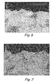
- FIGS. 6 and 7 are photographs of embodiments of this invention.
- FIG. 1 is a cross-sectional view of gas turbine engine 10 , in a turbofan embodiment.
- turbine engine 10 comprises fan 12 positioned in bypass duct 14 , with bypass duct 14 oriented about a turbine core comprising compressor (compressor section) 16 , combustor (or combustors) 18 and turbine (turbine section) 20 , arranged in flow series with upstream inlet 22 and downstream exhaust 24 .
- compressor compressor section
- combustor or combustors
- Compressor 16 comprises stages of compressor vanes 26 and blades 28 arranged in low pressure compressor (LPC) section 30 and high pressure compressor (LPC) section 32 .
- Turbine 20 comprises stages of turbine vanes 34 and turbine blades 36 arranged in high pressure turbine (HPT) section 38 and low pressure turbine (LPT) section 40 .
- HPT section 38 is coupled to HPC section 32 via HPT shaft 32 , forming the high pressure spool or high spool.
- LPT section 40 is coupled to LPC section 30 and fan 12 via LPT shaft 44 , forming the low pressure spool or low spool.
- HPT shaft 42 and LPT shaft 44 are typically coaxially mounted, with the high and low spools independently rotating about turbine axis (centerline) C L .
- Fan 12 comprises a number of fan airfoils circumferentially arranged around a fan disk or other rotating member, which is coupled (directly or indirectly) to LPC section 30 and driven by LPT shaft 44 .
- fan 12 is coupled to the fan spool via geared fan drive mechanism 46 , providing independent fan speed control.
- fan 12 is forward-mounted and provides thrust by accelerating flow downstream through bypass duct 14 , for example in a high-bypass configuration suitable for commercial and regional jet aircraft operations.
- fan 12 is an unducted fan or propeller assembly, in either a forward or aft-mounted configuration.
- turbine engine 10 comprises any of a high-bypass turbofan, a low-bypass turbofan or a turboprop engine, and the number of spools and the shaft configurations may vary.
- incoming airflow F I enters inlet 22 and divides into core flow F C and bypass flow F B , downstream of fan 12 .
- Core flow F C propagates along the core flowpath through compressor section 16 , combustor 18 and turbine section 20
- bypass flow F B propagates along the bypass flowpath through bypass duct 14 .
- LPC section 30 and HPC section 32 of compressor 16 are utilized to compress incoming air for combustor 18 , where fuel is introduced, mixed with air and ignited to produce hot combustion gas.
- fan 12 also provides some degree of compression (or pre-compression) to core flow F C , and LPC section 30 may be omitted.
- an additional intermediate spool is included, for example in a three-spool turboprop or turbofan configuration.
- Combustion gas exits combustor 18 and enters HPT section 38 of turbine 20 , encountering turbine vanes 34 and turbine blades 36 .
- Turbine vanes 34 turn and accelerate the flow, and turbine blades 36 generate lift for conversion to rotational energy via HPT shaft 42 , driving HPC section 32 of compressor 16 via HPT shaft 42 .
- Partially expanded combustion gas transitions from HPT section 38 to LPT section 40 , driving LPC section 30 and fan 12 via LPT shaft 44 .
- Exhaust flow exits LPT section 40 and turbine engine 10 via exhaust nozzle 24 .
- thermodynamic efficiency of turbine engine 10 is tied to the overall pressure ratio, as defined between the delivery pressure at inlet 22 and the compressed air pressure entering combustor 18 from compressor section 16 .
- a higher pressure ratio offers increased efficiency and improved performance, including greater specific thrust.
- High pressure ratios also result in increased peak gas path temperatures, higher core pressure and greater flow rates, increasing thermal and mechanical stress on engine components.
- the present invention is intended to be used with airfoils in turbine engines.
- airfoil is intended to cover both rotor blades and stator vanes.
- FIG. 2 and FIG. 3 disclose the invention with respect to interaction of a stator vane with a rotor.
- FIG. 4 and FIG. 5 disclose the invention with respect to interaction of a rotor blade with a stator casing or shroud.
- the coating of this invention may be used with either or both configurations.
- FIG. 2 is a cross section along line 2 - 2 of FIG. 1 of a casing 48 which has a rotor shaft 50 inside. Vanes 26 are attached to casing 48 and the gas path 52 is shown as the space between vanes 26 .
- Coating 60 corresponding to the coating of this invention, is on rotor shaft 50 such that the clearance C between coating 60 and vane tips 26 T of vanes 26 has the proper tolerance for operation of the engine, e.g., to serve as a seal to prevent leakage of air (thus reducing efficiency), while not interfering with relative movement of the vanes and rotor shaft.
- clearance C is expanded for purposes of illustration.
- clearance C may be, for example, about 25 to 55 about mils (about 635 to about 1400 microns) when the engine is cold to 0 to about 35 mils (about 889 microns) during engine operation depending on specific operations and previous rub events that may have occurred.
- the new rotor coating is strong enough to abrade the bare super alloy vane tips by themselves thereby eliminating necessity of an abradable coating.
- FIG. 2 and FIG. 3 show coating 60 in which includes metallic bond coat 62 and abrasive layer 66 .
- Metallic bond coat 62 is applied to rotor shaft 50 .
- Abrasive layer 66 is deposited on top of bond coat 62 and is the layer that first encounters vane tip 26 T.
- Coating 70 is provided on the inner diameter surface of casing or shroud 48 .
- Coating 70 includes a first metallic bond coat 72 that has been applied to the ID of stator casing 48 .
- stator casing 48 includes a shroud that forms a blade air seal.
- Abrasive layer 76 is formed on metallic bond coating 72 and is the layer that first encounters rotor tip 28 T.
- Bond coats 62 and 72 are thin, up to 10 mils, more specifically ranging from about 3 mils to about 7 mils (76 to 178 microns). Abrasive coatings 66 and 76 are much thicker than bond coats 62 and 72 , ranging from about 10 mils to about 19 mils (254 to 483 microns).
- Bond coats 62 and 72 may be formed of MCrAlY, the metal (M) can be nickel, iron, or cobalt, or combinations thereof and the alloying elements are chromium (Cr), aluminum (Al) and yttrium (Y).
- bond coats 62 and 64 may be 15-40% Cr 6-15% Al, 0.61 to 1.0%. Y and the balance is cobalt, nickel or iron and combinations thereof. Bond coat layers 62 and 72 are applied by plasma spraying.
- Abrasive layer 66 and 76 may be a porous or filled metallic or ceramic material such as SM2042, SM2043, Metco 105NS or Durabrade 2192 available from Sulzer Metco. SM2042 is described in U.S. Pat. No. 5,434,210, which is incorporated by reference herein in its entirety.
- suitable abrasive layer material varies with application and is typically a compromise between erosion resistance, wear ratio with vane or blade tips and durability in the subject environment.
- One example choice may be Metco 105NS aluminum oxide coating with a mechanically roughened surface in an application where low erosion rate of the coating is desired.
- Coatings 66 and 76 in this patent consist essentially of zirconia containing 11-14 wt. % yttria. Coatings 66 and 76 are applied by plasma spraying, followed by laser engraving to form pyramids 66 a and 76 a on the surface facing the airfoil, as seen in FIG. 3 and FIG. 5 .
- Ceramic coatings may be used, provided that the ceramic has a coating having a hardness of 7 or higher on the Mohs scale of mineral hardness. These may be selected from quartz, zirconia such as those discussed above, corundum and diamond.
- FIG. 6 and FIG. 7 are enlarged photographs of pyramids 66 a and 76 a of FIG. 3 and FIG. 5 .
- Pyramids 66 a and 76 a are formed by application of a laser engraving on the surface that will engage the airfoil.
- the pyramids 66 a and 76 a were formed using a IPG 20W Q-switched fiber laser with a Nutfield XLR8-10-YAG 2-axis Scan Head with an f-theta 100 mm lens providing a max spot size of 16 ⁇ m.
- the f-theta 100 mm lens alloed for a working distance of 3.85′′ in length.
- FIG. 6 represents a finely spaced grit pattern with grit spacing of 0.005′′, a texture height of 0.0015′′, grit side slope of 45 degrees with respect to the surface before laser treatment, and the grits are misaligned in the circumferential direction.
- FIG. 7 represents a coarsely spaced grit pattern with grit spacing of 0.010′′, texture height of 0.0015′′, grid side slope of 45 degrees and grits misaligned in the circumferential direction.
- the pattern in FIG. 6 was made at a power of 10 W, a speed of 900 mm/s, and a frequency of 40 kHz.
- Line length was 70 mm
- line width was 0.05 mm
- hatch distance was 0.004 mm
- line distance was 0.381 mm.
- the pattern in FIG. 7 was made at a power of 10 W, at a speed of 500 m/s, and a frequency of 40 kHz.
- Line length was 63.5 mm, line width of 0.126 mm, hatch distance of 0.004 mm and line distance of 0.381 mm.
- the laser beam melts and removes parts of the ceramic coatings 66 and 76 at an angle with respect to the plane of the rotor or shroud so that the metallic airfoil encounters a sharp edge and is abraded.
- Other laser systems and dimensions are within the scope of this invention.
- the laser engraved surface with the top of the surface has less than about 5% of the surface area of the base of the ceramic layer.
- the degree of misalignment of the rows of pyramids can range from 0° to about 90°.
- the pyramids 66 a and 76 a of FIGS. 6 and 7 are at a misalignment of 45° with respect to the circumferential direction of rotation about centerline C L .
- pyramids 66 a and 76 a form rows that are placed there by the laser action and the rows can be selectively aligned or misaligned as desired.
Abstract
Description
Claims (17)
Priority Applications (2)
| Application Number | Priority Date | Filing Date | Title |
|---|---|---|---|
| US12/911,004 US8770927B2 (en) | 2010-10-25 | 2010-10-25 | Abrasive cutter formed by thermal spray and post treatment |
| EP11186597.8A EP2455589B1 (en) | 2010-10-25 | 2011-10-25 | Abrasive cutter formed by thermal spray and post treatment |
Applications Claiming Priority (1)
| Application Number | Priority Date | Filing Date | Title |
|---|---|---|---|
| US12/911,004 US8770927B2 (en) | 2010-10-25 | 2010-10-25 | Abrasive cutter formed by thermal spray and post treatment |
Publications (2)
| Publication Number | Publication Date |
|---|---|
| US20120099985A1 US20120099985A1 (en) | 2012-04-26 |
| US8770927B2 true US8770927B2 (en) | 2014-07-08 |
Family
ID=45715412
Family Applications (1)
| Application Number | Title | Priority Date | Filing Date |
|---|---|---|---|
| US12/911,004 Active 2032-10-30 US8770927B2 (en) | 2010-10-25 | 2010-10-25 | Abrasive cutter formed by thermal spray and post treatment |
Country Status (2)
| Country | Link |
|---|---|
| US (1) | US8770927B2 (en) |
| EP (1) | EP2455589B1 (en) |
Cited By (3)
| Publication number | Priority date | Publication date | Assignee | Title |
|---|---|---|---|---|
| US20160010475A1 (en) * | 2013-03-12 | 2016-01-14 | United Technologies Corporation | Cantilever stator with vortex initiation feature |
| US20190107003A1 (en) * | 2016-04-08 | 2019-04-11 | United Technologies Corporation | Seal Geometries for Reduced Leakage in Gas Turbines and Methods of Forming |
| US11225913B2 (en) | 2015-02-19 | 2022-01-18 | Raytheon Technologies Corporation | Method of providing turbine engines with different thrust ratings |
Families Citing this family (5)
| Publication number | Priority date | Publication date | Assignee | Title |
|---|---|---|---|---|
| US10786875B2 (en) * | 2014-07-02 | 2020-09-29 | Raytheon Technologies Corporation | Abrasive preforms and manufacture and use methods |
| US10582192B2 (en) * | 2014-11-24 | 2020-03-03 | Samsung Electronics Co., Ltd. | Display apparatus |
| GB2536207B (en) * | 2015-03-03 | 2020-12-30 | Alcon Components Ltd | A brake caliper seal and a method of manufacturing a brake caliper seal |
| US11692490B2 (en) * | 2021-05-26 | 2023-07-04 | Doosan Heavy Industries & Construction Co., Ltd. | Gas turbine inner shroud with abradable surface feature |
| US11674448B2 (en) * | 2021-07-16 | 2023-06-13 | Raytheon Technologies Corporation | Seal system having silicon layer and barrier layer |
Citations (38)
| Publication number | Priority date | Publication date | Assignee | Title |
|---|---|---|---|---|
| US4227703A (en) | 1978-11-27 | 1980-10-14 | General Electric Company | Gas seal with tip of abrasive particles |
| US4238170A (en) | 1978-06-26 | 1980-12-09 | United Technologies Corporation | Blade tip seal for an axial flow rotary machine |
| US4588607A (en) | 1984-11-28 | 1986-05-13 | United Technologies Corporation | Method of applying continuously graded metallic-ceramic layer on metallic substrates |
| US4783341A (en) | 1987-05-04 | 1988-11-08 | United Technologies Corporation | Method and apparatus for measuring the density and hardness of porous plasma sprayed coatings |
| US4861618A (en) | 1986-10-30 | 1989-08-29 | United Technologies Corporation | Thermal barrier coating system |
| US4884820A (en) * | 1987-05-19 | 1989-12-05 | Union Carbide Corporation | Wear resistant, abrasive laser-engraved ceramic or metallic carbide surfaces for rotary labyrinth seal members |
| US4936745A (en) | 1988-12-16 | 1990-06-26 | United Technologies Corporation | Thin abradable ceramic air seal |
| US5113582A (en) | 1990-11-13 | 1992-05-19 | General Electric Company | Method for making a gas turbine engine component |
| US5434210A (en) | 1990-11-19 | 1995-07-18 | Sulzer Plasma Technik, Inc. | Thermal spray powders for abradable coatings, abradable coatings containing solid lubricants and methods of fabricating abradable coatings |
| US5536022A (en) | 1990-08-24 | 1996-07-16 | United Technologies Corporation | Plasma sprayed abradable seals for gas turbine engines |
| US5562404A (en) | 1994-12-23 | 1996-10-08 | United Technologies Corporation | Vaned passage hub treatment for cantilever stator vanes |
| US5645399A (en) | 1995-03-15 | 1997-07-08 | United Technologies Corporation | Gas turbine engine case coated with thermal barrier coating to control axial airfoil clearance |
| US5705231A (en) | 1995-09-26 | 1998-01-06 | United Technologies Corporation | Method of producing a segmented abradable ceramic coating system |
| US5715596A (en) | 1995-11-30 | 1998-02-10 | United Technologies Corporation | Brush seal for stator of a gas turbine engine case |
| US5879753A (en) | 1997-12-19 | 1999-03-09 | United Technologies Corporation | Thermal spray coating process for rotor blade tips using a rotatable holding fixture |
| US6089825A (en) | 1998-12-18 | 2000-07-18 | United Technologies Corporation | Abradable seal having improved properties and method of producing seal |
| US6177174B1 (en) | 1997-07-12 | 2001-01-23 | Mtu Motoren- Und Turbinen-Union Muenchen Gmbh | Armor coating for a metal engine component, and method of producing the same |
| US6190124B1 (en) | 1997-11-26 | 2001-02-20 | United Technologies Corporation | Columnar zirconium oxide abrasive coating for a gas turbine engine seal system |
| US6203021B1 (en) * | 1996-12-10 | 2001-03-20 | Chromalloy Gas Turbine Corporation | Abradable seal having a cut pattern |
| US6358002B1 (en) | 1998-06-18 | 2002-03-19 | United Technologies Corporation | Article having durable ceramic coating with localized abradable portion |
| US6383658B1 (en) | 1999-11-18 | 2002-05-07 | General Electric Company | Thermally sprayed coatings having an interface with controlled cleanliness |
| US6537021B2 (en) | 2001-06-06 | 2003-03-25 | Chromalloy Gas Turbine Corporation | Abradeable seal system |
| US20040005452A1 (en) | 2002-01-14 | 2004-01-08 | Dorfman Mitchell R. | High temperature spray dried composite abradable powder for combustion spraying and abradable barrier coating produced using same |
| US6703137B2 (en) | 2001-08-02 | 2004-03-09 | Siemens Westinghouse Power Corporation | Segmented thermal barrier coating and method of manufacturing the same |
| US20060140756A1 (en) | 2004-12-29 | 2006-06-29 | United Technologies Corporation | Gas turbine engine blade tip clearance apparatus and method |
| US7241108B2 (en) * | 2004-01-13 | 2007-07-10 | Rolls-Royce Plc | Cantilevered stator stage |
| US20080063520A1 (en) | 2006-09-12 | 2008-03-13 | United Technologies Corporation | Turbine engine compressor vanes |
| US20080087023A1 (en) | 2004-12-01 | 2008-04-17 | Suciu Gabriel L | Cantilevered Tip Turbine Engine |
| US20080219835A1 (en) | 2007-03-05 | 2008-09-11 | Melvin Freling | Abradable component for a gas turbine engine |
| US20080226879A1 (en) | 2007-03-13 | 2008-09-18 | United Technologies Corporation | Low stress metallic based coating |
| EP1985807A2 (en) | 2007-04-18 | 2008-10-29 | United Technologies Corporation | Seal for a gas turbine and corresponding manufacturing method |
| US20090017260A1 (en) | 2001-08-02 | 2009-01-15 | Kulkarni Anand A | Segmented thermal barrier coating |
| US7510370B2 (en) | 2005-02-01 | 2009-03-31 | Honeywell International Inc. | Turbine blade tip and shroud clearance control coating system |
| US20090097970A1 (en) | 2007-10-16 | 2009-04-16 | United Technologies Corp. | Systems and Methods Involving Abradable Air Seals |
| US20090136740A1 (en) * | 2007-11-28 | 2009-05-28 | Reynolds George H | Article having composite layer |
| US20090176110A1 (en) * | 2008-01-08 | 2009-07-09 | General Electric Company | Erosion and corrosion-resistant coating system and process therefor |
| US20100098923A1 (en) | 2006-10-05 | 2010-04-22 | United Technologies Corporation | Segmented abradable coatings and process (ES) for applying the same |
| US20100143103A1 (en) | 2008-12-10 | 2010-06-10 | Rolls-Royce Plc | Seal and a method of manufacturing a seal |
-
2010
- 2010-10-25 US US12/911,004 patent/US8770927B2/en active Active
-
2011
- 2011-10-25 EP EP11186597.8A patent/EP2455589B1/en active Active
Patent Citations (43)
| Publication number | Priority date | Publication date | Assignee | Title |
|---|---|---|---|---|
| US4238170A (en) | 1978-06-26 | 1980-12-09 | United Technologies Corporation | Blade tip seal for an axial flow rotary machine |
| US4227703A (en) | 1978-11-27 | 1980-10-14 | General Electric Company | Gas seal with tip of abrasive particles |
| US4588607A (en) | 1984-11-28 | 1986-05-13 | United Technologies Corporation | Method of applying continuously graded metallic-ceramic layer on metallic substrates |
| US4861618A (en) | 1986-10-30 | 1989-08-29 | United Technologies Corporation | Thermal barrier coating system |
| US4783341A (en) | 1987-05-04 | 1988-11-08 | United Technologies Corporation | Method and apparatus for measuring the density and hardness of porous plasma sprayed coatings |
| US4884820A (en) * | 1987-05-19 | 1989-12-05 | Union Carbide Corporation | Wear resistant, abrasive laser-engraved ceramic or metallic carbide surfaces for rotary labyrinth seal members |
| US4936745A (en) | 1988-12-16 | 1990-06-26 | United Technologies Corporation | Thin abradable ceramic air seal |
| US5780116A (en) | 1990-08-24 | 1998-07-14 | United Technologies Corporation | Method for producing an abradable seal |
| US5536022A (en) | 1990-08-24 | 1996-07-16 | United Technologies Corporation | Plasma sprayed abradable seals for gas turbine engines |
| US5113582A (en) | 1990-11-13 | 1992-05-19 | General Electric Company | Method for making a gas turbine engine component |
| US5434210A (en) | 1990-11-19 | 1995-07-18 | Sulzer Plasma Technik, Inc. | Thermal spray powders for abradable coatings, abradable coatings containing solid lubricants and methods of fabricating abradable coatings |
| US5562404A (en) | 1994-12-23 | 1996-10-08 | United Technologies Corporation | Vaned passage hub treatment for cantilever stator vanes |
| US5950308A (en) | 1994-12-23 | 1999-09-14 | United Technologies Corporation | Vaned passage hub treatment for cantilever stator vanes and method |
| US5645399A (en) | 1995-03-15 | 1997-07-08 | United Technologies Corporation | Gas turbine engine case coated with thermal barrier coating to control axial airfoil clearance |
| US5705231A (en) | 1995-09-26 | 1998-01-06 | United Technologies Corporation | Method of producing a segmented abradable ceramic coating system |
| US5780171A (en) | 1995-09-26 | 1998-07-14 | United Technologies Corporation | Gas turbine engine component |
| US6102656A (en) | 1995-09-26 | 2000-08-15 | United Technologies Corporation | Segmented abradable ceramic coating |
| US5715596A (en) | 1995-11-30 | 1998-02-10 | United Technologies Corporation | Brush seal for stator of a gas turbine engine case |
| US6203021B1 (en) * | 1996-12-10 | 2001-03-20 | Chromalloy Gas Turbine Corporation | Abradable seal having a cut pattern |
| US6177174B1 (en) | 1997-07-12 | 2001-01-23 | Mtu Motoren- Und Turbinen-Union Muenchen Gmbh | Armor coating for a metal engine component, and method of producing the same |
| US6190124B1 (en) | 1997-11-26 | 2001-02-20 | United Technologies Corporation | Columnar zirconium oxide abrasive coating for a gas turbine engine seal system |
| US5879753A (en) | 1997-12-19 | 1999-03-09 | United Technologies Corporation | Thermal spray coating process for rotor blade tips using a rotatable holding fixture |
| US6358002B1 (en) | 1998-06-18 | 2002-03-19 | United Technologies Corporation | Article having durable ceramic coating with localized abradable portion |
| US6089825A (en) | 1998-12-18 | 2000-07-18 | United Technologies Corporation | Abradable seal having improved properties and method of producing seal |
| US6383658B1 (en) | 1999-11-18 | 2002-05-07 | General Electric Company | Thermally sprayed coatings having an interface with controlled cleanliness |
| US6537021B2 (en) | 2001-06-06 | 2003-03-25 | Chromalloy Gas Turbine Corporation | Abradeable seal system |
| US20090017260A1 (en) | 2001-08-02 | 2009-01-15 | Kulkarni Anand A | Segmented thermal barrier coating |
| US6703137B2 (en) | 2001-08-02 | 2004-03-09 | Siemens Westinghouse Power Corporation | Segmented thermal barrier coating and method of manufacturing the same |
| US20040005452A1 (en) | 2002-01-14 | 2004-01-08 | Dorfman Mitchell R. | High temperature spray dried composite abradable powder for combustion spraying and abradable barrier coating produced using same |
| US7241108B2 (en) * | 2004-01-13 | 2007-07-10 | Rolls-Royce Plc | Cantilevered stator stage |
| US20080087023A1 (en) | 2004-12-01 | 2008-04-17 | Suciu Gabriel L | Cantilevered Tip Turbine Engine |
| US20060140756A1 (en) | 2004-12-29 | 2006-06-29 | United Technologies Corporation | Gas turbine engine blade tip clearance apparatus and method |
| US7407369B2 (en) | 2004-12-29 | 2008-08-05 | United Technologies Corporation | Gas turbine engine blade tip clearance apparatus and method |
| US7510370B2 (en) | 2005-02-01 | 2009-03-31 | Honeywell International Inc. | Turbine blade tip and shroud clearance control coating system |
| US20080063520A1 (en) | 2006-09-12 | 2008-03-13 | United Technologies Corporation | Turbine engine compressor vanes |
| US20100098923A1 (en) | 2006-10-05 | 2010-04-22 | United Technologies Corporation | Segmented abradable coatings and process (ES) for applying the same |
| US20080219835A1 (en) | 2007-03-05 | 2008-09-11 | Melvin Freling | Abradable component for a gas turbine engine |
| US20080226879A1 (en) | 2007-03-13 | 2008-09-18 | United Technologies Corporation | Low stress metallic based coating |
| EP1985807A2 (en) | 2007-04-18 | 2008-10-29 | United Technologies Corporation | Seal for a gas turbine and corresponding manufacturing method |
| US20090097970A1 (en) | 2007-10-16 | 2009-04-16 | United Technologies Corp. | Systems and Methods Involving Abradable Air Seals |
| US20090136740A1 (en) * | 2007-11-28 | 2009-05-28 | Reynolds George H | Article having composite layer |
| US20090176110A1 (en) * | 2008-01-08 | 2009-07-09 | General Electric Company | Erosion and corrosion-resistant coating system and process therefor |
| US20100143103A1 (en) | 2008-12-10 | 2010-06-10 | Rolls-Royce Plc | Seal and a method of manufacturing a seal |
Non-Patent Citations (4)
| Title |
|---|
| Article entitled "Increased Efficiency of Gas Turbines", New High-Temperature Seal System, Sulzer Technical Review Feb. 2008, Dieter Sporer et al., pp. 1-4. |
| Article entitled "On the Potential of Metal and Ceramic Based Abradables in Turbine Seal Applications", Proceedings of the Thirty-Sixth Turbomachinery Symposium-2007, Dieter Sporer et al., pp. 79-86. |
| Article entitled "On the Potential of Metal and Ceramic Based Abradables in Turbine Seal Applications", Proceedings of the Thirty-Sixth Turbomachinery Symposium—2007, Dieter Sporer et al., pp. 79-86. |
| European Search Report, mailed Apr. 19, 2012. |
Cited By (5)
| Publication number | Priority date | Publication date | Assignee | Title |
|---|---|---|---|---|
| US20160010475A1 (en) * | 2013-03-12 | 2016-01-14 | United Technologies Corporation | Cantilever stator with vortex initiation feature |
| US10240471B2 (en) * | 2013-03-12 | 2019-03-26 | United Technologies Corporation | Serrated outer surface for vortex initiation within the compressor stage of a gas turbine |
| US11225913B2 (en) | 2015-02-19 | 2022-01-18 | Raytheon Technologies Corporation | Method of providing turbine engines with different thrust ratings |
| US20190107003A1 (en) * | 2016-04-08 | 2019-04-11 | United Technologies Corporation | Seal Geometries for Reduced Leakage in Gas Turbines and Methods of Forming |
| US10794211B2 (en) * | 2016-04-08 | 2020-10-06 | Raytheon Technologies Corporation | Seal geometries for reduced leakage in gas turbines and methods of forming |
Also Published As
| Publication number | Publication date |
|---|---|
| EP2455589A1 (en) | 2012-05-23 |
| EP2455589B1 (en) | 2013-07-31 |
| US20120099985A1 (en) | 2012-04-26 |
Similar Documents
| Publication | Publication Date | Title |
|---|---|---|
| US8770926B2 (en) | Rough dense ceramic sealing surface in turbomachines | |
| US8770927B2 (en) | Abrasive cutter formed by thermal spray and post treatment | |
| EP2444516A1 (en) | Thermal spray coating process for compressor shafts | |
| EP2444513B1 (en) | Abrasive rotor shaft ceramic coating | |
| US10794211B2 (en) | Seal geometries for reduced leakage in gas turbines and methods of forming | |
| US11702950B2 (en) | Seal coating | |
| US9169740B2 (en) | Friable ceramic rotor shaft abrasive coating | |
| US20120189434A1 (en) | Coating with abradability proportional to interaction rate | |
| EP3055445B1 (en) | Aluminum alloy coating with rare earth and transition metal corrosion inhibitors | |
| EP3061850B1 (en) | Hard phaseless metallic coating for compressor blade tip | |
| US20120099973A1 (en) | Low density abradable coating with fine porosity | |
| US20120099971A1 (en) | Self dressing, mildly abrasive coating for clearance control | |
| EP2428593B1 (en) | Abradable coating with safety fuse | |
| EP2540868B1 (en) | Spall resistant abradable turbine air seal | |
| US20180087387A1 (en) | Compositions and methods for coating metal turbine blade tips | |
| EP2453110A1 (en) | Method of forming a seal in a gas turbine engine, corresponding blade airfoil and seal combination and gas turbine engine | |
| US20180135638A1 (en) | Ceramic coating composition for compressor casing and methods for forming the same |
Legal Events
| Date | Code | Title | Description |
|---|---|---|---|
| AS | Assignment |
Owner name: UNITED TECHNOLOGIES CORPORATION, CONNECTICUT Free format text: ASSIGNMENT OF ASSIGNORS INTEREST;ASSIGNORS:STROCK, CHRISTOPHER W.;GUO, CHANGSHENG;SIGNING DATES FROM 20100928 TO 20101004;REEL/FRAME:025186/0962 |
|
| STCF | Information on status: patent grant |
Free format text: PATENTED CASE |
|
| MAFP | Maintenance fee payment |
Free format text: PAYMENT OF MAINTENANCE FEE, 4TH YEAR, LARGE ENTITY (ORIGINAL EVENT CODE: M1551) Year of fee payment: 4 |
|
| AS | Assignment |
Owner name: RAYTHEON TECHNOLOGIES CORPORATION, MASSACHUSETTS Free format text: CHANGE OF NAME;ASSIGNOR:UNITED TECHNOLOGIES CORPORATION;REEL/FRAME:054062/0001 Effective date: 20200403 |
|
| AS | Assignment |
Owner name: RAYTHEON TECHNOLOGIES CORPORATION, CONNECTICUT Free format text: CORRECTIVE ASSIGNMENT TO CORRECT THE AND REMOVE PATENT APPLICATION NUMBER 11886281 AND ADD PATENT APPLICATION NUMBER 14846874. TO CORRECT THE RECEIVING PARTY ADDRESS PREVIOUSLY RECORDED AT REEL: 054062 FRAME: 0001. ASSIGNOR(S) HEREBY CONFIRMS THE CHANGE OF ADDRESS;ASSIGNOR:UNITED TECHNOLOGIES CORPORATION;REEL/FRAME:055659/0001 Effective date: 20200403 |
|
| MAFP | Maintenance fee payment |
Free format text: PAYMENT OF MAINTENANCE FEE, 8TH YEAR, LARGE ENTITY (ORIGINAL EVENT CODE: M1552); ENTITY STATUS OF PATENT OWNER: LARGE ENTITY Year of fee payment: 8 |
|
| AS | Assignment |
Owner name: RTX CORPORATION, CONNECTICUT Free format text: CHANGE OF NAME;ASSIGNOR:RAYTHEON TECHNOLOGIES CORPORATION;REEL/FRAME:064714/0001 Effective date: 20230714 |