US8771359B2 - Spinal implant device - Google Patents
Spinal implant device Download PDFInfo
- Publication number
- US8771359B2 US8771359B2 US12/957,451 US95745110A US8771359B2 US 8771359 B2 US8771359 B2 US 8771359B2 US 95745110 A US95745110 A US 95745110A US 8771359 B2 US8771359 B2 US 8771359B2
- Authority
- US
- United States
- Prior art keywords
- rod
- tip
- vertebral body
- width
- adjacent vertebral
- Prior art date
- Legal status (The legal status is an assumption and is not a legal conclusion. Google has not performed a legal analysis and makes no representation as to the accuracy of the status listed.)
- Expired - Fee Related, expires
Links
Images


Classifications
-
- A—HUMAN NECESSITIES
- A61—MEDICAL OR VETERINARY SCIENCE; HYGIENE
- A61F—FILTERS IMPLANTABLE INTO BLOOD VESSELS; PROSTHESES; DEVICES PROVIDING PATENCY TO, OR PREVENTING COLLAPSING OF, TUBULAR STRUCTURES OF THE BODY, e.g. STENTS; ORTHOPAEDIC, NURSING OR CONTRACEPTIVE DEVICES; FOMENTATION; TREATMENT OR PROTECTION OF EYES OR EARS; BANDAGES, DRESSINGS OR ABSORBENT PADS; FIRST-AID KITS
- A61F2/00—Filters implantable into blood vessels; Prostheses, i.e. artificial substitutes or replacements for parts of the body; Appliances for connecting them with the body; Devices providing patency to, or preventing collapsing of, tubular structures of the body, e.g. stents
- A61F2/02—Prostheses implantable into the body
- A61F2/30—Joints
- A61F2/44—Joints for the spine, e.g. vertebrae, spinal discs
- A61F2/4455—Joints for the spine, e.g. vertebrae, spinal discs for the fusion of spinal bodies, e.g. intervertebral fusion of adjacent spinal bodies, e.g. fusion cages
-
- A—HUMAN NECESSITIES
- A61—MEDICAL OR VETERINARY SCIENCE; HYGIENE
- A61B—DIAGNOSIS; SURGERY; IDENTIFICATION
- A61B17/00—Surgical instruments, devices or methods, e.g. tourniquets
- A61B17/16—Bone cutting, breaking or removal means other than saws, e.g. Osteoclasts; Drills or chisels for bones; Trepans
- A61B17/1662—Bone cutting, breaking or removal means other than saws, e.g. Osteoclasts; Drills or chisels for bones; Trepans for particular parts of the body
- A61B17/1671—Bone cutting, breaking or removal means other than saws, e.g. Osteoclasts; Drills or chisels for bones; Trepans for particular parts of the body for the spine
-
- A—HUMAN NECESSITIES
- A61—MEDICAL OR VETERINARY SCIENCE; HYGIENE
- A61B—DIAGNOSIS; SURGERY; IDENTIFICATION
- A61B17/00—Surgical instruments, devices or methods, e.g. tourniquets
- A61B17/56—Surgical instruments or methods for treatment of bones or joints; Devices specially adapted therefor
- A61B17/58—Surgical instruments or methods for treatment of bones or joints; Devices specially adapted therefor for osteosynthesis, e.g. bone plates, screws, setting implements or the like
- A61B17/88—Osteosynthesis instruments; Methods or means for implanting or extracting internal or external fixation devices
- A61B17/8802—Equipment for handling bone cement or other fluid fillers
- A61B17/8841—Tools specially adapted to engage a prosthesis
-
- A—HUMAN NECESSITIES
- A61—MEDICAL OR VETERINARY SCIENCE; HYGIENE
- A61F—FILTERS IMPLANTABLE INTO BLOOD VESSELS; PROSTHESES; DEVICES PROVIDING PATENCY TO, OR PREVENTING COLLAPSING OF, TUBULAR STRUCTURES OF THE BODY, e.g. STENTS; ORTHOPAEDIC, NURSING OR CONTRACEPTIVE DEVICES; FOMENTATION; TREATMENT OR PROTECTION OF EYES OR EARS; BANDAGES, DRESSINGS OR ABSORBENT PADS; FIRST-AID KITS
- A61F2/00—Filters implantable into blood vessels; Prostheses, i.e. artificial substitutes or replacements for parts of the body; Appliances for connecting them with the body; Devices providing patency to, or preventing collapsing of, tubular structures of the body, e.g. stents
- A61F2/02—Prostheses implantable into the body
- A61F2/30—Joints
- A61F2/44—Joints for the spine, e.g. vertebrae, spinal discs
-
- A—HUMAN NECESSITIES
- A61—MEDICAL OR VETERINARY SCIENCE; HYGIENE
- A61F—FILTERS IMPLANTABLE INTO BLOOD VESSELS; PROSTHESES; DEVICES PROVIDING PATENCY TO, OR PREVENTING COLLAPSING OF, TUBULAR STRUCTURES OF THE BODY, e.g. STENTS; ORTHOPAEDIC, NURSING OR CONTRACEPTIVE DEVICES; FOMENTATION; TREATMENT OR PROTECTION OF EYES OR EARS; BANDAGES, DRESSINGS OR ABSORBENT PADS; FIRST-AID KITS
- A61F2/00—Filters implantable into blood vessels; Prostheses, i.e. artificial substitutes or replacements for parts of the body; Appliances for connecting them with the body; Devices providing patency to, or preventing collapsing of, tubular structures of the body, e.g. stents
- A61F2/02—Prostheses implantable into the body
- A61F2/30—Joints
- A61F2/46—Special tools or methods for implanting or extracting artificial joints, accessories, bone grafts or substitutes, or particular adaptations therefor
- A61F2/4603—Special tools or methods for implanting or extracting artificial joints, accessories, bone grafts or substitutes, or particular adaptations therefor for insertion or extraction of endoprosthetic joints or of accessories thereof
- A61F2/4611—Special tools or methods for implanting or extracting artificial joints, accessories, bone grafts or substitutes, or particular adaptations therefor for insertion or extraction of endoprosthetic joints or of accessories thereof of spinal prostheses
-
- A—HUMAN NECESSITIES
- A61—MEDICAL OR VETERINARY SCIENCE; HYGIENE
- A61F—FILTERS IMPLANTABLE INTO BLOOD VESSELS; PROSTHESES; DEVICES PROVIDING PATENCY TO, OR PREVENTING COLLAPSING OF, TUBULAR STRUCTURES OF THE BODY, e.g. STENTS; ORTHOPAEDIC, NURSING OR CONTRACEPTIVE DEVICES; FOMENTATION; TREATMENT OR PROTECTION OF EYES OR EARS; BANDAGES, DRESSINGS OR ABSORBENT PADS; FIRST-AID KITS
- A61F2/00—Filters implantable into blood vessels; Prostheses, i.e. artificial substitutes or replacements for parts of the body; Appliances for connecting them with the body; Devices providing patency to, or preventing collapsing of, tubular structures of the body, e.g. stents
- A61F2/02—Prostheses implantable into the body
- A61F2/30—Joints
- A61F2002/30001—Additional features of subject-matter classified in A61F2/28, A61F2/30 and subgroups thereof
- A61F2002/30108—Shapes
- A61F2002/30199—Three-dimensional shapes
- A61F2002/30205—Three-dimensional shapes conical
- A61F2002/3021—Three-dimensional shapes conical frustoconical
-
- A—HUMAN NECESSITIES
- A61—MEDICAL OR VETERINARY SCIENCE; HYGIENE
- A61F—FILTERS IMPLANTABLE INTO BLOOD VESSELS; PROSTHESES; DEVICES PROVIDING PATENCY TO, OR PREVENTING COLLAPSING OF, TUBULAR STRUCTURES OF THE BODY, e.g. STENTS; ORTHOPAEDIC, NURSING OR CONTRACEPTIVE DEVICES; FOMENTATION; TREATMENT OR PROTECTION OF EYES OR EARS; BANDAGES, DRESSINGS OR ABSORBENT PADS; FIRST-AID KITS
- A61F2/00—Filters implantable into blood vessels; Prostheses, i.e. artificial substitutes or replacements for parts of the body; Appliances for connecting them with the body; Devices providing patency to, or preventing collapsing of, tubular structures of the body, e.g. stents
- A61F2/02—Prostheses implantable into the body
- A61F2/30—Joints
- A61F2002/30001—Additional features of subject-matter classified in A61F2/28, A61F2/30 and subgroups thereof
- A61F2002/30108—Shapes
- A61F2002/30199—Three-dimensional shapes
- A61F2002/30224—Three-dimensional shapes cylindrical
- A61F2002/30235—Three-dimensional shapes cylindrical tubular, e.g. sleeves
-
- A—HUMAN NECESSITIES
- A61—MEDICAL OR VETERINARY SCIENCE; HYGIENE
- A61F—FILTERS IMPLANTABLE INTO BLOOD VESSELS; PROSTHESES; DEVICES PROVIDING PATENCY TO, OR PREVENTING COLLAPSING OF, TUBULAR STRUCTURES OF THE BODY, e.g. STENTS; ORTHOPAEDIC, NURSING OR CONTRACEPTIVE DEVICES; FOMENTATION; TREATMENT OR PROTECTION OF EYES OR EARS; BANDAGES, DRESSINGS OR ABSORBENT PADS; FIRST-AID KITS
- A61F2/00—Filters implantable into blood vessels; Prostheses, i.e. artificial substitutes or replacements for parts of the body; Appliances for connecting them with the body; Devices providing patency to, or preventing collapsing of, tubular structures of the body, e.g. stents
- A61F2/02—Prostheses implantable into the body
- A61F2/30—Joints
- A61F2002/30001—Additional features of subject-matter classified in A61F2/28, A61F2/30 and subgroups thereof
- A61F2002/30108—Shapes
- A61F2002/30199—Three-dimensional shapes
- A61F2002/30306—Three-dimensional shapes harpoon-shaped
-
- A—HUMAN NECESSITIES
- A61—MEDICAL OR VETERINARY SCIENCE; HYGIENE
- A61F—FILTERS IMPLANTABLE INTO BLOOD VESSELS; PROSTHESES; DEVICES PROVIDING PATENCY TO, OR PREVENTING COLLAPSING OF, TUBULAR STRUCTURES OF THE BODY, e.g. STENTS; ORTHOPAEDIC, NURSING OR CONTRACEPTIVE DEVICES; FOMENTATION; TREATMENT OR PROTECTION OF EYES OR EARS; BANDAGES, DRESSINGS OR ABSORBENT PADS; FIRST-AID KITS
- A61F2/00—Filters implantable into blood vessels; Prostheses, i.e. artificial substitutes or replacements for parts of the body; Appliances for connecting them with the body; Devices providing patency to, or preventing collapsing of, tubular structures of the body, e.g. stents
- A61F2/02—Prostheses implantable into the body
- A61F2/30—Joints
- A61F2002/30001—Additional features of subject-matter classified in A61F2/28, A61F2/30 and subgroups thereof
- A61F2002/30316—The prosthesis having different structural features at different locations within the same prosthesis; Connections between prosthetic parts; Special structural features of bone or joint prostheses not otherwise provided for
- A61F2002/30329—Connections or couplings between prosthetic parts, e.g. between modular parts; Connecting elements
- A61F2002/30433—Connections or couplings between prosthetic parts, e.g. between modular parts; Connecting elements using additional screws, bolts, dowels, rivets or washers e.g. connecting screws
-
- A—HUMAN NECESSITIES
- A61—MEDICAL OR VETERINARY SCIENCE; HYGIENE
- A61F—FILTERS IMPLANTABLE INTO BLOOD VESSELS; PROSTHESES; DEVICES PROVIDING PATENCY TO, OR PREVENTING COLLAPSING OF, TUBULAR STRUCTURES OF THE BODY, e.g. STENTS; ORTHOPAEDIC, NURSING OR CONTRACEPTIVE DEVICES; FOMENTATION; TREATMENT OR PROTECTION OF EYES OR EARS; BANDAGES, DRESSINGS OR ABSORBENT PADS; FIRST-AID KITS
- A61F2/00—Filters implantable into blood vessels; Prostheses, i.e. artificial substitutes or replacements for parts of the body; Appliances for connecting them with the body; Devices providing patency to, or preventing collapsing of, tubular structures of the body, e.g. stents
- A61F2/02—Prostheses implantable into the body
- A61F2/30—Joints
- A61F2002/30001—Additional features of subject-matter classified in A61F2/28, A61F2/30 and subgroups thereof
- A61F2002/30316—The prosthesis having different structural features at different locations within the same prosthesis; Connections between prosthetic parts; Special structural features of bone or joint prostheses not otherwise provided for
- A61F2002/30329—Connections or couplings between prosthetic parts, e.g. between modular parts; Connecting elements
- A61F2002/30476—Connections or couplings between prosthetic parts, e.g. between modular parts; Connecting elements locked by an additional locking mechanism
- A61F2002/30484—Mechanically expandable devices located on the first prosthetic part for locking into or onto the second prosthetic part
-
- A—HUMAN NECESSITIES
- A61—MEDICAL OR VETERINARY SCIENCE; HYGIENE
- A61F—FILTERS IMPLANTABLE INTO BLOOD VESSELS; PROSTHESES; DEVICES PROVIDING PATENCY TO, OR PREVENTING COLLAPSING OF, TUBULAR STRUCTURES OF THE BODY, e.g. STENTS; ORTHOPAEDIC, NURSING OR CONTRACEPTIVE DEVICES; FOMENTATION; TREATMENT OR PROTECTION OF EYES OR EARS; BANDAGES, DRESSINGS OR ABSORBENT PADS; FIRST-AID KITS
- A61F2/00—Filters implantable into blood vessels; Prostheses, i.e. artificial substitutes or replacements for parts of the body; Appliances for connecting them with the body; Devices providing patency to, or preventing collapsing of, tubular structures of the body, e.g. stents
- A61F2/02—Prostheses implantable into the body
- A61F2/30—Joints
- A61F2002/30001—Additional features of subject-matter classified in A61F2/28, A61F2/30 and subgroups thereof
- A61F2002/30316—The prosthesis having different structural features at different locations within the same prosthesis; Connections between prosthetic parts; Special structural features of bone or joint prostheses not otherwise provided for
- A61F2002/30329—Connections or couplings between prosthetic parts, e.g. between modular parts; Connecting elements
- A61F2002/30476—Connections or couplings between prosthetic parts, e.g. between modular parts; Connecting elements locked by an additional locking mechanism
- A61F2002/30487—Circumferential cooperating grooves and beads on cooperating lateral surfaces of a mainly longitudinal connection
-
- A—HUMAN NECESSITIES
- A61—MEDICAL OR VETERINARY SCIENCE; HYGIENE
- A61F—FILTERS IMPLANTABLE INTO BLOOD VESSELS; PROSTHESES; DEVICES PROVIDING PATENCY TO, OR PREVENTING COLLAPSING OF, TUBULAR STRUCTURES OF THE BODY, e.g. STENTS; ORTHOPAEDIC, NURSING OR CONTRACEPTIVE DEVICES; FOMENTATION; TREATMENT OR PROTECTION OF EYES OR EARS; BANDAGES, DRESSINGS OR ABSORBENT PADS; FIRST-AID KITS
- A61F2/00—Filters implantable into blood vessels; Prostheses, i.e. artificial substitutes or replacements for parts of the body; Appliances for connecting them with the body; Devices providing patency to, or preventing collapsing of, tubular structures of the body, e.g. stents
- A61F2/02—Prostheses implantable into the body
- A61F2/30—Joints
- A61F2002/30001—Additional features of subject-matter classified in A61F2/28, A61F2/30 and subgroups thereof
- A61F2002/30316—The prosthesis having different structural features at different locations within the same prosthesis; Connections between prosthetic parts; Special structural features of bone or joint prostheses not otherwise provided for
- A61F2002/30329—Connections or couplings between prosthetic parts, e.g. between modular parts; Connecting elements
- A61F2002/30476—Connections or couplings between prosthetic parts, e.g. between modular parts; Connecting elements locked by an additional locking mechanism
- A61F2002/30495—Connections or couplings between prosthetic parts, e.g. between modular parts; Connecting elements locked by an additional locking mechanism using a locking ring
-
- A—HUMAN NECESSITIES
- A61—MEDICAL OR VETERINARY SCIENCE; HYGIENE
- A61F—FILTERS IMPLANTABLE INTO BLOOD VESSELS; PROSTHESES; DEVICES PROVIDING PATENCY TO, OR PREVENTING COLLAPSING OF, TUBULAR STRUCTURES OF THE BODY, e.g. STENTS; ORTHOPAEDIC, NURSING OR CONTRACEPTIVE DEVICES; FOMENTATION; TREATMENT OR PROTECTION OF EYES OR EARS; BANDAGES, DRESSINGS OR ABSORBENT PADS; FIRST-AID KITS
- A61F2/00—Filters implantable into blood vessels; Prostheses, i.e. artificial substitutes or replacements for parts of the body; Appliances for connecting them with the body; Devices providing patency to, or preventing collapsing of, tubular structures of the body, e.g. stents
- A61F2/02—Prostheses implantable into the body
- A61F2/30—Joints
- A61F2002/30001—Additional features of subject-matter classified in A61F2/28, A61F2/30 and subgroups thereof
- A61F2002/30316—The prosthesis having different structural features at different locations within the same prosthesis; Connections between prosthetic parts; Special structural features of bone or joint prostheses not otherwise provided for
- A61F2002/30535—Special structural features of bone or joint prostheses not otherwise provided for
- A61F2002/30537—Special structural features of bone or joint prostheses not otherwise provided for adjustable
- A61F2002/3055—Special structural features of bone or joint prostheses not otherwise provided for adjustable for adjusting length
-
- A—HUMAN NECESSITIES
- A61—MEDICAL OR VETERINARY SCIENCE; HYGIENE
- A61F—FILTERS IMPLANTABLE INTO BLOOD VESSELS; PROSTHESES; DEVICES PROVIDING PATENCY TO, OR PREVENTING COLLAPSING OF, TUBULAR STRUCTURES OF THE BODY, e.g. STENTS; ORTHOPAEDIC, NURSING OR CONTRACEPTIVE DEVICES; FOMENTATION; TREATMENT OR PROTECTION OF EYES OR EARS; BANDAGES, DRESSINGS OR ABSORBENT PADS; FIRST-AID KITS
- A61F2/00—Filters implantable into blood vessels; Prostheses, i.e. artificial substitutes or replacements for parts of the body; Appliances for connecting them with the body; Devices providing patency to, or preventing collapsing of, tubular structures of the body, e.g. stents
- A61F2/02—Prostheses implantable into the body
- A61F2/30—Joints
- A61F2002/30001—Additional features of subject-matter classified in A61F2/28, A61F2/30 and subgroups thereof
- A61F2002/30316—The prosthesis having different structural features at different locations within the same prosthesis; Connections between prosthetic parts; Special structural features of bone or joint prostheses not otherwise provided for
- A61F2002/30535—Special structural features of bone or joint prostheses not otherwise provided for
- A61F2002/30579—Special structural features of bone or joint prostheses not otherwise provided for with mechanically expandable devices, e.g. fixation devices
-
- A—HUMAN NECESSITIES
- A61—MEDICAL OR VETERINARY SCIENCE; HYGIENE
- A61F—FILTERS IMPLANTABLE INTO BLOOD VESSELS; PROSTHESES; DEVICES PROVIDING PATENCY TO, OR PREVENTING COLLAPSING OF, TUBULAR STRUCTURES OF THE BODY, e.g. STENTS; ORTHOPAEDIC, NURSING OR CONTRACEPTIVE DEVICES; FOMENTATION; TREATMENT OR PROTECTION OF EYES OR EARS; BANDAGES, DRESSINGS OR ABSORBENT PADS; FIRST-AID KITS
- A61F2/00—Filters implantable into blood vessels; Prostheses, i.e. artificial substitutes or replacements for parts of the body; Appliances for connecting them with the body; Devices providing patency to, or preventing collapsing of, tubular structures of the body, e.g. stents
- A61F2/02—Prostheses implantable into the body
- A61F2/30—Joints
- A61F2002/30001—Additional features of subject-matter classified in A61F2/28, A61F2/30 and subgroups thereof
- A61F2002/30316—The prosthesis having different structural features at different locations within the same prosthesis; Connections between prosthetic parts; Special structural features of bone or joint prostheses not otherwise provided for
- A61F2002/30535—Special structural features of bone or joint prostheses not otherwise provided for
- A61F2002/30581—Special structural features of bone or joint prostheses not otherwise provided for having a pocket filled with fluid, e.g. liquid
- A61F2002/30583—Special structural features of bone or joint prostheses not otherwise provided for having a pocket filled with fluid, e.g. liquid filled with hardenable fluid, e.g. curable in-situ
-
- A—HUMAN NECESSITIES
- A61—MEDICAL OR VETERINARY SCIENCE; HYGIENE
- A61F—FILTERS IMPLANTABLE INTO BLOOD VESSELS; PROSTHESES; DEVICES PROVIDING PATENCY TO, OR PREVENTING COLLAPSING OF, TUBULAR STRUCTURES OF THE BODY, e.g. STENTS; ORTHOPAEDIC, NURSING OR CONTRACEPTIVE DEVICES; FOMENTATION; TREATMENT OR PROTECTION OF EYES OR EARS; BANDAGES, DRESSINGS OR ABSORBENT PADS; FIRST-AID KITS
- A61F2/00—Filters implantable into blood vessels; Prostheses, i.e. artificial substitutes or replacements for parts of the body; Appliances for connecting them with the body; Devices providing patency to, or preventing collapsing of, tubular structures of the body, e.g. stents
- A61F2/02—Prostheses implantable into the body
- A61F2/30—Joints
- A61F2002/30001—Additional features of subject-matter classified in A61F2/28, A61F2/30 and subgroups thereof
- A61F2002/30316—The prosthesis having different structural features at different locations within the same prosthesis; Connections between prosthetic parts; Special structural features of bone or joint prostheses not otherwise provided for
- A61F2002/30535—Special structural features of bone or joint prostheses not otherwise provided for
- A61F2002/30593—Special structural features of bone or joint prostheses not otherwise provided for hollow
-
- A—HUMAN NECESSITIES
- A61—MEDICAL OR VETERINARY SCIENCE; HYGIENE
- A61F—FILTERS IMPLANTABLE INTO BLOOD VESSELS; PROSTHESES; DEVICES PROVIDING PATENCY TO, OR PREVENTING COLLAPSING OF, TUBULAR STRUCTURES OF THE BODY, e.g. STENTS; ORTHOPAEDIC, NURSING OR CONTRACEPTIVE DEVICES; FOMENTATION; TREATMENT OR PROTECTION OF EYES OR EARS; BANDAGES, DRESSINGS OR ABSORBENT PADS; FIRST-AID KITS
- A61F2/00—Filters implantable into blood vessels; Prostheses, i.e. artificial substitutes or replacements for parts of the body; Appliances for connecting them with the body; Devices providing patency to, or preventing collapsing of, tubular structures of the body, e.g. stents
- A61F2/02—Prostheses implantable into the body
- A61F2/30—Joints
- A61F2/30767—Special external or bone-contacting surface, e.g. coating for improving bone ingrowth
- A61F2/30771—Special external or bone-contacting surface, e.g. coating for improving bone ingrowth applied in original prostheses, e.g. holes or grooves
- A61F2002/30772—Apertures or holes, e.g. of circular cross section
-
- A—HUMAN NECESSITIES
- A61—MEDICAL OR VETERINARY SCIENCE; HYGIENE
- A61F—FILTERS IMPLANTABLE INTO BLOOD VESSELS; PROSTHESES; DEVICES PROVIDING PATENCY TO, OR PREVENTING COLLAPSING OF, TUBULAR STRUCTURES OF THE BODY, e.g. STENTS; ORTHOPAEDIC, NURSING OR CONTRACEPTIVE DEVICES; FOMENTATION; TREATMENT OR PROTECTION OF EYES OR EARS; BANDAGES, DRESSINGS OR ABSORBENT PADS; FIRST-AID KITS
- A61F2/00—Filters implantable into blood vessels; Prostheses, i.e. artificial substitutes or replacements for parts of the body; Appliances for connecting them with the body; Devices providing patency to, or preventing collapsing of, tubular structures of the body, e.g. stents
- A61F2/02—Prostheses implantable into the body
- A61F2/30—Joints
- A61F2/30767—Special external or bone-contacting surface, e.g. coating for improving bone ingrowth
- A61F2/30771—Special external or bone-contacting surface, e.g. coating for improving bone ingrowth applied in original prostheses, e.g. holes or grooves
- A61F2002/3082—Grooves
-
- A—HUMAN NECESSITIES
- A61—MEDICAL OR VETERINARY SCIENCE; HYGIENE
- A61F—FILTERS IMPLANTABLE INTO BLOOD VESSELS; PROSTHESES; DEVICES PROVIDING PATENCY TO, OR PREVENTING COLLAPSING OF, TUBULAR STRUCTURES OF THE BODY, e.g. STENTS; ORTHOPAEDIC, NURSING OR CONTRACEPTIVE DEVICES; FOMENTATION; TREATMENT OR PROTECTION OF EYES OR EARS; BANDAGES, DRESSINGS OR ABSORBENT PADS; FIRST-AID KITS
- A61F2/00—Filters implantable into blood vessels; Prostheses, i.e. artificial substitutes or replacements for parts of the body; Appliances for connecting them with the body; Devices providing patency to, or preventing collapsing of, tubular structures of the body, e.g. stents
- A61F2/02—Prostheses implantable into the body
- A61F2/30—Joints
- A61F2/30767—Special external or bone-contacting surface, e.g. coating for improving bone ingrowth
- A61F2/30771—Special external or bone-contacting surface, e.g. coating for improving bone ingrowth applied in original prostheses, e.g. holes or grooves
- A61F2002/3085—Special external or bone-contacting surface, e.g. coating for improving bone ingrowth applied in original prostheses, e.g. holes or grooves with a threaded, e.g. self-tapping, bone-engaging surface, e.g. external surface
-
- A—HUMAN NECESSITIES
- A61—MEDICAL OR VETERINARY SCIENCE; HYGIENE
- A61F—FILTERS IMPLANTABLE INTO BLOOD VESSELS; PROSTHESES; DEVICES PROVIDING PATENCY TO, OR PREVENTING COLLAPSING OF, TUBULAR STRUCTURES OF THE BODY, e.g. STENTS; ORTHOPAEDIC, NURSING OR CONTRACEPTIVE DEVICES; FOMENTATION; TREATMENT OR PROTECTION OF EYES OR EARS; BANDAGES, DRESSINGS OR ABSORBENT PADS; FIRST-AID KITS
- A61F2/00—Filters implantable into blood vessels; Prostheses, i.e. artificial substitutes or replacements for parts of the body; Appliances for connecting them with the body; Devices providing patency to, or preventing collapsing of, tubular structures of the body, e.g. stents
- A61F2/02—Prostheses implantable into the body
- A61F2/30—Joints
- A61F2/46—Special tools or methods for implanting or extracting artificial joints, accessories, bone grafts or substitutes, or particular adaptations therefor
- A61F2/4603—Special tools or methods for implanting or extracting artificial joints, accessories, bone grafts or substitutes, or particular adaptations therefor for insertion or extraction of endoprosthetic joints or of accessories thereof
- A61F2002/4622—Special tools or methods for implanting or extracting artificial joints, accessories, bone grafts or substitutes, or particular adaptations therefor for insertion or extraction of endoprosthetic joints or of accessories thereof having the shape of a forceps or a clamp
-
- A—HUMAN NECESSITIES
- A61—MEDICAL OR VETERINARY SCIENCE; HYGIENE
- A61F—FILTERS IMPLANTABLE INTO BLOOD VESSELS; PROSTHESES; DEVICES PROVIDING PATENCY TO, OR PREVENTING COLLAPSING OF, TUBULAR STRUCTURES OF THE BODY, e.g. STENTS; ORTHOPAEDIC, NURSING OR CONTRACEPTIVE DEVICES; FOMENTATION; TREATMENT OR PROTECTION OF EYES OR EARS; BANDAGES, DRESSINGS OR ABSORBENT PADS; FIRST-AID KITS
- A61F2310/00—Prostheses classified in A61F2/28 or A61F2/30 - A61F2/44 being constructed from or coated with a particular material
- A61F2310/00005—The prosthesis being constructed from a particular material
- A61F2310/00011—Metals or alloys
- A61F2310/00017—Iron- or Fe-based alloys, e.g. stainless steel
-
- A—HUMAN NECESSITIES
- A61—MEDICAL OR VETERINARY SCIENCE; HYGIENE
- A61F—FILTERS IMPLANTABLE INTO BLOOD VESSELS; PROSTHESES; DEVICES PROVIDING PATENCY TO, OR PREVENTING COLLAPSING OF, TUBULAR STRUCTURES OF THE BODY, e.g. STENTS; ORTHOPAEDIC, NURSING OR CONTRACEPTIVE DEVICES; FOMENTATION; TREATMENT OR PROTECTION OF EYES OR EARS; BANDAGES, DRESSINGS OR ABSORBENT PADS; FIRST-AID KITS
- A61F2310/00—Prostheses classified in A61F2/28 or A61F2/30 - A61F2/44 being constructed from or coated with a particular material
- A61F2310/00005—The prosthesis being constructed from a particular material
- A61F2310/00011—Metals or alloys
- A61F2310/00023—Titanium or titanium-based alloys, e.g. Ti-Ni alloys
Definitions
- the present specification relates generally to medical devices and more particularly relate to a spinal implant device.
- a healthy spine is important to quality of life. In addition to muscular-skeletal support, it is also the central pathway for the nervous system. Many spinal defects can occur which may be mitigated or even repaired through spinal surgery.
- Corpectomy is one particular type of spinal surgery that typically involves removal of a portion of a vertebral body and/or adjacent intervertebral discs. Such removal is often followed by a reconstruction procedure to provide the mechanical support that is lost by the removal.
- the device is substantially tubular and is comprised of two hollow rods that coaxially slide on one another.
- the device can thus then expand in length and can be locked or fixed at a particular length.
- the device is hollow to configure a malleable trocar to be placed into the device.
- PMMA polymethymethacrylate
- this device can be locked at a desired length by crimping it or locking it using other fastening means.
- the device can be further designed to have threads on both sides of the implant so as to screw into the body above or below. It can be cannulated or noncannulated/solid.
- the device can be configured in various dimensions and diameters for the appropriate purpose.
- the device may be particularly suitable for sites that are not amenable to traditional implants.
- the device is contemplated for use in, as a non-limiting example, any corpectomy defect.
- the device can be sized differently for large or small spines.
- the device may also be used for spines with osteoporotic bone or difficult to access places.
- the device may be used for patients with cancer who need instant stabilization.
- FIG. 1 shows a side-sectional view of a spinal implant device.
- FIG. 2 shows the spinal implant device of FIG. 1 with character reference labels.
- FIG. 3 shows the spinal implant device of FIG. 1 and FIG. 2 in an extended position, in contrast to the injection position shown in FIG. 1 and FIG. 2 .
- FIG. 4 shows the spinal implant device of FIG. 3 having a crimp applied to its diameter to keep each hollow rod fixed in relation to each other.
- FIG. 5 shows the spinal implant device of FIG. 1 in situ and ready for deployment.
- FIG. 6 shows a kit of example surgical tools instruments can be used to deploy the spinal implant device of FIG. 1 .
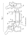
- FIG. 7 shows the spinal implant device of FIG. 5 during deployment using the instruments from FIG. 6 .
- FIG. 8 shows the spinal implant device of FIG. 7 during injection of bone cement via the spinal implant device during deployment using the instruments from FIG. 6 .
- FIG. 9 shows the spinal implant device of FIG. 8 during further deployment of the device into surrounding vertebra using the instruments from FIG. 6 .
- FIG. 10 shows the spinal implant device of FIG. 9 fully deployed.
- FIG. 11 shows an alternative embodiment utilizing a set screw rather than a crimp.
- FIG. 12 shows an alternative embodiment utilizing a lock ring which can be used rather than a crimp.
- FIG. 13 shows the lock ring of FIG. 12 in use.
- FIG. 14 shows an alternative embodiment with forked ends for each rod.
- FIG. 15 shows an alternative embodiment wherein one of the rods is solid and has a channel for flowing bone cement therealong.
- FIG. 16 is an end view of the solid rod of FIG. 15 through the lines XVI-XVI.
- FIG. 17 shows another surgical instrument that can be used with the spinal implant devices.
- FIG. 18 shows an alternative embodiment for the spinal implant device of FIG. 1 and surgical instruments that can be used therewith.
- FIG. 19 shows the use of the lock ring from FIG. 12 to secure each rod as part of another embodiment.
- FIG. 20 shows a hollowing instrument as another embodiment.
- FIG. 21 shows an alternative embodiment with a drip tray.
- FIG. 22 shows an end view of the drip tray of FIG. 20 .
- Device 50 can be made from any suitable non-toxic or bio-compatible material, such as medical-implant grade stainless steel or plastic.
- Other materials can include titanium, polyetherketone (PEEK), polyetherketone (PEK), polyetherketoneketone (PEKK), polyetherimide, or polyphenylsulfone, and bismuth trioxide (BiO 3 ) or other material with radioopacity such that it can be viewed under an imaging beam with reduced or minimal artifacts.
- FIG. 1 shows device 50 without specific character reference labels
- FIG. 2 includes such labels.
- device 50 comprises a first hollow rod 54 that is configured to slidably receive a second hollow rod 58 therein.
- First hollow rod 54 comprises a distal end 62 and a proximal end 66 .
- a tapered section 70 and a cylindrical section 74 interconnects distal end 62 and proximal end 66 .
- Distal end 62 comprises an opening 78 that communicates the interior of device 50 with the exterior of device 50 .
- Tapered section 70 comprises an angle A and a length B that is configured so that tapered section 70 can be driven into a vertebral body.
- Cylindrical section 74 comprises a length C that is about half the distance of a reconstruction space left by a corpectomy. Further understanding about the selection of length C will become apparent from the following discussion. Cylindrical section 74 has a substantially uniform inside diameter D along its length ending at the wider end of tapered section 70 .
- Diameter of opening 78 can be selected to be forty percent of diameter D, and likewise the diameter of opening 110 can be selected to be forty percent of diameter H.
- the taper, as defined by B and A, and by F and E. Can be selected so that B is about .5 cm and F is about .5 cm.
- the angles A and E can be selected to substantially correspond to the taper of the trocar chosen to make a pilot hole in the target vertebral body.
- Cylindrical section 74 also comprises a port 82 which provides communication from the exterior of device 50 to the interior of device 50 .
- port 82 is configured to receive a malleable trocar so that a bone cement, such as polymethylmethacrylate (PMMA) can be injected into port 82 and be expressed from opening 78 .
- PMMA polymethylmethacrylate
- Port 82 typically has a circular opening that defines a cylindrical passage towards the interior of device 50 .
- Proximal end 66 defines its own opening 86 .
- Opening 86 has a diameter that substantially corresponds to inside diameter D and is configured to receive second hollow rod 58 therein, so that second hollow rod 58 can slidably move within cylindrical section 74 .
- first hollow rod 54 is selected, with due consideration to the material used to construct hollow rod 54 , to provide be sufficiently rigid to pierce veterbral bone and to also to provide at least a certain degree of mechanical support as part of a reconstruction following a corpectomy.
- Second hollow rod 58 is structurally quite similar to first hollow rod 54 and when device 50 is assembled as shown in FIG. 2 , second hollow rod 58 is almost a mirror image of first hollow rod 54 except differently dimensioned so that second hollow rod 58 can be slidably received within first hollow rod 54 .
- second hollow rod 58 also comprises a distal end 90 and a proximal end 94 .
- a tapered section 102 and a cylindrical section 106 interconnects distal end 90 and proximal end 94 .
- Distal end 90 comprises an opening 110 that communicates the interior of device 50 with the exterior of device 50 .
- PMMA injected via port 82 may be expressed from opening 110 .
- Tapered section 102 comprises an angle E and a length F that is configured so that tapered section 102 can be driven into a vertebral body.
- Angle E and length F may be different from angle A and angle B due to the overall smaller size of second hollow rod 58 , and yet are still selected for driving into a verterbral body.
- Cylindrical section 106 comprises a length G that is about half the distance of a reconstruction space left by a corpectomy. However, length G may be longer than length C to accommodate the fact that a portion of cylindrical section 98 remains within cylindrical section 74 when device 50 is in an extended position, again discussed further below. Cylindrical section 106 has a substantially uniform inside diameter H along its length ending at the wider end of tapered section 102 . The outer diameter of cylindrical section 106 , not labeled, is slightly smaller than inside diameter D, such that leakage of injected PMMA from opening 86 is minimal or obviated, but still accommodating coaxial slidable movement of cylindrical section 106 within cylindrical section 74 .
- Various versions of device 50 can be provided having a different dimensions for one or more of A, B, C, D, E, F, G, or H, with each version being configured to accommodate the spines of persons of differing heights, weights, etc.
- the choice of angles can be influenced by the choice of a trocar or other instrument used to make a starter-hole in the corresponding vertebral body.
- Dimensions can also be chosen so that device 50 fit a vertebral balloon or kytoplasty balloon.
- the tapers could be three times the diameter of the hole from which the cement is expressed; so that the taper is almost conical.
- Cylindrical section 106 also comprises a port 114 that is alignable with port 82 to provide communication from the exterior of device 50 to the interior of device 50 , and more specifically directly to the interior of cylindrical section 106 .
- port 114 is configured to receive a malleable trocar so that a bone cement, such as polymethylmethacrylate (PMMA) can be injected into port 82 and port 114 and be expressed from opening 110 .
- PMMA polymethylmethacrylate
- Port 114 typically has a circular opening that defines a cylindrical passage towards the interior of cylindrical section 106 that has substantially the same dimensions as port 82 .
- Proximal end 94 defines its own opening 118 .
- Opening 86 has a diameter that substantially corresponds to inside diameter D and is configured to receive second hollow rod 58 therein, so that second hollow rod 58 can slidably move within cylindrical section 74 .
- the wall thickness of second hollow rod 106 is selected, again with due consideration to the material used to construct hollow rod 106 , to be sufficiently rigid to pierce vertebral bone and to also to provide at least a certain degree of mechanical support as part of a reconstruction following a corpectomy.
- FIG. 1 and FIG. 2 show device 50 in an injection position, whereby a substantial portion of cylindrical section 106 is coaxially encased by cylindrical section 74 , and port 82 and port 114 are aligned.
- FIG. 3 shows device 50 in an extended position, whereby second hollow rod 58 has been slid outwardly from first hollow rod 54 such that the distance between distal end 90 and distal end 62 is farther apart in FIG. 3 than in FIG. 1 and FIG. 2 .
- FIG. 4 also shows device 50 in the extended position of FIG. 3 , but wherein a crimp 122 has been applied to the overlapping portions of first hollow rod 54 and second hollow rod 58 and thereby mechanically secure device 50 into the extended position.
- a crimp 122 is but one means contemplated of mechanically securing device 50 into the extended position, and other means are contemplated.
- mechanical fastener could also be applied, such as an adhesive or a rivet or a screw.
- FIG. 5 shows device 50 in a fully retracted position whereby port 82 and port 114 are not aligned and cylindrical section 106 is encased by cylindrical section 74 distal end 90 and distal end 62 are closer together than in FIG. 1 and FIG. 2 .
- device 50 is shown in situ between a first vertebral body 126 and a second vertebral body 130 and nestled in relation to a resected vertebral body 134 that is between first vertebral body 126 and a second vertebral body 130 .
- FIG. 5 is not intended to be to scale but rather is schematic in nature for illustrative purposes.
- example representation of resected vertebral body 134 is not intended to literally represent a resected vertebral body 134 but is intended to provide a schematic representation for illustrative purposes.
- the reason for the resection of resected vertebral body 134 is not particularly limited, but can, for example, be the result of a corpectomy.
- FIG. 5 contemplates that the patient has been prepped and draped and that device 50 has been fully retracted so that device 50 can be implanted between first vertebral body 126 and second vertebral body 130 according to the teachings herein.
- FIG. 6 shows surgical instruments that are presently contemplated for use in completing the implantation of device 50 from the state shown in FIG. 5 .
- a first clamp 138 is contemplated having a pair of jaws 142 with a complementary diameter to the exterior diameter of cylindrical section 74 . Jaws 142 may have a rubber coating or other material that reduce slippage so that first hollow rod 54 can be held in a substantially fixed position, as discussed later below.
- a second clamp 146 is contemplated having a pair of jaw 150 complementary to the diameter of the exterior diameter of cylindrical section 106 . Jaws 146 may have a rubber coating or other material that reduce slippage so that second hollow rod 58 can be moved coaxially in relation to first hollow rod 54 while first hollow rod 54 is held fixed using first clamp 138 .
- clamp 138 and clamp 146 will each comprise a ratcheting locking mechanism, which permits jaws to progressively close but restricts jaws from opening unless a specific release is actuated on the ratcheting locking mechanism.
- ratcheting locking mechanisms are known in the art.
- a crimping tool 154 is also contemplated having a pair of jaws 158 that are formed so as to be able to form crimp 122 shown in FIG. 4 .
- Crimping tool 154 also comprises a pair of handles 162 that can be squeezed in order to apply sufficient compressive force via jaws 158 to form crimp 122 .
- Crimping tool 154 may also comprise a ratcheting locking mechanism.
- each jaw 158 may comprise a boss or other protuberance to provide a dimpled crimp at the point where the boss contacts the rod, rather than forming a contiguous crimp around the entire diameter.
- FIG. 7 shows the view of FIG. 5 except that jaws 142 of clamp 138 are shown as grasping first hollow rod 54 , while jaws 150 of clamp 146 are shown grasping second hollow rod 58 .
- first hollow rod 54 can be held fixed or moved along the direction of arrow H
- second hollow rod 58 can also be held fixed or moved along the direction of arrow I.
- end 62 can be urged towards vertebral body 126
- end 90 is urged towards vertebral body 130
- end 62 can be manipulated to pierce vertebral body 126 if desired and affix end 62 therein
- end 90 can be manipulated to pierce vertebral body 130 if desired and affix end 90 therein.
- FIG. 8 A flexible trocar 166 is also represented in FIG. 8 , which is used to inject PMMA 170 or other curable flowable bone cement into device 50 and express PMMA 170 from opening 78 into the vicinity of vertebral body 126 and from opening 110 into the vicinity of vertebral body 130 . While not shown in FIG.
- trocar 166 may be inserted toward either opening 78 or toward opening 110 to direct more PMMA 70 to the respective vertebral body 126 or vertebral body 130 .
- Trocar 166 can thus be of different lengths so that PMMA 170 exits at a desired location.
- a syringe (not shown) or other injecting device may also be connected to trocar 166 to urge PMMA 170 into trocar 166 .
- FIG. 9 it is contemplated that the injection of PMMA 170 is complete and that trocar 166 has been removed. Furthermore, FIG. 9 contemplates, if desired, the further movement of first hollow rod 54 along the direction of arrow H to further embed end 62 into vertebral body 126 , or the further movement of second hollow rod 58 along the direction of arrow I to further embed end 90 into vertebral body 130 .
- tapered section 70 or tapered section 102 or both of them could be provided with exterior threads, such that rotation of a respective rod will bite into a respective surrounding vertebral body. Such threading would further mechanically secure device 50 .
- FIG. 11 Another embodiment is shown in FIG. 11 , wherein a modified version of device 50 , shown as device 50 a is provided.
- crimp 122 is obviated and in its place, a set screw 200 a is provided for affixing rod 54 to rod 58 .
- One or more channels 204 a may be provided about the periphery of rod 58 in order to receive set screw 200 a , such that when set screw 200 a is fully tightened its tip occupies channel 204 a and thereby secures rod 54 to rod 58 .
- FIG. 12 shows a side-view of a lock ring 208 b having a hinge 212 b and a clasp 216 b .
- Lock ring 208 b can be unclasped, as shown in FIG. 12 , and the halves opened so that lock ring 208 b can be placed around rod 58 .
- the diameter of lock ring 208 b , and the clasp 216 b are sized to be securely affixed to rod 58 , so that rod 54 is prevented from sliding along the length of rod 58 , as shown in FIG. 13 .
- FIG. 14 Another embodiment is shown in FIG. 14 , wherein a modified version of first hollow rod 54 c and second hollow rod 58 c are provided.
- First hollow rod 54 c and second hollow rod 58 c each have a forked tip configuration.
- Bone cement can be expressed out of one or more of each end 62 c - 1 or end 62 c - 1 and out of one or more of each end 90 c - 1 or end 90 c - 2 .
- Each fork may be driven into a respective vertebral body to secure its respective rod therein.
- first hollow rod 54 is the same as used in device 50 .
- second rod 58 d is substantially solid but comprises a channel 220 d along its length. Channel 220 d can be aligned with port 82 so that delivered bone cement travel therealong and exits from tip 90 d.
- a further variation on device 50 d contemplates the provision of one or more channels, (like channel 220 d ) along either the exterior or rod 58 and a corresponding boss along the interior of rod 54 that fits within the channel.
- rod 54 and rod 58 can slide coaxially with each other, but cannot rotate in relation to each other.
- Other mechanical means to permit coaxial movement while restricting rotational movement will occur to those skilled in the art.
- Such channel and boss combinations can be about three millimeters, for example.
- port 82 can be a slot that run along a portion of the length of rod 54 , rather than the hole as shown in FIG. 15 .
- FIG. 17 Another embodiment is shown in FIG. 17 in the form of a solid trocar 230 having a handle 234 , a shaft 238 and a tip 242 .
- Tip 242 is oriented at a ninety degree angle in relation to handle 234 . It is contemplated that before insertion of device 50 (or any of its variants), trocar 230 can be used to make a pilot hole in an appropriate vertebral body, such a hole being then used to receive a respective end of device 50 (or its variants).
- FIG. 18 Another embodiment is shown in FIG. 18 in the device 50 e that is substantially the same as device 50 but also comprises a first boss 250 e on first hollow rod 54 e and a second boss 254 e on second hollow rod 58 e . Additionally a pair of surgical instruments 258 e are provided having a handle 262 e and a shaft 266 e with a chamber 270 e for receiving boss 250 e and boss 254 e respectively. Device 50 e can be used in combination with instruments 258 e as an alternative to the use of clamp 138 and clamp 146 in association with device 50 .
- bosses 250 e and 254 e can also additionally provide reinforcement as PMMA cures around each boss 250 e , 254 e . It can thus be desired to provide a plurality of bosses on each rod to provide such reinforcement once PMMA cures.
- FIG. 19 Another embodiment is shown in FIG. 19 wherein a pair of lock rings 208 b are used at each end of device 50 once device 50 has been fully deployed.
- Different sized lock rings 208 b can be provided to accommodate the different diameters of each rod 54 .
- lateral movement of device 50 is restricted.
- Different configurations of lock rings 208 b may also be provided.
- the side of lock ring 208 b that abuts a vertebral body may be flared to provide greater mechanical contact between the lock ring 208 b and the adjacent vertebral body.
- FIG. 20 shows a hollowing instrument 276 that comprises a flexible sleeve 280 and a semi-rigid articulating arm 284 that passes through sleeve 280 .
- Sleeve 280 and arm 284 are passed through device 50 , as shown, and into vertebral body 130 .
- the tip 288 of articulating arm 284 comprises a cutting surface to hollow out a small portion of vertebral body 130 to accommodate the tip of device 50 and bone cement.
- the hollowing instrument 276 can create cavity to receive either kyphoplasty balloon or bone cement. It will thus be now be apparent that the teachings herein can be used to optionally deploy a kyphoplasty balloon.
- FIG. 21 A further embodiment is shown in FIG. 21 , in a further variation of device 50 f where a drip tray 290 f is provided along rod 58 f .
- Drip tray 290 f can be provided to capture excess PMMA and which can they flow along the length of drip tray 290 f.
- a particular variation can be based on surgical considerations as to the best possible outcome for a particular patient. For example, in a high thoracic (neck area) procedure, it may be desired to select solid versions of device 50 , but in a mid lumbar region, a canulated version of device 50 may be more desired.
Abstract
Description
Claims (15)
Priority Applications (2)
| Application Number | Priority Date | Filing Date | Title |
|---|---|---|---|
| US12/957,451 US8771359B2 (en) | 2010-12-01 | 2010-12-01 | Spinal implant device |
| PCT/US2011/062597 WO2012075118A2 (en) | 2010-12-01 | 2011-11-30 | Spinal implant device |
Applications Claiming Priority (1)
| Application Number | Priority Date | Filing Date | Title |
|---|---|---|---|
| US12/957,451 US8771359B2 (en) | 2010-12-01 | 2010-12-01 | Spinal implant device |
Publications (2)
| Publication Number | Publication Date |
|---|---|
| US20120143335A1 US20120143335A1 (en) | 2012-06-07 |
| US8771359B2 true US8771359B2 (en) | 2014-07-08 |
Family
ID=46162955
Family Applications (1)
| Application Number | Title | Priority Date | Filing Date |
|---|---|---|---|
| US12/957,451 Expired - Fee Related US8771359B2 (en) | 2010-12-01 | 2010-12-01 | Spinal implant device |
Country Status (2)
| Country | Link |
|---|---|
| US (1) | US8771359B2 (en) |
| WO (1) | WO2012075118A2 (en) |
Families Citing this family (3)
| Publication number | Priority date | Publication date | Assignee | Title |
|---|---|---|---|---|
| WO2014144570A2 (en) | 2013-03-15 | 2014-09-18 | Medsmart Innovation, Inc. | Dynamic spinal segment replacement |
| WO2017074277A1 (en) * | 2015-10-26 | 2017-05-04 | Tobb Ekonomi Ve Teknoloji Universitesi | An expandable cage |
| JP6538812B2 (en) | 2017-12-05 | 2019-07-03 | 東芝デジタルソリューションズ株式会社 | Transportation service method and vehicle array operation method, vehicle group operation system, self-propelled vehicle capable of linked traveling, group vehicle induction machine |
Citations (20)
| Publication number | Priority date | Publication date | Assignee | Title |
|---|---|---|---|---|
| US4554914A (en) * | 1983-10-04 | 1985-11-26 | Kapp John P | Prosthetic vertebral body |
| US5336223A (en) | 1993-02-04 | 1994-08-09 | Rogers Charles L | Telescoping spinal fixator |
| US5620444A (en) | 1993-09-03 | 1997-04-15 | Sofamor S.N.C. | Clamp for stabilizing a cervical spine segment |
| US20030083659A1 (en) | 1997-05-15 | 2003-05-01 | Howmedica Osteonics Corp. | Transverse rod connector clip |
| US20060217712A1 (en) | 2003-03-24 | 2006-09-28 | Richard Mueller | Spinal implant adjustment device |
| US20070191846A1 (en) | 2006-01-31 | 2007-08-16 | Aurelien Bruneau | Expandable spinal rods and methods of use |
| US20070288011A1 (en) | 2006-04-18 | 2007-12-13 | Joseph Nicholas Logan | Spinal Rod System |
| US20080039948A1 (en) | 2006-07-14 | 2008-02-14 | Lutz Biedermann | Spacer for insertion between two vertebrae |
| US20080058931A1 (en) * | 2006-07-21 | 2008-03-06 | John White | Expandable vertebral implant and methods of use |
| US20080167726A1 (en) * | 2007-01-08 | 2008-07-10 | Warsaw Orthopedic, Inc. | Expandable containment devices and methods |
| US20080167720A1 (en) | 2007-01-08 | 2008-07-10 | Warsaw Orthopedic, Inc. | Expandable vertebral body replacement device |
| US20090138089A1 (en) | 2007-11-27 | 2009-05-28 | Doubler Robert L | Corpectomy implant |
| US20090138083A1 (en) | 2006-09-14 | 2009-05-28 | Ashok Biyani | Variable height vertebral body replacement implant |
| US20090164018A1 (en) * | 2007-12-19 | 2009-06-25 | Robert Sommerich | Instruments For Expandable Corpectomy Spinal Fusion Cage |
| US20100016971A1 (en) | 2002-09-23 | 2010-01-21 | Warsaw Orthopedic, Inc. | Adjustable Spinal Implant |
| US7674296B2 (en) * | 2005-04-21 | 2010-03-09 | Globus Medical, Inc. | Expandable vertebral prosthesis |
| US20100063510A1 (en) * | 2007-01-05 | 2010-03-11 | University Of Virginia Patent Foundation | Expandable Intervertebral Prosthesis Device for Posterior Implantation and Related Method Thereof |
| US20100249934A1 (en) * | 2007-01-08 | 2010-09-30 | Warsaw Orthopedic, Inc. | Ratcheting Expandable Corpectomy/Vertebrectomy Cage |
| US20100268343A1 (en) | 2009-04-16 | 2010-10-21 | Warsaw Orthopedic, Inc. | Vertebral endplate connection implant and method |
| US20100274288A1 (en) | 2009-04-24 | 2010-10-28 | Warsaw Orthopedic, Inc. | Dynamic spinal rod and implantation method |
-
2010
- 2010-12-01 US US12/957,451 patent/US8771359B2/en not_active Expired - Fee Related
-
2011
- 2011-11-30 WO PCT/US2011/062597 patent/WO2012075118A2/en active Application Filing
Patent Citations (22)
| Publication number | Priority date | Publication date | Assignee | Title |
|---|---|---|---|---|
| US4554914A (en) * | 1983-10-04 | 1985-11-26 | Kapp John P | Prosthetic vertebral body |
| US5336223A (en) | 1993-02-04 | 1994-08-09 | Rogers Charles L | Telescoping spinal fixator |
| US5620444A (en) | 1993-09-03 | 1997-04-15 | Sofamor S.N.C. | Clamp for stabilizing a cervical spine segment |
| US20030083659A1 (en) | 1997-05-15 | 2003-05-01 | Howmedica Osteonics Corp. | Transverse rod connector clip |
| US20100016971A1 (en) | 2002-09-23 | 2010-01-21 | Warsaw Orthopedic, Inc. | Adjustable Spinal Implant |
| US20060217712A1 (en) | 2003-03-24 | 2006-09-28 | Richard Mueller | Spinal implant adjustment device |
| US7674296B2 (en) * | 2005-04-21 | 2010-03-09 | Globus Medical, Inc. | Expandable vertebral prosthesis |
| US20070191846A1 (en) | 2006-01-31 | 2007-08-16 | Aurelien Bruneau | Expandable spinal rods and methods of use |
| US20070288011A1 (en) | 2006-04-18 | 2007-12-13 | Joseph Nicholas Logan | Spinal Rod System |
| US20080039948A1 (en) | 2006-07-14 | 2008-02-14 | Lutz Biedermann | Spacer for insertion between two vertebrae |
| US20080058931A1 (en) * | 2006-07-21 | 2008-03-06 | John White | Expandable vertebral implant and methods of use |
| US20090138083A1 (en) | 2006-09-14 | 2009-05-28 | Ashok Biyani | Variable height vertebral body replacement implant |
| US20100087924A1 (en) * | 2007-01-05 | 2010-04-08 | University Of Virginia Patent Foundation | Expandable Intervertebral Prosthesis Device for Posterior Implantation and Related Method Thereof |
| US20100063510A1 (en) * | 2007-01-05 | 2010-03-11 | University Of Virginia Patent Foundation | Expandable Intervertebral Prosthesis Device for Posterior Implantation and Related Method Thereof |
| US20080167720A1 (en) | 2007-01-08 | 2008-07-10 | Warsaw Orthopedic, Inc. | Expandable vertebral body replacement device |
| US20080167726A1 (en) * | 2007-01-08 | 2008-07-10 | Warsaw Orthopedic, Inc. | Expandable containment devices and methods |
| US20100249934A1 (en) * | 2007-01-08 | 2010-09-30 | Warsaw Orthopedic, Inc. | Ratcheting Expandable Corpectomy/Vertebrectomy Cage |
| US20090138089A1 (en) | 2007-11-27 | 2009-05-28 | Doubler Robert L | Corpectomy implant |
| US20090164018A1 (en) * | 2007-12-19 | 2009-06-25 | Robert Sommerich | Instruments For Expandable Corpectomy Spinal Fusion Cage |
| US20100268343A1 (en) | 2009-04-16 | 2010-10-21 | Warsaw Orthopedic, Inc. | Vertebral endplate connection implant and method |
| US8123808B2 (en) * | 2009-04-16 | 2012-02-28 | Warsaw Orthopedic, Inc. | Vertebral endplate connection implant and method |
| US20100274288A1 (en) | 2009-04-24 | 2010-10-28 | Warsaw Orthopedic, Inc. | Dynamic spinal rod and implantation method |
Non-Patent Citations (1)
| Title |
|---|
| Intern'l Search Report /Written Opinion of the International Searching Authority, Appln. No. PCT/US2011/062597, Filing Date: Nov. 30, 2011, Mailing Date: Mar. 21, 2012, 11 pgs. |
Also Published As
| Publication number | Publication date |
|---|---|
| WO2012075118A2 (en) | 2012-06-07 |
| US20120143335A1 (en) | 2012-06-07 |
| WO2012075118A3 (en) | 2014-04-24 |
Similar Documents
| Publication | Publication Date | Title |
|---|---|---|
| US10653536B2 (en) | Minimally invasive intervertebral systems and methods | |
| US20230089601A1 (en) | Method of placing an implant between bone portions | |
| US9168033B2 (en) | Interspinous implants and methods for implanting same | |
| US8075593B2 (en) | Interspinous implants and methods for implanting same | |
| EP2014241B1 (en) | Applicator for suture/button construct | |
| AU2013318384B2 (en) | Tissue fixation delivery apparatus | |
| US8366748B2 (en) | Apparatus and method of spinal implant and fusion | |
| CN105530881B (en) | For being inserted into the instrument of protrusion implantation piece between spinous process | |
| US9949731B2 (en) | Systems and methods for manipulating bone | |
| US8241288B2 (en) | Collet fixation system | |
| US20140081401A1 (en) | Nested expandable sleeve implant | |
| US20060030872A1 (en) | Dilation introducer for orthopedic surgery | |
| CN106063715A (en) | Biceps brachii m. prosthetic device | |
| JP2015027462A (en) | Interspinous process implants having deployable engagement arms | |
| JP2011511673A (en) | Pelvic cable solution | |
| CN109247964B (en) | Method and device for knotless suture anchoring | |
| US8771359B2 (en) | Spinal implant device | |
| JP2022079758A (en) | Surgical access port stabilization | |
| US20130289572A1 (en) | Positional guide | |
| US11571196B2 (en) | Surgical system | |
| CA3132510A1 (en) | Suture tensioning and securement device, system, and methods | |
| AU2008246338A1 (en) | Interspinous Implants |
Legal Events
| Date | Code | Title | Description |
|---|---|---|---|
| STCF | Information on status: patent grant |
Free format text: PATENTED CASE |
|
| FEPP | Fee payment procedure |
Free format text: MAINTENANCE FEE REMINDER MAILED (ORIGINAL EVENT CODE: REM.) |
|
| FEPP | Fee payment procedure |
Free format text: SURCHARGE FOR LATE PAYMENT, SMALL ENTITY (ORIGINAL EVENT CODE: M2554) |
|
| MAFP | Maintenance fee payment |
Free format text: PAYMENT OF MAINTENANCE FEE, 4TH YR, SMALL ENTITY (ORIGINAL EVENT CODE: M2551) Year of fee payment: 4 |
|
| FEPP | Fee payment procedure |
Free format text: MAINTENANCE FEE REMINDER MAILED (ORIGINAL EVENT CODE: REM.); ENTITY STATUS OF PATENT OWNER: SMALL ENTITY |
|
| LAPS | Lapse for failure to pay maintenance fees |
Free format text: PATENT EXPIRED FOR FAILURE TO PAY MAINTENANCE FEES (ORIGINAL EVENT CODE: EXP.); ENTITY STATUS OF PATENT OWNER: SMALL ENTITY |
|
| STCH | Information on status: patent discontinuation |
Free format text: PATENT EXPIRED DUE TO NONPAYMENT OF MAINTENANCE FEES UNDER 37 CFR 1.362 |
|
| FP | Lapsed due to failure to pay maintenance fee |
Effective date: 20220708 |