US8771366B2 - Mobile bearing hip assembly having decoupled motion along multiple axes - Google Patents
Mobile bearing hip assembly having decoupled motion along multiple axes Download PDFInfo
- Publication number
- US8771366B2 US8771366B2 US13/435,514 US201213435514A US8771366B2 US 8771366 B2 US8771366 B2 US 8771366B2 US 201213435514 A US201213435514 A US 201213435514A US 8771366 B2 US8771366 B2 US 8771366B2
- Authority
- US
- United States
- Prior art keywords
- insert
- axis
- acetabular
- flats
- femoral head
- Prior art date
- Legal status (The legal status is an assumption and is not a legal conclusion. Google has not performed a legal analysis and makes no representation as to the accuracy of the status listed.)
- Active, expires
Links
Images


Classifications
-
- A—HUMAN NECESSITIES
- A61—MEDICAL OR VETERINARY SCIENCE; HYGIENE
- A61F—FILTERS IMPLANTABLE INTO BLOOD VESSELS; PROSTHESES; DEVICES PROVIDING PATENCY TO, OR PREVENTING COLLAPSING OF, TUBULAR STRUCTURES OF THE BODY, e.g. STENTS; ORTHOPAEDIC, NURSING OR CONTRACEPTIVE DEVICES; FOMENTATION; TREATMENT OR PROTECTION OF EYES OR EARS; BANDAGES, DRESSINGS OR ABSORBENT PADS; FIRST-AID KITS
- A61F2/00—Filters implantable into blood vessels; Prostheses, i.e. artificial substitutes or replacements for parts of the body; Appliances for connecting them with the body; Devices providing patency to, or preventing collapsing of, tubular structures of the body, e.g. stents
- A61F2/02—Prostheses implantable into the body
- A61F2/30—Joints
- A61F2/32—Joints for the hip
- A61F2/34—Acetabular cups
-
- A—HUMAN NECESSITIES
- A61—MEDICAL OR VETERINARY SCIENCE; HYGIENE
- A61F—FILTERS IMPLANTABLE INTO BLOOD VESSELS; PROSTHESES; DEVICES PROVIDING PATENCY TO, OR PREVENTING COLLAPSING OF, TUBULAR STRUCTURES OF THE BODY, e.g. STENTS; ORTHOPAEDIC, NURSING OR CONTRACEPTIVE DEVICES; FOMENTATION; TREATMENT OR PROTECTION OF EYES OR EARS; BANDAGES, DRESSINGS OR ABSORBENT PADS; FIRST-AID KITS
- A61F2/00—Filters implantable into blood vessels; Prostheses, i.e. artificial substitutes or replacements for parts of the body; Appliances for connecting them with the body; Devices providing patency to, or preventing collapsing of, tubular structures of the body, e.g. stents
- A61F2/02—Prostheses implantable into the body
- A61F2/30—Joints
- A61F2/32—Joints for the hip
- A61F2/36—Femoral heads ; Femoral endoprostheses
- A61F2/3601—Femoral heads ; Femoral endoprostheses for replacing only the epiphyseal or metaphyseal parts of the femur, e.g. endoprosthetic femoral heads or necks directly fixed to the natural femur by internal fixation devices
-
- A—HUMAN NECESSITIES
- A61—MEDICAL OR VETERINARY SCIENCE; HYGIENE
- A61F—FILTERS IMPLANTABLE INTO BLOOD VESSELS; PROSTHESES; DEVICES PROVIDING PATENCY TO, OR PREVENTING COLLAPSING OF, TUBULAR STRUCTURES OF THE BODY, e.g. STENTS; ORTHOPAEDIC, NURSING OR CONTRACEPTIVE DEVICES; FOMENTATION; TREATMENT OR PROTECTION OF EYES OR EARS; BANDAGES, DRESSINGS OR ABSORBENT PADS; FIRST-AID KITS
- A61F2/00—Filters implantable into blood vessels; Prostheses, i.e. artificial substitutes or replacements for parts of the body; Appliances for connecting them with the body; Devices providing patency to, or preventing collapsing of, tubular structures of the body, e.g. stents
- A61F2/02—Prostheses implantable into the body
- A61F2/30—Joints
- A61F2/32—Joints for the hip
- A61F2/36—Femoral heads ; Femoral endoprostheses
- A61F2/3609—Femoral heads or necks; Connections of endoprosthetic heads or necks to endoprosthetic femoral shafts
-
- A—HUMAN NECESSITIES
- A61—MEDICAL OR VETERINARY SCIENCE; HYGIENE
- A61F—FILTERS IMPLANTABLE INTO BLOOD VESSELS; PROSTHESES; DEVICES PROVIDING PATENCY TO, OR PREVENTING COLLAPSING OF, TUBULAR STRUCTURES OF THE BODY, e.g. STENTS; ORTHOPAEDIC, NURSING OR CONTRACEPTIVE DEVICES; FOMENTATION; TREATMENT OR PROTECTION OF EYES OR EARS; BANDAGES, DRESSINGS OR ABSORBENT PADS; FIRST-AID KITS
- A61F2/00—Filters implantable into blood vessels; Prostheses, i.e. artificial substitutes or replacements for parts of the body; Appliances for connecting them with the body; Devices providing patency to, or preventing collapsing of, tubular structures of the body, e.g. stents
- A61F2/02—Prostheses implantable into the body
- A61F2/30—Joints
- A61F2002/30001—Additional features of subject-matter classified in A61F2/28, A61F2/30 and subgroups thereof
- A61F2002/30316—The prosthesis having different structural features at different locations within the same prosthesis; Connections between prosthetic parts; Special structural features of bone or joint prostheses not otherwise provided for
- A61F2002/30329—Connections or couplings between prosthetic parts, e.g. between modular parts; Connecting elements
- A61F2002/30331—Connections or couplings between prosthetic parts, e.g. between modular parts; Connecting elements made by longitudinally pushing a protrusion into a complementarily-shaped recess, e.g. held by friction fit
- A61F2002/30354—Cylindrically-shaped protrusion and recess, e.g. cylinder of circular basis
-
- A—HUMAN NECESSITIES
- A61—MEDICAL OR VETERINARY SCIENCE; HYGIENE
- A61F—FILTERS IMPLANTABLE INTO BLOOD VESSELS; PROSTHESES; DEVICES PROVIDING PATENCY TO, OR PREVENTING COLLAPSING OF, TUBULAR STRUCTURES OF THE BODY, e.g. STENTS; ORTHOPAEDIC, NURSING OR CONTRACEPTIVE DEVICES; FOMENTATION; TREATMENT OR PROTECTION OF EYES OR EARS; BANDAGES, DRESSINGS OR ABSORBENT PADS; FIRST-AID KITS
- A61F2/00—Filters implantable into blood vessels; Prostheses, i.e. artificial substitutes or replacements for parts of the body; Appliances for connecting them with the body; Devices providing patency to, or preventing collapsing of, tubular structures of the body, e.g. stents
- A61F2/02—Prostheses implantable into the body
- A61F2/30—Joints
- A61F2002/30001—Additional features of subject-matter classified in A61F2/28, A61F2/30 and subgroups thereof
- A61F2002/30316—The prosthesis having different structural features at different locations within the same prosthesis; Connections between prosthetic parts; Special structural features of bone or joint prostheses not otherwise provided for
- A61F2002/30329—Connections or couplings between prosthetic parts, e.g. between modular parts; Connecting elements
- A61F2002/30331—Connections or couplings between prosthetic parts, e.g. between modular parts; Connecting elements made by longitudinally pushing a protrusion into a complementarily-shaped recess, e.g. held by friction fit
- A61F2002/30362—Connections or couplings between prosthetic parts, e.g. between modular parts; Connecting elements made by longitudinally pushing a protrusion into a complementarily-shaped recess, e.g. held by friction fit with possibility of relative movement between the protrusion and the recess
- A61F2002/30364—Rotation about the common longitudinal axis
-
- A—HUMAN NECESSITIES
- A61—MEDICAL OR VETERINARY SCIENCE; HYGIENE
- A61F—FILTERS IMPLANTABLE INTO BLOOD VESSELS; PROSTHESES; DEVICES PROVIDING PATENCY TO, OR PREVENTING COLLAPSING OF, TUBULAR STRUCTURES OF THE BODY, e.g. STENTS; ORTHOPAEDIC, NURSING OR CONTRACEPTIVE DEVICES; FOMENTATION; TREATMENT OR PROTECTION OF EYES OR EARS; BANDAGES, DRESSINGS OR ABSORBENT PADS; FIRST-AID KITS
- A61F2/00—Filters implantable into blood vessels; Prostheses, i.e. artificial substitutes or replacements for parts of the body; Appliances for connecting them with the body; Devices providing patency to, or preventing collapsing of, tubular structures of the body, e.g. stents
- A61F2/02—Prostheses implantable into the body
- A61F2/30—Joints
- A61F2002/30001—Additional features of subject-matter classified in A61F2/28, A61F2/30 and subgroups thereof
- A61F2002/30621—Features concerning the anatomical functioning or articulation of the prosthetic joint
- A61F2002/30624—Hinged joint, e.g. with transverse axle restricting the movement
- A61F2002/30635—Cardan or gimbal joints
-
- A—HUMAN NECESSITIES
- A61—MEDICAL OR VETERINARY SCIENCE; HYGIENE
- A61F—FILTERS IMPLANTABLE INTO BLOOD VESSELS; PROSTHESES; DEVICES PROVIDING PATENCY TO, OR PREVENTING COLLAPSING OF, TUBULAR STRUCTURES OF THE BODY, e.g. STENTS; ORTHOPAEDIC, NURSING OR CONTRACEPTIVE DEVICES; FOMENTATION; TREATMENT OR PROTECTION OF EYES OR EARS; BANDAGES, DRESSINGS OR ABSORBENT PADS; FIRST-AID KITS
- A61F2/00—Filters implantable into blood vessels; Prostheses, i.e. artificial substitutes or replacements for parts of the body; Appliances for connecting them with the body; Devices providing patency to, or preventing collapsing of, tubular structures of the body, e.g. stents
- A61F2/02—Prostheses implantable into the body
- A61F2/30—Joints
- A61F2002/30001—Additional features of subject-matter classified in A61F2/28, A61F2/30 and subgroups thereof
- A61F2002/30621—Features concerning the anatomical functioning or articulation of the prosthetic joint
- A61F2002/30649—Ball-and-socket joints
- A61F2002/3065—Details of the ball-shaped head
- A61F2002/30652—Special cut-outs, e.g. flat or grooved cut-outs
-
- A—HUMAN NECESSITIES
- A61—MEDICAL OR VETERINARY SCIENCE; HYGIENE
- A61F—FILTERS IMPLANTABLE INTO BLOOD VESSELS; PROSTHESES; DEVICES PROVIDING PATENCY TO, OR PREVENTING COLLAPSING OF, TUBULAR STRUCTURES OF THE BODY, e.g. STENTS; ORTHOPAEDIC, NURSING OR CONTRACEPTIVE DEVICES; FOMENTATION; TREATMENT OR PROTECTION OF EYES OR EARS; BANDAGES, DRESSINGS OR ABSORBENT PADS; FIRST-AID KITS
- A61F2/00—Filters implantable into blood vessels; Prostheses, i.e. artificial substitutes or replacements for parts of the body; Appliances for connecting them with the body; Devices providing patency to, or preventing collapsing of, tubular structures of the body, e.g. stents
- A61F2/02—Prostheses implantable into the body
- A61F2/30—Joints
- A61F2002/30001—Additional features of subject-matter classified in A61F2/28, A61F2/30 and subgroups thereof
- A61F2002/30621—Features concerning the anatomical functioning or articulation of the prosthetic joint
- A61F2002/30649—Ball-and-socket joints
- A61F2002/30662—Ball-and-socket joints with rotation-limiting means
-
- A—HUMAN NECESSITIES
- A61—MEDICAL OR VETERINARY SCIENCE; HYGIENE
- A61F—FILTERS IMPLANTABLE INTO BLOOD VESSELS; PROSTHESES; DEVICES PROVIDING PATENCY TO, OR PREVENTING COLLAPSING OF, TUBULAR STRUCTURES OF THE BODY, e.g. STENTS; ORTHOPAEDIC, NURSING OR CONTRACEPTIVE DEVICES; FOMENTATION; TREATMENT OR PROTECTION OF EYES OR EARS; BANDAGES, DRESSINGS OR ABSORBENT PADS; FIRST-AID KITS
- A61F2/00—Filters implantable into blood vessels; Prostheses, i.e. artificial substitutes or replacements for parts of the body; Appliances for connecting them with the body; Devices providing patency to, or preventing collapsing of, tubular structures of the body, e.g. stents
- A61F2/02—Prostheses implantable into the body
- A61F2/30—Joints
- A61F2/32—Joints for the hip
- A61F2002/3208—Bipolar or multipolar joints, e.g. having a femoral head articulating within an intermediate acetabular shell whilst said shell articulates within the natural acetabular socket or within an artificial outer shell
- A61F2002/3216—Bipolar or multipolar joints, e.g. having a femoral head articulating within an intermediate acetabular shell whilst said shell articulates within the natural acetabular socket or within an artificial outer shell tripolar
-
- A—HUMAN NECESSITIES
- A61—MEDICAL OR VETERINARY SCIENCE; HYGIENE
- A61F—FILTERS IMPLANTABLE INTO BLOOD VESSELS; PROSTHESES; DEVICES PROVIDING PATENCY TO, OR PREVENTING COLLAPSING OF, TUBULAR STRUCTURES OF THE BODY, e.g. STENTS; ORTHOPAEDIC, NURSING OR CONTRACEPTIVE DEVICES; FOMENTATION; TREATMENT OR PROTECTION OF EYES OR EARS; BANDAGES, DRESSINGS OR ABSORBENT PADS; FIRST-AID KITS
- A61F2/00—Filters implantable into blood vessels; Prostheses, i.e. artificial substitutes or replacements for parts of the body; Appliances for connecting them with the body; Devices providing patency to, or preventing collapsing of, tubular structures of the body, e.g. stents
- A61F2/02—Prostheses implantable into the body
- A61F2/30—Joints
- A61F2/32—Joints for the hip
- A61F2/34—Acetabular cups
- A61F2002/3401—Acetabular cups with radial apertures, e.g. radial bores for receiving fixation screws
- A61F2002/3403—Polar aperture
-
- A—HUMAN NECESSITIES
- A61—MEDICAL OR VETERINARY SCIENCE; HYGIENE
- A61F—FILTERS IMPLANTABLE INTO BLOOD VESSELS; PROSTHESES; DEVICES PROVIDING PATENCY TO, OR PREVENTING COLLAPSING OF, TUBULAR STRUCTURES OF THE BODY, e.g. STENTS; ORTHOPAEDIC, NURSING OR CONTRACEPTIVE DEVICES; FOMENTATION; TREATMENT OR PROTECTION OF EYES OR EARS; BANDAGES, DRESSINGS OR ABSORBENT PADS; FIRST-AID KITS
- A61F2/00—Filters implantable into blood vessels; Prostheses, i.e. artificial substitutes or replacements for parts of the body; Appliances for connecting them with the body; Devices providing patency to, or preventing collapsing of, tubular structures of the body, e.g. stents
- A61F2/02—Prostheses implantable into the body
- A61F2/30—Joints
- A61F2/32—Joints for the hip
- A61F2/34—Acetabular cups
- A61F2002/3412—Acetabular cups with pins or protrusions, e.g. non-sharp pins or protrusions projecting from a shell surface
-
- A—HUMAN NECESSITIES
- A61—MEDICAL OR VETERINARY SCIENCE; HYGIENE
- A61F—FILTERS IMPLANTABLE INTO BLOOD VESSELS; PROSTHESES; DEVICES PROVIDING PATENCY TO, OR PREVENTING COLLAPSING OF, TUBULAR STRUCTURES OF THE BODY, e.g. STENTS; ORTHOPAEDIC, NURSING OR CONTRACEPTIVE DEVICES; FOMENTATION; TREATMENT OR PROTECTION OF EYES OR EARS; BANDAGES, DRESSINGS OR ABSORBENT PADS; FIRST-AID KITS
- A61F2/00—Filters implantable into blood vessels; Prostheses, i.e. artificial substitutes or replacements for parts of the body; Appliances for connecting them with the body; Devices providing patency to, or preventing collapsing of, tubular structures of the body, e.g. stents
- A61F2/02—Prostheses implantable into the body
- A61F2/30—Joints
- A61F2/32—Joints for the hip
- A61F2/34—Acetabular cups
- A61F2002/3445—Acetabular cups having a number of shells different from two
- A61F2002/3448—Multiple cups made of three or more concentric shells fitted or nested into one another
-
- A—HUMAN NECESSITIES
- A61—MEDICAL OR VETERINARY SCIENCE; HYGIENE
- A61F—FILTERS IMPLANTABLE INTO BLOOD VESSELS; PROSTHESES; DEVICES PROVIDING PATENCY TO, OR PREVENTING COLLAPSING OF, TUBULAR STRUCTURES OF THE BODY, e.g. STENTS; ORTHOPAEDIC, NURSING OR CONTRACEPTIVE DEVICES; FOMENTATION; TREATMENT OR PROTECTION OF EYES OR EARS; BANDAGES, DRESSINGS OR ABSORBENT PADS; FIRST-AID KITS
- A61F2/00—Filters implantable into blood vessels; Prostheses, i.e. artificial substitutes or replacements for parts of the body; Appliances for connecting them with the body; Devices providing patency to, or preventing collapsing of, tubular structures of the body, e.g. stents
- A61F2/02—Prostheses implantable into the body
- A61F2/30—Joints
- A61F2/32—Joints for the hip
- A61F2/34—Acetabular cups
- A61F2002/345—Acetabular cups the inner and outer (hemi)spherical surfaces of a shell, e.g. an intermediate shell, having distinct centres of rotation, both located on the centre line of the shell
-
- A—HUMAN NECESSITIES
- A61—MEDICAL OR VETERINARY SCIENCE; HYGIENE
- A61F—FILTERS IMPLANTABLE INTO BLOOD VESSELS; PROSTHESES; DEVICES PROVIDING PATENCY TO, OR PREVENTING COLLAPSING OF, TUBULAR STRUCTURES OF THE BODY, e.g. STENTS; ORTHOPAEDIC, NURSING OR CONTRACEPTIVE DEVICES; FOMENTATION; TREATMENT OR PROTECTION OF EYES OR EARS; BANDAGES, DRESSINGS OR ABSORBENT PADS; FIRST-AID KITS
- A61F2310/00—Prostheses classified in A61F2/28 or A61F2/30 - A61F2/44 being constructed from or coated with a particular material
- A61F2310/00005—The prosthesis being constructed from a particular material
- A61F2310/00011—Metals or alloys
Definitions
- the present disclosure relates generally to prosthetic orthopaedic implants, and more particular, to orthopaedic hip implants.
- orthopaedic procedures involve the implantation of prosthetic devices to replace badly damaged or diseased joint tissue.
- Common orthopaedic procedures that involve prosthetic devices include total or partial hip, knee, and shoulder replacements.
- Hip replacement involves total or partial replacement of the hip ball and socket joint.
- a total hip replacement procedure typically involves the implantation of two main component systems: a femoral component and an acetabular component.
- the femoral component includes a rigid stem that is anchored within the patient's femur and also includes a head that replaces the patient's natural femoral head.
- the acetabular component is implanted within the acetabulum of the patient and serves as a bearing surface for the head of the femoral component.
- the acetabular component generally includes an outer shell configured to engage the acetabulum of the patient and an inner bearing or liner coupled to the shell and configured to engage the femoral head.
- the femoral head and inner liner of the acetabular component form a ball and socket joint that approximates the natural hip joint.
- an acetabular hip implant includes an acetabular shell component configured to be implanted within an acetabulum of a patient and a first insert secured to the acetabular shell component.
- the first insert is permitted to rotate relative to the acetabular shell component about a first axis, and prevented from rotating relative to the acetabular shell component about a second axis and a third axis.
- the first insert includes a first set of opposing flats defined in its inner surface.
- a second insert is secured to the first insert such that the outer surface of the second insert contacts the inner surface of the first insert.
- the second insert includes a second set of opposing flats defined in its outer surface which contact the first set of opposing flats defined in the inner surface of the first insert such that the second insert is permitted to rotate relative to the first insert about the second axis, and prevented from rotating relative to the first insert about the first axis and the third axis.
- the second insert includes a third set of opposing flats defined in its inner surface.
- a femoral head is configured to be secured to a femoral stem, the femoral head being secured to the second insert such that the outer surface of the femoral head contacts the inner surface of the second insert.
- the femoral head includes a fourth set of opposing flats defined in its outer surface which contact the third set of opposing flats defined in the inner surface of the second insert such that the femoral head is permitted to rotate relative to the second insert about the third axis, and prevented from rotating relative to the second insert about the first axis and the second axis.
- an acetabular hip implant in another illustrative embodiment, includes an acetabular shell component configured to be implanted within an acetabulum of a patient, the acetabular shell component comprising a polymeric liner.
- a metal insert is secured to the acetabular shell component such that the metal insert is permitted to rotate relative to the acetabular shell component about a first axis, and prevented from rotating relative to the acetabular shell component about a second axis and a third axis.
- a polymeric insert is secured to the metal insert such that the outer surface of the polymeric insert contacts the inner surface of the metal insert, the polymeric insert being permitted to rotate relative to the metal insert about the second axis, and prevented from rotating relative to the metal insert about the first axis and a third axis.
- a metallic femoral head is configured to be secured to a femoral stem, the femoral head being secured to the polymeric insert.
- the outer surface of the femoral head contacts the inner surface of the polymeric insert, the femoral head being permitted to rotate relative to the polymeric insert about the third axis, and prevented from rotating relative to the polymeric insert about the first axis and second axis.
- an acetabular hip implant includes an acetabular shell component configured to be implanted within an acetabulum of a patient.
- a first insert is secured to the acetabular shell component such that the first insert is permitted to rotate relative to the acetabular shell component about a first axis and prevented from rotating relative to the acetabular shell component about a second axis and a third axis, the first insert having a first flat defined in its inner surface.
- a second insert is secured to the first insert such that the outer surface of the second insert contacts the inner surface of the first insert, the second insert having a second flat defined in its outer surface which contacts the first flat defined in the inner surface of the first insert.
- the second insert is permitted to rotate relative to the first insert about the second axis and prevented from rotating relative to the first insert about the first axis and the third axis, the second insert having a third flat defined in its inner surface.
- a femoral head is configured to be secured to a femoral stem, the femoral head being secured to the second insert such that the outer surface of the femoral head contacts the inner surface of the second insert.
- the femoral head includes a fourth flat defined in its outer surface which contacts the third flat defined in the inner surface of the second insert. The femoral head is permitted to rotate relative to the second insert about the third axis and prevented from rotating relative to the second insert about the first axis and the second axis.
- the acetabular shell component includes a polymeric liner locked or molded to a metal shell.
- the acetabular shell includes a metal shell having an inner surface lined with a polymeric material, the first insert and the femoral head are made of metal, and the second insert is made of a polymeric material.
- the acetabular shell component includes a protrusion received into a recess in the first insert to allow rotation about the axial axis and prevent rotation about the second axis or the third axis.
- the first and second sets of opposing flats are parallel to one another, the third and fourth sets of opposing flats are parallel to one another, and the first and second sets of flats are orthogonal are orthogonal to the third and fourth sets of opposing flats.
- the first axis is orthogonal to the second and third axes and the second axis is orthogonal to the third axis.
- the first insert is prevented from rotating relative to the acetabular shell component about any axis other than the first axis.
- the second insert is prevented from rotating relative to the first insert about any axis other than the second axis.
- the femoral head is prevented from rotating relative to the second insert about any axis other than the third axis.
- the second insert includes at least one extension configured to aid in retaining the femoral component within the second insert.
- FIG. 1 is a perspective view of a first embodiment of an acetabular hip implant depicted within an acetabulum of a pelvic bone and further including a stem component extending from a femoral component;
- FIG. 2 is an exploded perspective view of the acetabular hip implant of FIG. 1 ;
- FIG. 3 is a rear perspective view of a metal insert of the acetabular hip implant of FIG. 1 ;
- FIG. 4 is a perspective view of a second embodiment of an acetabular hip implant
- FIG. 5 is an exploded perspective view of the acetabular hip implant of FIG. 4 ;
- FIG. 6 is a perspective view of a third embodiment of an acetabular hip implant
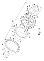
- FIG. 7 is an exploded perspective view of the acetabular hip implant of FIG. 6 ;
- FIG. 8 is an exploded perspective view of a fourth embodiment of an acetabular hip implant.
- Terms representing anatomical references such as anterior, posterior, medial, lateral, superior, inferior, etcetera, may be used throughout this disclosure in reference to both the orthopaedic implants described herein and a patient's natural anatomy. Such terms have well-understood meanings in both the study of anatomy and the field of orthopaedics. Use of such anatomical reference terms in the specification and claims is intended to be consistent with their well-understood meanings unless noted otherwise.
- the acetabular hip implant 20 generally includes an acetabular shell component 26 , a metal insert 28 , a polymer insert 30 , and a femoral head component 32 .
- the acetabular shell component 26 is generally configured to be implanted within the acetabulum 22 of a patient, as seen in FIG. 1 .
- the metal insert 28 is configured to be received within and secured to the acetabular shell component 26
- the polymer insert 30 is configured to be received within and secured to the metal insert 28
- the femoral head component 32 is configured to be received within and secured to the polymer insert 30 , as will be described in greater detail hereinafter.
- the femoral head component 32 is configured to be secured to a femoral stem 36 , which is configured to be implanted in femoral bone tissue (not shown) of the patient.
- the acetabular shell component 26 includes an outer surface 50 having a generally rounded shape that is hemispherical or at least partially spherical.
- the outer surface 50 is configured to be implanted within the acetabulum 22 using any method or structure known in the art.
- the acetabular shell component 26 further includes an inner surface 52 that is partially spherical in shape.
- a protrusion 70 is formed within or otherwise attached to the inner surface 52 of the acetabular shell component 26 .
- the protrusion 70 in this embodiment is an outwardly extending projection that cooperates with a feature within the metal insert 28 to allow rotation of the metal insert 28 with respect to the acetabular shell component 26 about an axial axis 72 , as will be discussed in greater detail below.
- the metal insert 28 includes an outer surface 80 having a generally hemispherical or at least partially spherical shape and having a size that is slightly smaller than a size of the inner surface 52 of the acetabular shell component 26 .
- the outer surface 80 of the metal insert 28 is configured to be received and secured within a cavity 58 formed by the inner surface 52 of the acetabular shell component 26 .
- a recess 82 is formed within the outer surface 80 of the metal insert 28 (as seen in FIG.
- the recess 82 cooperates with the protrusion 70 in the inner surface 52 of the acetabular shell component 26 to allow the metal insert 28 to rotate relative to the acetabular shell component 26 about the axial axis 72 .
- the acetabular shell component 26 is shown having an outwardly extending element (protrusion 70 ) and the metal insert 28 is shown having an inwardly extending element (recess 82 ), such elements may be reversed and/or other elements that cooperate to allow rotation of the metal insert 28 relative to the acetabular shell component 26 about the axial axis 72 may be utilized.
- the protrusion 70 and recess 82 cooperate to prevent rotation of the metal insert 28 with respect to the acetabular shell component 26 about any other axes, including an abduction axis 90 and a flexion axis 92 .
- the axial axis 72 in the embodiments shown herein, is orthogonal to the abduction axis 90 and the flexion axis 92
- the abduction axis 90 is orthogonal to the flexion axis 92 .
- the metal insert 28 further includes an inner surface 100 that is generally partially spherical in shape.
- a set of opposing flats 102 , 104 is defined in the inner surface 100 on opposing sides 106 , 108 , respectively, of the metal insert 28 .
- the opposing flats 102 , 104 are discrete in that they are separate and isolated from one another.
- the flats 102 , 104 are diametrically opposite one another and defined in the inner surface 100 on opposing sides 106 , 108 of the insert 28 .
- the flats 102 , 104 in this embodiment, are generally perpendicular to the abduction axis 90 .
- the flats 102 , 104 are also parallel to each other.
- Each flat 102 , 104 is at least partially circular, for example semi-circular, in shape, wherein midpoints of non-circular edges of the flats 102 , 104 define the abduction axis 90 .
- the function of the flats 102 , 104 will be described in greater detail below.
- the polymer insert 30 includes an outer surface 120 having a generally hemispherical or at least partially spherical shape and having a size that is slightly smaller than a size of a cavity 122 formed by the inner surface 100 of the metal insert 28 .
- the outer surface 120 of the polymer insert 30 is configured to be received and secured within the cavity 122 .
- the outer surface 120 of the polymer insert 30 further includes a set of opposing flats 124 , 126 defined in opposing sides 128 , 130 , respectively, of the outer surface 120 of the polymer insert 30 .
- the opposing flats 124 , 126 are discrete in that they are separate and isolated from one another.
- the flats 124 , 126 are diametrically opposite one another and defined in the outer surface 120 on opposing sides 128 , 130 of the insert 30 .
- the flats 124 , 126 are generally perpendicular to the abduction axis 90 .
- Each flat 124 , 126 is at least partially circular, for example semi-circular, in shape, wherein midpoints of non-circular edges of the flats 124 , 126 define the abduction axis 90 .
- the flats 124 , 126 are also generally parallel to each other and generally parallel to the metal insert's flats 102 , 104 .
- the flats 124 , 126 of the polymer insert 30 are in contact with the flats 102 , 104 of the metal insert 28 , respectively.
- the polymer insert 30 will only fit within the metal insert 28 with the polymer insert's flats 124 , 126 in contact with the metal insert's flats 102 , 104 in such a manner.
- the flats 102 , 104 create a bearing surface that allow the polymer insert 30 to rotate relative to the metal insert 28 about the abduction axis 90 . This arrangement also prevents rotation of the polymer insert 30 relative to the metal insert 28 about any other axis, including about the axial axis 72 and the flexion axis 92 .
- the polymer insert 30 further includes an inner surface 140 that is generally partially spherical in shape.
- a set of opposing flats 142 , 144 is defined within the inner surface 140 on opposing sides 146 , 148 , respectively, of the polymer insert 30 .
- the opposing flats 142 , 144 are discrete in that they are separate and isolated from one another.
- the flats 142 , 144 are diametrically opposite one another and defined in the inner surface 140 on opposing sides 146 , 148 of the insert 30 .
- the opposing flats 142 , 144 in this embodiment, are generally perpendicular to the flexion axis 92 .
- the opposing flats 142 , 144 are also parallel to each other.
- Each flat 142 , 144 is at least partially circular, for example semi-circular, in shape, wherein midpoints of non-circular edges of the flats 142 , 144 define the flexion axis 92 .
- the function of the opposing flats 142 , 144 will be described in greater detail hereinafter.
- the femoral head component 32 includes an outer surface 160 having a generally spherical shape and having a size that is slightly smaller than the size of a cavity formed by the inner surface 140 of the polymer insert 30 .
- the femoral head component 32 is configured to be received by and secured within the cavity formed by the inner surface 140 of the polymer insert 30 .
- the outer surface 160 of the femoral head component 32 further includes a set of opposing flats 164 , 166 on opposing sides 168 , 170 of the femoral head component 32 .
- the opposing flats 164 , 166 are discrete in that they are separate and isolated from one another.
- the flats 164 , 166 are diametrically opposite one another and defined in the outer surface 160 on opposing sides 168 , 170 of the femoral head component 32 .
- the opposing flats 164 , 166 are generally perpendicular to the flexion axis 92 .
- Each flat 164 , 166 is at least partially circular, for example semi-circular or a circular, in shape.
- the flats 164 , 166 are circular and centerpoints of the flats 164 , 166 define the flexion axis 92 .
- the opposing flats 164 , 166 are also generally parallel to each other and generally parallel to the opposing flats 142 , 144 of the polymer insert 30 .
- the flats 142 , 144 of the polymer insert 30 and the flats 164 , 166 of the femoral head component 32 are also orthogonal to the flats 102 , 104 of the metal insert 28 and the flats 124 , 126 of the polymer insert 30 .
- the opposing flats 164 , 166 of the femoral head component 32 are positioned in contact with the opposing flats 142 , 144 of the polymer insert 30 , respectively.
- the femoral head component 32 will only fit within the polymer insert 30 with the opposing flats 164 , 166 of the femoral head component 32 positioned in contact with the opposing flats 142 , 144 of the polymer insert 30 , respectively.
- the opposing flats 142 , 144 creates a bearing surface that allows the femoral head component 32 to rotate with respect to the polymer insert 30 about the flexion axis 92 . This arrangement also prevents rotation of the femoral head component 32 with respect to the polymer insert 30 about any other axis, including about the axial axis 72 and the abduction axis 90 .
- FIGS. 4 and 5 depict an alternative embodiment of an acetabular hip implant 220 .
- the acetabular hip implant 220 is similar to the acetabular hip implant of FIGS. 1 and 2 and, thus, only the differences will be described.
- the protrusion 70 has been replaced by an aperture 222 and the recess 82 has been replaced by a projection 224 .
- the aperture 222 is formed by an outwardly extending generally cylindrical wall 226 and the projection 224 is formed by an outwardly extending generally cylindrical wall 228 having a diameter slightly less than the diameter of the aperture 222 .
- the projection 224 fits and is retained within the aperture 222 .
- such an arrangement allows rotation of the metal insert 28 relative to the acetabular shell component 26 about the axial axis 72 , but prevents rotation about any other axes, including the abduction axis 90 and the flexion axis 92 .
- the cylindrical walls 226 , 228 may take other forms.
- the acetabular hip implant 220 includes an additional constraint that aids in retaining the femoral head component 32 within the polymer insert 30 .
- the polymer insert 30 includes a plurality of extensions 230 that are integral with and extend outwardly from the polymer insert 30 .
- the extension 230 are generally spherical in shape and extend outwardly beyond outermost ends of the acetabular shell component 26 and the metal insert 28 .
- the extensions 230 form opposing V-shaped openings 232 , which are formed by generally straight edges 234 , and opposing C-shaped openings 236 .
- the distance D 1 between opposing extensions 230 is less than an inner diameter D 2 of the polymer insert 30 and a diameter D 3 of the femoral head component 32 . Therefore, the extensions 230 aid in retaining the femoral head component 32 within the polymer insert 30 .
- the V-shaped openings 232 and the C-shaped openings 236 provide some resilience and flexibility to the extensions 230 to allow the femoral head component 34 to be inserted into the polymer insert 30 when enough force is exerted, while providing resistance to dislocation of the femoral head component 34 from the polymer insert 30 .
- the acetabular shell component 26 is modular.
- the acetabular shell component 26 includes a polymer component 322 and a metal component 324 , wherein the polymer component 322 is retained within and secured to the metal component 324 .
- the acetabular shell component 26 of FIGS. 6 and 7 also includes an aperture 340 formed through the acetabular shell component 26 .
- the cylindrical wall 228 and a cylindrical wall 342 extending from the polymer component 322 extend through the aperture 340 and an inner surface of the cylindrical wall 342 forms a bearing surface against which the cylindrical wall 228 bears to allow the metal insert 28 to rotate with respect to the axial axis 72 .
- the polymer insert 30 includes opposing extensions 422 , 424 that are spherical in shape and follow the curvature of the polymer insert 30 . Similar to the extensions 230 of the embodiment of FIGS. 6 and 7 , a distance D 4 between the extensions 422 , 424 is less than an inner diameter D 5 of the polymer insert 30 and a diameter D 6 of the femoral head component 32 .
- the extensions 422 , 424 are resilient enough to allow the femoral head to be inserted into the polymer insert 30 when enough force is exerted, yet provide resistance to dislocation of the femoral head component 32 from the polymer insert 30 .
- the acetabular shell component 26 of any of the acetabular hip implants disclosed herein may be formed of any combination of metal, ultra-high molecular weight polyethylene (UHMWPE), ceramic, polyetheretherketone (PEEK), or any other materials known in the art.
- the acetabular shell component 26 includes a metal shell having an inner surface lined with a polymeric material (or a separate polymeric component attached to the metal shell, as in FIGS. 6 and 7 ).
- the polymeric material may be an ultra-high molecular weight polyethylene (UHMWPE) and the metal may be a higher hardness alloy, such as an alloy of cobalt and chromium, for example CoCrMo.
- the acetabular shell component 26 has a metal shell with an external surface that is provided with a coating that promotes ingrowth of bone tissue.
- the external surface of the metal shell may have a porous structure, for example, a coating of cobalt-chromium alloy beads, such as a product sold by DePuy Orthopaedics Inc, under the trade mark POROCOAT®.
- the external surface of the metal shell may be provided with a coating of an additional or alternative material that promotes bone ingrowth, such as a hydroxyapatite material.
- the metal and polymer inserts 28 , 30 and the femoral head component 32 may be formed of a ceramic, polymeric, metallic, PEEK, or any other material known in the art or as described herein, or combinations thereof.
- the components 26 , 28 , 30 , 32 of the acetabular hip implant 20 may have alternating materials, such that no two adjacent components are made of the same material.
- the alternating materials alternate between hard and polymeric materials.
- hard materials are metal, ceramic, or PEEK and an example of a polymeric material is UHMWPE.
- Different types of hard and polymeric materials may be utilized (e.g., for example, different metals may be used for the hard components or a metal may be used for one hard component and ceramic for another).
- the acetabular shell component 26 includes a metal shell having an inner surface lined with a polymeric material, the metal insert is made of a metallic material, the polymer insert is made of a polymeric material, and the femoral component is made of a metallic material.
- the acetabular shell component 26 includes is a metal monoblock, the insert adjacent the shell component 26 is made of a polymeric material, the other insert is made of a metallic material, and the femoral component is made of a polymeric material.
- the axes 72 , 90 , 92 are described as aligning with the anatomical axes (i.e., axial, abduction, and flexion), the axes 72 , 90 , 92 may alternatively be aligned in another manner, so long as the axes 72 , 90 , 92 are orthogonal to one another.
- the acetabular hip implants disclosed herein allow the three basic motions of the hip to be broken down into three different movements.
- the combined rotational capabilities of these three different movements namely, movement of the metal insert 28 with respect to the shell 26 about the axial axis 72 , movement of the polymer insert 30 with respect to the metal insert 28 about the abduction axis 90 , and movement of the femoral head component 32 with respect to the polymer insert 30 about the flexion axis 92 , provide a large range of motion of the femoral head component 32 relative to the acetabular shell component 26 .
- two liners 28 , 30 are depicted in the figures herein, it should be understood that a single liner 28 or 30 may be utilized.
- a projection and aperture or other similar features are shown as allowing, rotation about the axial axis and sets of flats are shown as allowing rotation about the abduction and flexion axes
- the projection and aperture could alternatively be utilized for rotation about the abduction axis or the flexion axis and the sets of flats may be utilized for rotation about the axial axis.
- the projection and the aperture of the shell 26 and the liner 28 would be switched with the flats of the liners 28 , 30 or with the flats of the liner 30 and the femoral head component 32 .
- each of the opposing sets of flats are depicted as having two parallel flats, each set of flats may alternatively be replaced by a single flat.
- the acetabular implant 20 is used in a total hip replacement procedure.
- a surgical method for implanting the acetabular hip implant 20 of FIGS. 1 and 2 involves assembling the components 26 , 28 , 30 , and 32 of the acetabular hip implant 20 and implanting the acetabular hip implant 20 within the acetabulum 22 of the patient while supporting the femoral stem 36 within the femoral bone tissue.
- a reamer is typically used to ream or otherwise cut the acetabulum 22 in order to form a hemispherically shaped cavity.
- the surgeon may then implant either final components or trial fit components.
- Trial fitting is well known in the art and assists the surgeon in final preparation of the acetabulum and in choosing the proper sizes of the various components of the acetabular hip implant 20 .
- the trial implant is removed and the surgeon may then implant the acetabular shell component 26 into the acetabulum 22 .
- the acetabular shell component 26 may be press fit, bolted, cemented or otherwise attached to the acetabulum 22 , as is well known in the art.
- the acetabular shell component 26 is implanted into the acetabulum 22 separately and then the metal insert 28 is pressed into the acetabular shell component 26 in vivo.
- the metal insert 28 is aligned with the acetabular shell component 26 such that the protrusion 70 of the acetabular shell component 26 is received within the recess 82 of the metal insert 28 to allow rotation of the metal insert 28 with respect to the acetabular shell component 26 about the axial axis 72 .
- the acetabular shell component 26 is therefore stationary and the metal insert 28 rotates about the axial axis 72 .
- the polymer insert 30 is pressed into the metal insert 28 in vivo.
- the polymer insert 30 may be pressed into the metal insert 28 external to the acetabulum 22 .
- the polymer insert 30 is aligned with the metal insert 28 such that the opposing flats 124 , 126 of the polymer insert 30 are in contact with the opposing flats 102 , 104 of the metal insert 28 .
- the positioning and shape of the opposing flats 102 , 104 and the opposing flats 124 , 126 allow the polymer insert 30 to rotate with respect to the metal insert 28 about the abduction axis 90 .
- the metal insert 28 is therefore stationary with respect to the abduction axis 90 .
- the surgeon secures the femoral head component 32 within the polymer insert 30 .
- the femoral stem 36 may already be implanted within the femoral bone tissue or may be implanted within the femoral bone tissue after the femoral head component 32 is secured within the polymer insert 30 .
- the femoral head component 32 is pressed into the polymer insert 30 with the opposing flats 164 , 166 of the femoral head component 32 positioned in contact with the opposing flats 142 , 144 of the polymer insert 30 , respectively.
- the positioning and shape of the opposing flats 142 , 144 and the opposing flats 164 , 166 allow the femoral head component 32 to rotate with respect to the polymer insert 30 about the flexion axis 92 .
- the polymer insert 30 is therefore stationary with respect to the flexion axis 92 .
- the components of the acetabular hip implant 20 are assembled in vivo.
- any of the components (or all) may instead be assembled external to the acetabulum 22 prior to implantation.
- one skilled in the art should understand that the same steps may be utilized (minus insertion of the polymer insert 30 into the metal insert 28 ) if the polymer insert 30 is omitted.
Abstract
Description
Claims (29)
Priority Applications (6)
| Application Number | Priority Date | Filing Date | Title |
|---|---|---|---|
| US13/435,514 US8771366B2 (en) | 2012-03-30 | 2012-03-30 | Mobile bearing hip assembly having decoupled motion along multiple axes |
| EP17195335.9A EP3308746B1 (en) | 2012-03-30 | 2013-03-20 | Mobile bearing hip assembly having decoupled motion along multiple axes |
| EP13714463.0A EP2830538B1 (en) | 2012-03-30 | 2013-03-20 | Mobile bearing hip assembly having decoupled motion along multiple axes |
| PCT/US2013/033117 WO2013148434A1 (en) | 2012-03-30 | 2013-03-20 | Mobile bearing hip assembly having decoupled motion along multiple axes |
| US14/314,809 US9066803B2 (en) | 2012-03-30 | 2014-06-25 | Method for performing an orthopaedic procedure |
| US14/722,946 US9393122B2 (en) | 2012-03-30 | 2015-05-27 | Mobile bearing hip assembly and method of performing an orthopaedic surgical procedure |
Applications Claiming Priority (1)
| Application Number | Priority Date | Filing Date | Title |
|---|---|---|---|
| US13/435,514 US8771366B2 (en) | 2012-03-30 | 2012-03-30 | Mobile bearing hip assembly having decoupled motion along multiple axes |
Related Child Applications (1)
| Application Number | Title | Priority Date | Filing Date |
|---|---|---|---|
| US14/314,809 Continuation US9066803B2 (en) | 2012-03-30 | 2014-06-25 | Method for performing an orthopaedic procedure |
Publications (2)
| Publication Number | Publication Date |
|---|---|
| US20130261761A1 US20130261761A1 (en) | 2013-10-03 |
| US8771366B2 true US8771366B2 (en) | 2014-07-08 |
Family
ID=48048263
Family Applications (3)
| Application Number | Title | Priority Date | Filing Date |
|---|---|---|---|
| US13/435,514 Active 2032-06-19 US8771366B2 (en) | 2012-03-30 | 2012-03-30 | Mobile bearing hip assembly having decoupled motion along multiple axes |
| US14/314,809 Active US9066803B2 (en) | 2012-03-30 | 2014-06-25 | Method for performing an orthopaedic procedure |
| US14/722,946 Active US9393122B2 (en) | 2012-03-30 | 2015-05-27 | Mobile bearing hip assembly and method of performing an orthopaedic surgical procedure |
Family Applications After (2)
| Application Number | Title | Priority Date | Filing Date |
|---|---|---|---|
| US14/314,809 Active US9066803B2 (en) | 2012-03-30 | 2014-06-25 | Method for performing an orthopaedic procedure |
| US14/722,946 Active US9393122B2 (en) | 2012-03-30 | 2015-05-27 | Mobile bearing hip assembly and method of performing an orthopaedic surgical procedure |
Country Status (3)
| Country | Link |
|---|---|
| US (3) | US8771366B2 (en) |
| EP (2) | EP3308746B1 (en) |
| WO (1) | WO2013148434A1 (en) |
Cited By (4)
| Publication number | Priority date | Publication date | Assignee | Title |
|---|---|---|---|---|
| US20150305872A1 (en) * | 2011-02-24 | 2015-10-29 | Depuy (Ireland) | Maintaining proper mechanics tha |
| US20160135958A1 (en) * | 2012-06-21 | 2016-05-19 | DePuy Synthes Products, Inc. | Constrained mobile bearing hip assembly |
| US20180028322A1 (en) * | 2016-07-28 | 2018-02-01 | Corentec Co., Ltd | Dual mobility acetabular cup assembly for artificial hip joint |
| US10420649B2 (en) * | 2015-04-15 | 2019-09-24 | 41 Hemiverse AG | Artificial joint implant |
Families Citing this family (12)
| Publication number | Priority date | Publication date | Assignee | Title |
|---|---|---|---|---|
| US20150025647A1 (en) * | 2013-07-16 | 2015-01-22 | Howmedica Osteonics Corp. | Dual mobility hip replacement system |
| CN104546227A (en) * | 2015-01-07 | 2015-04-29 | 北京爱康宜诚医疗器材股份有限公司 | Assembled double-acting acetabulum implant |
| CN105030376B (en) * | 2015-02-10 | 2017-02-01 | 江苏奥康尼医疗科技发展有限公司 | Total hip surface replacement implant |
| CN105030378B (en) * | 2015-05-15 | 2017-11-03 | 江苏奥康尼医疗科技发展有限公司 | A kind of high-molecular organic material semi-artificial hip joint prosthese |
| CN105078617A (en) * | 2015-08-04 | 2015-11-25 | 江苏奥康尼医疗科技发展有限公司 | Artificial hip joint acetabular cup |
| ES2563877B1 (en) * | 2015-12-31 | 2016-12-27 | Carlos González Bravo | Joint hip prosthesis with reduced effort and anteversion angle in the femoral head |
| AU2018200701B2 (en) | 2017-02-02 | 2023-07-27 | Howmedica Osteonics Corp. | Constrained shell for modular dual mobility system |
| US11583405B2 (en) | 2017-03-13 | 2023-02-21 | Floyd G. Goodman | Hard substance multi-hooded enarthrodial joint implant |
| US10849759B2 (en) * | 2017-03-13 | 2020-12-01 | Floyd G. Goodman | Ceramic multi-hooded enarthrodial joint implant |
| US11224517B2 (en) * | 2019-06-26 | 2022-01-18 | DePuy Synthes Products, Inc. | Mechanically coupled revision hip system and method |
| GB2585049A (en) * | 2019-06-26 | 2020-12-30 | L Univ Ta Malta | A prosthetic implant |
| DE102020210033A1 (en) * | 2020-08-07 | 2022-02-10 | Aesculap Ag | ball joint prosthesis |
Citations (5)
| Publication number | Priority date | Publication date | Assignee | Title |
|---|---|---|---|---|
| FR2357235A1 (en) | 1976-07-05 | 1978-02-03 | Leveau Henri | Artificial hip rolling bearing joint - has articulation on three axes by gimballed ball or roller bearings in spherical housing |
| EP0867158A2 (en) | 1997-03-26 | 1998-09-30 | Johnson & Johnson Professional, Inc. | Bipolar acetabular cup |
| US5888207A (en) | 1996-05-25 | 1999-03-30 | Gmt Gesellschaft Fur Medizinische Technik Mbh | Saddle-type hip prosthesis |
| US20040193282A1 (en) | 2003-03-31 | 2004-09-30 | Hanes Mark D. | Reduced wear orthopaedic implant apparatus and method |
| US20090192610A1 (en) * | 2008-01-30 | 2009-07-30 | Zimmer, Inc. | Orthopedic component of low stiffness |
Family Cites Families (4)
| Publication number | Priority date | Publication date | Assignee | Title |
|---|---|---|---|---|
| JP3161818B2 (en) * | 1992-06-15 | 2001-04-25 | ヤンマーディーゼル株式会社 | Joint prosthesis and method of assembling the same |
| US7115145B2 (en) * | 2003-07-03 | 2006-10-03 | Zimmer, Inc. | Acetabular component |
| DE102007031667A1 (en) * | 2006-08-04 | 2008-02-14 | Ceramtec Ag Innovative Ceramic Engineering | Insertion of vibration-damping elements in prosthetic systems for manipulation and damping of natural frequencies |
| US8858645B2 (en) * | 2012-06-21 | 2014-10-14 | DePuy Synthes Products, LLC | Constrained mobile bearing hip assembly |
-
2012
- 2012-03-30 US US13/435,514 patent/US8771366B2/en active Active
-
2013
- 2013-03-20 EP EP17195335.9A patent/EP3308746B1/en active Active
- 2013-03-20 WO PCT/US2013/033117 patent/WO2013148434A1/en active Application Filing
- 2013-03-20 EP EP13714463.0A patent/EP2830538B1/en not_active Not-in-force
-
2014
- 2014-06-25 US US14/314,809 patent/US9066803B2/en active Active
-
2015
- 2015-05-27 US US14/722,946 patent/US9393122B2/en active Active
Patent Citations (6)
| Publication number | Priority date | Publication date | Assignee | Title |
|---|---|---|---|---|
| FR2357235A1 (en) | 1976-07-05 | 1978-02-03 | Leveau Henri | Artificial hip rolling bearing joint - has articulation on three axes by gimballed ball or roller bearings in spherical housing |
| US5888207A (en) | 1996-05-25 | 1999-03-30 | Gmt Gesellschaft Fur Medizinische Technik Mbh | Saddle-type hip prosthesis |
| EP0867158A2 (en) | 1997-03-26 | 1998-09-30 | Johnson & Johnson Professional, Inc. | Bipolar acetabular cup |
| US20040193282A1 (en) | 2003-03-31 | 2004-09-30 | Hanes Mark D. | Reduced wear orthopaedic implant apparatus and method |
| US7108720B2 (en) | 2003-03-31 | 2006-09-19 | Depuy Products, Inc. | Reduced wear orthopaedic implant apparatus and method |
| US20090192610A1 (en) * | 2008-01-30 | 2009-07-30 | Zimmer, Inc. | Orthopedic component of low stiffness |
Non-Patent Citations (1)
| Title |
|---|
| Patent Cooperation Treaty International Search Report, International Application No. PCT/US2013/033117, Jul. 1, 2013, 5 pages. |
Cited By (9)
| Publication number | Priority date | Publication date | Assignee | Title |
|---|---|---|---|---|
| US20150305872A1 (en) * | 2011-02-24 | 2015-10-29 | Depuy (Ireland) | Maintaining proper mechanics tha |
| US10064729B2 (en) | 2011-02-24 | 2018-09-04 | Depuy Ireland Unlimited Company | Methods for maintaining proper mechanics THA |
| US20160135958A1 (en) * | 2012-06-21 | 2016-05-19 | DePuy Synthes Products, Inc. | Constrained mobile bearing hip assembly |
| US9700416B2 (en) * | 2012-06-21 | 2017-07-11 | DePuy Synthes Products, Inc. | Constrained mobile bearing hip assembly |
| US10314711B2 (en) | 2012-06-21 | 2019-06-11 | DePuy Synthes Products, Inc. | Constrained mobile bearing hip assembly and method |
| US11076960B2 (en) | 2012-06-21 | 2021-08-03 | DePuy Synthes Products, Inc. | Constrained mobile bearing hip assembly and method |
| US10420649B2 (en) * | 2015-04-15 | 2019-09-24 | 41 Hemiverse AG | Artificial joint implant |
| US20180028322A1 (en) * | 2016-07-28 | 2018-02-01 | Corentec Co., Ltd | Dual mobility acetabular cup assembly for artificial hip joint |
| US10729550B2 (en) * | 2016-07-28 | 2020-08-04 | Corentec Co., Ltd | Dual mobility acetabular cup assembly for artificial hip joint |
Also Published As
| Publication number | Publication date |
|---|---|
| US9066803B2 (en) | 2015-06-30 |
| EP2830538B1 (en) | 2017-12-06 |
| US20140309748A1 (en) | 2014-10-16 |
| US20150250596A1 (en) | 2015-09-10 |
| WO2013148434A1 (en) | 2013-10-03 |
| US9393122B2 (en) | 2016-07-19 |
| EP3308746A2 (en) | 2018-04-18 |
| EP2830538A1 (en) | 2015-02-04 |
| US20130261761A1 (en) | 2013-10-03 |
| EP3308746B1 (en) | 2019-04-24 |
| EP3308746A3 (en) | 2018-05-30 |
Similar Documents
| Publication | Publication Date | Title |
|---|---|---|
| US11076960B2 (en) | Constrained mobile bearing hip assembly and method | |
| US8771366B2 (en) | Mobile bearing hip assembly having decoupled motion along multiple axes | |
| US8845743B2 (en) | Interlocking reverse shoulder prosthesis method | |
| JP5706395B2 (en) | System for placing an acetabular cup in the acetabulum | |
| JP2022515289A (en) | Orthopedic prosthesis and method of acetabulum | |
| US11224517B2 (en) | Mechanically coupled revision hip system and method |
Legal Events
| Date | Code | Title | Description |
|---|---|---|---|
| AS | Assignment |
Owner name: DEPUY PRODUCTS, INC., INDIANA Free format text: ASSIGNMENT OF ASSIGNORS INTEREST;ASSIGNORS:WHITAKER, DUSTIN R.;RENDER, TODD D.;DRESSLER, MATTHEW R.;REEL/FRAME:028381/0134 Effective date: 20120507 |
|
| AS | Assignment |
Owner name: DEPUY SPINE, LLC, MASSACHUSETTS Free format text: ASSIGNMENT OF ASSIGNORS INTEREST;ASSIGNOR:DEPUY PRODUCTS, INC.;REEL/FRAME:030679/0948 Effective date: 20121230 Owner name: DEPUY SYNTHES PRODUCTS, LLC, MASSACHUSETTS Free format text: CHANGE OF NAME;ASSIGNOR:HAND INNOVATIONS LLC;REEL/FRAME:030680/0913 Effective date: 20121231 |
|
| AS | Assignment |
Owner name: HAND INNOVATIONS LLC, FLORIDA Free format text: ASSIGNMENT OF ASSIGNORS INTEREST;ASSIGNOR:DEPUY SPINE, LLC;REEL/FRAME:032967/0731 Effective date: 20121230 |
|
| STCF | Information on status: patent grant |
Free format text: PATENTED CASE |
|
| AS | Assignment |
Owner name: DEPUY SYNTHES PRODUCTS, INC., MASSACHUSETTS Free format text: CHANGE OF NAME;ASSIGNOR:DEPUY SYNTHES PRODUCTS, LLC;REEL/FRAME:034905/0851 Effective date: 20141219 |
|
| MAFP | Maintenance fee payment |
Free format text: PAYMENT OF MAINTENANCE FEE, 4TH YEAR, LARGE ENTITY (ORIGINAL EVENT CODE: M1551) Year of fee payment: 4 |
|
| MAFP | Maintenance fee payment |
Free format text: PAYMENT OF MAINTENANCE FEE, 8TH YEAR, LARGE ENTITY (ORIGINAL EVENT CODE: M1552); ENTITY STATUS OF PATENT OWNER: LARGE ENTITY Year of fee payment: 8 |