US8773967B2 - Method and system for transmitting signals between a first signal source and a second signal source - Google Patents
Method and system for transmitting signals between a first signal source and a second signal source Download PDFInfo
- Publication number
- US8773967B2 US8773967B2 US13/426,639 US201213426639A US8773967B2 US 8773967 B2 US8773967 B2 US 8773967B2 US 201213426639 A US201213426639 A US 201213426639A US 8773967 B2 US8773967 B2 US 8773967B2
- Authority
- US
- United States
- Prior art keywords
- signal
- time slot
- signals
- network
- signal source
- Prior art date
- Legal status (The legal status is an assumption and is not a legal conclusion. Google has not performed a legal analysis and makes no representation as to the accuracy of the status listed.)
- Expired - Fee Related, expires
Links
Images


Classifications
-
- H—ELECTRICITY
- H04—ELECTRIC COMMUNICATION TECHNIQUE
- H04B—TRANSMISSION
- H04B7/00—Radio transmission systems, i.e. using radiation field
- H04B7/14—Relay systems
- H04B7/15—Active relay systems
- H04B7/155—Ground-based stations
- H04B7/15521—Ground-based stations combining by calculations packets received from different stations before transmitting the combined packets as part of network coding
-
- H—ELECTRICITY
- H04—ELECTRIC COMMUNICATION TECHNIQUE
- H04B—TRANSMISSION
- H04B7/00—Radio transmission systems, i.e. using radiation field
- H04B7/02—Diversity systems; Multi-antenna system, i.e. transmission or reception using multiple antennas
- H04B7/04—Diversity systems; Multi-antenna system, i.e. transmission or reception using multiple antennas using two or more spaced independent antennas
- H04B7/0413—MIMO systems
-
- H—ELECTRICITY
- H04—ELECTRIC COMMUNICATION TECHNIQUE
- H04B—TRANSMISSION
- H04B7/00—Radio transmission systems, i.e. using radiation field
- H04B7/14—Relay systems
- H04B7/15—Active relay systems
- H04B7/155—Ground-based stations
-
- H—ELECTRICITY
- H04—ELECTRIC COMMUNICATION TECHNIQUE
- H04B—TRANSMISSION
- H04B7/00—Radio transmission systems, i.e. using radiation field
- H04B7/24—Radio transmission systems, i.e. using radiation field for communication between two or more posts
- H04B7/26—Radio transmission systems, i.e. using radiation field for communication between two or more posts at least one of which is mobile
- H04B7/2603—Arrangements for wireless physical layer control
- H04B7/2606—Arrangements for base station coverage control, e.g. by using relays in tunnels
-
- H—ELECTRICITY
- H04—ELECTRIC COMMUNICATION TECHNIQUE
- H04L—TRANSMISSION OF DIGITAL INFORMATION, e.g. TELEGRAPHIC COMMUNICATION
- H04L1/00—Arrangements for detecting or preventing errors in the information received
- H04L1/02—Arrangements for detecting or preventing errors in the information received by diversity reception
- H04L1/06—Arrangements for detecting or preventing errors in the information received by diversity reception using space diversity
- H04L1/0618—Space-time coding
-
- H—ELECTRICITY
- H04—ELECTRIC COMMUNICATION TECHNIQUE
- H04L—TRANSMISSION OF DIGITAL INFORMATION, e.g. TELEGRAPHIC COMMUNICATION
- H04L1/00—Arrangements for detecting or preventing errors in the information received
- H04L2001/0092—Error control systems characterised by the topology of the transmission link
- H04L2001/0097—Relays
-
- H—ELECTRICITY
- H04—ELECTRIC COMMUNICATION TECHNIQUE
- H04W—WIRELESS COMMUNICATION NETWORKS
- H04W88/00—Devices specially adapted for wireless communication networks, e.g. terminals, base stations or access point devices
- H04W88/02—Terminal devices
- H04W88/04—Terminal devices adapted for relaying to or from another terminal or user
Definitions
- the present invention is directed to the field of signal communication in a wireless network, especially the field of mobile communication systems. More specifically, the present invention relates to a method and a relay station for relaying signals between a first signal source and a second signal source, a method and a system for transmitting signals between a first signal source and a second signal source, and to a method and a signal source for receiving at the signal source a plurality of signals from a remote signal source.
- Network coding (see e.g. Ahlswede, R.; Cai, N.; Li, S.-Y. R.; Yeung, R. W.-H. (2000). Network information flow. IEEE Transactions on Information Theory, 46 (2000), pp. 1204-1216) is a data distribution approach based on store, code and forward. The core notion is to allow and encourage mixing of data at intermediate network nodes. It helps to exploit the potential of the broadcasting nature of wireless radio in improving throughput of wireless communication systems.
- MIMO multiple input multiple output
- the Alamouti scheme (see Alamouti, S. M.: A simple transmit diversity technique for wireless communication. IEEE Journal on Select Areas in Communications, vol. 16 (1998), pp. 1451-1458), for instance, may achieve full diversity with STBC (Space Time Block Coding).
- MIMO systems may also increase the data rate by using a spatial multiplexing scheme.
- a method for relaying signals between a first signal source and a second signal by a relay station that includes at least two antennas for receiving/transmitting signals from/to the first and second signal sources may have the steps of: in a first time slot, receiving at the relay station a first signal from the first source and a first signal from the second source; in a second time slot, receiving at the relay station a second signal from the first source and a second signal from the second source; at the relay station, generating a first network coded signal by network coding the first signals received from the first and second signal sources in the first time slot, and generating a second network coded signal by network coding the second signals received from the first and second signal sources in the second time slot; in a third time slot, transmitting the first network coded signal by a first antenna of the relay station, and transmitting the second network coded signal by a second antenna of the relay station; and in a fourth time slot, transmitting the first network coded signal by the second antenna of the relay server, and transmitting
- Another embodiment may have a computer readable medium including a plurality of instructions for carrying out a method of claim 1 , wherein executing the instructions by a computer.
- a relay station for relaying signals between a first signal source and a second signal source may have: at least two antennas for receiving/transmitting signals; and a processor is configured to cause network coding of signals received, the relay station being configured to cause: in a first time slot, receiving at the relay station a first signal from the first source and a first signal from the second source; in a second time slot, receiving at the relay station a second signal from the first source and a second signal from the second source; at the relay station, generating a first network coded signal by network coding the first signals received from the first and second signal sources in the first time slot, and generating a second network coded signal by network coding the second signals received from the first and second signal sources in the second time slot; in a third time slot, transmitting the first network coded signal by a first antenna of the relay station, and transmitting the second network coded signal by a second antenna of the relay station; and in a fourth time slot, transmitting the first network coded signal by the second antenna of
- a system may have: a first signal source; a second signal source; and a relay station for relaying signals between a first signal source and a second signal source, including: at least two antennas for receiving/transmitting signals; and a processor is configured to cause network coding of signals received, the relay station being configured to cause: in a first time slot, receiving at the relay station a first signal from the first source and a first signal from the second source; in a second time slot, receiving at the relay station a second signal from the first source and a second signal from the second source; at the relay station, generating a first network coded signal by network coding the first signals received from the first and second signal sources in the first time slot, and generating a second network coded signal by network coding the second signals received from the first and second signal sources in the second time slot; in a third time slot, transmitting the first network coded signal by a first antenna of the relay station, and transmitting the second network coded signal by a second antenna of the relay station; and in
- Embodiments of the invention provide a new two-step communication protocol combined with MIMO (Multiple Input Multiple Output) technologies, which allows improving the system throughput in cooperative networks.
- the protocol is termed MINEC (MEMO Network Coding).
- MINEC MIMO Network Coding
- a three nodes network with multi-antennas on a relay node is described as an illustrative example of MINEC.
- step one of MINEC the two source nodes transmit messages simultaneously; in step two, the relay node broadcasts coded data with network and space-time coding.
- a binary symmetric relay channel model may be used to carry out the theoretical performance analysis of MINEC.
- the theoretical findings are validated by Monte-Carlo-simulations. It is found that MINEC facilitates a performance equivalent to a 2 ⁇ 2 V-BLAST MIMO and a two 2 ⁇ 1 Alamouti MIMO in transmitting phase and forwarding phase, respectively
- FIG. 1 shows a three nodes relay network with two step transmission according to an embodiment of the invention
- FIG. 2 shows a flow diagram illustrating a method according to an embodiment of the invention for transmitting signals between to signal nodes in the three nodes relay network of FIG. 1 ;
- FIG. 3 shows a memoryless binary symmetric relay network channel in the three nodes relay network of FIG. 1 ;
- FIG. 4 shows a graph illustrating a comparison of the overall bit error performance obtained in the three nodes relay network of FIG. 1 ;
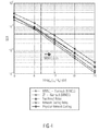
- FIG. 5 shows a graph illustrating the channel capacity as a function of the SNR in the three nodes relay network of FIG. 1 .
- FIG. 1 a three-nodes relay network as it is shown in FIG. 1 .
- the present invention naturally, is not limited to such a three-nodes relay network as shown in FIG. 1 , rather, the inventive approach, namely the new two-step communication protocol described subsequently in further detail, can be applied to any network in which a plurality of messages or signals are to be exchanged between a plurality of signal nodes which cannot directly communicate with each other, but communicate via a relay station.
- the network itself may comprise a plurality of relay nodes or relay stations and a plurality of signal nodes or signal sources communicating with each other, and in case such communication takes place via a relay node, the inventive two-step communication protocol may be used in a manner as described below.
- FIG. 1 shows an example of a three-nodes relay network comprising a first signal node S 1 .
- the signal node S 1 comprises an antenna ANT 1 and a signal processing unit 100 .
- the network further comprises a second signal node S 2 comprising an antenna ANT 2 and a central processing unit 200 .
- the network comprises a relay node R.
- the relay node R comprises a first antenna ANT R1 and a second antenna ANT R2 .
- the relay node R comprises a central processing unit or data processing unit 300 .
- the first signal node S 1 when sending towards the relay node R has a range that is shown by the dashed dotted line 102 .
- the second signal source S 2 when transmitting towards the relay node R has a range as shown by the dashed dotted line 202 . While the ranges of the signal nodes S 1 and S 2 overlap in the area where the relay node is provided, the second signal source S 2 is out of range of the first signal node S 1 and vice versa. Therefore, communication between the signal nodes S 1 and S 2 is done via the relay node R.
- Solid line arrows indicate a communication from the first and second signal nodes S 1 and S 2 towards the relay node during a first and a second time slot, more specifically during two consecutive time slots i, i+1.
- the dashed arrows indicate the communication from the relay node R to the signal nodes S 1 and S 2 at a third and a fourth time, for example, during time slots i+2 and i+3.
- FIG. 2 is a flow diagram on the basis of which the inventive system and the functionality thereof will be described, and for the description it is assumed that the transmission starts at a first time slot i at step S 100 .
- the first signal node or signal force S 1 and also the second signal source or second signal node S 2 transmits a first signal S i to the relay station R, as is indicated by the solid line arrows in FIG. 1 .
- These signals are received at the relay station or relay node R.
- second signals s i+1 are transmitted from the signal nodes S 1 and S 2 to the relay node R as is indicated again by the solid line arrows in FIG. 1 and as is shown in step S 102 of FIG. 2 .
- These signals are received at the relay node and at step S 104 .
- the signals received from the signal nodes S 1 and S 2 during the consecutive time slots i and i+1 are network coded, more specifically, a first network coded signal is generated on the basis of the first signals received from the signal nodes S 1 and S 2 , and a second network coded signal is generated on the basis of the second signals received at the relay node R, as shall be described in further detail below.
- the relay station R After completing the generation of the network coded signal, at a time slot i+2 the relay station R transmits the first and second network coded signals, as is shown at step S 106 . More specifically, the relay node R transmits the first network coded signal via its first antenna ANT R1 and the second network coded signal via its second antenna ANT R2 . These signals are received at the signal nodes S 1 and S 2 . In a following time slot, advantageously in time slot i+3, as is shown at step S 108 , the relay node R transmits again the first and second coded signals, however, in this time slot the relay node transmits the first network coded signal via its second antenna ANT R2 and the second network coded signal via its first antenna ANT R1 . Again, the transmitted network coded signals are received by the signal nodes S 1 and S 2 .
- step S 110 at the first and second signal nodes S 1 and S 2 the respective signals that originated from the other signal source are determined on the basis of the received first and second network coded signals and on the basis of the first and second signals that were originally sent out from the respective signal node to the relay station R.
- FIGS. 1 and 2 and also the subsequent description of the advantageous embodiments relate to networks including only two signal nodes and one relay node
- the present invention is not limited to such networks, rather various network configurations can be employed and the network may comprise a plurality of relay nodes and more than two signal nodes.
- a relay node may comprise more than two antennas, thereby allowing expanding the two-step communication protocol in accordance with the teachings of the present invention to a communication between more than two signal nodes within a network that uses the relay nodes for communicating with each other.
- the source nodes S 1 and S 2 are out of each other's communication range and have messages to exchange. They communicate through the relay node R that is within the range of both source nodes S 1 and S 2 . It is assumed that the transmission is organized in consecutive time slots enumerated by i, i ⁇ .
- the source nodes S 1 and S 2 each comprise a single transceiver antenna ANT 1 and ANT 2 .
- the inventive system comprises a relay node R having two transceiver antennas ANT R1 and ANT R2 , instead of having only a single transceiver antenna. Since the signals originating at source nodes S 1 and S 2 are mutually independent from each other and are locally displaced, and since the relay node R has the two transceiver antennas ANT R1 and ANT R2 , the system may be seen as a 2 ⁇ 2 spatial multiplexing MIMO system. In the case of the relay node R transmitting and the source nodes S 1 and S 2 receiving information, the system may be viewed as a two 2 ⁇ 1 MISO systems. Thus, the relay network of FIG. 1 benefits from a virtual MIMO concept, exploiting the simultaneous operation of all antennas of all nodes.
- a benefit from the network coding capabilities combined with MIMO is obtained by a two-step protocol for the MIMO relay system shown in FIG. 1 .
- the protocol is termed MINEC (MIMO Network Coding).
- MINEC MIMO Network Coding
- the source nodes S 1 and S 2 in FIG. 1 transmit data simultaneously.
- the signal transmitted by the source node S 1 in the i-th time slot is denoted by s i (1) (t) and the signal transmitted by the source node S 2 in the (i+1)-th time slot is denoted by s i+1 (1) (t).
- the signals transmitted by the source node S 2 in the i-th and the (i+1)-th time slots are denoted by s i (2) (t) and s i+1 (2) (t), respectively.
- the transmit signals s i (1) (t), s i+1 (1) (t), s i (2) (t) and s i+1 (2) (t) are binary phase shift keying (BPSK) modulated signals, each comprising N bits which are transmitted consecutively assuming a single carrier transmission.
- E b denotes the bit energy and T b is the bit duration.
- the transmit signals are hence given by
- the relay node R receives these signals via its two transceiver antennas ANT R1 and ANT R2 , h i (1,1) (t) denotes the channel impulse response between the first source node S 1 and the first antenna ANT R1 of the relay node R in the time slot i. h i (1,2) (t) denotes the channel impulse response between the first source node S 1 and the second antenna ANT R2 of the relay node R in the time slot i. Similarly, h i (2,1) (t) and h i (2,2) (t) represent the channel impulse responses between the second source node S 2 and the first antenna ANT R1 and the second antenna ANT R2 of the relay node R.
- the system which applies the inventive combination of network coding and MIMO, may be based on ad-hoc principles within a short range scenario with low transmit powers, exhibiting low mobility.
- the channel impulse responses approximately represent single path channels with negligible time variance; rather, inter-time slot time variations can occur.
- the general complex-valued numbers h i (1,1) , h i (1,2) , h i (2,1) , and h i (2,2) can be used to represent the channel impulse responses.
- h i (1,1) , h i (1,2) , h i (2,1) , and h i (2,2) represent i.i.d. Rayleigh-flat-fading channels with a variance ⁇ 2 equal to 1.
- Different detection techniques for example the zero-forcing (ZF) based V-BLAST (see e.g. Tse, D.; Viswanath, P.: Fundamentals of wireless communications. New York: Cambridge University Press, 2005) or its minimum mean squared error (MMSE) counterpart SIC-MMSE may be used.
- ZF zero-forcing
- V-BLAST see e.g. Tse, D.; Viswanath, P.: Fundamentals of wireless communications. New York: Cambridge University Press, 2005
- MMSE minimum mean squared error
- the decode-and-forward (DF) forwarding scheme (see e.g. Ahlswede, R.; Cai, N.; Li, S.-Y. R.; Yeung, R. W.-H. (2000). Network information flow. IEEE Transactions on Information Theory, 46 (2000), pp. 1204-1216 or Fitzek, F. H. P.; Katz, M. D. (Eds,): Cooperation in wireless networks: Principles and applications. Berlin: Springer, 2006) is deployed in the second step of MINEC.
- the relay node R re-encodes and re-modulates the received signals (see equation (6)) and forwards them to the source nodes S 1 and S 2 .
- STBC network coding and space-time block coding
- r i+2 (1) (t) and r i+2 (2) (t) represent the signals transmitted over the first antenna ANT R1 and the second antenna ANT R2 of the relay node R, respectively, in the time slot (i+2).
- the network coding scheme is given by the bit-wise multiplication of the signals received in the i-th and the (i+1)-th time slots according to the following rule
- r i+3 (1) (t) and r i+3 (2) (t) are the transmit signals in the time slot (i+3) which correspond to r i+2 (1) (t) and r i+2 (2) (t).
- S. M. A simple transmit diversity technique for wireless communication. WEE Journal on Select Areas in Communications, vol. 16 (1998), pp. 1451-1458, the signals
- the source nodes S 1 and S 2 detect ⁇ circumflex over (d) ⁇ i+2,n , n ⁇ 1 , . . . , N ⁇ , and ⁇ circumflex over (d) ⁇ i+3,n , n ⁇ 1 . . . , N ⁇ , each by combining the two successive incoming signals with corresponding channel information, and estimating the combined signal using the maximum likelihood (ML) decision rule (see e.g. Alamouti, S. M.: A simple transmit diversity technique for wireless communication. IEEE Journal on Select Areas in Communications, vol. 16 (1998), pp. 1451-1458).
- the corresponding bit error probability of this 2 ⁇ 1 MISO system is given by
- each source node After the detection which yields ⁇ circumflex over (d) ⁇ i+2,n , n ⁇ 1 , . . . , N ⁇ , and ⁇ circumflex over (d) ⁇ i+3,n , n ⁇ 1 , . . . , N ⁇ at the source nodes, each source node is able to determine the particular information that originated from the other source node.
- the first source node S 1 computes
- the second source S 2 transfers its information sequences b i (2) and b i+1 (2) to the first source node S 1 .
- the efficiency is still one information sequence per time slot, only the latency is four time slots.
- BSRNC binary symmetric relay network channel
- the input to the BSRNC consists of two bits, (b (1) ,b (2) ), having four possible realizations, ( ⁇ 1, ⁇ 1), ( ⁇ 1,+1), (+1, ⁇ 1) and (+1, +1).
- the transmission over the BSRNC is characterized by using error probabilities.
- p (1) is the probability of an error associated with the link between the source node S 1 and the relay node R that the transmitted bit b (1) is received correctly. Consequently, the correct reception occurs with a probability (1 ⁇ p (1) ).
- p (2) and (1 ⁇ p (2) ) denote the probability of an erroneous and error-free transmission between the source node S 2 and the relay node R for bit b (2) , respectively.
- the error probabilities p (1) and p (2) reflect the spatial multiplexing reception at the relay node B which are represented by equations (7) or (8) when the channel state information is perfectly known at the relay node R.
- the reception probabilities at the source nodes S 1 and S 2 in the second MINEC step are independent of each other. It is now assumed that the transmission from the relay node R to the source nodes S 1 and S 2 are erroneous with probabilities ⁇ tilde over (p) ⁇ (1) and ⁇ tilde over (p) ⁇ (2) , respectively.
- the error probabilities ⁇ tilde over (p) ⁇ (1) and ⁇ tilde over (p) ⁇ (2) at the source nodes S 1 and S 2 represent the STBC (Alamouti) reception with P e,Alam . of equation (15). After the reception, the following probabilities for the source node S 1 exist:
- I ⁇ ( b ; b ⁇ ) - ⁇ b ⁇ ⁇ B ⁇ ⁇ Pr ⁇ ⁇ b ⁇ ⁇ ⁇ log 2 ⁇ ( Pr ⁇ ⁇ b ⁇ ⁇ ) + ⁇ b ⁇ B ⁇ ⁇ Pr ⁇ ⁇ b ⁇ ⁇ ⁇ b ⁇ ⁇ B ⁇ ⁇ Pr ⁇ ⁇ b ⁇
- Pr ⁇ circumflex over (b) ⁇ is the probability of the occurrence of the output bits pair ⁇ circumflex over (b) ⁇
- b ⁇ is the probability of the observation of ⁇ circumflex over (b) ⁇ , given b.
- X 1 p ⁇ ( 1 ) + p ( 1 ) + p ( 2 ) - 2 ⁇ ⁇ p ( 1 ) ⁇ p ( 2 ) - 2 ⁇ ⁇ p ⁇ ( 1 ) ⁇ p ( 1 ) - 2 ⁇ ⁇ p ⁇ ( 1 ) ⁇ p ( 2 ) + 4 ⁇ ⁇ p ⁇ ( 1 ) ⁇ p ( 1 ) ⁇ p ( 2 ) , ( 26 )
- X 2 p ⁇ ( 2 ) + p ( 1 ) + p ( 2 ) - 2 ⁇ ⁇ p ( 1 ) ⁇ p ( 2 ) - 2 ⁇ ⁇ p ⁇ ( 2 ) ⁇ p ( 1 ) - 2 ⁇ ⁇ p ⁇ ( 2 ) + 4 ⁇ ⁇ p ⁇ ( 2 ) ⁇ p ( 1 ) ⁇ p ( 2 ) ,
- I ⁇ ( b ; b ⁇ ) - [ ( 1 - Y 1 ) ⁇ log 2 ⁇ ( 1 - Y 1 ) + Y 1 ⁇ log 2 ⁇ Y 1 + ( 1 - Y 2 ) ⁇ log 2 ⁇ ( 1 - Y 2 ) + Y 2 ⁇ log 2 ⁇ Y 2 ] + [ ( 1 - X 1 ) ⁇ log 2 ⁇ ( 1 - X 1 ) + X 1 ⁇ log 2 ⁇ X 1 + ( 1 - X 2 ) ⁇ log 2 ⁇ ( 1 - X 2 ) + X 2 ⁇ log 2 ⁇ X 2 ] . ( 30 )
- FIG. 4 provides a comparison of the overall bit error performance obtained in the three nodes relay network.
- the source node S 1 or S 2 applies an Alamouti Maximum Likelihood (ML) symbol detector followed by a binary exclusive OR operation to extract BPSK signals from the other.
- ML Alamouti Maximum Likelihood
- the MINEC scheme outperforms the traditional relay network scheme, the network coding relay scheme and the PNC.
- FIG. 5 illustrates the obtained channel capacity as a function of the SNR assuming that the SNR values in both MINEC steps are identical.
- the theoretical analysis results of equation (30) with corresponding receivers in both MINEC steps are also plotted which are aligned with Monte-Carlo simulation results of the channel capacity with MINEC scheme.
- the proposed MINEC scheme and the PNC see e.g. Zhang, S.; Liew, S.; Lam, P.: Hot topic: Physical layer network coding.
- MobiCom'06 Mobile Computing and Networking
- MINEC new combination of MIMO and network coding
- the benefits of MINEC come from the deployment of multi-antennas ANT R1 and ANT R2 at the relay node R.
- MINEC both the advantages of code multiplexing and spatial diversity gains are combined.
- aspects have been described in the context of an apparatus, it is clear that these aspects also represent a description of the corresponding method, where a block or device corresponds to a method step or a feature of a method step. Analogously, aspects described in the context of a method step also represent a description of a corresponding block or item or feature of a corresponding apparatus.
- embodiments of the invention can be implemented in hardware or in software.
- the implementation can be performed using a digital storage medium, for example a floppy disk, a DVD, a CD, a ROM, a PROM, an EPROM, an EEPROM or a FLASH memory, having electronically readable control signals stored thereon, which cooperate (or are capable of cooperating) with a programmable computer system such that the respective method is performed.
- a digital storage medium for example a floppy disk, a DVD, a CD, a ROM, a PROM, an EPROM, an EEPROM or a FLASH memory, having electronically readable control signals stored thereon, which cooperate (or are capable of cooperating) with a programmable computer system such that the respective method is performed.
- Some embodiments according to the invention comprise a data carrier having electronically readable control signals, which are capable of cooperating with a programmable computer system, such that one of the methods described herein is performed.
- embodiments of the invention can be implemented as a computer program product with a program code, the program code being operative for performing one of the methods when the computer program product runs on a computer.
- the program code may for example be stored on a machine readable carrier.
- Other embodiments comprise the computer program for performing one of the methods described herein, stored on a machine readable carrier.
- an embodiment of the inventive method may, therefore, be
- a further embodiment comprises a processing means, for example a computer, or a programmable logic device, configured to or adapted to perform one of the methods described herein.
- a further embodiment comprises a computer having installed thereon the computer program for performing one of the methods described herein.
- a programmable logic device for example a field programmable gate array
- a field programmable gate array may cooperate with a microprocessor in order to perform one of the methods described herein.
- the methods are advantageously performed by any hardware apparatus.
Abstract
Description
-
- Ahlswede, R.; Cal, N.; Li, S.-Y. R.; Yeung, R. W.-H. (2000). Network information flow. IEEE Transactions on Information Theory, 46 (2000), pp. 1204-1216,
- Zhang, S.; Liew, S.; Lam, P.: Hot topic: Physical layer network coding. In Proceedings of the 12th Annual International Conference on Mobile Computing and Networking (MobiCom'06), 2006, pp. 358-365,
- Katti, S.; Gollakota, S.; Katabi, D,: Embracing wireless interference: Analog network coding. Proceedings of the Special Interest Group on Data Communication Conference (SIGCOMM'07), Aug. 27-31, 2007, Kyoto, Japan, pp. 397-408,
- Shengli Fu; Kejie Lu; Yi Qian; Varanasi, M.: Cooperative network coding for wireless ad-hoc networks. Proceedings of the IEEE GLOBECOM 2007, pp. 812-816,
b i (1)=(b i,1 (1) , . . . , b 1,N (1))T (1)
wherein
b i,n (1)ε{−1,+1},nε{1, . . . , N} (2)
and, correspondingly, bi (2) denotes the data vector at source node S2 in the same time slot i. The transmit signals are hence given by
in the time slot i when using the BPSK impulse
{tilde over (b)} i (1)=({tilde over (b)} i,1 (1) , . . . , {tilde over (b)} i,N (1))T (6)
and {tilde over (b)}i −(2) of bi (1) and bi (2). Different detection techniques, for example the zero-forcing (ZF) based V-BLAST (see e.g. Tse, D.; Viswanath, P.: Fundamentals of wireless communications. New York: Cambridge University Press, 2005) or its minimum mean squared error (MMSE) counterpart SIC-MMSE may be used.
with γb being the average signal-to-noise radio (SNR) of a transmitted bit. In the case of the MMSE receiver (see e.g. Mario Kiessling, Joachim Speidel. Analytical performance of MIMO MMSE receivers in correlated Rayleigh fading environment. Vehicular Technology Conference, 2003. pp. 1738-1742) this yields
MINEC Step Two. Relay Node Forwarding
d i+2,n (1) ={tilde over (b)} i,n (1) {tilde over (b)} i,n (2) ,d i+2,n (1)ε{−1,+1},nε{1, . . . , N},
d i+2,n (2) ={tilde over (b)} i+1,n (1) ,{tilde over (b)} i+1,n (2) ,d i+2,n (2)ε{−1,+1},nε{1, . . . , N}. (10
ri+3 (1)(t) and ri+3 (2)(t) are the transmit signals in the time slot (i+3) which correspond to ri+2 (1)(t) and ri+2 (2)(t).
r i+3 (1)(t)=−(r i+2 (2)(t))*=−r i+2 (2)(t) (11)
is transmitted by the first antenna ANTR1 of the relay node R and the signal
r i+3 (2)(t)=(r i+2 (1)(t))*=r i+2 (1)(t) (12)
is transmitted by its second antenna ANTR2 in the time slot (i+2). Using the notation already introduced by Alamouti, S. M.: A simple transmit diversity technique for wireless communication. WEE Journal on Select Areas in Communications, vol. 16 (1998), pp. 1451-1458, the signals
are received at the source nodes S1 and S2 in the time slots (i+2) and (i+3). The source nodes S1 and S2 detect {circumflex over (d)}i+2,n, nε{1, . . . , N}, and {circumflex over (d)}i+3,n, nε{1 . . . , N}, each by combining the two successive incoming signals with corresponding channel information, and estimating the combined signal using the maximum likelihood (ML) decision rule (see e.g. Alamouti, S. M.: A simple transmit diversity technique for wireless communication. IEEE Journal on Select Areas in Communications, vol. 16 (1998), pp. 1451-1458). The corresponding bit error probability of this 2×1 MISO system (see e.g. Zhang, H.; Gulliver, T. A.: Capacity and error probability analysis for orthogonal space-time block codes over fading channels. IEEE Transactions on Wireless Communication, vol. 4 (2005), pp. pp. 808-819), is given by
and the second source node S2 evaluates
Pr{(b (1) ,b (2))=(−1,−1)}=αβ, (18)
Pr{(b (1) ,b (2))=(+1,+1)}=(1−α)(1−β), (19)
Pr{(b (1) ·b (2)=−1)}=α(1−β)+(1−α)β. (20)
b=(b (1) ,b (2)),{circumflex over (b)}=({circumflex over (b)} (1) ,{circumflex over (b)} (2)). (23)
Let
B={(−1,−1);(−1,+1);(+1,−1);(+1,+1)} (24)
be the set of all bits pair realizations. It is now assumed that the receivers know the channel state information perfectly, but the transmitters do not. With equations (18-(22), the mutual information (see e.g. Van der Lubbe, J. C. A.: Information theory. New York: Cambridge University Press, 1997) between b and {circumflex over (b)} in equation (23) is given by
equation (25) yields
P=2[p−p 2−2p{tilde over (p)}+2p 2 {tilde over (p)}]+{tilde over (p)} (31)
and taking into account that four time slots are used for completing the MINEC protocol, the capacity of the BSRNC yields
C=1+P log2 P+(1−P)log2(1−P). (32)
-
- a computer program having a program code for performing one of the methods described herein, when the computer program runs on a computer, or
- a data carrier (or a digital storage medium, or a computer-readable medium) comprising, recorded thereon, the computer program for performing one of the methods described herein, or
- a data stream or a sequence of signals representing the computer program for performing one of the methods described herein. The data stream or the sequence of signals may for example be configured to be transferred via a data communication connection, for example via the Internet.
Claims (6)
Applications Claiming Priority (1)
| Application Number | Priority Date | Filing Date | Title |
|---|---|---|---|
| PCT/EP2009/006910 WO2011035797A1 (en) | 2009-09-24 | 2009-09-24 | Method, relay station and system for transmitting signals between a first signal source and a second signal source |
Related Parent Applications (1)
| Application Number | Title | Priority Date | Filing Date |
|---|---|---|---|
| PCT/EP2009/006910 Continuation WO2011035797A1 (en) | 2009-09-24 | 2009-09-24 | Method, relay station and system for transmitting signals between a first signal source and a second signal source |
Publications (2)
| Publication Number | Publication Date |
|---|---|
| US20120201189A1 US20120201189A1 (en) | 2012-08-09 |
| US8773967B2 true US8773967B2 (en) | 2014-07-08 |
Family
ID=42244653
Family Applications (1)
| Application Number | Title | Priority Date | Filing Date |
|---|---|---|---|
| US13/426,639 Expired - Fee Related US8773967B2 (en) | 2009-09-24 | 2012-03-22 | Method and system for transmitting signals between a first signal source and a second signal source |
Country Status (4)
| Country | Link |
|---|---|
| US (1) | US8773967B2 (en) |
| EP (1) | EP2481164A1 (en) |
| CN (1) | CN102549935B (en) |
| WO (1) | WO2011035797A1 (en) |
Families Citing this family (9)
| Publication number | Priority date | Publication date | Assignee | Title |
|---|---|---|---|---|
| EP2678950B1 (en) * | 2011-02-22 | 2019-10-16 | Nokia Technologies Oy | Network coding by beam forming |
| US8937899B2 (en) * | 2011-05-18 | 2015-01-20 | Telefonaktiebolaget L M Ericsson (Publ) | Amplify-and-forward relaying in communication systems |
| CN104969619B (en) * | 2013-09-13 | 2020-01-31 | 华为技术有限公司 | Backhaul link establishment method, base station, relay node and system |
| CN103777180B (en) * | 2014-01-24 | 2016-04-06 | 深圳大学 | MIMO radar system and destination end phase synchronization method thereof |
| KR20150130628A (en) * | 2014-05-13 | 2015-11-24 | 한국전자통신연구원 | Method for transmitting packet in low power wireless network |
| KR101754527B1 (en) * | 2015-03-09 | 2017-07-06 | 한국항공우주연구원 | Apparatus and method for coding packet |
| CN105356994B (en) * | 2015-12-08 | 2018-04-03 | 深圳大学 | A kind of MIMO radar system and its phase synchronization method at dynamic object end |
| CN110719572A (en) * | 2019-09-25 | 2020-01-21 | 恒大智慧科技有限公司 | WiFi signal relay method, device, amplifier and storage medium |
| CN111314325B (en) * | 2020-01-23 | 2022-02-01 | 中国科学院空间应用工程与技术中心 | Physical layer network coding encryption transceiving system and method based on relay control |
Citations (25)
| Publication number | Priority date | Publication date | Assignee | Title |
|---|---|---|---|---|
| US20060034390A1 (en) * | 2004-08-16 | 2006-02-16 | Shashidhar Vummintala | Method and system for maximum transmit diversity |
| WO2006023587A2 (en) | 2004-08-16 | 2006-03-02 | Beceem Communications, Inc. | A method and system for maximum transmit diversity |
| US20070230605A1 (en) * | 2006-03-29 | 2007-10-04 | Lm Ericsson (Publ) | Method and arrangement in wireless communication networks using relaying |
| US20070280333A1 (en) * | 2006-06-06 | 2007-12-06 | Commissariat A L'energie Atomique | Coherent cooperative uwb communication system |
| US20080013520A1 (en) * | 2006-07-12 | 2008-01-17 | Jingxiu Liu | Cellular network based on relay station and space division duplex communication method |
| US20080062909A1 (en) * | 2006-09-12 | 2008-03-13 | Samsung Electronics Co., Ltd. | Apparatus and method for supporting distributed spatial multiplexing and distributed spatial diversity in multi-hop relay system |
| US20080175184A1 (en) * | 2006-11-08 | 2008-07-24 | Aik Chindapol | Virtual Space-Time Code for Relay Networks |
| US20080279135A1 (en) * | 2005-07-06 | 2008-11-13 | Nortel Networks Limited | Coverage improvement in wireless systems with fixed infrastructure based relays |
| US20080298474A1 (en) * | 2007-05-31 | 2008-12-04 | Nokia Corporation | Distributed iterative decoding for co-operative diversity |
| US20080317104A1 (en) * | 2007-06-22 | 2008-12-25 | Nokia Corporation | Linear transformation matrices for distributed diversity |
| WO2009026695A1 (en) | 2007-08-27 | 2009-03-05 | Nortel Networks Limited | Communication system using mimo based network coding |
| US20090060012A1 (en) * | 2007-09-02 | 2009-03-05 | Mitsubishi Electric Corporation | System for transmitting information data from a transmitter to a receiver over a nested block channel |
| US20090093266A1 (en) * | 2007-10-04 | 2009-04-09 | Samsung Electronics Co., Ltd. | Relay system and data frame structure for the relay system |
| US20090103428A1 (en) * | 2007-10-18 | 2009-04-23 | Samsung Electronics Co., Ltd. | System for generating space frequency block code relay signal and method thereof |
| US20090129496A1 (en) * | 2007-11-16 | 2009-05-21 | The Hong Kong University Of Science And Technology | Full-rate distributed space-time codes for cooperative communications |
| US20090196214A1 (en) * | 2008-01-31 | 2009-08-06 | Qinghua Li | Device, system, and method of bidirectional wireless communication |
| US20090201889A1 (en) * | 2008-02-12 | 2009-08-13 | Nec Laboratories America, Inc. | Integrated scheduling of unicast and multicast traffic in relay-enabled wireless networks |
| US20100067362A1 (en) * | 2006-11-21 | 2010-03-18 | Tokyo Institute Of Technology | Mimo mesh network |
| US7720020B2 (en) * | 2003-12-30 | 2010-05-18 | Telefonaktiebolaget L M Ericsson (Publ) | Method and system for wireless communication networks using cooperative relaying |
| US20100173659A1 (en) * | 2008-08-15 | 2010-07-08 | Interdigital Patent Holdings, Inc. | Method and apparatus for implementing network coding in a long term evolution advanced system |
| US20100261426A1 (en) * | 2009-04-13 | 2010-10-14 | Shin Won-Jae | Communication device and relay device |
| US20100278169A1 (en) * | 2007-11-13 | 2010-11-04 | Nokia Corporation | Bi directional decode and forward relay |
| US20100316097A1 (en) * | 2008-02-04 | 2010-12-16 | Yonggang Wang | Joint analog network coding and relay method, base station and user equipment |
| US20100316165A1 (en) * | 2006-12-06 | 2010-12-16 | Electronics And Telecommunications Research Institute | Apparatus and method of transmitting/receiving signals using signaling point rotation at mutual cooperation transmission |
| US20110149835A1 (en) * | 2008-02-26 | 2011-06-23 | Shusaku Shimada | Multi-hop wireless communication system |
Family Cites Families (2)
| Publication number | Priority date | Publication date | Assignee | Title |
|---|---|---|---|---|
| US5596439A (en) * | 1995-08-01 | 1997-01-21 | Viasat, Inc. | Self-interference cancellation for two-party relayed communication |
| SE0403218D0 (en) * | 2004-12-30 | 2004-12-30 | Ericsson Telefon Ab L M | Method and apparatus related to communication |
-
2009
- 2009-09-24 WO PCT/EP2009/006910 patent/WO2011035797A1/en active Application Filing
- 2009-09-24 CN CN200980161580.XA patent/CN102549935B/en not_active Expired - Fee Related
- 2009-09-24 EP EP09778704A patent/EP2481164A1/en not_active Withdrawn
-
2012
- 2012-03-22 US US13/426,639 patent/US8773967B2/en not_active Expired - Fee Related
Patent Citations (26)
| Publication number | Priority date | Publication date | Assignee | Title |
|---|---|---|---|---|
| US7720020B2 (en) * | 2003-12-30 | 2010-05-18 | Telefonaktiebolaget L M Ericsson (Publ) | Method and system for wireless communication networks using cooperative relaying |
| US20060034390A1 (en) * | 2004-08-16 | 2006-02-16 | Shashidhar Vummintala | Method and system for maximum transmit diversity |
| WO2006023587A2 (en) | 2004-08-16 | 2006-03-02 | Beceem Communications, Inc. | A method and system for maximum transmit diversity |
| US20080279135A1 (en) * | 2005-07-06 | 2008-11-13 | Nortel Networks Limited | Coverage improvement in wireless systems with fixed infrastructure based relays |
| US20070230605A1 (en) * | 2006-03-29 | 2007-10-04 | Lm Ericsson (Publ) | Method and arrangement in wireless communication networks using relaying |
| US20070280333A1 (en) * | 2006-06-06 | 2007-12-06 | Commissariat A L'energie Atomique | Coherent cooperative uwb communication system |
| US20080013520A1 (en) * | 2006-07-12 | 2008-01-17 | Jingxiu Liu | Cellular network based on relay station and space division duplex communication method |
| US20080062909A1 (en) * | 2006-09-12 | 2008-03-13 | Samsung Electronics Co., Ltd. | Apparatus and method for supporting distributed spatial multiplexing and distributed spatial diversity in multi-hop relay system |
| US20080175184A1 (en) * | 2006-11-08 | 2008-07-24 | Aik Chindapol | Virtual Space-Time Code for Relay Networks |
| US20100067362A1 (en) * | 2006-11-21 | 2010-03-18 | Tokyo Institute Of Technology | Mimo mesh network |
| US20100316165A1 (en) * | 2006-12-06 | 2010-12-16 | Electronics And Telecommunications Research Institute | Apparatus and method of transmitting/receiving signals using signaling point rotation at mutual cooperation transmission |
| US20080298474A1 (en) * | 2007-05-31 | 2008-12-04 | Nokia Corporation | Distributed iterative decoding for co-operative diversity |
| US20080317104A1 (en) * | 2007-06-22 | 2008-12-25 | Nokia Corporation | Linear transformation matrices for distributed diversity |
| US20090067533A1 (en) * | 2007-08-27 | 2009-03-12 | Nortel Networks Limited | Mimo based network coding network |
| WO2009026695A1 (en) | 2007-08-27 | 2009-03-05 | Nortel Networks Limited | Communication system using mimo based network coding |
| US20090060012A1 (en) * | 2007-09-02 | 2009-03-05 | Mitsubishi Electric Corporation | System for transmitting information data from a transmitter to a receiver over a nested block channel |
| US20090093266A1 (en) * | 2007-10-04 | 2009-04-09 | Samsung Electronics Co., Ltd. | Relay system and data frame structure for the relay system |
| US20090103428A1 (en) * | 2007-10-18 | 2009-04-23 | Samsung Electronics Co., Ltd. | System for generating space frequency block code relay signal and method thereof |
| US20100278169A1 (en) * | 2007-11-13 | 2010-11-04 | Nokia Corporation | Bi directional decode and forward relay |
| US20090129496A1 (en) * | 2007-11-16 | 2009-05-21 | The Hong Kong University Of Science And Technology | Full-rate distributed space-time codes for cooperative communications |
| US20090196214A1 (en) * | 2008-01-31 | 2009-08-06 | Qinghua Li | Device, system, and method of bidirectional wireless communication |
| US20100316097A1 (en) * | 2008-02-04 | 2010-12-16 | Yonggang Wang | Joint analog network coding and relay method, base station and user equipment |
| US20090201889A1 (en) * | 2008-02-12 | 2009-08-13 | Nec Laboratories America, Inc. | Integrated scheduling of unicast and multicast traffic in relay-enabled wireless networks |
| US20110149835A1 (en) * | 2008-02-26 | 2011-06-23 | Shusaku Shimada | Multi-hop wireless communication system |
| US20100173659A1 (en) * | 2008-08-15 | 2010-07-08 | Interdigital Patent Holdings, Inc. | Method and apparatus for implementing network coding in a long term evolution advanced system |
| US20100261426A1 (en) * | 2009-04-13 | 2010-10-14 | Shin Won-Jae | Communication device and relay device |
Non-Patent Citations (18)
| Title |
|---|
| A. Ali et al.: "Spectral Efficiency and Receiver Sensitivity in Direct Detection Optical-OFDM", OFC, paper OMT7, pp. 1-3 (Mar. 22-26, 2009). |
| D. Tse et al.: "Fundamentals of Wireless Communications", Cambridge University Press (2005)-Only Cover sheet with title provided. |
| E. Fasolo et al.: "Network Coding meets MIMO", Network Coding Theory and Applications, NetCod 2008, Fourth Workshop, pp. 1-6 (Jan. 3-4, 2008). |
| F. H. P. Fitzek et al.: "Cooperation in wireless networks: Principles and applications", Chapter 2, pp. 29-68, Springer (2006). |
| Fitzek et al., "Cooperation in wireless networks: Principles and Applications", 2006, Springer, Chapter 2, pp. 29-45. * |
| H. Zhang et al.: "Capacity and Error Probability Analysis for Orthogonal Space-Time Block Codes Over Fading Channels", IEEE Transactions on Wireless Communication, vol. 4, No. 2, pp. 808-819 (Mar. 2005). |
| J. C. A. Van Der Lubbe: "Information Theory", Cambridge University Press, Chapter 1, pp. 1-38 (1997). |
| Jan C A van der Lubbe, "Information Theory", 1997, Cambridge University Press, Chapter 1, pp. 1-38. * |
| K. Lee et al.: "MIMO-Assisted Hard Versus Soft Decoding-and-Forwarding for Network Coding Aided Relaying Systems", IEEE Transactions on Wireless Communications, IEEE Service Center, vol. 8, No. 1, pp. 376-385 (Jan. 2009). |
| M. Kiessling et al.: "Analytical Performance of MIMO Zero-Forcing Receivers in correlated Rayleigh Fading Environments", 4th IEEE Workshop on Signal Processing Advances in Wireless Communications, pp. 383-387 (2003). |
| M. Mayrock et al.: "Impact of Implementation Impairments on the Performance of an Optical OFDM Transmission System", Proceedings of 32nd European Conference on Optical Communications, pp. 1-2 (Sep. 2006). |
| R. Ahlswede et al.: "Network Information Flow", IEEE Transactions on Information Theory, vol. 46, No. 4, pp. 1204-1216 (Jul. 2000). |
| S. Fu et al.: "Cooperative Network Coding for Wireless Ad-Hoc Networks", Proceedings of the IEEE GLOBECOM 2007, pp. 812-816 (2007). |
| S. Katti et al.: "Embracing Wireless Interference: Analog Network Coding", Proceedings of the Special Interest Group on Data Communication Conference, SIGCOMM'07, pp. 397-408 (Aug. 27-31, 2007). |
| S. M. Alamouti: "A Simple Transmit Diversity Technique for Wireless Communications", IEEE Journal on Select Areas in Communications, vol. 16, No. 8, pp. 1451-1458 (Oct. 1998). |
| S. Zhang et al.: "Physical-Layer Network Coding", Proceedings of the 12th Annual International Conference on Mobile Computing and Networking, MobiCom'06, pp. 358-365 (2006). |
| Tse, et al., "Fundamentals of Wireless Communication", 2005, Cambridge University Press, Cover Sheet. * |
| W. Shieh et al.: "Coherent optical OFDM: theory and design", Optics Express, vol. 16, No. 2, pp. 841-859 (Jan. 2008). |
Also Published As
| Publication number | Publication date |
|---|---|
| WO2011035797A1 (en) | 2011-03-31 |
| CN102549935B (en) | 2015-09-02 |
| US20120201189A1 (en) | 2012-08-09 |
| CN102549935A (en) | 2012-07-04 |
| EP2481164A1 (en) | 2012-08-01 |
Similar Documents
| Publication | Publication Date | Title |
|---|---|---|
| US8773967B2 (en) | Method and system for transmitting signals between a first signal source and a second signal source | |
| Hong et al. | Cooperative communications and networking: technologies and system design | |
| Xu et al. | Combining MIMO with network coding: A viable means to provide multiplexing and diversity in wireless relay networks | |
| US7336930B2 (en) | Interference cancellation in wireless relaying networks | |
| Yu et al. | Cooperative ARQ in wireless networks: Protocols description and performance analysis | |
| Elmenreich et al. | Building blocks of cooperative relaying in wireless systems. | |
| Abdurahman et al. | Distributed quasi-orthogonal space-time coding for two-way wireless relay networks | |
| Asshad et al. | Performance analysis of multi-node cooperative network with amplify and forward relay protocol | |
| Özdemir | User selective relaying in multiple access relay channels | |
| Sunil | Performance analysis of moving multi-antenna relay cooperation with hybrid relaying scheme in cooperative wireless networks | |
| Xu et al. | MIMO with network coding in relay networks: A combination of multiplexing and diversity | |
| Ali et al. | A two-relay asymmetric diamond cooperative diversity system over Rayleigh fading channels | |
| Maham et al. | Differential space–time coded cooperation for decode-and-forward-based wireless relay networks | |
| Muharar et al. | Implementation of the Alamouti STBC for multi-pair two-way wireless networks with amplify-and-forward MIMO relaying | |
| KR101405498B1 (en) | Apparatus and method for space tieme encoding in relay wireless communication system | |
| Elazreg et al. | A New Efficient Distributed Orthogonal Space Time Block Coding in Cooperative Relay Networks | |
| Li et al. | Cooperative diversity based on Alamouti space-time code | |
| Rathika et al. | A Survey On Co-Operative Communication in 4G-Lte Wireless Networks | |
| James et al. | Error and Diversity Order Analysis of SSK in DF Cooperative Systems | |
| Sharma et al. | BER performance analysis of cooperative MIMO system with two-way relay using physical network coding | |
| Rajagopalan et al. | Performance of cooperative diversity using MIMO systems | |
| Dethe et al. | Co-operative Amplify and Forward Relaying Strategy for Mobile Adhoc Network for Efficient Communication | |
| Cocheril et al. | Cooperative MIMO communications for transport applications | |
| Kotchasarn | SER of OSTBC with Multiple Relays Using Hybrid Decode-Amplify and Forward For Cooperative Communications | |
| Haghighi et al. | Truncated multi-hop ARQ type-I: Outage probability and throughput analysis |
Legal Events
| Date | Code | Title | Description |
|---|---|---|---|
| AS | Assignment |
Owner name: UNIVERSITAET DUISBURG-ESSEN, GERMANY Free format text: ASSIGNMENT OF ASSIGNORS INTEREST;ASSIGNORS:JUNG, PETER, MR.;BRUCK, GUIDO, MR.;WAADT, ANDREAS, MR.;AND OTHERS;SIGNING DATES FROM 20120321 TO 20120327;REEL/FRAME:028115/0799 |
|
| FEPP | Fee payment procedure |
Free format text: MAINTENANCE FEE REMINDER MAILED (ORIGINAL EVENT CODE: REM.) |
|
| LAPS | Lapse for failure to pay maintenance fees |
Free format text: PATENT EXPIRED FOR FAILURE TO PAY MAINTENANCE FEES (ORIGINAL EVENT CODE: EXP.) |
|
| STCH | Information on status: patent discontinuation |
Free format text: PATENT EXPIRED DUE TO NONPAYMENT OF MAINTENANCE FEES UNDER 37 CFR 1.362 |
|
| FP | Lapsed due to failure to pay maintenance fee |
Effective date: 20180708 |