US8780339B2 - Fiber shape sensing systems and methods - Google Patents
Fiber shape sensing systems and methods Download PDFInfo
- Publication number
- US8780339B2 US8780339B2 US12/837,440 US83744010A US8780339B2 US 8780339 B2 US8780339 B2 US 8780339B2 US 83744010 A US83744010 A US 83744010A US 8780339 B2 US8780339 B2 US 8780339B2
- Authority
- US
- United States
- Prior art keywords
- fiber
- light beam
- optical fiber
- fiber grating
- tilted
- Prior art date
- Legal status (The legal status is an assumption and is not a legal conclusion. Google has not performed a legal analysis and makes no representation as to the accuracy of the status listed.)
- Active, expires
Links
- 239000000835 fiber Substances 0.000 title claims abstract description 450
- 238000000034 method Methods 0.000 title claims abstract description 73
- 239000013307 optical fiber Substances 0.000 claims abstract description 271
- 238000005259 measurement Methods 0.000 claims abstract description 28
- 230000003595 spectral effect Effects 0.000 claims description 60
- 230000010287 polarization Effects 0.000 claims description 48
- 230000008859 change Effects 0.000 claims description 10
- 239000011248 coating agent Substances 0.000 claims description 10
- 238000000576 coating method Methods 0.000 claims description 10
- 230000001419 dependent effect Effects 0.000 claims description 9
- 238000012546 transfer Methods 0.000 claims description 8
- 238000001228 spectrum Methods 0.000 claims description 7
- 230000008878 coupling Effects 0.000 claims description 6
- 238000010168 coupling process Methods 0.000 claims description 6
- 238000005859 coupling reaction Methods 0.000 claims description 6
- 238000005253 cladding Methods 0.000 claims description 3
- 238000010438 heat treatment Methods 0.000 claims description 2
- 238000000926 separation method Methods 0.000 claims description 2
- 238000005452 bending Methods 0.000 abstract description 27
- -1 e.g. Substances 0.000 abstract description 6
- 239000000523 sample Substances 0.000 abstract description 6
- 230000008901 benefit Effects 0.000 abstract description 4
- 230000003287 optical effect Effects 0.000 description 18
- 230000033001 locomotion Effects 0.000 description 17
- 239000004038 photonic crystal Substances 0.000 description 13
- 230000007935 neutral effect Effects 0.000 description 12
- 239000000463 material Substances 0.000 description 11
- 230000004807 localization Effects 0.000 description 10
- 230000006835 compression Effects 0.000 description 8
- 238000007906 compression Methods 0.000 description 8
- 230000008569 process Effects 0.000 description 8
- 230000007246 mechanism Effects 0.000 description 6
- 230000004044 response Effects 0.000 description 5
- 238000006880 cross-coupling reaction Methods 0.000 description 4
- 238000006073 displacement reaction Methods 0.000 description 4
- 238000005516 engineering process Methods 0.000 description 4
- 230000006870 function Effects 0.000 description 4
- 239000010453 quartz Substances 0.000 description 4
- VYPSYNLAJGMNEJ-UHFFFAOYSA-N silicon dioxide Inorganic materials O=[Si]=O VYPSYNLAJGMNEJ-UHFFFAOYSA-N 0.000 description 4
- 238000010586 diagram Methods 0.000 description 3
- 239000012636 effector Substances 0.000 description 3
- 241000567769 Isurus oxyrinchus Species 0.000 description 2
- 239000000853 adhesive Substances 0.000 description 2
- 230000001070 adhesive effect Effects 0.000 description 2
- 238000004458 analytical method Methods 0.000 description 2
- 210000003484 anatomy Anatomy 0.000 description 2
- 238000003491 array Methods 0.000 description 2
- 230000000712 assembly Effects 0.000 description 2
- 238000000429 assembly Methods 0.000 description 2
- 238000004891 communication Methods 0.000 description 2
- 239000002131 composite material Substances 0.000 description 2
- 230000000694 effects Effects 0.000 description 2
- 238000011156 evaluation Methods 0.000 description 2
- 229910052732 germanium Inorganic materials 0.000 description 2
- GNPVGFCGXDBREM-UHFFFAOYSA-N germanium atom Chemical compound [Ge] GNPVGFCGXDBREM-UHFFFAOYSA-N 0.000 description 2
- 230000036541 health Effects 0.000 description 2
- 230000001939 inductive effect Effects 0.000 description 2
- 239000010410 layer Substances 0.000 description 2
- 238000004519 manufacturing process Methods 0.000 description 2
- 238000012986 modification Methods 0.000 description 2
- 230000004048 modification Effects 0.000 description 2
- 238000012544 monitoring process Methods 0.000 description 2
- 230000005855 radiation Effects 0.000 description 2
- 238000002310 reflectometry Methods 0.000 description 2
- 238000010183 spectrum analysis Methods 0.000 description 2
- 239000000126 substance Substances 0.000 description 2
- 210000002435 tendon Anatomy 0.000 description 2
- 230000033912 thigmotaxis Effects 0.000 description 2
- BQCADISMDOOEFD-UHFFFAOYSA-N Silver Chemical compound [Ag] BQCADISMDOOEFD-UHFFFAOYSA-N 0.000 description 1
- 238000002679 ablation Methods 0.000 description 1
- 230000009471 action Effects 0.000 description 1
- 229910052782 aluminium Inorganic materials 0.000 description 1
- XAGFODPZIPBFFR-UHFFFAOYSA-N aluminium Chemical compound [Al] XAGFODPZIPBFFR-UHFFFAOYSA-N 0.000 description 1
- 230000005540 biological transmission Effects 0.000 description 1
- 210000004204 blood vessel Anatomy 0.000 description 1
- 238000009954 braiding Methods 0.000 description 1
- 239000001273 butane Substances 0.000 description 1
- 239000000306 component Substances 0.000 description 1
- 238000001816 cooling Methods 0.000 description 1
- 239000013078 crystal Substances 0.000 description 1
- 239000002178 crystalline material Substances 0.000 description 1
- 238000005520 cutting process Methods 0.000 description 1
- 238000000151 deposition Methods 0.000 description 1
- 238000001514 detection method Methods 0.000 description 1
- 238000002405 diagnostic procedure Methods 0.000 description 1
- 239000002019 doping agent Substances 0.000 description 1
- 238000002839 fiber optic waveguide Methods 0.000 description 1
- 239000012530 fluid Substances 0.000 description 1
- 230000004927 fusion Effects 0.000 description 1
- PCHJSUWPFVWCPO-UHFFFAOYSA-N gold Chemical compound [Au] PCHJSUWPFVWCPO-UHFFFAOYSA-N 0.000 description 1
- 229910052737 gold Inorganic materials 0.000 description 1
- 239000010931 gold Substances 0.000 description 1
- 238000003384 imaging method Methods 0.000 description 1
- 230000003993 interaction Effects 0.000 description 1
- 238000013152 interventional procedure Methods 0.000 description 1
- 239000007788 liquid Substances 0.000 description 1
- 238000003754 machining Methods 0.000 description 1
- 229910052751 metal Inorganic materials 0.000 description 1
- 239000002184 metal Substances 0.000 description 1
- 150000002739 metals Chemical class 0.000 description 1
- 239000000203 mixture Substances 0.000 description 1
- IJDNQMDRQITEOD-UHFFFAOYSA-N n-butane Chemical compound CCCC IJDNQMDRQITEOD-UHFFFAOYSA-N 0.000 description 1
- OFBQJSOFQDEBGM-UHFFFAOYSA-N n-pentane Natural products CCCCC OFBQJSOFQDEBGM-UHFFFAOYSA-N 0.000 description 1
- 238000002168 optical frequency-domain reflectometry Methods 0.000 description 1
- 230000037361 pathway Effects 0.000 description 1
- 238000005498 polishing Methods 0.000 description 1
- 150000003071 polychlorinated biphenyls Chemical class 0.000 description 1
- 229920000642 polymer Polymers 0.000 description 1
- 238000012545 processing Methods 0.000 description 1
- 230000001902 propagating effect Effects 0.000 description 1
- 229910052594 sapphire Inorganic materials 0.000 description 1
- 239000010980 sapphire Substances 0.000 description 1
- 229910052709 silver Inorganic materials 0.000 description 1
- 239000004332 silver Substances 0.000 description 1
- 239000002356 single layer Substances 0.000 description 1
- 239000007787 solid Substances 0.000 description 1
- 239000013589 supplement Substances 0.000 description 1
- 238000012360 testing method Methods 0.000 description 1
- 238000013519 translation Methods 0.000 description 1
Images


Classifications
-
- G—PHYSICS
- G01—MEASURING; TESTING
- G01B—MEASURING LENGTH, THICKNESS OR SIMILAR LINEAR DIMENSIONS; MEASURING ANGLES; MEASURING AREAS; MEASURING IRREGULARITIES OF SURFACES OR CONTOURS
- G01B11/00—Measuring arrangements characterised by the use of optical techniques
- G01B11/16—Measuring arrangements characterised by the use of optical techniques for measuring the deformation in a solid, e.g. optical strain gauge
- G01B11/18—Measuring arrangements characterised by the use of optical techniques for measuring the deformation in a solid, e.g. optical strain gauge using photoelastic elements
-
- A—HUMAN NECESSITIES
- A61—MEDICAL OR VETERINARY SCIENCE; HYGIENE
- A61B—DIAGNOSIS; SURGERY; IDENTIFICATION
- A61B1/00—Instruments for performing medical examinations of the interior of cavities or tubes of the body by visual or photographical inspection, e.g. endoscopes; Illuminating arrangements therefor
- A61B1/005—Flexible endoscopes
- A61B1/009—Flexible endoscopes with bending or curvature detection of the insertion part
-
- A—HUMAN NECESSITIES
- A61—MEDICAL OR VETERINARY SCIENCE; HYGIENE
- A61B—DIAGNOSIS; SURGERY; IDENTIFICATION
- A61B34/00—Computer-aided surgery; Manipulators or robots specially adapted for use in surgery
- A61B34/20—Surgical navigation systems; Devices for tracking or guiding surgical instruments, e.g. for frameless stereotaxis
-
- A—HUMAN NECESSITIES
- A61—MEDICAL OR VETERINARY SCIENCE; HYGIENE
- A61B—DIAGNOSIS; SURGERY; IDENTIFICATION
- A61B50/00—Containers, covers, furniture or holders specially adapted for surgical or diagnostic appliances or instruments, e.g. sterile covers
- A61B50/10—Furniture specially adapted for surgical or diagnostic appliances or instruments
- A61B50/15—Mayo stands; Tables
-
- G—PHYSICS
- G01—MEASURING; TESTING
- G01D—MEASURING NOT SPECIALLY ADAPTED FOR A SPECIFIC VARIABLE; ARRANGEMENTS FOR MEASURING TWO OR MORE VARIABLES NOT COVERED IN A SINGLE OTHER SUBCLASS; TARIFF METERING APPARATUS; MEASURING OR TESTING NOT OTHERWISE PROVIDED FOR
- G01D5/00—Mechanical means for transferring the output of a sensing member; Means for converting the output of a sensing member to another variable where the form or nature of the sensing member does not constrain the means for converting; Transducers not specially adapted for a specific variable
- G01D5/26—Mechanical means for transferring the output of a sensing member; Means for converting the output of a sensing member to another variable where the form or nature of the sensing member does not constrain the means for converting; Transducers not specially adapted for a specific variable characterised by optical transfer means, i.e. using infrared, visible, or ultraviolet light
- G01D5/32—Mechanical means for transferring the output of a sensing member; Means for converting the output of a sensing member to another variable where the form or nature of the sensing member does not constrain the means for converting; Transducers not specially adapted for a specific variable characterised by optical transfer means, i.e. using infrared, visible, or ultraviolet light with attenuation or whole or partial obturation of beams of light
- G01D5/34—Mechanical means for transferring the output of a sensing member; Means for converting the output of a sensing member to another variable where the form or nature of the sensing member does not constrain the means for converting; Transducers not specially adapted for a specific variable characterised by optical transfer means, i.e. using infrared, visible, or ultraviolet light with attenuation or whole or partial obturation of beams of light the beams of light being detected by photocells
- G01D5/353—Mechanical means for transferring the output of a sensing member; Means for converting the output of a sensing member to another variable where the form or nature of the sensing member does not constrain the means for converting; Transducers not specially adapted for a specific variable characterised by optical transfer means, i.e. using infrared, visible, or ultraviolet light with attenuation or whole or partial obturation of beams of light the beams of light being detected by photocells influencing the transmission properties of an optical fibre
- G01D5/35306—Mechanical means for transferring the output of a sensing member; Means for converting the output of a sensing member to another variable where the form or nature of the sensing member does not constrain the means for converting; Transducers not specially adapted for a specific variable characterised by optical transfer means, i.e. using infrared, visible, or ultraviolet light with attenuation or whole or partial obturation of beams of light the beams of light being detected by photocells influencing the transmission properties of an optical fibre using an interferometer arrangement
- G01D5/35309—Mechanical means for transferring the output of a sensing member; Means for converting the output of a sensing member to another variable where the form or nature of the sensing member does not constrain the means for converting; Transducers not specially adapted for a specific variable characterised by optical transfer means, i.e. using infrared, visible, or ultraviolet light with attenuation or whole or partial obturation of beams of light the beams of light being detected by photocells influencing the transmission properties of an optical fibre using an interferometer arrangement using multiple waves interferometer
- G01D5/35316—Mechanical means for transferring the output of a sensing member; Means for converting the output of a sensing member to another variable where the form or nature of the sensing member does not constrain the means for converting; Transducers not specially adapted for a specific variable characterised by optical transfer means, i.e. using infrared, visible, or ultraviolet light with attenuation or whole or partial obturation of beams of light the beams of light being detected by photocells influencing the transmission properties of an optical fibre using an interferometer arrangement using multiple waves interferometer using a Bragg gratings
-
- G—PHYSICS
- G01—MEASURING; TESTING
- G01D—MEASURING NOT SPECIALLY ADAPTED FOR A SPECIFIC VARIABLE; ARRANGEMENTS FOR MEASURING TWO OR MORE VARIABLES NOT COVERED IN A SINGLE OTHER SUBCLASS; TARIFF METERING APPARATUS; MEASURING OR TESTING NOT OTHERWISE PROVIDED FOR
- G01D5/00—Mechanical means for transferring the output of a sensing member; Means for converting the output of a sensing member to another variable where the form or nature of the sensing member does not constrain the means for converting; Transducers not specially adapted for a specific variable
- G01D5/26—Mechanical means for transferring the output of a sensing member; Means for converting the output of a sensing member to another variable where the form or nature of the sensing member does not constrain the means for converting; Transducers not specially adapted for a specific variable characterised by optical transfer means, i.e. using infrared, visible, or ultraviolet light
- G01D5/32—Mechanical means for transferring the output of a sensing member; Means for converting the output of a sensing member to another variable where the form or nature of the sensing member does not constrain the means for converting; Transducers not specially adapted for a specific variable characterised by optical transfer means, i.e. using infrared, visible, or ultraviolet light with attenuation or whole or partial obturation of beams of light
- G01D5/34—Mechanical means for transferring the output of a sensing member; Means for converting the output of a sensing member to another variable where the form or nature of the sensing member does not constrain the means for converting; Transducers not specially adapted for a specific variable characterised by optical transfer means, i.e. using infrared, visible, or ultraviolet light with attenuation or whole or partial obturation of beams of light the beams of light being detected by photocells
- G01D5/353—Mechanical means for transferring the output of a sensing member; Means for converting the output of a sensing member to another variable where the form or nature of the sensing member does not constrain the means for converting; Transducers not specially adapted for a specific variable characterised by optical transfer means, i.e. using infrared, visible, or ultraviolet light with attenuation or whole or partial obturation of beams of light the beams of light being detected by photocells influencing the transmission properties of an optical fibre
- G01D5/35383—Mechanical means for transferring the output of a sensing member; Means for converting the output of a sensing member to another variable where the form or nature of the sensing member does not constrain the means for converting; Transducers not specially adapted for a specific variable characterised by optical transfer means, i.e. using infrared, visible, or ultraviolet light with attenuation or whole or partial obturation of beams of light the beams of light being detected by photocells influencing the transmission properties of an optical fibre using multiple sensor devices using multiplexing techniques
- G01D5/35387—Mechanical means for transferring the output of a sensing member; Means for converting the output of a sensing member to another variable where the form or nature of the sensing member does not constrain the means for converting; Transducers not specially adapted for a specific variable characterised by optical transfer means, i.e. using infrared, visible, or ultraviolet light with attenuation or whole or partial obturation of beams of light the beams of light being detected by photocells influencing the transmission properties of an optical fibre using multiple sensor devices using multiplexing techniques using wavelength division multiplexing
-
- A—HUMAN NECESSITIES
- A61—MEDICAL OR VETERINARY SCIENCE; HYGIENE
- A61B—DIAGNOSIS; SURGERY; IDENTIFICATION
- A61B34/00—Computer-aided surgery; Manipulators or robots specially adapted for use in surgery
- A61B34/20—Surgical navigation systems; Devices for tracking or guiding surgical instruments, e.g. for frameless stereotaxis
- A61B2034/2046—Tracking techniques
- A61B2034/2061—Tracking techniques using shape-sensors, e.g. fiber shape sensors with Bragg gratings
Definitions
- Multi-core optical fibers have also been utilized in certain systems. Multi-core optical fibers, however, may be subject to the need to break out the cores of the optical fibers for interfacing to read out units, and existing procedures for breaking out the fiber cores can be costly.
- At least one of the optical fibers of the three or more fibers which have been bonded together or one or more separate fibers may have one or more fiber gratings.
- the fiber gratings may have polarization dependence.
- one or more fiber grating(s) that have a tilt relative to the longitudinal axis of the optical fiber core may be written into at least one of the optical fibers.
- a fiber grating may be written into at least one of the optical fibers in such a way that the writing process results in birefringence of the fiber grating.
- the change in the polarization state may be measured such that twist of the fibers may be measured.
- a fiber optic shape sensing or measuring system may be capable of measuring bend angles, e.g., yaw and pitch, as well as twist or roll along the entire length or a portion of the length of the optical fiber, while using a single optical core.
- One or more fiber gratings or an array of fiber gratings may be written along an optical fiber, which may have a series of properties suitable for shape sensing.
- the properties of the optical fiber may include but are not limited to, a large optical core and an index of refraction gradient across the optical fiber, e.g., in the yaw and pitch directions.
- the fiber can include birefringence along two orthogonal transverse directions, so that twist may be measured as well as yaw and pitch.
- the optical fiber may be a photonic crystal fiber which may have such shape sensing properties.
- a shape sensing or measuring system may include a large core optical fiber. Yaw, pitch and/or twist for measuring shape may be measured by a combination of tilted fiber gratings and ordinary fiber gratings written across the core, with or without the need for an index of refraction gradient across the core.
- One variation of a system may include three or more optical fibers.
- the fibers may have a bonded region to support strain transfer between the optical fibers and each of the optical fibers may have a fiber grating on each of the optical fibers along the bonded region.
- a variation of a system for measuring twist may include a light beam director, and an optical fiber having a first reference tilted fiber grating, a second tilted fiber grating and an end reflector.
- the system may include a polarizer and a spectrometer or spectral read out system.
- the light beam director may be configured to receive a light beam such that at least a portion of the light beam is directed from the light beam director into the optical fiber.
- the end reflector may be configured to reflect the light beam back through a tilted fiber grating to the light beam director, through a polarizer and onto a spectrometer or other spectral read out system to measure twist along the optical fiber at points associated with a tilted fiber grating.
- a system may include a light beam director, an optical fiber having a birefringent fiber grating, a polarizer, and a spectrometer or spectral read out system.
- the light beam director may be configured to receive a light beam such that at least a portion of the light beam is directed from the light beam director to the birefringent fiber grating of the optical fiber.
- the birefringent fiber grating can at least partially reflect the light beam back to the light beam director, through a polarizer and onto a spectrometer to measure twist along the optical fiber.
- a variation of a method for measuring twist along a fiber may include coupling a light beam into a light beam director and directing at least a portion of the light beam from the light beam director into an optical fiber.
- the optical fiber may have a birefringent fiber grating.
- the method may include reflecting at least a portion of the light beam off of the birefringent fiber grating toward the light beam director, through a polarizer and onto a spectrometer or spectral read out system.
- a reflection spectra of the fiber grating is split into two distinct spectral peaks that are polarization dependent, and the relative amplitudes of the spectral peaks and change in their ratio is detected to measure twist along the fiber.
- the fiber systems described herein may be utilized or incorporated along an axis of a manual or robotically controlled elongate member or instrument of a surgical system or other medical device or instrument for sensing or measuring the shape, position, twist, roll, deflection, displacement or bend of the elongate member in a patient's body.
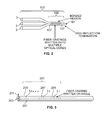
- FIG. 1B is a side view of the shape sensing system of FIG. 1 , including a bonded region.
- FIG. 2 is a perspective view of a variation of a shape sensing or measuring system including an antireflection end.
- FIG. 4 is a perspective view of a variation of a twist measurement system for shape sensing or measuring utilizing a CCD array spectrometer.
- FIG. 4A is a view of an angled fiber grating written into optical fiber.
- FIG. 4B shows an optical fiber with a reflecting end.
- FIG. 4C shows a beamsplitter and fiber loop acting as an end reflector.
- FIG. 4D illustrates a reflecting end similar to FIG. 4C using a tight bend to minimize overall diameter.
- FIG. 5 is a perspective view of a variation of a shape sensing or measuring system utilizing two separate CCD spectrometers.
- FIG. 6 is an end view of a variation of a photonic crystal fiber.
- FIG. 7B is a magnified side view of a photonic crystal fiber and fiber grating of FIG. 7A shown in a bent configuration.
- FIG. 7C is a line graph showing the spectral profiles for light reflected from the fiber gratings of FIGS. 7A and 7B .
- FIG. 8A is a magnified side view of a photonic crystal fiber having a linear index of refraction gradient across the core.
- FIG. 8B is a graphical diagram of the index of refraction for the fiber of FIG. 8A .
- FIG. 8C is a magnified side view of a variation of a photonic crystal fiber and a fiber grating written into it.
- FIG. 9A is a magnified side view of a photonic crystal fiber with a linear index of refraction gradient across the core and a fiber grating written into it.
- FIG. 9B is a magnified side view of a photonic crystal fiber and fiber grating as in FIG. 9A shown in a bent configuration.
- FIG. 9C is a magnified side view of a photonic crystal fiber and fiber grating as in FIG. 9A shown in a bent configuration.
- FIG. 9D is a line graph showing the spectral profiles for light reflected from the fibers of FIGS. 9A-9C .
- FIG. 10 is a cross sectional magnified perspective view of a variation of a shape sensing system including birefringent axes.
- FIG. 11 is a diagram of a twist measurement system that measures changes in the polarization state of light reflected from a birefringent fiber grating written into low birefringence optical fiber.
- FIG. 12A is a spectral profile reflected from a birefringent fiber grating written into low birefringence optical fiber illuminated by un-polarized light
- FIG. 12B is a spectral profile reflected from a birefringent fiber grating written into low birefringence optical fiber with a polarizer aligned to the polarization of one spectral peak.
- FIG. 12C is a spectral profile reflected from a birefringent fiber grating written into low birefringence optical fiber illuminated with a polarizer aligned to the second spectral peak that may be nearly orthogonal to that of FIG. 12B .
- FIG. 13 illustrates a conventional manually-steerable catheter.
- FIG. 14 illustrates a variation of a robotically-driven steerable catheter.
- FIGS. 15A-15C illustrate a variation of a robotically-steerable catheter having an optical fiber positioned along the wall of the catheter.
- FIGS. 16A-16D illustrate implementations of an optical fiber with a grating to an elongate instrument such as a robotically-steerable catheter.
- FIGS. 17A-17D illustrate implementation of an optical fiber with a grating to an elongate instrument such as a robotically-steerable catheter.
- FIG. 18 illustrates a cross sectional view of an elongate instrument such as a catheter including an optical fiber with optical gratings.
- FIG. 19 illustrates a cross sectional view of an elongate instrument such as a catheter including a multi-fiber optical grating configuration.
- FIG. 20 illustrates a cross sectional view of an elongate instrument such as a catheter including a multi-fiber grating configuration.
- FIGS. 21A-21B illustrate top and cross sectional views of an elongate instrument such as a catheter having a multi-fiber structure with optical gratings.
- FIGS. 22A-22B illustrate top and cross sectional views of an elongate instrument such as a catheter having a multi-fiber structure with optical gratings.
- FIGS. 23A-23B illustrate top and cross sectional views of an elongate instrument such as a catheter having a multi-fiber structure with optical gratings.
- FIGS. 24A-24H illustrate cross sectional views of elongate instruments with various fiber positions and configurations.
- FIG. 25A-25B show a perspective view of a surgical system with a shape sensing system mounted thereon.
- FIG. 26A-26C show a variation of a robotic surgical system.
- FIG. 1B illustrates one variation of a shape sensing or measuring system 57 having three aligned fibers, e.g., optical fibers 3 .
- the system includes a combined, adhered, fused or bonded region 51 .
- the system may also include end regions 53 and 55 where the optical fibers 3 are mechanically independent and may be easily interfaced to connectors or spliced.
- the bonded region 51 may be designed such that when light is coupled into any one of the optical fibers 3 there is virtually no or substantially no cross coupling in the bonded region 51 to any other of the optical fibers 3 .
- the region 51 may allow for good strain transfer between the optical fibers 3 with minimal or virtually no cross coupling.
- one or more fiber gratings can be written onto the optical fibers.
- fiber gratings include, but are not limited to: Bragg fiber gratings, and long period fiber gratings.
- Bragg fiber gratings may be utilized, including, for example, those with (1) uniform period, (2) apodized fiber gratings designed for spectral shape and/or (3) chirped fiber gratings that have a non-uniform period and are designed to reflect a broad wavelength spectrum.
- FIG. 1A illustrates one variation of a process or mechanism 1 for bonding multiple fibers together such that good strain transfer may be obtained between the fibers.
- the process or mechanism 1 may be utilized to produce the shape sensing system 57 illustrated in FIG. 1B .
- Clamps 5 and 7 are used to hold the three optical fibers 3 in place and to place them under tension via mechanical stages 9 and 11 (e.g., motorized translation stages), which can exert a controllable force on the clamped optical fibers 3 in the directions indicated by arrows A & B.
- a heater 13 or other temperature altering device or substance may be used to increase the temperature substantially uniformly on a region 15 of the clamped optical fibers 3 .
- the heater 13 may be, e.g., a butane flame arrangement or a metallic tube that is resistively heated, or any other device suitable for controllably heating or raising the temperature of the optical fibers.
- the optical fibers 3 By controlling a drawing force exerted by mechanical stages 9 and 11 and increasing the temperature of region 15 of the optical fibers 3 , the optical fibers 3 will soften and may be drawn down together. This in turn establishes a region where the optical fibers 3 are physically bonded.
- the bonded region may be tapered.
- Various types of optical fibers 3 may be utilized, including, for example, quartz optical fibers, sapphire optical fiber and optical fiber composed of other crystalline materials.
- the bonded region will include an area where the quartz surface of the optical fibers has melted, and upon cooling, solidified to form a quartz bond region.
- procedures for processing the optical fibers 3 illustrated in FIGS. 1A and 1B may be similar to those employed with biconical fused 2 by 2 and 3 by 3 couplers, which are established by commercial vendors such as Amphenol and Gould Fiber Optics.
- the surfaces of the optical fibers 3 are bonded for strain transfer between the optical fibers 3 .
- the tapers associated with the bonded region 51 of optical fibers 3 may be less severe than those created using conventional fiber coupler technology and the shape sensing or measuring system 57 may be mechanically more robust.
- the bonded region of the fibers may be fused in a manner similar to that used to form fused biconical couplers in the telecommunication industry.
- the shape sensing or measuring system 57 of FIG. 1B may be cleaved approximately in the center of bonded region 51 , creating cleaved shape sensing or measuring system 103 .
- the end 101 of the cleaved system 103 may be processed to minimize back reflection. For example, this may be accomplished by forming a spherical end at end 101 or by adding an antireflection coating to end 101 or by forming an angled cleave.
- one or more fiber gratings 107 may be written onto the optical fibers 3 of system 103 in bonded region 105 , thereby enabling the measurement of bend in two orthogonal directions or twist or roll along the length of bonded region 105 .
- the fiber gratings may be written onto the cores of the optical fibers.
- the cleaved system 103 may be useful for a variety of applications. For example, for applications involving robotically or manually controlled medical catheters, where it is desirable to minimize the overall size of the catheter, particularly at the distal end.
- the cleaved system 103 can reduce the overall cost of a shape sensing system, which is important for applications involving disposable components, e.g., disposable catheters.
- the cleaved system 103 may also be useful to create a shape sensing system that allows for a single ended read out system.
- the systems associated with FIGS. 1 and 2 may include polarization preserving or maintaining optical fiber when it is desirable to be able to define and control the polarization state of light propagating through the system.
- optical frequency domain reflectometer systems that require polarization control to operate effectively may include polarization preserving optical fiber.
- a number of different types of polarization preserving optical fiber may be utilized.
- One example is elliptical core optical fiber, that may be made with one or more flat sides. This may be done by machining flats onto the side of the perform and then drawing an optical fiber with the same geometry. The flat provides a reference to orientation.
- An example of this type of fiber is D shaped optical fiber, originally developed and sold commercially by Andrew Corporation.
- the flat side feature of these fibers allows the polarization preserving fibers to be fabricated with sides angled such that the fibers may be placed and drawn with specific desirable orientations to optimize shape sensing capabilities.
- FIG. 3 illustrates an example of a shape sensing system which allows for the measurement of twist or roll by measuring changes in the polarization state of reflected light from regions along the axis of a probe.
- a shape sensing system which allows for the measurement of twist or roll by measuring changes in the polarization state of reflected light from regions along the axis of a probe.
- the system includes an optical fiber 201 with a light guiding core 203 having a series of tilted fiber gratings 205 , 207 and 209 written along the core 203 .
- One or more optical fibers may be utilized in the system.
- the optical fibers may be bonded together as described above according to the systems of FIGS. 1-2 .
- the fiber gratings 205 , 207 and 209 may be tilted so that they are polarization sensitive or have a polarization dependence corresponding to the direction of tilt.
- the direction of tilt can vary. In this particular variation, the direction of tilt is along the axis 211 .
- Each of the fiber gratings 205 , 207 and 209 may be written at a different wavelength so that multiple fiber gratings may be interrogated using standard wavelength division multiplexing techniques.
- each of the successive tilted fiber gratings 205 , 207 , 209 may be written at the same wavelength with low reflectivity or optionally two or more of the fiber gratings may be written at the same wavelength.
- Fiber gratings may be interrogated using well known standard optical frequency domain reflectometry techniques developed by NASA.
- the tilted fiber gratings 205 , 207 and 209 according to any of the above described variations indicate an array 301 of n fiber gratings representing n points along the optical fiber 201 where twist may be measured.
- the coupler 309 also splits the light beam 307 into the light beam 311 which is directed into the optical fiber 201 and the light beam 311 can reach a reference tilted fiber grating 317 that is positioned in a location where the twist of the optical fiber 201 is known.
- a portion 319 of the light beam 311 is reflected by the tilted reference fiber grating 317 along the optical fiber 201 to the coupler 309 .
- the portion of light beam 319 is directed as the light beam 321 to the polarizing beamsplitter 323 , which splits the light beam 321 into the orthogonal s and p polarization components (light beams 325 and 327 respectively) via the fiber lines 331 and 329 respectively.
- the light beams 325 and 327 reach the 2 by 1 optical switch 333 , which may alternately direct the light beams 325 and 327 onto a CCD array spectrometer 337 (or reflectometer or detector or other instrument for measuring light or the properties of light or other spectral read out system).
- the CCD array spectrometer 337 detects the relative amount of light in the s and p polarization state such that the twist orientation of the reference fiber grating 317 may be determined.
- the light beams 343 and 345 are directed into the 2 by 1 switch 333 which in turn alternates these two light beams onto the CCD array spectrometer 337 so that the degree of polarization for each wavelength associated with the fiber gratings of the fiber grating array 301 may be assessed allowing the degree of twist along the region of the fiber 201 associated with the fiber grating array 301 to be measured.
- the light beam component 353 may have a preferred polarization state because of the steep angle (relative to the longitudinal axis of the optical fiber) associated with the tilted fiber gratings 301 .
- the degree to which the light is polarized depends upon the angle of the tilt of the fiber grating.
- the light beam 311 may have a second component 355 and the second component 355 may be guided by the core 357 of the optical fiber 201 .
- the component 357 may be partially polarized through the action of the tilted fiber gratings 301 and may propagate to the end 347 of the optical fiber 201 .
- provisions may be included in the system so that the light beam 355 may reflect back.
- FIG. 4 b shows the fiber end 347 of optical fiber 201 having a reflector 361 connected thereto.
- the reflector 361 can be a metallic coating that may be aluminum, silver, or gold or made from other reflective materials.
- the reflector 361 may be a single or multiple layer dielectric coating.
- the reflector 361 coat may be obtained by using polishing or cleaving techniques to create a flat end 347 and/or having the end terminate in a region having a different or significantly different index of refraction from that of the optical fiber, such as, for example, air or a high index liquid or fluid.
- another method for directing a portion of the light beam 355 back into the system involves connecting the fiber end 347 via a splice 365 to a first end 367 of a coupler 369 .
- Second and third ends of the coupler 369 may form a loop 371 that directs back to the coupler 369 , and may direct a portion of the light beam 355 back into the optical fiber 201 .
- a portion 373 of the loop 371 may be bent very sharply using techniques that are available commercially from companies such as Amphenol. The tight bend 373 allows for a compact package.
- Such a configuration may be required or suitable for use in applications such as manually or robotically controlled catheters where it may be desirable for the overall diameters of the system to be minimized.
- FIG. 5 shows an alternate variation of the shape sensing or measuring system of FIG. 4 which can measure twist.
- Two separate CCD spectrometers are provided.
- Spectrometer 401 may be used to monitor the light beam signals from the optical fiber 331 and the spectrometer 403 may be used to monitor the light beam signals from the optical fiber 329 .
- These two separate CCD spectrometers may be used in place of the 2 by 1 switch 333 and the single CCD spectrometer 337 (illustrated in FIG. 4 ), while performing a similar function.
- An advantage of the variation illustrated in FIG. 5 which utilizes two separate spectrometers is that the s and p polarization states of the tilted fiber gratings may be monitored continuously with no or minimal loss of signal due to the switching operation.
- An advantage of the variation illustrated in FIG. 4 is that a single CCD spectrometer is used for monitoring the light signals, thereby minimizing or eliminating the possibility of relative drift that may occur in the response of multiple CCD spectrometers. Such a drift could result in an error in measuring the degree of polarization and the twist.
- the use of a single CCD spectrometer may also be more cost effective, as CCD spectrometers in general may be more expensive than a 2 by 1 switch.
- a spectrometer or reflectometer or detector or other spectral read out system may be used in the variations described herein.
- Crystal Fibres A/S of Birkerod, Denmark offers commercial photonic crystal fibers of this type having core diameters of up to 35 microns (LMA-35) that allow single mode operation at telecom wavelengths associated with conventional single mode optical fiber.
- the separation between the outer opposite edges of the fiber core 453 diameter may be large enough such that when the fiber 451 is bent, there is a significant strain difference between the opposite edges or positions across the fiber core 453 .
- the strain differences may allow various shape measurements of the fiber 451 to be made.
- Large core optical fibers may vary in size. For example a large core optical fiber may have a diameter greater than or equal to about 10 microns or greater than or equal to about 20 microns. Optionally, the large core optical fiber may be greater than 20 microns or may be 30 or 40 microns.
- FIG. 7A shows a side view of one variation of a single photonic crystal fiber (PCF) 501 in a substantially straight configuration.
- a fiber grating 503 is written across the core 505 of the PCF 501 .
- the reflected light beam from the fiber grating 503 may have a spectral profile wavelength/intensity curve similar to 507 (shown in the graph of FIG. 7C ).
- FIG. 7B shows the PCF 501 bent into a curved position such that the period 509 of the fiber grating 503 on the tension side of the fiber core 505 is longer than the period 511 of the fiber grating 503 on the compression side of the fiber core 505 .
- the effective period of the fiber grating 503 will vary across the core and when the fiber grating is illuminated in this state by a broadband light beam the spectral profile 509 reflected from the fiber grating will be broadened. By measuring this broadening or the width or change of the spectral profile, the bending of the fiber may be measured.
- FIG. 8A shows a side view of one variation of a PCF 551 having a large core 553 that has a linear index of refraction gradient across the core.
- the index of refraction varies from a lower value at the diametric top to a higher value at the diametric bottom, where the index of refraction may increase in the direction of arrow n.
- FIG. 8B shows the index of refraction increasing across the core 553 of the fiber 551 , where the index of refraction is low at the top of the core and higher at the bottom of the core.
- a fiber grating 557 may be written onto the PCF 551 and may have an effective period 559 near the diametric top of the core 553 (e.g., where an index of refraction is low) that is substantially shorter than the effective period 561 near the diametric bottom of the core 553 (e.g., where the index of refraction is higher).
- the fiber grating 557 of FIG. 8C will have a broadened spectral profile, similar to fiber grating 503 of optical fiber 501 when the optical fiber 501 is bent.
- These configurations or methods effectively allow the spectral profile to be “biased” so that the direction of bend of the fiber may be determined. That is one side of the optical fiber core has a grating written into it that has a shorter period near one side than the other. When the fiber is bent it will elongate or shorten the period of the grating depending on the direction of bend. This in turn will change the overall spectral profile from its initial biased state where the period varies across the core.
- the linear index of refraction across the core could be designed so that when the fiber 551 is straight it will have a spectral profile corresponding to a bend diameter of 10 mm.
- the shift of the spectral profile effectively provides a “bias”. That is when the fiber is bent in a direction along the axis of the refractive index gradient across the core 557 the spectral shift is distinct from an equal bend in the opposite direction. This effect is also illustrated in FIG. 9 below.
- the period 559 at the top of the core 557 and the period 561 at the bottom of the core 557 may have a configuration as shown in FIG. 8B .
- PCF 551 is illuminated by a broad band light beam, this results in a reflected wavelength/intensity spectral profile 601 (shown in FIG. 9D ).
- the period 603 associated with the top of the fiber grating is moved to a longer period, compared to 559 , and the bottom period 605 is moved toward a shorter period, compared to that of 561 , due to compression.
- the period 609 becomes shorter than the period 559 and the period 611 becomes longer than the period 561 .
- the spectral profile 613 (shown in FIG. 9D ) associated with the fiber grating 557 in this condition is broadened at its full width half maximum in comparison to the spectral profile 601 .
- the first mechanism involves the use of ultraviolet light in a manner similar to that used in the fabrication of fiber gratings. For example, exposure of a germanium doped core to ultraviolet light at the appropriate wavelength may result in an increase in the index of refraction of the core.
- the appropriate wavelength may be about 240 nm which is commonly used or a series of other wavelengths that are described in the literature. Also, by adjusting the ultraviolet or other light exposure intensity and time across the core, the index of refraction profile may be adjusted.
- Another mechanism for inducing or creating a refractive index includes adjusting the position and/or concentration of dopant material, such as germanium, during the fabrication process associated with making an optical fiber.
- dopant material such as germanium
- the geometry and position of holes in the optical fiber may be adjusted.
- a shape sensing or measuring system may have two dimensional bend sensor capabilities.
- the capabilities may be provided by adding additional features to a PCF. For example, holes may be added to a PCF fiber to make it birefringent and/or polarization preserving.
- a large core optical could include a tilted or birefringent fiber grating to support or allow for the measurement of twist.
- another variation of a shape sensing or measuring system includes an optical fiber having birefringent axes 653 and 655 .
- an index of refraction variation or gradient may be established that may be linear, similar to that shown in FIG. 8 .
- two effective fiber gratings may be established along each of the birefringent axes 653 and 655 .
- the two effective fiber gratings can be used to measure yaw and pitch along the two orthogonal axes by the methods described in association with FIGS. 7-9 .
- the fiber gratings may be used to measure twist or roll along the fiber or axes.
- the fiber gratings may be interrogated independently by separating out the two polarization states onto a fiber grating read out unit.
- Such read out units may be similar to or include, for example, those used by E. Udd to support fiber grating damage assessment systems as described in: M, Kunzler, E. Udd, S. Kreger, M. Johnson and V. Henrie, “Damage Evaluation and Analysis of Composite Pressure Vessels Using Fiber Bragg Gratings to Determine Structural Health”, Proceedings of SPIE, Vol. 5758, p. 168, 2005; and E.
- a fiber grating or second fiber grating 659 may be written at an angle at a wavelength that is different from that associated with fiber grating 657 in order to establish or measure twist of the fiber.
- the orientation of the tilted fiber grating 659 could be controlled relative to the birefringent axes.
- the tilted fiber grating 659 may be written along an axis that is between the birefringent axes.
- FIG. 11 shows a variation of a system 801 that may be used to measure twist or twist angle or roll at a position along a fiber.
- a light source 803 that may be spectrally broad and depolarized is used to generate a light beam 805 that is coupled into the fiber end 807 and directed toward a three port circulator 809 .
- the light beam 805 is redirected by the circulator 809 to the optical fiber 811 and the light beam propagates to a birefringent fiber grating 813 written onto the optical fiber 811 .
- the birefringent fiber grating 813 may be made by using short femto-second light pulses that induce birefringence locally through the interaction of the light pulses with the optical fiber 811 . This technique has been pioneered by the Communication Research Center in Canada.
- the birefringence of the optical fiber 811 causes a spectral splitting of the fiber grating 813 so that the fiber grating's reflection spectra results in two distinct spectral peaks 851 and 853 illustrated by FIG. 12 a .
- the peaks 851 and 853 appear to have approximately equal intensity amplitude when illuminated by a depolarized light source. However the spectral peaks 851 and 853 are polarization dependent.
- the spectral peak 851 can be nearly extinguished as shown in FIG. 12 b .
- the spectral peak 853 can be nearly extinguished by rotating the polarizer to a position that is nearly orthogonal to the position where the peak 851 is extinguished as shown in FIG. 12 c.
- the reflected light beam 815 from the birefringent fiber grating 813 is directed back to the circulator 809 and directed via the fiber segment 817 to the end 819 of the polarizer 821 , which may be a fiber polarizer.
- the light beam 815 is then directed into the spectrometer 823 or other spectral read out system or detector that is used to measure the wavelength and amplitude of the light beam 815 .
- the birefringent fiber grating 813 is twisted relative to the position of the end 819 of the fiber polarizer 821 , the relative amplitudes of the peaks 851 and 853 change and their ratio can be used to measure twist.
- a two by two coupler may replace the circulator 809 and serve a similar function.
- Ordinary conventional single mode optical fiber with characteristics similar to Corning SMF-28 used for standard telecommunication applications may be used for all fiber in the system.
- the fiber used for the fiber polarizer used in the polarizer position associated with polarizer 821 may differ however.
- the position of the splice 819 of the polarizer end to the fiber 817 may be fixed to a table top and the birefringent fiber grating may be rotated through an angle of approximately 180 degrees. The resolution of the system may be about 2 degrees over this span.
- the optical fibers may be bonded together as described above according to the systems of FIGS. 1-2 , or a single optical fiber or large core optical fiber may be utilized or one or more optical fibers or large core optical fibers may be utilized, which are bonded or not bonded.
- a fiber grating may be written into at least one of the optical fibers in such a way that the writing process results in birefringence of the fiber grating. This may be performed according to methods described in the literature and known by persons of skill in the art.
- one or more fibers may be utilized and variety of fiber types may be utilized, e.g., optical fibers, or any fibers known in the art that can support fiber gratings.
- the positioning, orientation, deflection, displacement, bend, strain, yaw, pitch, roll, twist and/or temperature of the fibers may be measured.
- the various systems may also control the operation of other functions of the devices, such as imaging devices, ablation devices, cutting tools, or other end effectors.
- the various systems, devices or instruments may be controlled using a closed-loop servo control in which an instrument is moved in response to a command, and then the determined position may be utilized to further adjust the position.
- a closed-loop servo control in which an instrument is moved in response to a command, and then the determined position may be utilized to further adjust the position.
- an open loop control may be used in which an instrument is moved in response to a user command, the determined position is then displayed to the user, and the user can then input another command based on the displayed position.
- the shape sensing or measuring systems described herein may be utilized with a conventional manually-steerable catheter 700 .
- pullwires 702 may be selectively tensioned through manipulation of a handle 703 on the proximal portion of the catheter structure 700 to make a more flexible distal portion 705 of the catheter bend or steer controllably.
- the handle ( 703 ) may be coupled, rotatably or slidably, for example, to a proximal catheter structure ( 734 ) which may be configured to be held in the hand, and may be coupled to the elongate portion ( 735 ) of the catheter ( 700 ).
- the shape sensing or measuring systems described herein may be utilized with a robotically-driven steerable catheter 706 , e.g., similar to those described in detail in U.S. patent application Ser. No. 11/176,598, incorporated by reference herein in its entirety for all purposes.
- This catheter 706 has some similarities with the manually-steerable catheter 700 of FIG. 13 in that it has pullwires or similar control elements 710 associated distally with a more flexible section 708 configured to steer or bend when the pullwires or control elements 710 are tensioned in various configurations, as compared with a less steerable proximal portion 707 configured to be stiffer and more resistant to bending or steering.
- the control elements can be flexible tendons or pullwires, or other mechanical structures that allow for steering or defletion of the catheter ( 706 ).
- the depicted variation of the robotically-driven steerable catheter 706 comprises proximal axles or spindles 709 configured to primarily interface not with fingers or the hand, but with an electromechanical instrument driver configured to coordinate and drive, with the help of a computer, each of the spindles 709 to produce precise steering or bending movement of the catheter 706 .
- the spindles ( 709 ) may be rotatably coupled, e.g., via pullwires, to a proximal catheter structure ( 732 ) which may be configured to mount to an electromechanical instrument driver apparatus, such as that described in the aforementioned U.S. patent application Ser.
- the shape sensing or measuring systems described herein may be incorporated or integrated in such catheter, sheaths or instruments to provide information regarding spatial position, shape, twist, roll, orientation, etc., of the catheters, sheaths or instruments.
- the examples and illustrations that follow are made in reference to a robotically-steerable catheter such as that depicted in FIG. 14 , but as would be apparent to one skilled in the art, the same principles may be applied to other elongate instruments, such as the manually-steerable catheter depicted in FIG. 13 , or other elongate instruments, highly flexible or not, from suppliers such as the Ethicon Endosurgery division of Johnson & Johnson, Inc., or Intuitive Surgical, Inc.
- a variation of a robotically-steerable catheter 706 is depicted having an optical fiber 712 .
- the fiber may be a fiber shape sensing or measuring system according to any of the embodiments described herein.
- the fiber 712 may be positioned along one aspect of the wall of the catheter 706 .
- the fiber is not positioned coaxially with the neutral axis of bending 711 in the bending scenarios depicted in FIGS. 15B and 15C . Indeed, with the fiber 712 attached to, or longitudinally constrained by, at least two different points along the length of the catheter 706 body and unloaded from a tensile perspective relative to the catheter body 733 in a neutral position of the catheter body 733 such as that depicted in FIG.
- the longitudinally constrained portion of the fiber 712 would be placed in tension when the catheter 706 is deflected as depicted in FIG. 15B , while the longitudinally constrained portion of the fiber 712 would be placed in compression when the catheter 106 is deflected as depicted in FIG. 15C .
- the optical fiber grating can comprise a Bragg or other grating. Examples of fiber optic Bragg fiber sensing technology may be available from Luna Innovations, Inc. of Roanoke, Va., Micron Optics, Inc., of Atlanta, Ga., LxSix Photonics, Inc., of Quebec, Canada, and Ibsen Photonics A/S, of Denmark.
- a broadband reference reflector may be positioned near the proximal end of the fiber in an operable relationship with the optical grating wherein an optical path length is established for each reflector/grating relationship comprising the subject fiber grating sensor configuration; additionally, such configuration may also comprise a reflectometer, such as a frequency domain reflectometer, to conduct spectral analysis of detected reflected portions of light waves.
- the most distal constraint ( 730 ) may be configured to disallow longitudinal or axial movement of the fiber ( 712 ) relative to the catheter body ( 733 ) at the location of such constraint ( 730 ), while the more proximal constraint ( 730 ) may merely act as a guide to lift the fiber ( 712 ) away from the walls of the lumen ( 731 ) at the location of such proximal constraint ( 730 ).
- both the more proximal and more distal constraints ( 730 ) may be configured to disallow longitudinal or axial movement of the fiber ( 712 ) at the locations of such constraints, and so on. As shown in the embodiment depicted in FIG.
- the lumen ( 731 ) in the region of the proximal catheter structure ( 732 ) is without constraints to allow for free longitudinal or axial motion of the fiber relative to the proximal catheter structure ( 732 ).
- Constraints configured to prohibit relative motion between the constraint and fiber at a given location may comprise small adhesive or polymeric welds, interference fits formed with small geometric members comprising materials such as polymers or metals, locations wherein braiding structures are configured with extra tightness to prohibit motion of the fiber, or the like.
- Constraints configured to guide the fiber ( 712 ) but to also allow relative longitudinal or axial motion of the fiber ( 712 ) relative to such constraint may comprise small blocks, spheres, hemispheres, etc defining small holes, generally through the geometric middle of such structures, for passage of the subject fiber ( 712 ).
- FIG. 16B The embodiment of FIG. 16B is similar to that of FIG. 16A , with the exception that there are two additional constraints ( 730 ) provided to guide and/or prohibit longitudinal or axial movement of the fiber ( 712 ) relative to such constraints at these locations.
- each of the constraints is a total relative motion constraint, to isolate the longitudinal strain within each of three “cells” provided by isolating the length of the fiber ( 712 ) along the catheter body ( 733 ) into three segments utilizing the constraints ( 730 ).
- each of the constraints is a total relative motion constraint, to isolate the longitudinal strain within each of three “cells” provided by isolating the length of the fiber ( 712 ) along the catheter body ( 733 ) into three segments utilizing the constraints ( 730 ).
- the proximal and distal constraints ( 730 ) may be total relative motion constraints, while the two intermediary constraints ( 730 ) may be guide constraints configured to allow longitudinal or axial relative motion between the fiber ( 712 ) and such constraints at these intermediary locations, but to keep the fiber aligned near the center of the lumen ( 731 ) at these locations.
- FIG. 16C an embodiment similar to those of FIGS. 16A and 16B is depicted, with the exception that entire length of the fiber that runs through the catheter body ( 733 ) is constrained by virtue of being substantially encapsulated by the materials which comprise the catheter body ( 733 ).
- the embodiment of FIG. 16C does have a lumen ( 731 ) to allow free motion of the fiber ( 712 ) longitudinally or axially relative to the proximal catheter structure ( 732 ), there is no such lumen defined to allow such motion along the catheter body ( 733 ), with the exception of the space naturally occupied by the fiber as it extends longitudinally through the catheter body ( 733 ) materials which encapsulate it.
- FIG. 16D depicts a configuration similar to that of FIG. 16C with the exception that the lumen ( 731 ) extends not only through the proximal catheter structure ( 732 ), but also through the proximal portion ( 707 ) of the catheter body ( 733 ); the distal portion of the fiber ( 712 ) which runs through the distal portion of the catheter body ( 733 ) is substantially encapsulated and constrained by the materials which comprise the catheter body ( 733 ).
- FIGS. 17A-17D depict embodiments analogous to those depicted in FIGS. 16A-D , with the exception that the fiber ( 12 ) is positioned substantially along the neutral axis of bending ( 711 ) of the catheter body ( 733 ), and in the embodiment of FIG. 17B , there are seven constraints ( 730 ) as opposed to the three of the embodiment in FIG. 16B .
- FIG. 18 a cross section of a portion of the catheter body ( 733 ) of the configuration depicted in FIG. 16C is depicted, to clearly illustrate that the fiber ( 712 ) is not placed concentrically with the neutral axis ( 711 ) of bending for the sample cross section.
- FIG. 19 depicts a similar embodiment, wherein a multi-fiber bundle ( 713 ), such as those available from Luna Technologies, Inc., is positioned within the wall of the catheter rather than a single fiber as depicted in FIG. 18 , the fiber bundle ( 713 ) comprising multiple, in this embodiment three, individual (e.g., smaller) fibers or fiber cores ( 714 ).
- a structure such as that depicted in FIG.
- FIG. 19 is placed in bending in a configuration such as that depicted in FIG. 15B or 15 C, the most radially outward (from the neutral axis of bending ( 711 )) of the individual fibers ( 714 ) experiences more compression or tension than the more radially inward fibers.
- FIG. 20 which shows a cross section of the catheter body ( 733 ) portion a configuration such as that depicted in FIG.
- the lowermost two fibers comprising the bundle ( 713 ) may be configured to experience compression, while the uppermost fiber experiences tension.
- the opposite would happen with an upward bending scenario such as that depicted in FIGS. 23A and 23B (cross section).
- FIGS. 24A-24H various configurations may be employed, depending upon the particular application, such as those depicted in FIGS. 24A-24H .
- each of the cross sectional embodiments of FIGS. 24A-24H is depicted without reference to lumens adjacent the fibers, or constraints (i.e., each of the embodiments of FIGS. 24A-24H are depicted in reference to catheter body configurations analogous to those depicted, for example, in FIGS. 16C and 17C , wherein the fibers are substantially encapsulated by the materials comprising the catheter body ( 733 ); additional variations comprising combinations and permutations of constraints and constraining structures, such as those depicted in FIGS. 4A-5D , are within the scope of this invention.
- FIG. 24A depicts an embodiment having one fiber ( 712 ).
- FIG. 24B depicts a variation having two fibers ( 712 ) in a configuration capable of detecting tensions sufficient to calculate three-dimensional spatial deflection of the catheter portion.
- FIG. 24C depicts a two-fiber variation with what may be considered redundancy for detecting bending about a bending axis such as that depicted in FIG. 24C .
- FIGS. 24D and 24E depict three-fiber configurations configured for detecting three-dimensional spatial deflection of the subject catheter portion.
- FIG. 24F depicts a variation having four fibers configured to accurately detect three-dimensional spatial deflection of the subject catheter portion.
- FIGS. 24A-24H depict embodiments similar to 24 B and 24 E, respectively, with the exception that multiple bundles of fibers are integrated, as opposed to having a single fiber in each location.
- FIGS. 24A-24H depict a cross section of an elongate instrument comprising at least one optical fiber, may be utilized to facilitate the determination of bending deflection, torsion, compression or tension, and/or temperature of an elongate instrument.
- the 3-dimensional position, shape, twist or roll of an elongate member may be determined by determining the incremental curvature experienced along various longitudinal sections of such elongate member.
- the position of the distal portion and more proximal portions in three-dimensional space by virtue of the knowing that the sections are connected, and where they are longitudinally relative to each other.
- variations of embodiments such as those depicted in FIGS. 24A-24H may be utilized to determine the position of a catheter or other elongate instrument in 3-dimensional space.
- fiber optic grating analysis may be utilized.
- the various shape sensing or measuring systems and/or fibers described herein may be integrated or incorporated in various elongate members or instruments such as manual or robotic catheters or catheter guide instruments or sheath instruments to sense or measure the shape, twist, roll, position, orientation, etc. of such members and/or instruments.
- FIG. 25A illustrates a perspective view of a da Vinci telesurgical system 720 including its operator control station 722 and surgical workstation 724 .
- the surgical workstation 724 comprises a cart 726 , which supports the robotic arms 728 .
- One or more fibers 716 (e.g., a shape sensing or measuring systems including optical fibers and/or Bragg fiber sensors or gratings) according to the variations described herein may be disposed along at least a portion of the length of each arm 728 .
- multiple fibers 716 may be disposed on each arm 728 .
- separate fiber 716 may be disposed on each link of the robotic arm 728 .
- fiber 716 may be operably coupled to interventional and/or diagnostic instruments, such as the depicted robotic arm 728 , utilizing bands, clips, fasteners, a layer of at least partially encapsulating material, or the like, distributed along the length of the robotic arm or other structure to maintain the position of the fiber 716 relative to the position of the pertinent portions of such structure.
- telesurgical system 720 includes a cart 726 carrying three robotically controlled manipulator arms 728 , each having a fiber 716 disposed thereon, and extending along the catheters 732 operatively coupled to the arms 728 .
- the fibers 716 may be routed through the support structure of the arms 728 to the catheters 732 .
- the fibers 716 may be freely connected from a position determining system 730 directly to each of the catheter assemblies 732 .
- the fibers or shape sensing or measuring systems have been described as being disposed on, coupled to or located on a robotic arm, instrument, catheter, and/or tool.
- the fibers or fiber bundles may be mounted to or installed on the exterior surface or housing of the robotic instrument.
- one or more fibers may be routed on the external housing of a robotic arm of the Intuitive Surgical da Vinci system, a Mako system, or a Accuray system.
- one or more fibers may be fastened on the outer surface of the instrument of a Intuitive Surgical, Stereotaxis, or NeoGuide system or apparatus.
- a fiber may be attached to a tool instrument or end-effector which may be operably coupled with the distal end of an instrument.
- the fibers may be installed within or integrated into the robotic instrument itself.
- one or more fiber sensors may be routed internally to the robotic arm of a Intuitive Surgical da Vinci system, a Mako system, or a Accuray system.
- one or more fibers may be located within the catheter instrument of a Intuitive Surgical catheter, Stereotaxis catheter, or NeoGuide catheter.
- a fiber may be built into a tool instrument or end-effector at the distal end of a catheter instrument. Accordingly, as used herein, the term “disposed on” shall include without limitation all of these described methods of providing the described structure with a fiber or shape sensing or measuring system, and shall not be limited to any particular mounting method or location relative to the structure.
- a robotic catheter system 932 may include an operator control station 902 located remotely from an operating table 922 , to which a instrument driver 916 and instrument 918 are coupled by a instrument driver mounting brace 920 .
- a communication link 914 transfers signals between the operator control station 902 and instrument driver 916 via an electronics rack housing PCBs or other electronic equipment.
- the instrument driver mounting brace 920 of the depicted embodiment is a relatively simple, arcuate-shaped structural member configured to position the instrument driver 916 above a patient (not shown) lying on the table 922 .
- Examples of systems in which the shape sensing or measuring systems described herein may be incorporated to measure and sense shape, position, etc. of such systems include, the SenseiTM Robotic Catheter System from Hansen Medical, Inc. in Mountain View, Calif., U.S.A. and the ArtisanTM Control Catheter also from Hansen Medical, Inc. in Mountain View, Calif., U.S.A.
- the shape sensing or measuring systems described herein may be utilized or incorporated into a robotic medical system for controlling a shapeable instrument or elongate member within an anatomical region.
- Shapeable medical instruments in most variations described herein, include any steerable devices, flexible catheters or more rigid arms or shafts whether such devices are used to access a region for advancement of a treatment device, or any actual shapeable treatment device.
- a shapeable device as used herein includes flexible, steerable, or otherwise positionable devices that are advanced to various tissue structures within the body. Such devices can assume a shaped configuration via manipulation or steering.
- shapeable devices include those flexible devices that conform to anatomic or other obstructions.
- shapeable instruments include a working end and one or more positioning elements that move the shapeable instrument.
- the positioning elements comprise control elements such as tendons wires, or other mechanical structures that are moved by one or more actuators to affect a shape or reposition the shapeable instrument.
- control elements such as tendons wires, or other mechanical structures that are moved by one or more actuators to affect a shape or reposition the shapeable instrument.
- catheter is one example of a shapeable instrument.
- the robotic medical system comprises a medical system for controlling a shapeable instrument within an anatomical region, where the shapeable instrument includes at least a working section and one or more positioning elements that move the shapeable instrument.
- One variation of the system includes a controller including a master input device, where the controller generates a position control signal in response to the master input device to position the working section at a desired position; one or more actuators operatively coupleable to the one or more positioning elements, where the actuators manipulate the positioning elements based on the position control signal to drive at least a first portion of the shapeable instrument to position the working section toward the desired position; a localization system configured to obtain a plurality of localized shape data from the first portion of the shapeable instrument; and where the controller generates a signal based upon a differential between the localized shape data and a desired configuration of the first portion of the shapeable instrument.
- the desired configuration of the first portion can include a desired position of the first portion or the desired position of the working section. Alternatively, or in combination, the desired configuration of the first portion comprises a desired shape of the first portion.
- the localization system can determine a position of the working section from the plurality of localized shape data.
- the desired configuration of the first portion comprises a desired position of the first portion and where controller generates the signal based upon the differential between the position of the working section and the desired position of the working section.
- the controller of the robotic medical system can be configured to derive a position of the working section from a kinematic model of the shapeable instrument.
- a variation of the robotic medical system includes a localization system that determines a shape of the first portion of the shapeable instrument from the plurality of localized shape data.
- the desired configuration of the first portion can comprises a desired shape of the first portion and where controller generates the signal based upon the differential between the shape of the first portion and the desired shape of the first portion.
- the localization system also determines a position of the working section from the plurality of localized shape data, and where the desired configuration of the first portion also includes a desired position of the first portion.
- the robotic medical system can also include a controller that is configured to feed the signal to the actuators such that the actuators manipulate one or more of the positioning elements using the signal to position the working section or the first portion of the shapeable instrument.
- the localization system comprises a fiber optic localization system configured to supply the plurality of localization data.
- the shapeable instrument can include at least one optic fiber and where the localization system is configured to measure a plurality of data of Rayleigh scatter of the optic fiber. The Rayleigh scatter data can be used to supplement or supply the localization data.
- a shapeable instrument comprises an elongate instrument body; an optical fiber coupled in a constrained manner to the elongate instrument body, the optical fiber is in communication with one or more optical gratings; and a detector operably coupled to a proximal end of the optical fiber and configured to detect respective light signals reflected by the one or more optical gratings.
- the system further includes a controller operatively coupled to the detector, wherein the controller is configured to determine a geometric configuration of at least a portion of the shapeable instrument based on a spectral analysis of the detected reflected portions of the light signals.
- Variations of the devices, systems and methods described herein can employ Bragg Fiber gratings as mentioned above. However, additional variations of the devices, systems and method contained in this disclosure can employ any number of optical gratings.
- the optical fiber may be substantially encapsulated in a wall of the elongate instrument body.
- the elongate instrument body may define an interior lumen, wherein the optical fiber is disposed in the lumen.
- the optical fiber may be disposed in an embedded lumen in a wall of the elongate instrument body.
- the elongate instrument body has a neutral axis of bending
- the optical fiber is coupled to the elongate instrument body so as to be substantially aligned with the neutral axis of bending when the elongate instrument body is in a substantially unbent configuration, and to move relative to the neutral axis of bending as the elongate instrument body undergoes bending.
- the optical fiber is coupled to the elongate instrument body so as to be substantially aligned with the neutral axis of bending regardless of bending of the elongate instrument body.
- the optical fiber is coupled to the elongate instrument body so as to remain substantially parallel to, but not aligned with, the neutral axis of bending regardless of bending of the elongate instrument body.
- One variation of a system may include three or more optical fibers.
- the fibers may have a bonded region to support strain transfer between the optical fibers and each of the optical fibers may have a fiber grating on each of the optical fibers along the bonded region.
- the bonded region of the fibers may be tapered and/or fusion bonded and/or configured such that a bend of an optical fiber may be determined by measuring a spectral profile of a reflection from the fiber grating bonded region.
- the fibers may be drawn and heated to establish a tapered bonded region wherein the surfaces of the fibers are bonded for strain transfer between the fibers.
- Each of the optical fibers may have a fiber grating written into the same position on each of the optical fibers along the bonded region.
- Various features and properties of the fibers may include the following. A plurality of fiber gratings of different wavelengths may be written into the bonded region. A chirped fiber grating may be written into the bonded fiber region.
- Low reflectivity fiber gratings of substantially the same wavelength may be written into the bonded region.
- the bonded region may have a cleaved end and the cleaved end may include an antireflection coating.
- the cleaved end may be melted to form a nonreflecting end.
- the cleaved end may be angled.
- a fiber grating may be angled or tilted to support, measure or allow for twist measurements.
- the fiber grating may be a birefringent fiber grating to support measure or allow for twist measurements.
- the optical fibers may be polarization preserving optical fibers.
- the polarization preserving optical fibers may be elliptical core optical fibers.
- the polarization preserving optical fibers may have at least one flattened side.
- the system may include an end region where the optical fibers are mechanically independent such that the fibers can be interfaced to connectors or spliced.
- the bonded region may be configured such that when light is coupled into any one of the optical fibers there is minimal or no cross coupling in the bonded region between any of the optical fibers.
- the optical fibers may extend along an axis of an elongate member or instrument of a surgical system for sensing the bend and/or twist of the elongate member and the elongate member may be manually or robotically controlled.
- a system may include a large core optical fiber.
- a fiber grating may be written onto said optical fiber.
- a light source may be provided for illuminating the fiber grating and a spectral read out system may measure a property of a reflection of light from the fiber grating
- the large core optical fiber may have a diameter of greater than 20 microns.
- the shape measuring system may also include a light source for illuminating the fiber grating.
- a bend of the optical fiber may be determined by measuring a spectral profile of the reflection from the fiber grating.
- the fiber grating may be an angled or tilted fiber grating to support twist measurements. An effective period or spacing of the fiber grating may vary across the core of the optical fiber.
- the optical fiber may have an index of refraction gradient across its core, which may be linear.
- the optical fiber may have a birefringent axes.
- the optical fiber may have index of refraction gradients along each birefringent axis.
- the optical fiber may have one or more tilted fiber gratings.
- the tilted fiber grating may be written along an axis that is not on one of the birefringent axes.
- the fiber grating may be a birefringent fiber grating that can support twist measurements.
- the optical fiber may extend along an axis of an elongate member instrument of a surgical system for sensing the bend and/or twist of the elongate member, which may be manually or robotically controlled.
- a variation of a system for measuring twist may include a light beam director, and an optical fiber having a first reference tilted fiber grating, a second tilted fiber grating and an end reflector.
- the system may include a polarizer and a spectrometer or spectral read out system.
- the light beam director may be configured to receive a light beam such that at least a portion of the light beam is directed from the light beam director into the optical fiber.
- the end reflector may be configured to reflect the light beam back through a tilted fiber grating to the light beam director, through a polarizer and onto a spectrometer or other spectral read out system to measure twist along the optical fiber at points associated with a tilted fiber grating.
- a polarization state of a wavelength associated with a fiber grating may be detected such that twist along a region of the fiber associated with the fiber grating can be measured.
- the light beam director may be a directional coupler having a first port, second port and an output port, and the system may also include a light source adapted to couple the light beam into the first port of the directional coupler. The portion of the light beam may be directed by the second port of the directional coupler into the optical fiber.
- the end reflector may reflect the light beam back through the tilted fiber gratings to the directional coupler where the light beam is directed by the output port of the directional coupler through a polarizer and onto a spectrometer or spectral read out system.
- the beam director may be a directional coupler.
- the optical fiber may have an array of second tilted fiber gratings.
- the end reflector may be a metallic coating.
- the end reflector may be a dielectric coating of one or more layers.
- the end reflector may be a directional coupler with a fiber loop connecting two coupler ports of the end reflector directional coupler.
- An output port of the light beam director may be configured to direct the light beam to a polarizing beamsplitter.
- the polarizing beamsplitter may have two outputs which are directed to a 2 ⁇ 1 switch, the 2 ⁇ 1 switch having an output directed to an output spectrometer.
- An output port of the light beam director may be configured to direct the light beam to a polarizing beamsplitter.
- the polarizing beamsplitter may have two outputs which are directed to a first output spectrometer and a second output spectrometer.
- the optical fiber may extend along an axis of an elongate member or instrument of a surgical system for sensing the twist of the elongate member.
- the elongate member may be manually or robotically controlled.
- a method for measuring twist along a fiber may include the following steps: coupling a light beam into a light beam director; directing at least a portion of the light beam from the light beam director into an optical fiber, the optical fiber having a first reference tilted fiber grating, a second tilted fiber grating and an end reflector; reflecting the light beam back through the tilted fiber gratings to the light beam director, through a polarizer and onto a spectrometer; and detecting a polarization state of a wavelength associated with a fiber grating to measure twist along a region of the fiber associated with the fiber grating.
- a system may include a light beam director, an optical fiber having a birefringent fiber grating, a polarizer, and a spectrometer or spectral read out system.
- the light beam director may be configured to receive a light beam such that at least a portion of the light beam is directed from the light beam director to the birefringent fiber grating of the optical fiber.
- the birefringent fiber grating can at least partially reflect the light beam back to the light beam director, through a polarizer and onto a spectrometer to measure twist along the optical fiber.
- the birefringent fiber grating may be polarization dependent and the polarization state of the reflected light beam may be detected to measure twist.
- a reflection spectra of the fiber grating may be split into two distinct spectral peaks that are polarization dependent where the relative amplitudes of the spectral peaks and/or change in their ratio can be used to measure twist.
- the light beam director may be a circulator.
- the circulator may have a first port, second port and an output port.
- the system may also include a light source adapted to couple the light beam into the first port of the circulator. A least a portion of the light beam may then be directed by the second port of the circulator into the birefringent fiber grating of the optical fiber.
- the birefringent fiber grating may at least partially reflect the light beam back to the circulator where the light beam is directed by the output port of the circulator through a polarizer and onto a spectrometer or spectral read out system.
- the light beam director may be a fused biconical taper.
- the optical fiber may be a low birefringence optical fiber and the birefringent grating may be written onto the optical fiber.
- the optical fiber may along an axis of an elongate member or instrument of a surgical system for sensing the twist of the elongate member.
- the elongate member may be manually or robotically controlled.
- a method for measuring twist along a fiber may include the following steps: coupling a light beam into a light beam director; directing at least a portion of the light beam from the light beam director into an optical fiber, the optical fiber having a birefringent fiber grating; reflecting at least a portion of the light beam off of the birefringent fiber grating toward the light beam director, through a polarizer and onto a spectrometer; splitting a reflection spectra of the fiber grating into two distinct spectral peaks that are polarization dependent; and detecting the relative amplitudes of the spectral peaks and change in their ratio to measure twist along the fiber.
- Another variation of a system may include an optical fiber having a birefringent axes.
- a first fiber grating may be written on the optical fiber such that two effective fiber gratings are established one on each of the birefringent axes which allow for the measurement of bend.
- the optical fiber may have an index of refraction gradient across each of the birefringent axes.
- the index of refraction gradient may be induced by exposure to light.
- a second fiber grating may be a tilted or angled fiber grating written on the optical fiber which allows for the measurement of twist.
- the titled fiber grating may be written on an axis other than the birefringent axes, e.g., between the birefringent axes.
- the titled fiber grating may be written on the optical fiber at a wavelength that differs from the wavelength of the first fiber grating.
- the first fiber grating may be an angled or tilted fiber grating that supports or allows for twist measurements.
- the optical fiber may extend along an axis of an elongate member or instrument of a surgical system for sensing the bend and/or twist of the elongate member, which may be manually or robotically controlled.
- the fiber systems described herein may be utilized or incorporated along an axis of a manual or robotically controlled elongate member or instrument of a surgical system or other medical device or instrument for sensing or measuring the shape, position, twist, roll, deflection, displacement or bend of the elongate member in a patient's body.
- a method of sensing a shape of an elongate member to facilitate navigation of the elongate body in a subject's body may include: positioning an optical fiber along an axis of the elongate member or instrument, wherein the fiber has a fiber grating written thereon; and detecting bend or twist of the elongate member by measuring a spectral profile or polarization state of a reflection from the fiber grating.
- the method may allow for the detection of twist of the elongate member by measuring a change in a polarization state of light reflected from a fiber grating written on an optical fiber.
- three optical fibers may be positioned along an axis of the elongate member, wherein the fibers have a bonded region and each of the optical fibers has a fiber grating located on each of the optical fibers along the bonded region to allow for the measurement of bend or twist.
- the variations of shape sensing or measuring systems including fibers, e.g., optical fibers, fiber optics, fiber optic waveguides, configured to enable measurement or sensing of position or orientation along a fixed length, described herein, may be used in a variety of other applications and in a variety of other industries. Such uses may include but are not limited to, positioning of robotic probes; determining the position of aerospace structures such as wings during testing and in flight; and determining the position of towed arrays for seismic exploration and orientation of a drill bit relative to a known position on a drill string. Other applications include to measure strain in or position of structures such as highway bridges and aircraft wings, and temperatures in structures such as supply cabinets.
Abstract
Description
Claims (68)
Priority Applications (1)
| Application Number | Priority Date | Filing Date | Title |
|---|---|---|---|
| US12/837,440 US8780339B2 (en) | 2009-07-15 | 2010-07-15 | Fiber shape sensing systems and methods |
Applications Claiming Priority (2)
| Application Number | Priority Date | Filing Date | Title |
|---|---|---|---|
| US22588309P | 2009-07-15 | 2009-07-15 | |
| US12/837,440 US8780339B2 (en) | 2009-07-15 | 2010-07-15 | Fiber shape sensing systems and methods |
Publications (2)
| Publication Number | Publication Date |
|---|---|
| US20110090486A1 US20110090486A1 (en) | 2011-04-21 |
| US8780339B2 true US8780339B2 (en) | 2014-07-15 |
Family
ID=43879066
Family Applications (1)
| Application Number | Title | Priority Date | Filing Date |
|---|---|---|---|
| US12/837,440 Active 2031-10-30 US8780339B2 (en) | 2009-07-15 | 2010-07-15 | Fiber shape sensing systems and methods |
Country Status (1)
| Country | Link |
|---|---|
| US (1) | US8780339B2 (en) |
Cited By (14)
| Publication number | Priority date | Publication date | Assignee | Title |
|---|---|---|---|---|
| US9138166B2 (en) | 2011-07-29 | 2015-09-22 | Hansen Medical, Inc. | Apparatus and methods for fiber integration and registration |
| US9358076B2 (en) | 2011-01-20 | 2016-06-07 | Hansen Medical, Inc. | System and method for endoluminal and translumenal therapy |
| US9582072B2 (en) | 2013-09-17 | 2017-02-28 | Medibotics Llc | Motion recognition clothing [TM] with flexible electromagnetic, light, or sonic energy pathways |
| US20180055336A1 (en) * | 2015-05-01 | 2018-03-01 | Olympus Corporation | Bend information computation apparatus, endoscope system including bend information computation apparatus, bend information computation method, and program for bend information computation |
| US10194065B2 (en) | 2015-08-05 | 2019-01-29 | Canon U.S.A., Inc. | Endoscope probes and systems, and methods for use therewith |
| US10234934B2 (en) | 2013-09-17 | 2019-03-19 | Medibotics Llc | Sensor array spanning multiple radial quadrants to measure body joint movement |
| US10271907B2 (en) | 2015-05-13 | 2019-04-30 | Brainsgate Ltd. | Implant and delivery system for neural stimulator |
| US10321873B2 (en) | 2013-09-17 | 2019-06-18 | Medibotics Llc | Smart clothing for ambulatory human motion capture |
| US10602965B2 (en) | 2013-09-17 | 2020-03-31 | Medibotics | Wearable deformable conductive sensors for human motion capture including trans-joint pitch, yaw, and roll |
| US10663290B1 (en) | 2019-03-08 | 2020-05-26 | Sensuron Llc | Dynamic fiber optic shape sensing |
| US10716510B2 (en) | 2013-09-17 | 2020-07-21 | Medibotics | Smart clothing with converging/diverging bend or stretch sensors for measuring body motion or configuration |
| WO2020205072A1 (en) * | 2019-04-01 | 2020-10-08 | Halliburton Energy Services, Inc. | A method for forming a pressure sensor |
| US11473941B2 (en) * | 2016-12-29 | 2022-10-18 | Intuitive Surgical Operations, Inc. | Methods and apparatus for determining shape parameter(s) using a sensing fiber having a single core with multiple light propagating modes |
| US11733135B2 (en) * | 2021-08-31 | 2023-08-22 | Wuhan Center, China Geological Survey (Central South China Innovation Center For Geosciences) | Integral tension test system for large-tonnage basalt fiber anchor cable and test method |
Families Citing this family (28)
| Publication number | Priority date | Publication date | Assignee | Title |
|---|---|---|---|---|
| US7178735B2 (en) * | 2004-11-15 | 2007-02-20 | Kuo Ching Chiang | Multi-function portable communication device |
| WO2008049187A1 (en) * | 2006-10-25 | 2008-05-02 | Lxsix Photonics, Inc. | Tilted grating sensor |
| US20130165945A9 (en) * | 2007-08-14 | 2013-06-27 | Hansen Medical, Inc. | Methods and devices for controlling a shapeable instrument |
| EP2490612A1 (en) | 2009-10-23 | 2012-08-29 | Koninklijke Philips Electronics N.V. | Optical sensing - enabled interventional instruments for rapid distributed measurements of biophysical parameters |
| CN103347461B (en) * | 2011-01-28 | 2016-03-09 | 皇家飞利浦有限公司 | For the tip of medical instrument and the optic shape sensing optical fiber of shape facility |
| US20140088377A1 (en) * | 2011-06-10 | 2014-03-27 | Koninklijke Philips N.V. | Dynamic constraining with optical shape sensing |
| CN104169678B (en) * | 2012-03-16 | 2017-10-24 | 皇家飞利浦有限公司 | For determining the position of associated objects and/or the optical sensing system of shape |
| US10022190B2 (en) | 2012-04-04 | 2018-07-17 | Universite Libre De Bruxelles | Optical force transducer |
| US20130317519A1 (en) | 2012-05-25 | 2013-11-28 | Hansen Medical, Inc. | Low friction instrument driver interface for robotic systems |
| US9632006B2 (en) | 2013-06-10 | 2017-04-25 | General Photonics Corporation | Distributed fiber bend and stress measurement for determining optical fiber reliability by multi-wavelength optical reflectometry |
| US9719883B2 (en) | 2013-06-10 | 2017-08-01 | General Photonics Corporation | Devices and methods for characterization of distributed fiber bend and stress |
| EP3027138A4 (en) * | 2013-07-29 | 2017-07-05 | Intuitive Surgical Operations, Inc. | Shape sensor systems with redundant sensing |
| WO2015055864A1 (en) * | 2013-10-18 | 2015-04-23 | Telefónica, S.A. | Method, system and device for the supervision of optical fibres |
| US10451807B2 (en) * | 2013-10-24 | 2019-10-22 | Weatherford Technology Holdings, Llc | Strain isolated fiber Bragg grating sensors |
| US9339178B2 (en) * | 2013-12-23 | 2016-05-17 | Novartis Ag | Forward scanning optical probes and associated devices, systems, and methods |
| JP6270499B2 (en) | 2014-01-21 | 2018-01-31 | オリンパス株式会社 | Endoscope device |
| US9244226B2 (en) * | 2014-01-31 | 2016-01-26 | Ofs Fitel, Llc | Termination of optical fiber with low backreflection |
| JP2017532995A (en) * | 2014-09-08 | 2017-11-09 | コーニンクレッカ フィリップス エヌ ヴェKoninklijke Philips N.V. | Optical shape detection for soft tissue balancing in orthopedics |
| EP3242621B1 (en) * | 2015-01-08 | 2024-03-13 | Koninklijke Philips N.V. | Optical shape sensing system, medical apparatus and method for optical shape sensing |
| JP6215278B2 (en) * | 2015-09-17 | 2017-10-18 | 株式会社アドバンテスト | Measuring device, measuring method, program, recording medium |
| US11000265B1 (en) * | 2016-06-20 | 2021-05-11 | Intelligent Fiber Optic Systems, Inc. | Steerable biopsy needle with fiber-activated shape memory alloy |
| CN106990248A (en) * | 2017-04-25 | 2017-07-28 | 重庆理工大学 | A kind of preparation method and detection method of the NDV immunosensors based on 81 ° of TFG |
| KR102136625B1 (en) * | 2018-07-12 | 2020-07-23 | 한국과학기술연구원 | FBG-based torsion sensor device |
| US11617627B2 (en) * | 2019-03-29 | 2023-04-04 | Auris Health, Inc. | Systems and methods for optical strain sensing in medical instruments |
| CN110487728B (en) * | 2019-08-12 | 2021-11-09 | 温州大学 | Method for simultaneously exciting comb-shaped leakage mode resonance and surface plasma resonance of inclined fiber grating by utilizing metal film |
| CN111380501B (en) * | 2020-03-25 | 2021-03-26 | 华中科技大学 | Real-time attitude angle measuring method and device based on birefringent crystal field effect |
| CN112171606B (en) * | 2020-09-22 | 2022-08-23 | 哈尔滨工业大学 | FBG (fiber Bragg Grating) optical fiber integrated auxiliary clamping platform of robot joint and assembling method |
| CN113188468B (en) * | 2021-04-15 | 2022-07-05 | 广东工业大学 | Vector bending sensing system and method based on double-core few-mode fiber tilt grating |
Citations (97)
| Publication number | Priority date | Publication date | Assignee | Title |
|---|---|---|---|---|
| US3807390A (en) | 1972-12-04 | 1974-04-30 | American Optical Corp | Fiber optic catheter |
| US4443698A (en) | 1980-04-25 | 1984-04-17 | Siemens Aktigesellschaft | Sensing device having a multicore optical fiber as a sensing element |
| US4761073A (en) | 1984-08-13 | 1988-08-02 | United Technologies Corporation | Distributed, spatially resolving optical fiber strain gauge |
| US4960410A (en) | 1989-03-31 | 1990-10-02 | Cordis Corporation | Flexible tubular member for catheter construction |
| US4996419A (en) | 1989-12-26 | 1991-02-26 | United Technologies Corporation | Distributed multiplexed optical fiber Bragg grating sensor arrangeement |
| US5007705A (en) | 1989-12-26 | 1991-04-16 | United Technologies Corporation | Variable optical fiber Bragg filter arrangement |
| US5066133A (en) | 1990-10-18 | 1991-11-19 | United Technologies Corporation | Extended length embedded Bragg grating manufacturing method and arrangement |
| WO1992002276A1 (en) | 1990-08-06 | 1992-02-20 | Acculase, Inc. | Fiber optic laser catheter and method of use |
| US5118931A (en) | 1990-09-07 | 1992-06-02 | Mcdonnell Douglas Corporation | Fiber optic microbending sensor arrays including microbend sensors sensitive over different bands of wavelengths of light |
| US5144690A (en) | 1990-12-03 | 1992-09-01 | Corning Incorporated | Optical fiber sensor with localized sensing regions |
| US5267339A (en) | 1991-06-11 | 1993-11-30 | Fujikura Ltd. | Optical fiber having a core with a repeatedly changing constitutional parameter |
| US5380995A (en) | 1992-10-20 | 1995-01-10 | Mcdonnell Douglas Corporation | Fiber optic grating sensor systems for sensing environmental effects |
| US5397891A (en) | 1992-10-20 | 1995-03-14 | Mcdonnell Douglas Corporation | Sensor systems employing optical fiber gratings |
| US5401956A (en) | 1993-09-29 | 1995-03-28 | United Technologies Corporation | Diagnostic system for fiber grating sensors |
| US5492131A (en) | 1994-09-06 | 1996-02-20 | Guided Medical Systems, Inc. | Servo-catheter |
| US5563967A (en) | 1995-06-07 | 1996-10-08 | Mcdonnell Douglas Corporation | Fiber optic sensor having a multicore optical fiber and an associated sensing method |
| US5591965A (en) | 1995-05-08 | 1997-01-07 | Udd; Eric | Multiparameter sensor system using a multiple grating fiber optic birefringent fiber |
| US5630783A (en) | 1995-08-11 | 1997-05-20 | Steinberg; Jeffrey | Portable cystoscope |
| US5798521A (en) | 1996-02-27 | 1998-08-25 | The United States Of America As Represented By The Administrator Of The National Aeronautics And Space Administration | Apparatus and method for measuring strain in bragg gratings |
| US5828059A (en) | 1996-09-09 | 1998-10-27 | Udd; Eric | Transverse strain measurements using fiber optic grating based sensors |
| US5917978A (en) | 1997-01-10 | 1999-06-29 | Siecor Corporation | Buffered optical fiber having improved low temperature performance and stripability |
| US6035082A (en) | 1998-03-16 | 2000-03-07 | Luna Innovations, Inc. | Process for preparing an optical fiber sensor with enhanced sensitivity |
| US6069420A (en) | 1996-10-23 | 2000-05-30 | Omnific International, Ltd. | Specialized actuators driven by oscillatory transducers |
| US6144026A (en) | 1997-10-17 | 2000-11-07 | Blue Road Research | Fiber optic grating corrosion and chemical sensor |
| US6215943B1 (en) | 1998-06-23 | 2001-04-10 | Luna Innovations, Inc. | Optical fiber holder |
| US6256090B1 (en) | 1997-07-31 | 2001-07-03 | University Of Maryland | Method and apparatus for determining the shape of a flexible body |
| US6275511B1 (en) | 1998-07-13 | 2001-08-14 | E-Tek Dynamics | Overlapping multiple fiber Bragg gratings |
| US6275628B1 (en) | 1998-12-10 | 2001-08-14 | Luna Innovations, Inc. | Single-ended long period grating optical device |
| US20010021843A1 (en) | 2000-03-13 | 2001-09-13 | Siemens Aktiengesellschaft | Medical instrument for insertion into an examination subject, and medical examination/treatment device employing same |
| US6301420B1 (en) | 1998-05-01 | 2001-10-09 | The Secretary Of State For Defence In Her Britannic Majesty's Government Of The United Kingdom Of Great Britain And Northern Ireland | Multicore optical fibre |
| US6366722B1 (en) | 1999-03-04 | 2002-04-02 | Luna Innovations, Inc. | Optical waveguide sensors having high refractive index sensitivity |
| US6389187B1 (en) | 1997-06-20 | 2002-05-14 | Qinetiq Limited | Optical fiber bend sensor |
| US6404956B1 (en) | 1997-10-02 | 2002-06-11 | 3M Intellectual Properties Company | Long-length continuous phase Bragg reflectors in optical media |
| US6426796B1 (en) | 1998-09-28 | 2002-07-30 | Luna Innovations, Inc. | Fiber optic wall shear stress sensor |
| US6471710B1 (en) | 1999-08-13 | 2002-10-29 | Advanced Sensor Technology, Llc | Probe position sensing system and method of employment of same |
| US20030016898A1 (en) * | 1998-08-24 | 2003-01-23 | Baruch Martin C. | Variable coupler fiberoptic sensor and sensing apparatus using the sensor |
| US6545760B1 (en) | 1999-03-25 | 2003-04-08 | The United States Of America As Represented By The Administrator Of The National Aeronautics And Space Administration | Apparatus and method for measuring strain in optical fibers using rayleigh scatter |
| US6563107B2 (en) * | 2001-01-11 | 2003-05-13 | Canadian Space Agency | Topological and motion measuring tool |
| US6571639B1 (en) | 1999-03-01 | 2003-06-03 | Luna Innovations, Inc. | Fiber optic system |
| US6611700B1 (en) | 1999-12-30 | 2003-08-26 | Brainlab Ag | Method and apparatus for positioning a body for radiation using a position sensor |
| US6671055B1 (en) | 2000-04-13 | 2003-12-30 | Luna Innovations, Inc. | Interferometric sensors utilizing bulk sensing mediums extrinsic to the input/output optical fiber |
| US6716178B1 (en) | 2001-05-31 | 2004-04-06 | Advanced Cardiovascular Systems, Inc. | Apparatus and method for performing thermal and laser doppler velocimetry measurements |
| US20040165810A1 (en) | 2003-02-20 | 2004-08-26 | Fuji Photo Optical Co., Ltd. | Device for detecting three-dimensional shapes of elongated flexible body |
| US6796963B2 (en) | 2001-07-10 | 2004-09-28 | Myocardial Therapeutics, Inc. | Flexible tissue injection catheters with controlled depth penetration |
| US6826343B2 (en) | 2001-03-16 | 2004-11-30 | Cidra Corporation | Multi-core waveguide |
| US20050036140A1 (en) | 2002-10-31 | 2005-02-17 | Luna Innovations, Inc. | Fiber-optic flow cell and method relating thereto |
| US20050054934A1 (en) | 2003-09-05 | 2005-03-10 | Simon Furnish | Optical catheter with dual-stage beam redirector |
| US6876786B2 (en) | 2002-10-02 | 2005-04-05 | Cicese-Centro De Investigation | Fiber-optic sensing system for distributed detection and localization of alarm conditions |
| US6888623B2 (en) | 2003-02-26 | 2005-05-03 | Dynamic Technology, Inc. | Fiber optic sensor for precision 3-D position measurement |
| US6898337B2 (en) | 2003-03-19 | 2005-05-24 | Luna Innovations, Incorporated | Fiber-optic apparatus and method for making simultaneous multiple parameter measurements |
| US20050137478A1 (en) | 2003-08-20 | 2005-06-23 | Younge Robert G. | System and method for 3-D imaging |
| US6923048B2 (en) | 2003-09-24 | 2005-08-02 | Siemens Aktiengesellschaft | Method and apparatus of monitoring temperature and strain by using fiber Bragg grating (FBG) sensors |
| US20050197530A1 (en) | 2003-09-25 | 2005-09-08 | Wallace Daniel T. | Balloon visualization for traversing a tissue wall |
| US20050201664A1 (en) | 2004-03-12 | 2005-09-15 | Eric Udd | Fiber grating pressure wave speed measurement system |
| US6950570B1 (en) * | 2002-08-13 | 2005-09-27 | Active Optical Networks, Inc. | Integrated fiber, sensor and lens arrays for optical networks |
| US20050222554A1 (en) | 2004-03-05 | 2005-10-06 | Wallace Daniel T | Robotic catheter system |
| US6965708B2 (en) | 2002-10-04 | 2005-11-15 | Luna Innovations, Inc. | Devices, systems, and methods for sensing moisture |
| US6974455B2 (en) | 2002-04-10 | 2005-12-13 | Boston Scientific Scimed, Inc. | Auto advancing radio frequency array |
| US20060013523A1 (en) | 2004-07-16 | 2006-01-19 | Luna Innovations Incorporated | Fiber optic position and shape sensing device and method relating thereto |
| US20060036164A1 (en) | 2001-06-19 | 2006-02-16 | The Trustees Of The University Of Pennsylvania | Optically guided system for precise placement of a medical catheter in a patient |
| US20060036213A1 (en) | 2004-06-29 | 2006-02-16 | Stereotaxis, Inc. | Navigation of remotely actuable medical device using control variable and length |
| US7010182B2 (en) | 2002-07-31 | 2006-03-07 | Luna Innovations Incorporated | Biosensors having enhanced environmental sensitivity |
| US20060057560A1 (en) | 2004-03-05 | 2006-03-16 | Hansen Medical, Inc. | System and method for denaturing and fixing collagenous tissue |
| US20060084945A1 (en) | 2004-03-05 | 2006-04-20 | Hansen Medical, Inc. | Instrument driver for robotic catheter system |
| US7038190B2 (en) | 2001-12-21 | 2006-05-02 | Eric Udd | Fiber grating environmental sensing system |
| US20060095022A1 (en) | 2004-03-05 | 2006-05-04 | Moll Frederic H | Methods using a robotic catheter system |
| US7042573B2 (en) | 2000-12-14 | 2006-05-09 | Luna Innovations Incorporated | Apparatus and method for the complete characterization of optical devices including loss, birefringence and dispersion effects |
| US7046866B2 (en) | 2001-03-08 | 2006-05-16 | Proximon Fiber Systems Ab | System and method for fabricating Bragg gratings with overlapping exposures |
| US20060111692A1 (en) | 2004-07-19 | 2006-05-25 | Hlavka Edwin J | Robotically controlled intravascular tissue injection system |
| US20060200049A1 (en) | 2005-03-04 | 2006-09-07 | Giovanni Leo | Medical apparatus system having optical fiber load sensing capability |
| US20060200026A1 (en) | 2005-01-13 | 2006-09-07 | Hansen Medical, Inc. | Robotic catheter system |
| US20060253108A1 (en) | 2005-05-03 | 2006-11-09 | Yu Alan L | Support assembly for robotic catheter system |
| US20060276775A1 (en) | 2005-05-03 | 2006-12-07 | Hansen Medical, Inc. | Robotic catheter system |
| US7154081B1 (en) | 2002-11-26 | 2006-12-26 | Luna Innovations Incorporated | Composite structures, such as coated wiring assemblies, having integral fiber optic-based condition detectors and systems which employ the same |
| US20070043338A1 (en) | 2004-03-05 | 2007-02-22 | Hansen Medical, Inc | Robotic catheter system and methods |
| US20070060847A1 (en) | 2005-03-04 | 2007-03-15 | Giovanni Leo | Medical apparatus system having optical fiber load sensing capability |
| US20070156123A1 (en) | 2005-12-09 | 2007-07-05 | Hansen Medical, Inc | Robotic catheter system and methods |
| US20070156019A1 (en) | 2005-12-30 | 2007-07-05 | Larkin David Q | Robotic surgery system including position sensors using fiber bragg gratings |
| US20070161857A1 (en) | 2005-11-22 | 2007-07-12 | Neoguide Systems, Inc. | Method of determining the shape of a bendable instrument |
| US20070197939A1 (en) | 2006-02-22 | 2007-08-23 | Hansen Medical, Inc. | Method of sensing forces on a working instrument |
| US20070197896A1 (en) | 2005-12-09 | 2007-08-23 | Hansen Medical, Inc | Robotic catheter system and methods |
| US20070265503A1 (en) | 2006-03-22 | 2007-11-15 | Hansen Medical, Inc. | Fiber optic instrument sensing system |
| US20080009750A1 (en) | 2006-06-09 | 2008-01-10 | Endosense Sa | Catheter having tri-axial force sensor |
| US7330245B2 (en) | 2005-03-10 | 2008-02-12 | Luna Innovations Incorporated | Calculation of birefringence in a waveguide based on Rayleigh scatter |
| US20080212082A1 (en) * | 2004-07-16 | 2008-09-04 | Luna Innovations Incorporated | Fiber optic position and/or shape sensing based on rayleigh scatter |
| US20080218770A1 (en) | 2007-02-02 | 2008-09-11 | Hansen Medical, Inc. | Robotic surgical instrument and methods using bragg fiber sensors |
| US20080243064A1 (en) | 2007-02-15 | 2008-10-02 | Hansen Medical, Inc. | Support structure for robotic medical instrument |
| US20080285909A1 (en) * | 2007-04-20 | 2008-11-20 | Hansen Medical, Inc. | Optical fiber shape sensing systems |
| US20090123111A1 (en) | 2006-02-22 | 2009-05-14 | Hansen Medical, Inc. | Optical fiber grating sensors and methods of manufacture |
| US7538883B2 (en) | 2006-06-16 | 2009-05-26 | Luna Innovations Incorporated | Distributed strain and temperature discrimination in polarization maintaining fiber |
| US20090138025A1 (en) | 2007-05-04 | 2009-05-28 | Hansen Medical, Inc. | Apparatus systems and methods for forming a working platform of a robotic instrument system by manipulation of components having controllably rigidity |
| US7561276B2 (en) | 2006-01-13 | 2009-07-14 | Luna Innovations Incorporated | Demodulation method and apparatus for fiber optic sensors |
| US20090201503A1 (en) * | 2006-07-13 | 2009-08-13 | Aston University | Torsion Sensor |
| US20090320527A1 (en) * | 2008-06-30 | 2009-12-31 | Kevin Randolph Harper | Apparatus and method for tapering optical fibers to conform to a desired radial profile |
| US7781724B2 (en) | 2004-07-16 | 2010-08-24 | Luna Innovations Incorporated | Fiber optic position and shape sensing device and method relating thereto |
| US7789875B2 (en) | 1998-02-24 | 2010-09-07 | Hansen Medical, Inc. | Surgical instruments |
| US20120281205A1 (en) * | 2008-11-07 | 2012-11-08 | Askins Charles G | Method and apparatus for measuring fiber twist by polarization tracking |
-
2010
- 2010-07-15 US US12/837,440 patent/US8780339B2/en active Active
Patent Citations (107)
| Publication number | Priority date | Publication date | Assignee | Title |
|---|---|---|---|---|
| US3807390A (en) | 1972-12-04 | 1974-04-30 | American Optical Corp | Fiber optic catheter |
| US4443698A (en) | 1980-04-25 | 1984-04-17 | Siemens Aktigesellschaft | Sensing device having a multicore optical fiber as a sensing element |
| US4761073A (en) | 1984-08-13 | 1988-08-02 | United Technologies Corporation | Distributed, spatially resolving optical fiber strain gauge |
| US4960410A (en) | 1989-03-31 | 1990-10-02 | Cordis Corporation | Flexible tubular member for catheter construction |
| US4996419A (en) | 1989-12-26 | 1991-02-26 | United Technologies Corporation | Distributed multiplexed optical fiber Bragg grating sensor arrangeement |
| US5007705A (en) | 1989-12-26 | 1991-04-16 | United Technologies Corporation | Variable optical fiber Bragg filter arrangement |
| WO1992002276A1 (en) | 1990-08-06 | 1992-02-20 | Acculase, Inc. | Fiber optic laser catheter and method of use |
| US5118931A (en) | 1990-09-07 | 1992-06-02 | Mcdonnell Douglas Corporation | Fiber optic microbending sensor arrays including microbend sensors sensitive over different bands of wavelengths of light |
| US5066133A (en) | 1990-10-18 | 1991-11-19 | United Technologies Corporation | Extended length embedded Bragg grating manufacturing method and arrangement |
| US5144690A (en) | 1990-12-03 | 1992-09-01 | Corning Incorporated | Optical fiber sensor with localized sensing regions |
| US5267339A (en) | 1991-06-11 | 1993-11-30 | Fujikura Ltd. | Optical fiber having a core with a repeatedly changing constitutional parameter |
| US5380995A (en) | 1992-10-20 | 1995-01-10 | Mcdonnell Douglas Corporation | Fiber optic grating sensor systems for sensing environmental effects |
| US5397891A (en) | 1992-10-20 | 1995-03-14 | Mcdonnell Douglas Corporation | Sensor systems employing optical fiber gratings |
| US5627927A (en) | 1992-10-20 | 1997-05-06 | Mcdonnell Douglas Aerospace West | Fiber with multiple overlapping gratings |
| US5401956A (en) | 1993-09-29 | 1995-03-28 | United Technologies Corporation | Diagnostic system for fiber grating sensors |
| US5492131A (en) | 1994-09-06 | 1996-02-20 | Guided Medical Systems, Inc. | Servo-catheter |
| US5591965A (en) | 1995-05-08 | 1997-01-07 | Udd; Eric | Multiparameter sensor system using a multiple grating fiber optic birefringent fiber |
| US5563967A (en) | 1995-06-07 | 1996-10-08 | Mcdonnell Douglas Corporation | Fiber optic sensor having a multicore optical fiber and an associated sensing method |
| US5630783A (en) | 1995-08-11 | 1997-05-20 | Steinberg; Jeffrey | Portable cystoscope |
| US5798521A (en) | 1996-02-27 | 1998-08-25 | The United States Of America As Represented By The Administrator Of The National Aeronautics And Space Administration | Apparatus and method for measuring strain in bragg gratings |
| US5828059A (en) | 1996-09-09 | 1998-10-27 | Udd; Eric | Transverse strain measurements using fiber optic grating based sensors |
| US6069420A (en) | 1996-10-23 | 2000-05-30 | Omnific International, Ltd. | Specialized actuators driven by oscillatory transducers |
| US5917978A (en) | 1997-01-10 | 1999-06-29 | Siecor Corporation | Buffered optical fiber having improved low temperature performance and stripability |
| US6389187B1 (en) | 1997-06-20 | 2002-05-14 | Qinetiq Limited | Optical fiber bend sensor |
| US6256090B1 (en) | 1997-07-31 | 2001-07-03 | University Of Maryland | Method and apparatus for determining the shape of a flexible body |
| US6404956B1 (en) | 1997-10-02 | 2002-06-11 | 3M Intellectual Properties Company | Long-length continuous phase Bragg reflectors in optical media |
| US6144026A (en) | 1997-10-17 | 2000-11-07 | Blue Road Research | Fiber optic grating corrosion and chemical sensor |
| US7789875B2 (en) | 1998-02-24 | 2010-09-07 | Hansen Medical, Inc. | Surgical instruments |
| US6035082A (en) | 1998-03-16 | 2000-03-07 | Luna Innovations, Inc. | Process for preparing an optical fiber sensor with enhanced sensitivity |
| US6301420B1 (en) | 1998-05-01 | 2001-10-09 | The Secretary Of State For Defence In Her Britannic Majesty's Government Of The United Kingdom Of Great Britain And Northern Ireland | Multicore optical fibre |
| US6215943B1 (en) | 1998-06-23 | 2001-04-10 | Luna Innovations, Inc. | Optical fiber holder |
| US6275511B1 (en) | 1998-07-13 | 2001-08-14 | E-Tek Dynamics | Overlapping multiple fiber Bragg gratings |
| US20030016898A1 (en) * | 1998-08-24 | 2003-01-23 | Baruch Martin C. | Variable coupler fiberoptic sensor and sensing apparatus using the sensor |
| US6426796B1 (en) | 1998-09-28 | 2002-07-30 | Luna Innovations, Inc. | Fiber optic wall shear stress sensor |
| US6275628B1 (en) | 1998-12-10 | 2001-08-14 | Luna Innovations, Inc. | Single-ended long period grating optical device |
| US6571639B1 (en) | 1999-03-01 | 2003-06-03 | Luna Innovations, Inc. | Fiber optic system |
| US6366722B1 (en) | 1999-03-04 | 2002-04-02 | Luna Innovations, Inc. | Optical waveguide sensors having high refractive index sensitivity |
| US6545760B1 (en) | 1999-03-25 | 2003-04-08 | The United States Of America As Represented By The Administrator Of The National Aeronautics And Space Administration | Apparatus and method for measuring strain in optical fibers using rayleigh scatter |
| US6471710B1 (en) | 1999-08-13 | 2002-10-29 | Advanced Sensor Technology, Llc | Probe position sensing system and method of employment of same |
| US6611700B1 (en) | 1999-12-30 | 2003-08-26 | Brainlab Ag | Method and apparatus for positioning a body for radiation using a position sensor |
| US20010021843A1 (en) | 2000-03-13 | 2001-09-13 | Siemens Aktiengesellschaft | Medical instrument for insertion into an examination subject, and medical examination/treatment device employing same |
| US6470205B2 (en) | 2000-03-13 | 2002-10-22 | Siemens Aktiengesellschaft | Medical instrument for insertion into an examination subject, and medical examination/treatment device employing same |
| US6671055B1 (en) | 2000-04-13 | 2003-12-30 | Luna Innovations, Inc. | Interferometric sensors utilizing bulk sensing mediums extrinsic to the input/output optical fiber |
| US7042573B2 (en) | 2000-12-14 | 2006-05-09 | Luna Innovations Incorporated | Apparatus and method for the complete characterization of optical devices including loss, birefringence and dispersion effects |
| US6563107B2 (en) * | 2001-01-11 | 2003-05-13 | Canadian Space Agency | Topological and motion measuring tool |
| US7046866B2 (en) | 2001-03-08 | 2006-05-16 | Proximon Fiber Systems Ab | System and method for fabricating Bragg gratings with overlapping exposures |
| US6826343B2 (en) | 2001-03-16 | 2004-11-30 | Cidra Corporation | Multi-core waveguide |
| US6716178B1 (en) | 2001-05-31 | 2004-04-06 | Advanced Cardiovascular Systems, Inc. | Apparatus and method for performing thermal and laser doppler velocimetry measurements |
| US20060036164A1 (en) | 2001-06-19 | 2006-02-16 | The Trustees Of The University Of Pennsylvania | Optically guided system for precise placement of a medical catheter in a patient |
| US6796963B2 (en) | 2001-07-10 | 2004-09-28 | Myocardial Therapeutics, Inc. | Flexible tissue injection catheters with controlled depth penetration |
| US7038190B2 (en) | 2001-12-21 | 2006-05-02 | Eric Udd | Fiber grating environmental sensing system |
| US6974455B2 (en) | 2002-04-10 | 2005-12-13 | Boston Scientific Scimed, Inc. | Auto advancing radio frequency array |
| US7010182B2 (en) | 2002-07-31 | 2006-03-07 | Luna Innovations Incorporated | Biosensors having enhanced environmental sensitivity |
| US6950570B1 (en) * | 2002-08-13 | 2005-09-27 | Active Optical Networks, Inc. | Integrated fiber, sensor and lens arrays for optical networks |
| US6876786B2 (en) | 2002-10-02 | 2005-04-05 | Cicese-Centro De Investigation | Fiber-optic sensing system for distributed detection and localization of alarm conditions |
| US6965708B2 (en) | 2002-10-04 | 2005-11-15 | Luna Innovations, Inc. | Devices, systems, and methods for sensing moisture |
| US20050036140A1 (en) | 2002-10-31 | 2005-02-17 | Luna Innovations, Inc. | Fiber-optic flow cell and method relating thereto |
| US6987897B2 (en) | 2002-10-31 | 2006-01-17 | Luna Innovations Incorporated | Fiber-optic flow cell and method relating thereto |
| US7154081B1 (en) | 2002-11-26 | 2006-12-26 | Luna Innovations Incorporated | Composite structures, such as coated wiring assemblies, having integral fiber optic-based condition detectors and systems which employ the same |
| US20040165810A1 (en) | 2003-02-20 | 2004-08-26 | Fuji Photo Optical Co., Ltd. | Device for detecting three-dimensional shapes of elongated flexible body |
| US6888623B2 (en) | 2003-02-26 | 2005-05-03 | Dynamic Technology, Inc. | Fiber optic sensor for precision 3-D position measurement |
| US6898337B2 (en) | 2003-03-19 | 2005-05-24 | Luna Innovations, Incorporated | Fiber-optic apparatus and method for making simultaneous multiple parameter measurements |
| US20050137478A1 (en) | 2003-08-20 | 2005-06-23 | Younge Robert G. | System and method for 3-D imaging |
| US20050054934A1 (en) | 2003-09-05 | 2005-03-10 | Simon Furnish | Optical catheter with dual-stage beam redirector |
| US6923048B2 (en) | 2003-09-24 | 2005-08-02 | Siemens Aktiengesellschaft | Method and apparatus of monitoring temperature and strain by using fiber Bragg grating (FBG) sensors |
| US20050197530A1 (en) | 2003-09-25 | 2005-09-08 | Wallace Daniel T. | Balloon visualization for traversing a tissue wall |
| US20070043338A1 (en) | 2004-03-05 | 2007-02-22 | Hansen Medical, Inc | Robotic catheter system and methods |
| US20050222554A1 (en) | 2004-03-05 | 2005-10-06 | Wallace Daniel T | Robotic catheter system |
| US20060095022A1 (en) | 2004-03-05 | 2006-05-04 | Moll Frederic H | Methods using a robotic catheter system |
| US20060100610A1 (en) | 2004-03-05 | 2006-05-11 | Wallace Daniel T | Methods using a robotic catheter system |
| US20060084945A1 (en) | 2004-03-05 | 2006-04-20 | Hansen Medical, Inc. | Instrument driver for robotic catheter system |
| US20060057560A1 (en) | 2004-03-05 | 2006-03-16 | Hansen Medical, Inc. | System and method for denaturing and fixing collagenous tissue |
| US20050201664A1 (en) | 2004-03-12 | 2005-09-15 | Eric Udd | Fiber grating pressure wave speed measurement system |
| US20060036213A1 (en) | 2004-06-29 | 2006-02-16 | Stereotaxis, Inc. | Navigation of remotely actuable medical device using control variable and length |
| US20080212082A1 (en) * | 2004-07-16 | 2008-09-04 | Luna Innovations Incorporated | Fiber optic position and/or shape sensing based on rayleigh scatter |
| US20060013523A1 (en) | 2004-07-16 | 2006-01-19 | Luna Innovations Incorporated | Fiber optic position and shape sensing device and method relating thereto |
| US7772541B2 (en) | 2004-07-16 | 2010-08-10 | Luna Innnovations Incorporated | Fiber optic position and/or shape sensing based on rayleigh scatter |
| US7781724B2 (en) | 2004-07-16 | 2010-08-24 | Luna Innovations Incorporated | Fiber optic position and shape sensing device and method relating thereto |
| US20060111692A1 (en) | 2004-07-19 | 2006-05-25 | Hlavka Edwin J | Robotically controlled intravascular tissue injection system |
| US20060200026A1 (en) | 2005-01-13 | 2006-09-07 | Hansen Medical, Inc. | Robotic catheter system |
| US20060200049A1 (en) | 2005-03-04 | 2006-09-07 | Giovanni Leo | Medical apparatus system having optical fiber load sensing capability |
| US20070060847A1 (en) | 2005-03-04 | 2007-03-15 | Giovanni Leo | Medical apparatus system having optical fiber load sensing capability |
| US7330245B2 (en) | 2005-03-10 | 2008-02-12 | Luna Innovations Incorporated | Calculation of birefringence in a waveguide based on Rayleigh scatter |
| US20060253108A1 (en) | 2005-05-03 | 2006-11-09 | Yu Alan L | Support assembly for robotic catheter system |
| US20060276775A1 (en) | 2005-05-03 | 2006-12-07 | Hansen Medical, Inc. | Robotic catheter system |
| US20070161857A1 (en) | 2005-11-22 | 2007-07-12 | Neoguide Systems, Inc. | Method of determining the shape of a bendable instrument |
| US20070197896A1 (en) | 2005-12-09 | 2007-08-23 | Hansen Medical, Inc | Robotic catheter system and methods |
| US20070156123A1 (en) | 2005-12-09 | 2007-07-05 | Hansen Medical, Inc | Robotic catheter system and methods |
| US20070156019A1 (en) | 2005-12-30 | 2007-07-05 | Larkin David Q | Robotic surgery system including position sensors using fiber bragg gratings |
| US7561276B2 (en) | 2006-01-13 | 2009-07-14 | Luna Innovations Incorporated | Demodulation method and apparatus for fiber optic sensors |
| US20070233044A1 (en) | 2006-02-22 | 2007-10-04 | Hansen Medical, Inc. | Apparatus for measuring distal forces on a working instrument |
| US20070197939A1 (en) | 2006-02-22 | 2007-08-23 | Hansen Medical, Inc. | Method of sensing forces on a working instrument |
| US20090123111A1 (en) | 2006-02-22 | 2009-05-14 | Hansen Medical, Inc. | Optical fiber grating sensors and methods of manufacture |
| US20070265503A1 (en) | 2006-03-22 | 2007-11-15 | Hansen Medical, Inc. | Fiber optic instrument sensing system |
| US20100114115A1 (en) | 2006-03-22 | 2010-05-06 | Hansen Medical, Inc. | Fiber optic instrument sensing system |
| US20080009750A1 (en) | 2006-06-09 | 2008-01-10 | Endosense Sa | Catheter having tri-axial force sensor |
| US7538883B2 (en) | 2006-06-16 | 2009-05-26 | Luna Innovations Incorporated | Distributed strain and temperature discrimination in polarization maintaining fiber |
| US20090201503A1 (en) * | 2006-07-13 | 2009-08-13 | Aston University | Torsion Sensor |
| US20080218770A1 (en) | 2007-02-02 | 2008-09-11 | Hansen Medical, Inc. | Robotic surgical instrument and methods using bragg fiber sensors |
| US20080243064A1 (en) | 2007-02-15 | 2008-10-02 | Hansen Medical, Inc. | Support structure for robotic medical instrument |
| US20080262480A1 (en) | 2007-02-15 | 2008-10-23 | Stahler Gregory J | Instrument assembly for robotic instrument system |
| US20080262513A1 (en) | 2007-02-15 | 2008-10-23 | Hansen Medical, Inc. | Instrument driver having independently rotatable carriages |
| US20080249536A1 (en) | 2007-02-15 | 2008-10-09 | Hansen Medical, Inc. | Interface assembly for controlling orientation of robotically controlled medical instrument |
| US20080285909A1 (en) * | 2007-04-20 | 2008-11-20 | Hansen Medical, Inc. | Optical fiber shape sensing systems |
| US20090138025A1 (en) | 2007-05-04 | 2009-05-28 | Hansen Medical, Inc. | Apparatus systems and methods for forming a working platform of a robotic instrument system by manipulation of components having controllably rigidity |
| US20090320527A1 (en) * | 2008-06-30 | 2009-12-31 | Kevin Randolph Harper | Apparatus and method for tapering optical fibers to conform to a desired radial profile |
| US20120281205A1 (en) * | 2008-11-07 | 2012-11-08 | Askins Charles G | Method and apparatus for measuring fiber twist by polarization tracking |
Non-Patent Citations (97)
| Title |
|---|
| "Fiber Optic Interferometer Fabry-Perot", http://physics-animations.com/sensors/English/interf.htm, pp. 1-5. |
| A. F. Abouraddy et al., "Towards multimaterial multifunctional fibres that see, hear, sense, and communicate", Nature Materials, vol. 6, Publication date: May 2007, pp. 336-347. |
| Ad A. M. Maas, "Shape measurement using phase shifting speckle interferomentry", Laser Interferometry IV: Computer-Aided Interferometry, Jan. 1, 1992, pp. 558-568, Proceedings SPIE vol. 1553. |
| Alan D. Kersey et al., "Fiber Grating Sensors", Journal of Lightwave Technology, Aug. 1997, pp. 1442-1463 vol. 15 No. 8. |
| Brian J. Soller et al., "Optical frequency domain reflectometry for single- and multi-mode avionics fiber-optics applications", Avionics Fiber-Optics and Photonics, Publication Date: Sep. 12-14, 2006, pp. 38-39, IEEE Conference. |
| Brooks A. Childers et al., "Recent development in the application of optical frequency domain reflectometry to distributed Bragg grating sensing", Fiber Optic Sensor Technology and Applications, pp. 19-31, Feb. 2002, Proc. SPIE vol. 4578. |
| Brooks A. Childers et al., "Recent development in the application of optical frequency domain reflectometry to distributed Bragg grating sensing", Luna Innovations and NASA Langley Research Center joint PowerPoint presentation. |
| C.M. Lawrence et al., "A Fiber Optic Sensor for Transverse Strain Measurement", Experimental Mechanics, Sep. 1999, pp. 202-209, vol. 39 No. 3. |
| Capouilliet et al., "A Fiber Bragg Grating Measurement System for Monitoring Optical Fiber Strain", IWCS/FOCUS Internat conference Nov. 12-15, 2001, pp. 240-248. |
| Claire Davis, "Strain Survey of an F/A-18 Stabilator Spindle Using High Density Bragg Grating Arrays", Feb. 2005, Australia. |
| Craig M. Lopatin et al., "Distributed Measurement of Strain in Smart Materials Using Rayleigh Scattering", 32 International SAMPE Technical Conference, Nov. 2000, pp. 231-241. |
| Danisch et al, "Spatially continuous six degree of freedom position and orientation sensor", Sensor Review, 1999, pp. 106-112, vol. 19. |
| Danisch et al., "Bend Enhanced Fiber Optic Sensors in a Teleoperation Application", Fiber Optic and Laser Sensors XI, 1993, pp. 73-85, SPIE vol. 2070. |
| Davis et al, "Fiber-optic bragg grating array for shape and vibration mode sensing", May 1994, pp. 94-102, Proceedings SPIE vol. 2191. |
| Distributed Sensing System Sensor Array Specification, www.lunainnovations.com, pp. 1-3. |
| Duncan et al., "Sensing Shape-Fiber-Bragg-Grating Sensor Arrays Monitor Shape at High Resolution", SPIES's OE Magazine, Sep. 2005, pp. 18-21 (4 pages). |
| Eric Pinet et al., "True challenges of disposable optic fiber sensors for clinical environment", Third European Workshop on Optical Fibre Sensors, Antonello Cutolo; Brian Culshaw; José Miguel López-Higuera, Editors, 66191Q, Publication Date: Jul. 2, 2007, pp. 66191Q-1-66191Q-4, Proceedings SPIE vol. 6619. |
| Eric Udd et al., "Multidimensional strain field measurements using fiber optic grating sensors", Smart Structures and Materials 2000: Sensory Phenomena and Measurement Instrumentation for Smart Structures and Materials, Publication Date: Jun. 12, 2000, pp. 254-262, Proceedings SPIE vol. 3986. |
| Eric Udd et al., "Progress on developing a multiaxis fiber optic strain sensor" Third Pacific Northwest Fiber Optic Sensor Workshop, Publication Date: Sep. 2, 1997, pp. 50-56, Proceedings SPIE vol. 3180. |
| Eric Udd, "Good Sense", Spie's OE Magazine, Aug. 2002, pp. 27-30. |
| File history of U.S. Appl. No. 11/450,072, filed Jun. 9, 2006, published as 2008-0009750, on Jan. 10, 2008. |
| File History of U.S. Patent No. 5,798,521, (U.S. Appl. No. 08/086,732) issued on Aug. 25 1998. |
| File history of U.S. Patent No. 6,256,090, (U.S. Appl. No. 09/127,083), issued on Jul. 3, 2001. |
| File history of U.S. Patent No. 6,470,205, (U.S. Appl. No. 09/804,804), issued on Oct. 22, 2002. |
| G.M.H. Flockhart et al., "Two-axis bend measurement with Bragg gratings in multicore optical fiber", Optics Letters, Mar. 15, 2003, pp. 387-389, vol. 28 No. 6, Optical Society of America. |
| Gander et al, "Bend Measurement using multicore optical fiber", Proceedings of OFS-12, Oct. 1997, pp. 166-169. |
| Garret Lee et al., "Intraoperative Use of Duel Fiberoptic Catheter for Simultaneous In Vivo Visualization and Laser Vaporization of Peripheral Atherosclerotic Obstructive Disease", Catheterization and Cardiovascular Diagnosis, 1984, pp. 11-16. |
| Gary A. Miller et al., "Shape Sensing Using Distributed Fiber Optic Strain Measurements", Second European Workshop on Optical Fibre Sensors, Proceedings of the SPIE, Jun. 2004, pp. 528-531, vol. 5502. |
| Gifford et al, "Swept-wavelength interferometric interrogation of fiber Rayleigh scatter for distributed sensing applications", 2007, pp. 67700F-1-67700F-9, Proc. of SPIE col. 6770. |
| Grobnic et al., "Localized High Birefringence Induced in SMF-28 Fiber by Femtosecond IR Laser Exposure of the Cladding", Journal of Lightwave Technology, vol. 25, No. 8, Aug. 2007, pp. 1996-2001. |
| Grossman et al, "Development of microbend sensors for pressure, load, displacement measurements in civil engineering", May 1994, pp. 112-125, Proceedings SPIE vol. 2191. |
| Hayano et al., "Structural Health Monitoring System Using FBG Sensor Simultaneous Detection of Acceleration and Strain", Department of System Design Engineering, Keio University, pp. 1-10. |
| Ivanoff et al., "Tunable PDL of Twisted-Tilted Fiber Gratings", IEEE Photonics Technology Letters, vol. 15, No. 6, Jun. 2003, pp. 828-830. |
| J. Grant et al., "Investigation of structural properties of carbon-epoxy composites using fiber-bragg gratings", Applications of Photonic Technology 5, Publication Date: Feb. 17, 2003, pp. 191-199, Proceedings SPIE vol. 4833. |
| Janssen et al., "Signal Averaging in the Undergraduate Laboratory", Europe Journal of Physics, 9 (1988), pp. 131-134. |
| Jin-Seok Heo et al., "Design of TR-EFPI fiber optic pressure sensor for the medical application", International Journal of Human-friendly Welfare Robotic Systems, Published : 2002, pp. 2-7, vol. 3, No. 2. |
| Joeseph R. Blandino et al., "Three-dimensional shape sensing for inflatable booms", 46th AIAA/ASME/ASCE/AHS/ASC Structures, Structural Dynamics & Materials Conference, Austin, Texas, Conference Dates : Apr. 18-21, 2005, pp. 1-10. |
| John W. Berthold III, "Historical Review of Microbend Fiber-Optic Sensors", Journal of Lightwave Technology, Jul. 1995, pp. 1193-1199, vol. 13 No. 7. |
| Juncheng Xu et al., "Miniature fiber optic pressure and temperature sensors", Fiber Optic Sensor Technology and Applications IV, Publication Date: Nov. 10, 2005, pp. 600403-1-600403-6, Proceedings SPIE vol. 6004. |
| Katsuki et al, "The Experimental Research on the Health Monitoring of the Concrete Structures Using Optical Fiber Sensor", BAM International Symposium (NDT-CE 2003), Non-destructive Testing in Civil Engineering, Sep. 16-19, 2003. |
| Kazuo Hotate et al., "Proposal and experimental verification of Bragg wavelength distribution measurement within a long-length FBG by synthesis of optical coherence function" Optics Express, May 26, 2008, pp. 7881-7887, vol. 16 No. 11. |
| Kenneth O. Hill et al., "Fiber Bragg Grating Technology Fundamentals and Overview", Journal of Lightwave Technology, Aug. 1997, pp. 1263-1276, vol. 15 No. 8. |
| Kirby et al, "Optimal sensor layout for shape estimation form strain sensors", Smart Structures and Materials, Mar. 1995, pp. 367-376, Proc. SPIE vol. 2444. |
| Kreger et al, "Distributed strain and temperature sensing in plastic optical fiber using Rayleigh scattering", Apr. 2009, pp. 73160A-1-73160A-8, Proc. of SPIE 7316. |
| Kreger et al, "High-resolution extended distance distributed fiber-optic sensing using Rayleigh backscatter", Apr. 2007, pp. 65301R-1-65301R-10, Proc. of SPIE vol. 6530. |
| Kunzler et al., "Damage Evaluation and Analysis of Composite Pressure Vessels Using Fiber Bragg Gratings to Determine Structural Health", Proceedings of SPIE, vol. 5758, p. 168, 2005 (9 pages). |
| Lawrence et al, "Multi-parameter sensing with fiber bragg gratings", 1996, pp. 24-31, Proceedings of SPIE vol. 2872. |
| M. J. Gander et al., "Measurement of bending in two dimensions using multicore optical fibre", European Workshop on Optical Fibre Sensors, Jun. 1998, p. 64-68, Proc. SPIE vol. 3483. |
| M. Lequime et al., "Fiber optic pressure and temperature sensor for down-hole applications", , Fiber Optic Sensors: Engineering and Applications, Publication Date: Aug. 1, 1991, pp. 244-249, Proceedings SPIE vol. 1511. |
| M.M. Ohn et al., "Arbitrary strain profile measurement within fibre gratings using interferometric Fourier transform technique", Electronics Letters, Jul. 3, 1997, pp. 1242-1243, vol. 33 No. 14. |
| Maas, "Shape Measurement using phase shifting speckle interferometry", Laser Interferometry IV, Jan. 1992, pp. 558-568, SPIE vol. 1553. |
| MacDonald, "Frequency domain optical reflectometer", May 15, 1981, Applied Optics, vol. 20, No. 10, pp. 1840-1844. |
| Mark E. Froggatt et al., "Distributed Fiber-Optic Strain and Temperature Sensors Using Photoinduced Bragg Gratings", Feb. 1995, pp. 1741-1746, Blacksburg Virginia. |
| Mark Froggatt et al., "Distributed measurement of static strain in an optical fiber with multiple Bragg gratings at nominally equal wavelengths", Applied Optics, Apr. 1, 1998, pp. 1741-1746, vol. 37 No. 10. |
| Mark Froggatt et al., "High-spatial-resolution distributed strain measurement in optical fiber with Rayleigh scatter", Applied Optics, Apr. 1, 1998, pp. 1735-1740, vol. 37 No. 10. |
| Mark Froggatt, Intracore and extracore examination of fiber gratings with coherent, Thesis (PhD). The University of Rochester, Jun. 2001, pp. 6540, Source DAI-B 61/12. |
| Matt Raum et al "Performance Analysis of a Fiber-Optic Shape Sensing Systems" cited as reference of 'Fiber-optic shape sensing and distributed strain measurements on a morphing chevron', Collection of Technical papers-44th AIAA, vol. 10, 2006, pp. 7460-7482. |
| Matthew T. Raum, "Error Analysis of Three Dimensional Shape Sensing Algorithm", Virginia Tech, Apr. 26, 2005. |
| Meng-Chou Wu et al., "Fabrication of self-apodized short-length fiber Bragg gratings", Applied Optics, Sep. 1, 2003, pp. 5017-5023, vol. 42, No. 25. |
| Mihailov et al., "UV-induced polarization-dependent loss (PDL) in tilted fibre Bragg gratings: application of a PDL equaliser", IEE Proc.-Optoelectron., vol. 149, No. 5/6, Oct./Dec. 2002, pp. 211-216. |
| Miller et al, "Fiber-optic shape sensing for flexible structures", Feb. 1989, pp. 399-404, SPIE 1170. |
| Morey, "Fiber-optic bragg grating sensors", 1989, pp. 98-107, SPIEL col. 1169. |
| Notification of the First Office Action as issued for Chinese Patent Application No. 200780009956.6, dated Feb. 5, 2010. |
| Notification of the Second Office Action as issued for Chinese Patent Application No. 200780009956.6, dated Dec. 14, 2010. |
| Office Action from Related Application EP 08797926.6, Applicant: Hansen Medical, Inc., dated Jan. 17, 2011 (5 pages). |
| PCT International Search Report and Written Opinion of the International Searching Authority for PCT/US2008/073215, dated Jan. 21, 2009, Applicant: Hansen Medical, Inc., Forms PCT/ISA/210, 220 and 237 (15 pages). |
| PCT International Search Report for PCT/US2007/064728, Applicant: Hansen Medical, Inc., Forms PCT/ISA210 and 220, dated Jul. 31, 2007 (7 pages). |
| PCT Written Opinion of the International Search Authority for PCT/US2007/064728, Applicant: Hansen Medical, Inc., Form PCT/ISA/237, dated Jul. 31, 2007 (9 pages). |
| R. Posey Jr. et al., "Strain sensing based on coherent Rayleigh scattering in an optical fibre", Electronics Letters, Sep. 28, 2000, pp. 1688-1689, vol. 36 No. 20. |
| Raymond M. Measures, "Fiber Optic Strain Sensing", Fiber Optic Smart Structures, 1995, pp. 171-247, John Wiley & Sons Inc. |
| Roger R. Duncan et al., "A distributed sensing technique for aerospace applications", 42nd AIAA Aerospace Sciences Meeting and Exhibit, Conference dates: Jan. 5-8, 2004, Reno, Nevada. |
| Roger R. Duncan et al., "Characterization of a fiber optic shape and position sensor" Conference Title: Smart Structures and Materials 2006: Smart Sensor Monitoring Systems and Applications; San Diego, CA, Conference Date: Monday Feb. 27, 2006, Published in: Proc. SPIE, vol. 6167, 616704 (2006); doi:10.1117/12.658535, Online Publication Date: Mar. 30, 2006. |
| Roger R. Duncan et al., "Fiber-optic shape and position sensing", Proceedings of the 5th International Conference on Structural Health Monitoring (2005), Structural Health Monitoring, 2005: Advancements and Challenges for Implementation, Copyright 2005, p. 804-811. |
| Roger R. Duncan et al., "High-accuracy fiber-optic shape sensing" Conference Title: Sensor Systems and Networks: Phenomena, Technology, and Applications for NDE and Health Monitoring 2007, San Diego, California, USA, Conference Date: Monday Mar. 19, 2007, Published in: Proc. SPIE, vol. 6530, 65301S (2007); doi:10.1117/12.720914, Online Publication Date: Apr. 10, 2007. |
| Roger R. Duncan et al., "Use of high spatial resolution fiber-optic shape sensors to monitor the shape of deployable space structures" Space Technology and Applications Int.Forum-Staif 2005: Conf.Thermophys in Micrograv;Conf Comm/Civil Next Gen.Space Transp; 22nd Symp Space Nucl.Powr Propuls.;Conf.Human/Robotic Techn.Nat'l Vision Space Expl.; 3rd Symp Space Colon.; 2nd Symp.New Frontiers. AIP Conference Proceedings, Feb. 2005, pp. 880-886, vol. 746. |
| S. Huang et al., "Continuous arbitrary strain profile measurements with fiber bragg gratings", Smart Materials and Structures, Publication Date: Apr. 1998, pp. 248-256, vol. 7, No. 2. |
| Sandra M. Klute et al., "Fiber-optic shape sensing and distributed strain measurements on a morphing chevron", 44th AIAA Aerospace Sciences Meeting and Exhibit, Conference dates: Jan. 9-12, 2006, pp. 1-23, Reno Nevada. |
| Satava, "How the Future of Surgery is Changing: Robotics, Telesurgery, Surgical Simulators and Other Advanced Technologies", May 2006, pp. 2-21. |
| Schreiber et al., "Stress-induced Birefringence in Large-mode-area Micro-structured Optical Fibers", Optics Express, May 16, 2005, pp. 3637-3646, vol. 13 No. 10. |
| Schulz et al, "Health monitoring of adhesive joints using multi-axis fiber grating strain sensor system", Jan. 1999, pp. 41-52, Proceedings of SPIE vol. 3586. |
| Schulz et al., "Advanced Fiber Grating Strain Sensor Systems for Bridges, Structures, and Highways", Proceedings of SPIE 3325, 212 (1998). |
| Soller et al., "High Resolution Optical Frequency Domain Reflectometry for Characterization of Components and Assemblies", Optics Express, Jan. 24, 2005, pp. 666-674, vol. 13 No. 2. |
| Sorin, W.V. "Survey of Different Techniques", Optical Reflectometry for Component Characterization, Fiber Optic Test and Measurement, Dennis Derickson (editor), 1997, , Chapter 10, Section 10.5, pp. 424-429. |
| T. Sato et al., "Ground strain measuring system using optical fiber sensors", Smart Structures and Materials 2000: Sensory Phenomena and Measurement Instrumentation for Smart Structures and Materials, Publication Date: Jun. 12, 2000, pp. 180-190, Proceedings SPIE vol. 3986. |
| Trimble, "Successful fiber sensor for medical applications", May 1993, pp. 147-150, Proceedings SPIE vol. 1886. |
| Udd et al., "Usage of Multi-Axis Fiber Grating Strain Sensors to Support Nondestructive Evaluation of Composite Parts and Adhesive Bond Lines", Structural Health Monitoring Workshop, Stanford University, p. 972, DEStech Publications, 2003 (9 pages). |
| V.V. Wong et al., "Distributed Bragg grating integrated-optical filters: Synthesis and fabrication", American Vacuum Society, Nov./Dec. 1995, pp. 2859-2864, vol. 13 No. 6. |
| Walker et al., "Shaping the radiation field of tilted fiber Bragg gratings", J. Opt. Soc. Am. B, vol. 22, No. 5, May 2005, pp. 962-975. |
| Wippich et al., "Tunable Lasers and Fiber-Bragg-Grating Sensors", The Industrial Physicist, Jun./Jul. 2003, pp. 24-27. |
| X.G. Tian et al., "Torsion Measurement Using Fiber Bragg Grating Sensors", Experimental Mechanics, Sep. 2001, pp. 248-253, vol. 41 No. 3. |
| Xue et al., "Simultaneous Measurement of Stress and Temperature with a Fiber Bragg Grating Based on Loop Thin-Wall Section Beam", Mar. 2, 2006, pp. 1-16. |
| Yan Zhang et al., "Fiber-Bragg-grating-based seismic geophone for oil/gas prospecting", Optical Engineering, Aug. 2006, pp. 84404-1-84404-4, vol. 45 No. 8. |
| Ye et al., "A Polarization-maintaining Fiber Bragg Grating Interrogation System for Multi-Axis Strain Sensing", Measurement Science and Technology, Aug. 7, 2002, pp. 1446-1449. |
| Youngmin Kim et al., "Design for manufacture of micromachined Fabry-Perot cavity-based sensors", Sensors and actuators. A, Physical, ISSN 0924-4247, 1995, pp. 141-146 [(article)], vol. 50, n° 1-2. |
| Youngmin Kim et al., "Micromachined Fabry-Perot Cavity Pressure Transducer", IEEE Photonics Technology Letters, Dec. 1995, pp. 1471-1473, vol. 7 No. 12. |
| Zhang Lunwei et al., "FBG Sensor Devices for Spatial Shape Detection of Intelligent Colonscope", Apr. 2004, pp. 835-840, New Orleans Louisiana. |
| Zhang Lun-Wei, "Novel shape detection systems based on FBG sensor net for intelligent endoscope", Journal of Shanghai University (English Edition), Apr. 2006, pp. 154-155, vol. 10 No. 2. |
Cited By (20)
| Publication number | Priority date | Publication date | Assignee | Title |
|---|---|---|---|---|
| US10350390B2 (en) | 2011-01-20 | 2019-07-16 | Auris Health, Inc. | System and method for endoluminal and translumenal therapy |
| US9358076B2 (en) | 2011-01-20 | 2016-06-07 | Hansen Medical, Inc. | System and method for endoluminal and translumenal therapy |
| US11419518B2 (en) | 2011-07-29 | 2022-08-23 | Auris Health, Inc. | Apparatus and methods for fiber integration and registration |
| US10667720B2 (en) | 2011-07-29 | 2020-06-02 | Auris Health, Inc. | Apparatus and methods for fiber integration and registration |
| US9138166B2 (en) | 2011-07-29 | 2015-09-22 | Hansen Medical, Inc. | Apparatus and methods for fiber integration and registration |
| US10716510B2 (en) | 2013-09-17 | 2020-07-21 | Medibotics | Smart clothing with converging/diverging bend or stretch sensors for measuring body motion or configuration |
| US10321873B2 (en) | 2013-09-17 | 2019-06-18 | Medibotics Llc | Smart clothing for ambulatory human motion capture |
| US10234934B2 (en) | 2013-09-17 | 2019-03-19 | Medibotics Llc | Sensor array spanning multiple radial quadrants to measure body joint movement |
| US10602965B2 (en) | 2013-09-17 | 2020-03-31 | Medibotics | Wearable deformable conductive sensors for human motion capture including trans-joint pitch, yaw, and roll |
| US9582072B2 (en) | 2013-09-17 | 2017-02-28 | Medibotics Llc | Motion recognition clothing [TM] with flexible electromagnetic, light, or sonic energy pathways |
| US20180055336A1 (en) * | 2015-05-01 | 2018-03-01 | Olympus Corporation | Bend information computation apparatus, endoscope system including bend information computation apparatus, bend information computation method, and program for bend information computation |
| US10729313B2 (en) * | 2015-05-01 | 2020-08-04 | Olympus Corporation | Bend information computation apparatus, endoscope system including bend information computation apparatus, bend information computation method, and program for bend information computation |
| US10271907B2 (en) | 2015-05-13 | 2019-04-30 | Brainsgate Ltd. | Implant and delivery system for neural stimulator |
| US10194065B2 (en) | 2015-08-05 | 2019-01-29 | Canon U.S.A., Inc. | Endoscope probes and systems, and methods for use therewith |
| US11940305B2 (en) | 2016-12-29 | 2024-03-26 | Intuitive Surgical Operations, Inc. | Methods and apparatus for determining shape parameter(s) using a sensing fiber having a single core with multiple light propagating modes |
| US11473941B2 (en) * | 2016-12-29 | 2022-10-18 | Intuitive Surgical Operations, Inc. | Methods and apparatus for determining shape parameter(s) using a sensing fiber having a single core with multiple light propagating modes |
| US10663290B1 (en) | 2019-03-08 | 2020-05-26 | Sensuron Llc | Dynamic fiber optic shape sensing |
| US11002533B1 (en) | 2019-03-08 | 2021-05-11 | The Shape Sensing Company Inc. | Dynamic fiber optic shape sensing |
| WO2020205072A1 (en) * | 2019-04-01 | 2020-10-08 | Halliburton Energy Services, Inc. | A method for forming a pressure sensor |
| US11733135B2 (en) * | 2021-08-31 | 2023-08-22 | Wuhan Center, China Geological Survey (Central South China Innovation Center For Geosciences) | Integral tension test system for large-tonnage basalt fiber anchor cable and test method |
Also Published As
| Publication number | Publication date |
|---|---|
| US20110090486A1 (en) | 2011-04-21 |
Similar Documents
| Publication | Publication Date | Title |
|---|---|---|
| US8780339B2 (en) | Fiber shape sensing systems and methods | |
| US11419518B2 (en) | Apparatus and methods for fiber integration and registration | |
| US8050523B2 (en) | Optical fiber shape sensing systems | |
| US11890068B2 (en) | Arm with a combined shape and force sensor | |
| CN102599875B (en) | Medical instrument system | |
| US8358883B2 (en) | Fiber optic shape sensor | |
| KR102055636B1 (en) | Method and system for absolute three-dimensional measurements using a twist-insensitive shape sensor | |
| US10022190B2 (en) | Optical force transducer | |
| KR101870604B1 (en) | Optic fiber connection for a force sensing instrument | |
| US20150164598A1 (en) | Force and torque sensing for surgical instruments | |
| KR101248818B1 (en) | Surgical robot and system for minimally invasive surgery including fiber bragg grating force sensor and method for measuring force using the system | |
| CA2325036A1 (en) | Optical fiber navigation system | |
| Lai et al. | Distal end force sensing with optical fiber bragg gratings for tendon-sheath mechanisms in flexible endoscopic robots | |
| Ledermann et al. | Combining shape sensor and haptic sensors for highly flexible single port system using Fiber Bragg sensor technology | |
| US11906376B2 (en) | Force sensor for tendon-actuated mechanisms |
Legal Events
| Date | Code | Title | Description |
|---|---|---|---|
| AS | Assignment |
Owner name: HANSEN MEDICAL, INC., CALIFORNIA Free format text: ASSIGNMENT OF ASSIGNORS INTEREST;ASSIGNOR:UDD, ERIC;REEL/FRAME:025438/0467 Effective date: 20100722 |
|
| AS | Assignment |
Owner name: KONINKLIJKE PHILIPS ELECTRONICS N V, NETHERLANDS Free format text: ASSIGNMENT OF ASSIGNORS INTEREST;ASSIGNOR:HANSEN MEDICAL, INC.;REEL/FRAME:025883/0770 Effective date: 20110203 |
|
| FEPP | Fee payment procedure |
Free format text: PAYOR NUMBER ASSIGNED (ORIGINAL EVENT CODE: ASPN); ENTITY STATUS OF PATENT OWNER: LARGE ENTITY |
|
| STCF | Information on status: patent grant |
Free format text: PATENTED CASE |
|
| MAFP | Maintenance fee payment |
Free format text: PAYMENT OF MAINTENANCE FEE, 4TH YEAR, LARGE ENTITY (ORIGINAL EVENT CODE: M1551) Year of fee payment: 4 |
|
| AS | Assignment |
Owner name: HANSEN MEDICAL, INC., CALIFORNIA Free format text: ASSIGNMENT OF ASSIGNORS INTEREST;ASSIGNOR:KONINKLIJKE PHILIPS N.V. (FORMERLY KONINKLIJKE PHILIPS ELECTRONICS N.V.);REEL/FRAME:045813/0809 Effective date: 20180402 |
|
| AS | Assignment |
Owner name: AURIS HEALTH, INC., CALIFORNIA Free format text: ASSIGNMENT OF ASSIGNORS INTEREST;ASSIGNOR:HANSEN MEDICAL, INC.;REEL/FRAME:046892/0899 Effective date: 20180824 |
|
| MAFP | Maintenance fee payment |
Free format text: PAYMENT OF MAINTENANCE FEE, 8TH YEAR, LARGE ENTITY (ORIGINAL EVENT CODE: M1552); ENTITY STATUS OF PATENT OWNER: LARGE ENTITY Year of fee payment: 8 |